Embed Size (px)
Citation preview
PR2272 Issue 9 (May 2019)
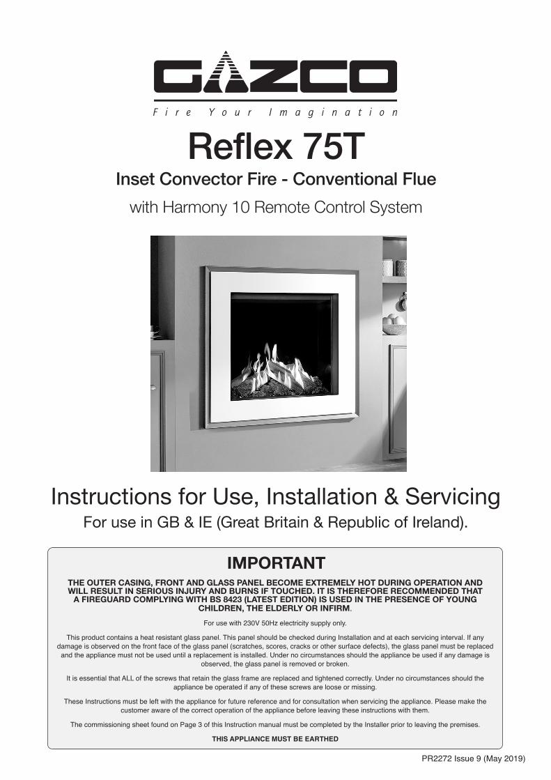
Instructions for Use, Installation & ServicingFor use in GB & IE (Great Britain & Republic of Ireland).
Reflex 75TInset Convector Fire - Conventional Flue
with Harmony 10 Remote Control System
THE OUTER CASING, FRONT AND GLASS PANEL BECOME EXTREMELY HOT DURING OPERATION AND WILL RESULT IN SERIOUS INJURY AND BURNS IF TOUCHED. IT IS THEREFORE RECOMMENDED THAT
A FIREGUARD COMPLYING WITH BS 8423 (LATEST EDITION) IS USED IN THE PRESENCE OF YOUNG CHILDREN, THE ELDERLY OR INFIRM.
For use with 230V 50Hz electricity supply only.
This product contains a heat resistant glass panel. This panel should be checked during Installation and at each servicing interval. If any damage is observed on the front face of the glass panel (scratches, scores, cracks or other surface defects), the glass panel must be replaced and the appliance must not be used until a replacement is installed. Under no circumstances should the appliance be used if any damage is
observed, the glass panel is removed or broken.
It is essential that ALL of the screws that retain the glass frame are replaced and tightened correctly. Under no circumstances should the appliance be operated if any of these screws are loose or missing.
These Instructions must be left with the appliance for future reference and for consultation when servicing the appliance. Please make the
customer aware of the correct operation of the appliance before leaving these instructions with them.
The commissioning sheet found on Page 3 of this Instruction manual must be completed by the Installer prior to leaving the premises.
THIS APPLIANCE MUST BE EARTHED
IMPORTANT
2
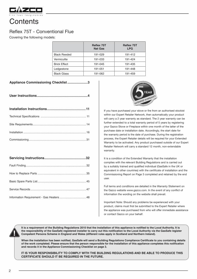
Reflex 75TNat Gas
Reflex 75TLPG
Black Reeded 191-029 191-412Vermiculite 191-033 191-424Brick Effect 191-045 191-435Ledgestone 191-051 191-448Black Glass 191-062 191-459
Appliance Commissioning Checklist ......................3
User Instructions .......................................................4
Installation Instructions ..........................................11
Technical Specifications .......................................................... 11
Site Requirements .................................................................... 14
Installation ................................................................................16
Commissioning .........................................................................31
Servicing Instructions .............................................32
Fault Finding .............................................................................32
How to Replace Parts ..............................................................35
Basic Spare Parts List ..............................................................45
Service Records .......................................................................47
Information Requirement - Gas Heaters ..................................48
Reflex 75T - Conventional Flue
Contents
Covering the following models:
It is a requirement of the Building Regulations 2010 that the installation of this appliance is notified to the Local Authority. It is the responsibility of the GasSafe registered installer to carry out this notification to the Local Authority via the GasSafe register Competent Persons Scheme in England and Wales (different rules apply in Scotland and Northern Ireland).
When the installation has been notified, GasSafe will send a Building Regulations Compliance Certificate to you containing details of the work completed. Please ensure that the person responsible for the installation of this appliance completes this notification and records it in the Appliance Commissioning Checklist on page 3.
IT IS YOUR RESPONSIBILITY TO COMPLY WITH THE BUILDING REGULATIONS AND BE ABLE TO PRODUCE THIS CERTIFICATE SHOULD IT BE REQUIRED IN THE FUTURE.
If you have purchased your stove or fire from an authorised stockist within our Expert Retailer Network, then automatically your product will carry a 2 year warranty as standard. The 2 year warranty can be further extended to a total warranty period of 5 years by registering your Gazco Stove or Fireplace within one month of the latter of the purchase date or installation date. Accordingly, the start date for the warranty period is the date of purchase. During the registration process, the Expert Retailer details will be required for your Extended Warranty to be activated. Any product purchased outside of our Expert Retailer Network will carry a standard 12 month, non-extendable warranty.
It is a condition of the Extended Warranty that the installation complies with the relevant Building Regulations and is carried out by a suitably trained and qualified individual (GasSafe in the UK or equivalent in other countries) with the certificate of installation and the Commissioning Report on Page 3 completed and retained by the end user.
Full terms and conditions are detailed in the Warranty Statement on the Gazco website www.gazco.com. In the event of any conflict of information the wording on the website shall prevail.
Important Note: Should any problems be experienced with your product, claims must first be submitted to the Expert Retailer where the appliance was purchased from who will offer immediate assistance or contact Gazco on your behalf.
3
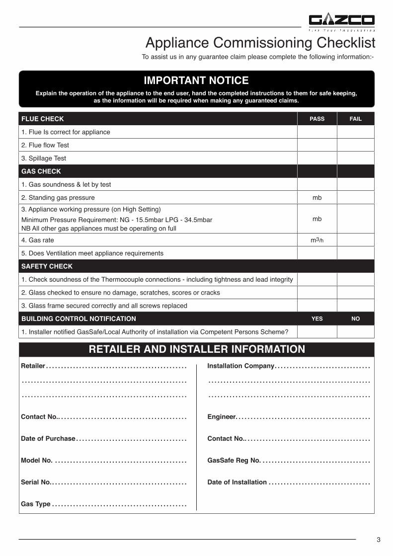
To assist us in any guarantee claim please complete the following information:-Appliance Commissioning Checklist
IMPORTANT NOTICEExplain the operation of the appliance to the end user, hand the completed instructions to them for safe keeping,
as the information will be required when making any guaranteed claims.
Retailer . . . . . . . . . . . . . . . . . . . . . . . . . . . . . . . . . . . . . . . . . . . . . . .
. . . . . . . . . . . . . . . . . . . . . . . . . . . . . . . . . . . . . . . . . . . . . . . . . . . . . . .
. . . . . . . . . . . . . . . . . . . . . . . . . . . . . . . . . . . . . . . . . . . . . . . . . . . . . . .
Contact No. . . . . . . . . . . . . . . . . . . . . . . . . . . . . . . . . . . . . . . . . . . .
Date of Purchase . . . . . . . . . . . . . . . . . . . . . . . . . . . . . . . . . . . . .
Model No. . . . . . . . . . . . . . . . . . . . . . . . . . . . . . . . . . . . . . . . . . . . .
Serial No. . . . . . . . . . . . . . . . . . . . . . . . . . . . . . . . . . . . . . . . . . . . . .
Gas Type . . . . . . . . . . . . . . . . . . . . . . . . . . . . . . . . . . . . . . . . . . . . .
Installation Company . . . . . . . . . . . . . . . . . . . . . . . . . . . . . . . .
. . . . . . . . . . . . . . . . . . . . . . . . . . . . . . . . . . . . . . . . . . . . . . . . . . . . . .
. . . . . . . . . . . . . . . . . . . . . . . . . . . . . . . . . . . . . . . . . . . . . . . . . . . . . .
Engineer. . . . . . . . . . . . . . . . . . . . . . . . . . . . . . . . . . . . . . . . . . . . .
Contact No. . . . . . . . . . . . . . . . . . . . . . . . . . . . . . . . . . . . . . . . . . .
GasSafe Reg No. . . . . . . . . . . . . . . . . . . . . . . . . . . . . . . . . . . . .
Date of Installation . . . . . . . . . . . . . . . . . . . . . . . . . . . . . . . . . .
RETAILER AND INSTALLER INFORMATION
FLUE CHECK PASS FAIL
1. Flue Is correct for appliance
2. Flue flow Test
3. Spillage Test
GAS CHECK
1. Gas soundness & let by test
2. Standing gas pressure mb3. Appliance working pressure (on High Setting)Minimum Pressure Requirement: NG - 15.5mbar LPG - 34.5mbarNB All other gas appliances must be operating on full
mb
4. Gas rate m3/h
5. Does Ventilation meet appliance requirements
SAFETY CHECK
1. Check soundness of the Thermocouple connections - including tightness and lead integrity
2. Glass checked to ensure no damage, scratches, scores or cracks
3. Glass frame secured correctly and all screws replaced
BUILDING CONTROL NOTIFICATION YES NO
1. Installer notified GasSafe/Local Authority of installation via Competent Persons Scheme?
4
Welcome
Congratulations on purchasing your Reflex fire, if installed correctly Gazco hope it will give you many years of warmth and pleasure for which it was designed.
The purpose of this manual is to familiarise you with your appliance, and give guidelines for its installation, operation and maintenance. If, after reading, you need further information, please do not hesitate to contact your Gazco retailer.
WARNING
In the event of a gas escape or if you can smell gas, please take the following steps:
• Immediately turn off the gas supply at the meter/emergency control valve
• Extinguish all sources of ignition
• Do not smoke
• Do not operate any electrical light or power switches (On or Off)
• Ventilate the building(s) by opening doors and windows
• Ensure access to the premises can be made
Please report the incident immediately to the National Gas Emergency Service Call Centre on 0800 111 999 (England, Scotland and Wales), 0800 002 001 (N. Ireland) or in the case of LPG, the gas supplier whose details can be found on the bulk storage vessel or cylinder.
The gas supply must not be used until remedial action has been taken to correct the defect and the installation has been recommissioned by a competent person.
1. General1.1 Installation and servicing must only be carried out by a
competent person whose name appears on the GasSafe register. To ensure the engineer is registered with GasSafe they should possess an ID Card carrying the following logo:
1.2 In all correspondence, please quote the appliance type and serial number, which can be found on the data badge located on a plate under the Main Burner.
1.3 Do not place curtains above the appliance: You must have 300mm clearance between the appliance
and any curtains at either side.
1.4 No furnishings or other objects should be placed within 1 metre of the front of the appliance.
1.5 If a shelf is fitted, a distance of 400mm above the appliance is required.
1.6 If any cracks appear in the glass panel do not use the appliance until the panel has been replaced.
1.7 When the appliance has been installed the position of the plug must be accessible.
1.8 Where the electricity supply cable has to pass through a fire place, stone surround etc. ensure suitable rubber bushes are fitted at possible wear points.
1.9 If the electricity supply cable is damaged do not use the appliance until it has been replaced. For safety reasons the replacement has to be carried out by Gazco, a Gazco service agent or a similarly competent electrician.
1.10 Repairs of electrical appliances must only be performed by an electrical engineer. Should the appliance fail to operate,
or in case of any damage, please contact the retailer from whom the appliance was purchased.
1.11 This product is guaranteed for 5 years from the date of installation, as set out in the terms and conditions of sale between Gazco and your local Gazco retailer. Please consult with your local Gazco retailer if you have any questions. In all correspondence always quote the Model Number and Serial Number.
1.12 This appliance is not intended to be used by persons under the age of 12, persons with reduced physical, sensory or mental capabilities or persons with lack of experience and knowledge in the safe operation of the appliance.
The appliance may be operated by persons above the age of 12 provided they have been instructed in the safe use of the appliance and that they understand the hazards involved. Persons above the age of 12 may also operate the appliance under the supervision of a responsible adult.
Cleaning and Maintenance of the appliance must be undertaken by a suitably qualified adult.
CHILDREN MUST BE SUPERVISED TO ENSURE THEY DO NOT PLAY WITH THE APPLIANCE.
User Instructions
5
2. Operating the Appliance
The appliance is operated by thermostatic and programmable remote control.
1
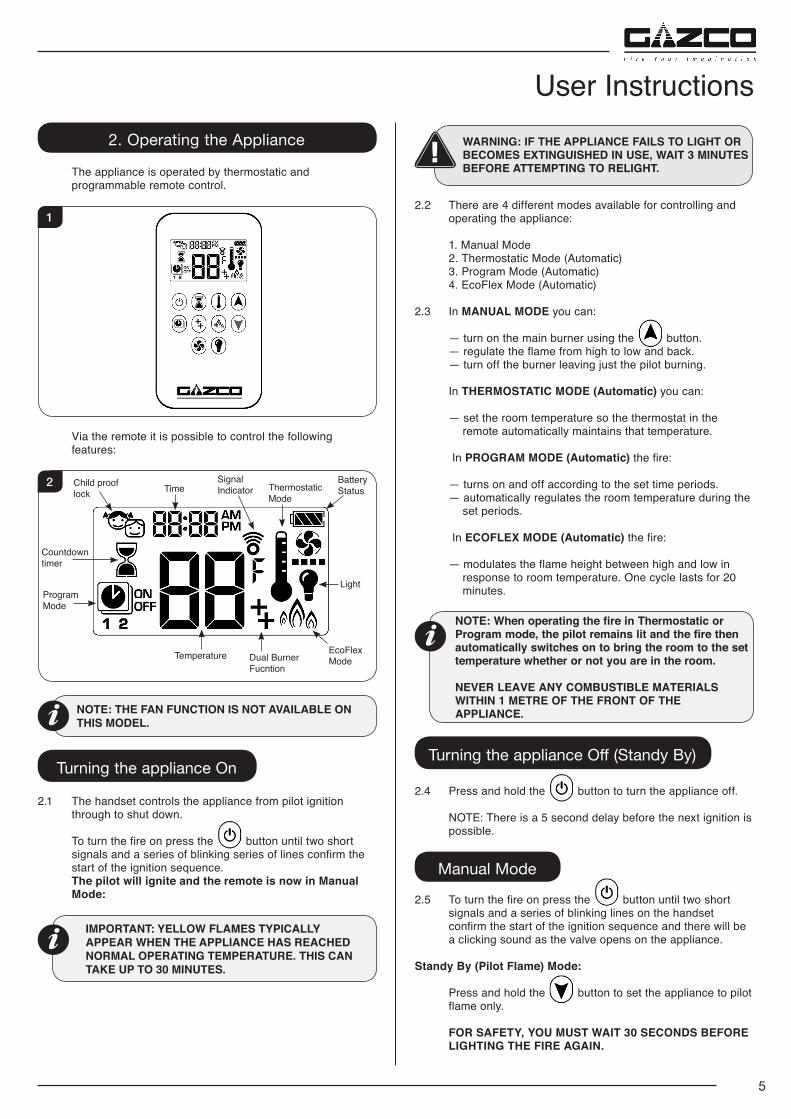
Via the remote it is possible to control the following features:
2 Child proof lock Time
Light
EcoFlex Mode
Signal Indicator Thermostatic
Mode
Dual Burner Fucntion
Temperature
Program Mode
Countdown timer
Battery Status
NOTE: THE FAN FUNCTION IS NOT AVAILABLE ON THIS MODEL.
Turning the appliance On
2.1 The handset controls the appliance from pilot ignition through to shut down.
To turn the fire on press the button until two short signals and a series of blinking series of lines confirm the start of the ignition sequence.
The pilot will ignite and the remote is now in Manual Mode:
IMPORTANT: YELLOW FLAMES TYPICALLY APPEAR WHEN THE APPLIANCE HAS REACHED NORMAL OPERATING TEMPERATURE. THIS CAN TAKE UP TO 30 MINUTES.
WARNING: IF THE APPLIANCE FAILS TO LIGHT OR BECOMES EXTINGUISHED IN USE, WAIT 3 MINUTES BEFORE ATTEMPTING TO RELIGHT.
2.2 There are 4 different modes available for controlling and operating the appliance:
1. Manual Mode 2. Thermostatic Mode (Automatic) 3. Program Mode (Automatic) 4. EcoFlex Mode (Automatic)
2.3 In MANUAL MODE you can:
— turn on the main burner using the button. — regulate the flame from high to low and back. — turn off the burner leaving just the pilot burning.
In THERMOSTATIC MODE (Automatic) you can:
— set the room temperature so the thermostat in the remote automatically maintains that temperature.
In PROGRAM MODE (Automatic) the fire:
— turns on and off according to the set time periods. — automatically regulates the room temperature during the
set periods.
In ECOFLEX MODE (Automatic) the fire:
— modulates the flame height between high and low in response to room temperature. One cycle lasts for 20 minutes.
NOTE: When operating the fire in Thermostatic or Program mode, the pilot remains lit and the fire then automatically switches on to bring the room to the set temperature whether or not you are in the room.
NEVER LEAVE ANY COMBUSTIBLE MATERIALS WITHIN 1 METRE OF THE FRONT OF THE APPLIANCE.
Turning the appliance Off (Standy By)
2.4 Press and hold the button to turn the appliance off.
NOTE: There is a 5 second delay before the next ignition is possible.
Manual Mode
2.5 To turn the fire on press the button until two short signals and a series of blinking lines on the handset confirm the start of the ignition sequence and there will be a clicking sound as the valve opens on the appliance.
Standy By (Pilot Flame) Mode:
Press and hold the button to set the appliance to pilot flame only.
FOR SAFETY, YOU MUST WAIT 30 SECONDS BEFORE LIGHTING THE FIRE AGAIN.
User Instructions
6
Increasing the Flame Height:
To increase flame height press and hold button.
Decreasing the Flame Height:
To decrease flame height or to set the appliance to pilot flame press and hold the button.
NOTE: While pressing a button a symbol indicating transmission appears on the display. The receiver confirms transmission with a sound signal.
Thermostatic Mode (Automatic)
2.6 To select the Thermostatic mode press the button. The preset temperature will show briefly then the current
room temperature will be displayed.
Setting the temperature:
Press and hold the button until the temperature display flashes.
Adjust the temperature by pressing the or button.
Press the button to confirm the temperature.
NOTE: If you set a temperature that is beneath the current room temperature, the fire automatically switches to PILOT (Stand by).
Exiting Thermostatic Mode:
Press the button to exit Thermostatic mode.
Press the or button to enter Manual Mode.
Press the button to enter Program Mode.
Press the button to enter EcoFlex Mode.
Program Mode (Automatic)
2.7 To select the Program mode press the button. The set temperature for the On time is the one set in
Thermostatic Mode. Changing the thermostat temperature changes the temperature in Program mode.
Default Settings
The On time (Thermostatic) Temperature is 21°C (70°F). The Off time Temperature is '--' (Pilot flame only).
Temperature Settings
Press the button and hold until the display flashes ON and set the temperature (See Thermostatic Mode) is displayed.
Press the button or wait until OFF is displayed and the temperature flashes.
Adjust the temperature by pressing the or button.
Press the button to confirm the temperature or wait.
NOTE: The On (Thermostatic) and Off set temperature is the same for each day.
Day Setting:
Press the button again, ALL Flashes.
Press or button to choose between ALL, SA,SU, 1, 2, 3, 4, 5, 6, 7.
Press the button to confirm.
ALL Selected
ON TIME SETTING (PROGRAM 1):
, 1 ON displayed, ALL is displayed shortly and hour flashes.
Select the hour by pressing the or button.
Press the button to confirm. , 1 ON displayed, ALL is displayed shortly and minutes flashes.
Select the minutes by pressing the or button.
Press the button to confirm.
OFF TIME SETTING (PROGRAM 1):
, 1 OFF displayed, ALL is displayed shortly and hour flashes.
Select the hour by pressing the or button.
Press the button to confirm. , 1 OFF displayed, ALL is displayed shortly and minutes flashes.
Select the minutes by pressing the or button.
Press the button to confirm.
NOTE: either continue to PROGRAM 2 and set on and off times or stop programming at this point and PROGRAM 2 remains deactivated.
PROGRAM 1 and PROGRAM 2 use the same On (Thermostatic) and Off temperatures for ALL, SA:SU and Daily Timer (1, 2, 3, 4, 5, 6, 7). Once a new On (Thermostatic) and/or Off temperature has been set, that temperature becomes the new default setting.
If ALL, SA:SU or Daily Timer are programmed for PROGRAM 1 and PROGRAM 2 On and Off times these become the new default times. The batteries must be removed to clear PROGRAM 1 and 2 On and Off times and temperatures.
User Instructions
7
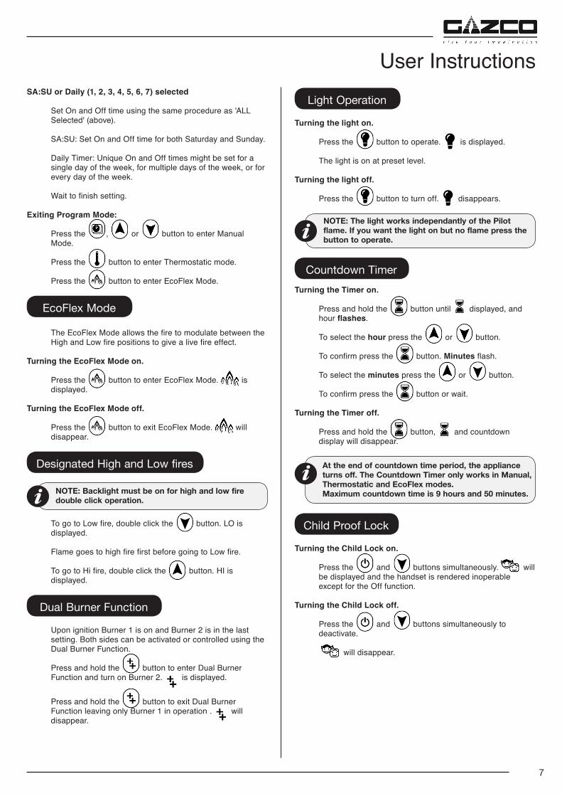
SA:SU or Daily (1, 2, 3, 4, 5, 6, 7) selected
Set On and Off time using the same procedure as 'ALL Selected' (above).
SA:SU: Set On and Off time for both Saturday and Sunday.
Daily Timer: Unique On and Off times might be set for a single day of the week, for multiple days of the week, or for every day of the week.
Wait to finish setting.
Exiting Program Mode:
Press the , or button to enter Manual Mode.
Press the button to enter Thermostatic mode.
Press the button to enter EcoFlex Mode.
EcoFlex Mode
The EcoFlex Mode allows the fire to modulate between the High and Low fire positions to give a live fire effect.
Turning the EcoFlex Mode on.
Press the button to enter EcoFlex Mode. is displayed.
Turning the EcoFlex Mode off.
Press the button to exit EcoFlex Mode. will disappear.
Designated High and Low fires
NOTE: Backlight must be on for high and low fire double click operation.
To go to Low fire, double click the button. LO is displayed.
Flame goes to high fire first before going to Low fire.
To go to Hi fire, double click the button. HI is displayed.
Dual Burner Function
Upon ignition Burner 1 is on and Burner 2 is in the last setting. Both sides can be activated or controlled using the Dual Burner Function.
Press and hold the button to enter Dual Burner Function and turn on Burner 2. is displayed.
Press and hold the button to exit Dual Burner Function leaving only Burner 1 in operation . will disappear.
Light Operation
Turning the light on.
Press the button to operate. is displayed.
The light is on at preset level.
Turning the light off.
Press the button to turn off. disappears.
NOTE: The light works independantly of the Pilot flame. If you want the light on but no flame press the button to operate.
Countdown TimerTurning the Timer on.
Press and hold the button until displayed, and hour flashes.
To select the hour press the or button.
To confirm press the button. Minutes flash.
To select the minutes press the or button.
To confirm press the button or wait.
Turning the Timer off.
Press and hold the button, and countdown display will disappear.
At the end of countdown time period, the appliance turns off. The Countdown Timer only works in Manual, Thermostatic and EcoFlex modes.Maximum countdown time is 9 hours and 50 minutes.
Child Proof Lock
Turning the Child Lock on.
Press the and buttons simultaneously. will be displayed and the handset is rendered inoperable except for the Off function.
Turning the Child Lock off.
Press the and buttons simultaneously to deactivate.
will disappear.
User Instructions
8
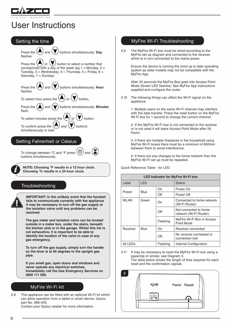
User InstructionsSetting the time
Press the and buttons simultaneously. Day flashes.
Press the or button to select a number that corresponds with a day of the week (eg 1 = Monday, 2 = Tuesday, 3 = Wednesday, 4 = Thursday, 5 = Friday, 6 = Saturday, 7 = Sunday).
Press the and buttons simultaneously. Hour flashes.
To select hour press the or button.
Press the and buttons simultaneously. Minutes flash.
To select minutes press the or button.
To confirm press the and buttons simultaneously or wait.
Setting Fahrenheit or Celsius
To change between °C and °F press and buttons simultaneously.
NOTE: Choosing °F results in a 12 hour clock. Choosing °C results in a 24 hour clock.
Troubleshooting
IMPORTANT: In the unlikely event that the handset fails to communicate correctly with the appliance it may be necessary to turn off the gas supply at the isolation valve until any problems can be resolved.
The gas meter and isolation valve can be located outside in a meter box, under the stairs, beneath the kitchen sink or in the garage. Whilst this list is not exhaustive, it is important to be able to identify the location of the valve in case of any gas emergency.
To turn off the gas supply, simply turn the handle so the lever is at 90 degrees to the upright gas pipe.
If you smell gas, open doors and windows and never operate any electrical switches. Immediately call the Gas Emergency Services on 0800 111 999.
MyFire Wi-Fi kit2.8 This appliance can be fitted with an optional Wi-Fi kit which
can allow operation from a tablet or smart device, Gazco part No. 999-055.
Contact your Gazco retailer for more information.
MyFire Wi-Fi Troubleshooting
2.9 The MyFire Wi-Fi box must be wired according to the MyFire set up diagram and connected to the receiver, which is in turn connected to the mains power.
Ensure the device is running the most up to date operating system as older models may not be compatible with the MyFire App.
After 30 seconds the MyFire Box goes into Access Point Mode (Green LED flashes). See MyFire App instructions supplied and configure the router.
2.10 The following things can affect the Wi-Fi signal on the appliance:
1. Multiple users on the same Wi-Fi channel may interfere
with the data transfer. Press the reset button on the MyFire Wi-Fi box for 1 second to change the current channel.
2. If the MyFire Wi-Fi box is not connected to the receiver or is not used it will leave Access Point Mode after 24 hours.
3. If there are multiple fireplaces in the household using MyFire Wi-Fi boxes there must be a minimum of 600mm between them to avoid interference.
4. If there are any changes to the home network then the MyFire Wi-Fi set up must be repeated.
Quick Reference Table - for LED.
LED Indicator for MyFire Wi-Fi box
Label LED Status
Power BlueOn Power OnOff Power Off
WLAN Green On Connected to home network (Wi-Fi Router)
Off Not connected to home network (Wi-Fi Router)
Flashing MyFire Wi-Fi Box in Access Point Mode
Receiver Blue On Receiver connected
Off No receiver connected or connection lost
All LEDs Flashing Internal Configuration
2.11 It may be necessary to reset the MyFire Wi-Fi box using a paperclip or similar, see Diagram 3.
The table below shows the length of time required for each reset and the confirmation signals.
3
9
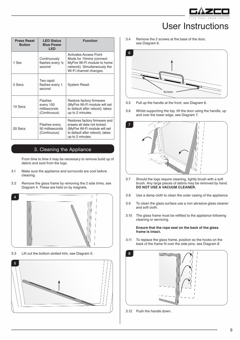
User InstructionsPress Reset
ButtonLED StatusBlue Power
LED
Function
1 SecContinuously flashes every ½ second
Activates Access Point Mode for 10mins (connect MyFire Wi-Fi module to home network). Simultaneously the Wi-Fi channel changes.
5 SecsTwo rapid flashes every 1 second
System Reset.
10 SecsFlashes every 100 milliseconds (Continuous)
Restore factory firmware (MyFire Wi-Fi module will set to default after reboot); takes up to 2 minutes.
20 SecsFlashes every 50 milliseconds (Continuous)
Restores factory firmware and erases all data not locked. (MyFire Wi-Fi module will set to default after reboot); takes up to 2 minutes.
3. Cleaning the Appliance
From time to time it may be necessary to remove build up of debris and soot from the logs.
3.1 Make sure the appliance and surrounds are cool before cleaning.
3.2 Remove the glass frame by removing the 2 side trims, see Diagram 4. These are held on by magnets.
4
3.3 Lift out the bottom slotted trim, see Diagram 5.
5
3.4 Remove the 2 screws at the base of the door, see Diagram 6.
6
Screws
3.5 Pull up the handle at the front, see Diagram 6.
3.6 Whilst supporting the top, lift the door using the handle, up and over the lower edge, see Diagram 7.
7
3.7 Should the logs require cleaning, lightly brush with a soft brush. Any large pieces of debris may be removed by hand.
DO NOT USE A VACUUM CLEANER.
3.8 Use a damp cloth to clean the outer casing of the appliance.
3.9 To clean the glass surface use a non abrasive glass cleaner and soft cloth.
3.10 The glass frame must be refitted to the appliance following cleaning or servicing.
Ensure that the rope seal on the back of the glass frame is intact.
3.11 To replace the glass frame, position so the hooks on the back of the frame fit over the side pins, see Diagram 8.
8
3.12 Push the handle down.
10
3.13 Replace the screws. As the screws are tightened the glass frame is pulled down against the hooks and forms a seal.
Replace ALL of the securing screws ensuring that a screw is present in all fixing slots.
UNDER NO CIRCUMSTANCES SHOULD THE APPLIANCE BE USED IF ANY OF THE GLASS FRAME RETAINING SCREWS ARE LOOSE OR MISSING.
3.14 Replace the lower trim.
3.15 Replace the 2 magnetic side trims.
NEVER OPERATE THE APPLIANCE WHEN THE GLASS PANEL IS REMOVED OR BROKEN.
3.16 Replace the decorative front by referring to the separate instructions supplied with the front.
4. Oxygen Depletion Sensor The appliance is fitted with an oxygen sensitive pilot system
that will act to cut off the gas supply to the appliance should the oxygen in the room fall below its normal level. If the appliance is turned off by this device it usually indicates that there is a problem with the flue system, this should be inspected by a qualified engineer.
DO NOT ATTEMPT TO USE THE APPLIANCE UNTIL AN ENGINEER SAYS IT IS SAFE TO DO SO.
THIS DEVICE IS NOT A SUBSTITUTE FOR AN INDEPENDENTLY MOUNTED CARBON MONOXIDE DETECTOR.
5. Flame Failure Device
5.1 This is a safety feature incorporated on this appliance which automatically switches off the gas supply if the pilot goes out and fails to heat the thermocouple.
IF THIS OCCURS DO NOT ATTEMPT TO RELIGHT THE APPLIANCE FOR 3 MINUTES.
6. Running In
6.1 During initial use of a new Gazco appliance a strong odour will be encountered as various surface coatings become hot for the first time. Although these odours are harmless it is recommended that the appliance is operated on maximum for 4 to 8 hours in order to fully burn off these coatings. After this period the odours should then disappear.
If the odours persists, please contact your installer for advice.
6.2 During the first few hours of burning there may be discolouration of the flames. This will also disappear after a short period of use.
User Instructions7. Servicing
7.1 The appliance must be serviced every 12 months by a qualified Gas Engineer. In all correspondence always quote the Model number and the Serial number which may be found on the Commissioning Checklist (Page 3).
8. Ventilation
8.1 Any purpose provided ventilation should be checked periodically to ensure that it is free from obstruction.
9. Installation Details
9.1 Your installer should have completed the commissioning sheet at the front of this book. This records the essential installation details of the appliance. In all correspondence always quote the Model number and Serial number.
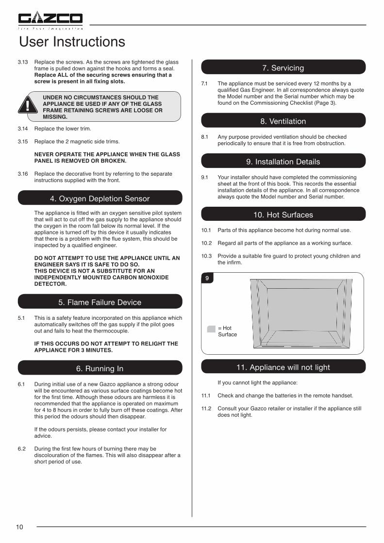
10. Hot Surfaces
10.1 Parts of this appliance become hot during normal use.
10.2 Regard all parts of the appliance as a working surface.
10.3 Provide a suitable fire guard to protect young children and the infirm.
= Hot Surface
9
11. Appliance will not light
If you cannot light the appliance:
11.1 Check and change the batteries in the remote handset.
11.2 Consult your Gazco retailer or installer if the appliance still does not light.
11
Installation Instructions
Model Gas CAT. Gas Type Working
PressureGas Rate
m3/h
Input kW (Gross) Country
High Low
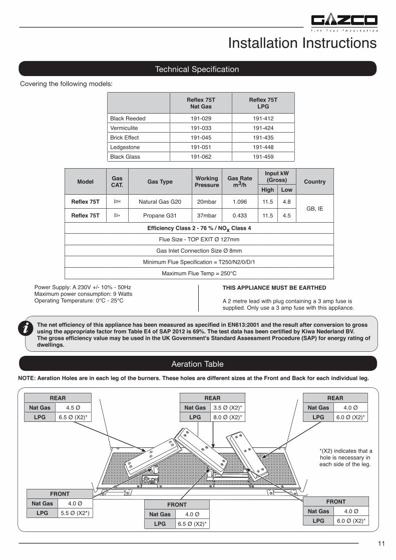
Reflex 75T I2H Natural Gas G20 20mbar 1.096 11.5 4.8GB, IE
Reflex 75T I3+ Propane G31 37mbar 0.433 11.5 4.5
Efficiency Class 2 - 76 % / NOx Class 4
Flue Size - TOP EXIT Ø 127mm
Gas Inlet Connection Size Ø 8mm
Minimum Flue Specification = T250/N2/0/D/1
Maximum Flue Temp = 250°C
Technical SpecificationCovering the following models:
The net efficiency of this appliance has been measured as specified in EN613:2001 and the result after conversion to gross using the appropriate factor from Table E4 of SAP 2012 is 69%. The test data has been certified by Kiwa Nederland BV. The gross efficiency value may be used in the UK Government's Standard Assessment Procedure (SAP) for energy rating of dwellings.
Reflex 75TNat Gas
Reflex 75TLPG
Black Reeded 191-029 191-412Vermiculite 191-033 191-424Brick Effect 191-045 191-435Ledgestone 191-051 191-448Black Glass 191-062 191-459
Power Supply: A 230V +/- 10% - 50Hz Maximum power consumption: 9 Watts Operating Temperature: 0°C - 25°C
THIS APPLIANCE MUST BE EARTHED
A 2 metre lead with plug containing a 3 amp fuse is supplied. Only use a 3 amp fuse with this appliance.
Aeration TableNOTE: Aeration Holes are in each leg of the burners. These holes are different sizes at the Front and Back for each individual leg.
FRONTNat Gas 4.0 Ø
LPG 5.5 Ø (X2*)
REARNat Gas 4.5 Ø
LPG 6.5 Ø (X2)*
FRONTNat Gas 4.0 Ø
LPG 6.5 Ø (X2)*
REARNat Gas 3.5 Ø (X2)*
LPG 8.0 Ø (X2)*
FRONTNat Gas 4.0 Ø
LPG 6.0 Ø (X2)*
REARNat Gas 4.0 Ø
LPG 6.0 Ø (X2)*
*(X2) indicates that a hole is necessary in each side of the leg.
12
Installation Instructions
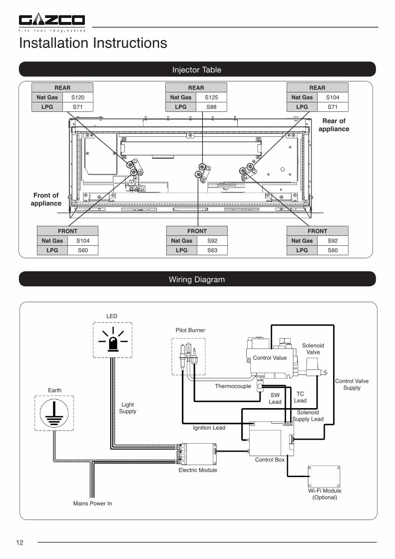
Wiring Diagram
Injector Table
Front of appliance
Rear of appliance
REARNat Gas S120
LPG S71
FRONTNat Gas S104
LPG S60
FRONTNat Gas S92
LPG S63
REARNat Gas S125
LPG S88
REARNat Gas S104
LPG S71
FRONTNat Gas S92
LPG S60
Mains Power In
Earth
LED
Pilot Burner
Control Value
Thermocouple
Solenoid Valve
SolenoidSupply Lead
Control Valve Supply
Control Box
Electric Module
Light Supply
Ignition Lead
TC Lead
SW Lead
Wi-Fi Module(Optional)
13
Technical Specification
PACKING CHECKLIST
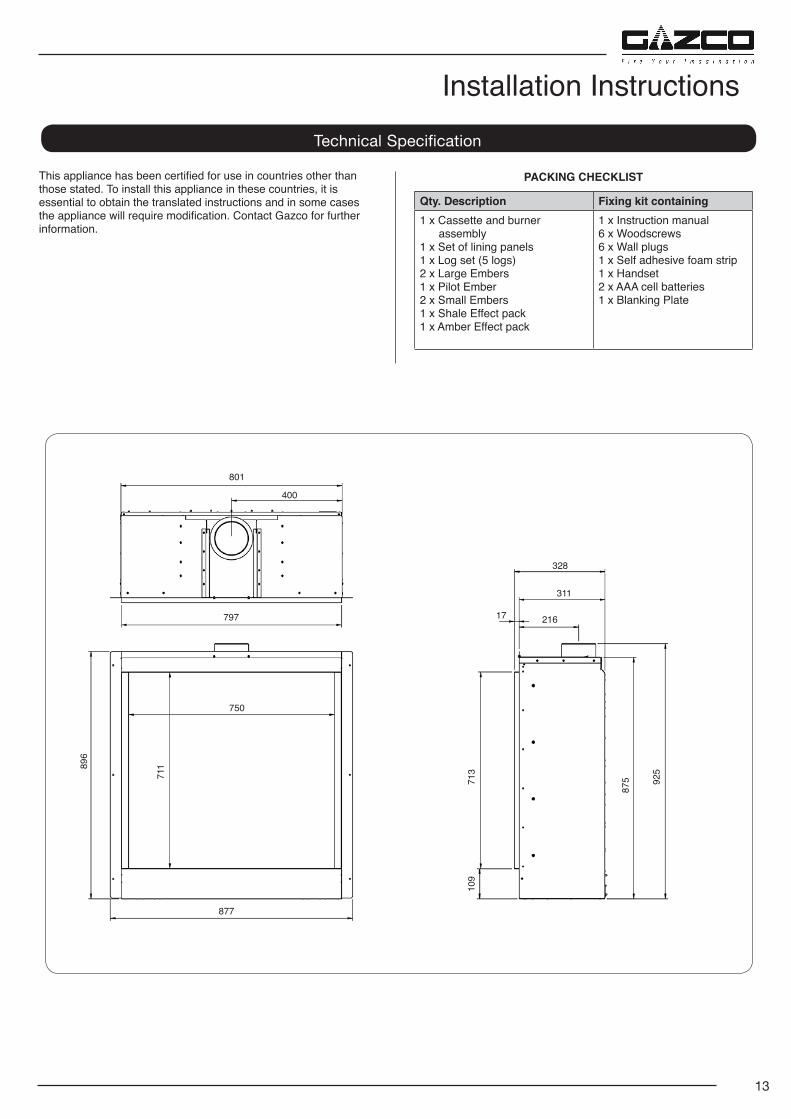
Qty. Description Fixing kit containing1 x Cassette and burner
assembly1 x Set of lining panels1 x Log set (5 logs)2 x Large Embers1 x Pilot Ember2 x Small Embers1 x Shale Effect pack1 x Amber Effect pack
1 x Instruction manual6 x Woodscrews6 x Wall plugs1 x Self adhesive foam strip1 x Handset2 x AAA cell batteries1 x Blanking Plate
This appliance has been certified for use in countries other than those stated. To install this appliance in these countries, it is essential to obtain the translated instructions and in some cases the appliance will require modification. Contact Gazco for further information.
Installation Instructions
877
750
875 92
5
801
400
797
328
311
21617
896
711
109
713
14
Installation Instructions
1. Flue & Chimney Requirements
WHEN INSTALLING A FLUE SYSTEM PLEASE REFER TO THE MANUFACTURER’S INSTRUCTIONS.
The European chimney standards now describe chimneys and flues by their temperature, pressure and resistance to corrosion, condensation and fire. To identify the correct flue system, the minimum flue specification is shown in the Technical Specification. Existing chimneys are not covered by this system.
The flue must be installed in accordance with all local and national regulations and the current rules in force:
1.1 The chimney or flue system must comply with the rules in force, and must be 127mm (5") in diameter.
1.2 A flexible liner must be continuous from the appliance spigot to the roof terminal.
1.3 The minimum effective height of the flue must be 3m (10').
1.4 The flue must be free from any obstruction.
1.5 Any damper plates must be removed or secured in the fully open position and no restrictor plates fitted.
1.6 The chimney should be swept immediately before installing the appliance, but it need not be swept if you can see the chimney is clean and free from obstruction throughout.
2. Flue Options
There are three main suitable Conventional Flues:
— Top Exit - Builder’s Opening Lined 127mm (5”)
— Rear Exit - Builder’s Opening Unlined 178m (7”) minimum
— Stud work is Top Exit only - Twin Wall Rigid 127mm (5”)
3. Gas Supply
This appliance is intended for use on a gas installation with a governed meter.
3.1 Make sure local distribution conditions (identification of the type of gas and pressure) and the adjustment of the appliance are compatible before installation.
3.2 Ensure the gas supply delivers the required amount of gas and is in accordance with the rules in force.
3.3 Soft copper tubing can be used on the installation and soft soldered joints outside the appliance.
3.4 A factory fitted isolation device is part of the inlet connection; no further isolation device is required.
3.5 All supply gas pipes must be purged of any debris that may have entered prior to connection to the appliance.
3.6 The gas supply enters through the silicone panel located on the LEFT-HAND side on the rear of the outer box. Slit with a sharp knife prior to passing the supply pipe through.
3.7 The gas supply must be installed in a way that does not restrict the removal of the appliance for servicing and inspection.
4. Ventilation
IMPORTANT: Ensure any national ventilation requirements are taken into account during installation of the appliance.
UK ONLY: The appliance has a nominal input exceeding 7.0kW and
must have permanent ventilation with a minimum open area of 22.4cm2.
If however, spillage is detected when commissioning the appliance, there may be insufficient natural ventilation and additional ventilation may be required.
FOR THE REPUBLIC OF IRELAND REFER TO THE RULES IN FORCE FOR VENTILATION REQUIREMENTS.
5. Appliance Location
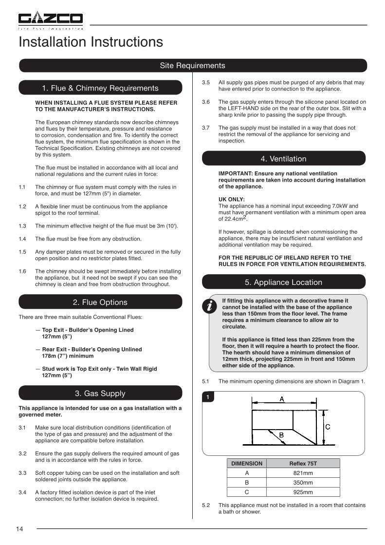
If fitting this appliance with a decorative frame it cannot be installed with the base of the appliance less than 150mm from the floor level. The frame requires a minimum clearance to allow air to circulate.
If this appliance is fitted less than 225mm from the floor, then it will require a hearth to protect the floor. The hearth should have a minimum dimension of 12mm thick, projecting 225mm in front and 150mm either side of the appliance.
5.1 The minimum opening dimensions are shown in Diagram 1.
1
DIMENSION Reflex 75TA 821mmB 350mmC 925mm
5.2 This appliance must not be installed in a room that contains a bath or shower.
Site Requirements
15
Site Requirements
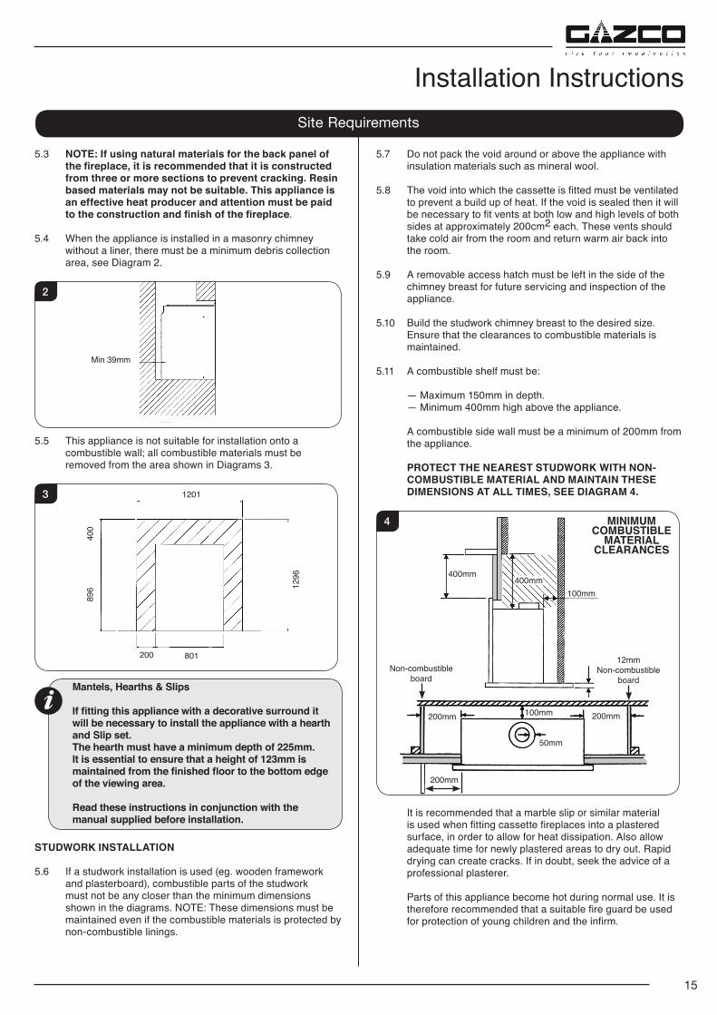
5.3 NOTE: If using natural materials for the back panel of the fireplace, it is recommended that it is constructed from three or more sections to prevent cracking. Resin based materials may not be suitable. This appliance is an effective heat producer and attention must be paid to the construction and finish of the fireplace.
5.4 When the appliance is installed in a masonry chimney without a liner, there must be a minimum debris collection area, see Diagram 2.
2
Min 39mm
5.5 This appliance is not suitable for installation onto a combustible wall; all combustible materials must be removed from the area shown in Diagrams 3.
3 1201
801200
896
400
1296
Mantels, Hearths & Slips
If fitting this appliance with a decorative surround it will be necessary to install the appliance with a hearth and Slip set. The hearth must have a minimum depth of 225mm. It is essential to ensure that a height of 123mm is maintained from the finished floor to the bottom edge of the viewing area.
Read these instructions in conjunction with the manual supplied before installation.
STUDWORK INSTALLATION
5.6 If a studwork installation is used (eg. wooden framework and plasterboard), combustible parts of the studwork must not be any closer than the minimum dimensions shown in the diagrams. NOTE: These dimensions must be maintained even if the combustible materials is protected by non-combustible linings.
5.7 Do not pack the void around or above the appliance with insulation materials such as mineral wool.
5.8 The void into which the cassette is fitted must be ventilated to prevent a build up of heat. If the void is sealed then it will be necessary to fit vents at both low and high levels of both sides at approximately 200cm2 each. These vents should take cold air from the room and return warm air back into the room.
5.9 A removable access hatch must be left in the side of the chimney breast for future servicing and inspection of the appliance.
5.10 Build the studwork chimney breast to the desired size. Ensure that the clearances to combustible materials is maintained.
5.11 A combustible shelf must be:
— Maximum 150mm in depth. — Minimum 400mm high above the appliance.
A combustible side wall must be a minimum of 200mm from the appliance.
PROTECT THE NEAREST STUDWORK WITH NON-COMBUSTIBLE MATERIAL AND MAINTAIN THESE DIMENSIONS AT ALL TIMES, SEE DIAGRAM 4.
MINIMUMCOMBUSTIBLE
MATERIAL CLEARANCES
4
400mm100mm
400mm
100mm200mm
200mm
200mm
50mm
12mm Non-combustible
boardNon-combustible
board
It is recommended that a marble slip or similar material is used when fitting cassette fireplaces into a plastered surface, in order to allow for heat dissipation. Also allow adequate time for newly plastered areas to dry out. Rapid drying can create cracks. If in doubt, seek the advice of a professional plasterer.
Parts of this appliance become hot during normal use. It is therefore recommended that a suitable fire guard be used for protection of young children and the infirm.
Installation Instructions
16
Installation Instructions1. Safety Precautions
1.1 For your own and other’s safety, you must install this
appliance according to local and national codes of practice. Failure to install the appliance correctly could lead to prosecution. Read these instructions before installing and using this appliance.
1.2 These instructions must be left intact with the user.
1.3 Do not attempt to burn rubbish on this appliance.
1.4 Keep all plastic bags away from young children.
1.5 Do not place any object on or near to the appliance and allow adequate clearance above the appliance.
IF THE APPLIANCE IS EXTINGUISHED OR GOES OUT IN USE, WAIT 3 MINUTES BEFORE ATTEMPTING TO RELIGHT THE APPLIANCE.
1.6 The appliance is fitted with an oxygen sensitive pilot that will act to cut off the gas supply to the appliance in the event of incorrect operation of the flue.
If the system acts to shut off the gas supply, this indicates that there is insufficient flue pull. Continued operation of this safety device means that there may be a serious problem with the flue system, and this should be inspected by a qualified gas engineer. Do not use the appliance until an engineer says it is safe to do so.
The oxygen sensitive pilot must not be tampered with. Use only genuine Gazco replacement parts when servicing the appliance - refer to Servicing section.
IMPORTANT: REFER TO DATA BADGE AND TECHNICAL SPECIFICATION AT THE FRONT OF THE MANUAL TO ENSURE THE APPLIANCE IS CORRECTLY ADJUSTED FOR THE GAS TYPE AND CATEGORY APPLICABLE IN THE COUNTRY OF USE.
FOR DETAILS OF CHANGING BETWEEN GAS TYPES REFER TO SERVICING, SECTION 15, REPLACING PARTS.
Unpacking
1.7 Remove the appliance from its packaging, and check that it is complete and undamaged.
Put the loose ceramic parts to one side so that they are not damaged during installation.
2. Installation of the Appliance
2.1 This appliance can be installed in four different ways:
1) Builder’s opening with an Edge finish. 2) Builder’s opening with a decorative front. 3) Studwork with an Edge finish. 4) Studwork with a decorative front.
Flue Attachment For additional information please refer to Site Requirements
section, page 14.
Options 1 and 2 above can be:
— Top exit with a liner - 5" (127mm). — Rear exit without a liner - 7" (178mm) minimum.
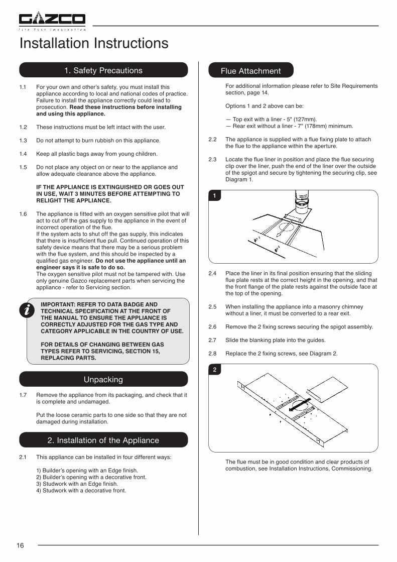
2.2 The appliance is supplied with a flue fixing plate to attach the flue to the appliance within the aperture.
2.3 Locate the flue liner in position and place the flue securing clip over the liner, push the end of the liner over the outside of the spigot and secure by tightening the securing clip, see Diagram 1.
1
2.4 Place the liner in its final position ensuring that the sliding flue plate rests at the correct height in the opening, and that the front flange of the plate rests against the outside face at the top of the opening.
2.5 When installing the appliance into a masonry chimney without a liner, it must be converted to a rear exit.
2.6 Remove the 2 fixing screws securing the spigot assembly.
2.7 Slide the blanking plate into the guides.
2.8 Replace the 2 fixing screws, see Diagram 2.
2
The flue must be in good condition and clear products of combustion, see Installation Instructions, Commissioning.
17
Installation Instructions2.9 If a flexible liner is to be used check the seal on the inner lip
of the spigot plate is intact. Replace if necessary.
3
Options 3 and 4 (Studwork with Edge finish or decorative front) must be fitted using the top exit only with rigid twin wall flue pipe.
3. Removing the Glass Frame
3.1 Remove the glass door by removing the 2 side trims, see Diagram 4. These are held on by magnets.
4
3.2 Lift out the bottom slotted trim, see Diagram 5.
5
3.3 Remove the 2 screws at the base of the door, see Diagram 6.
6
Screws
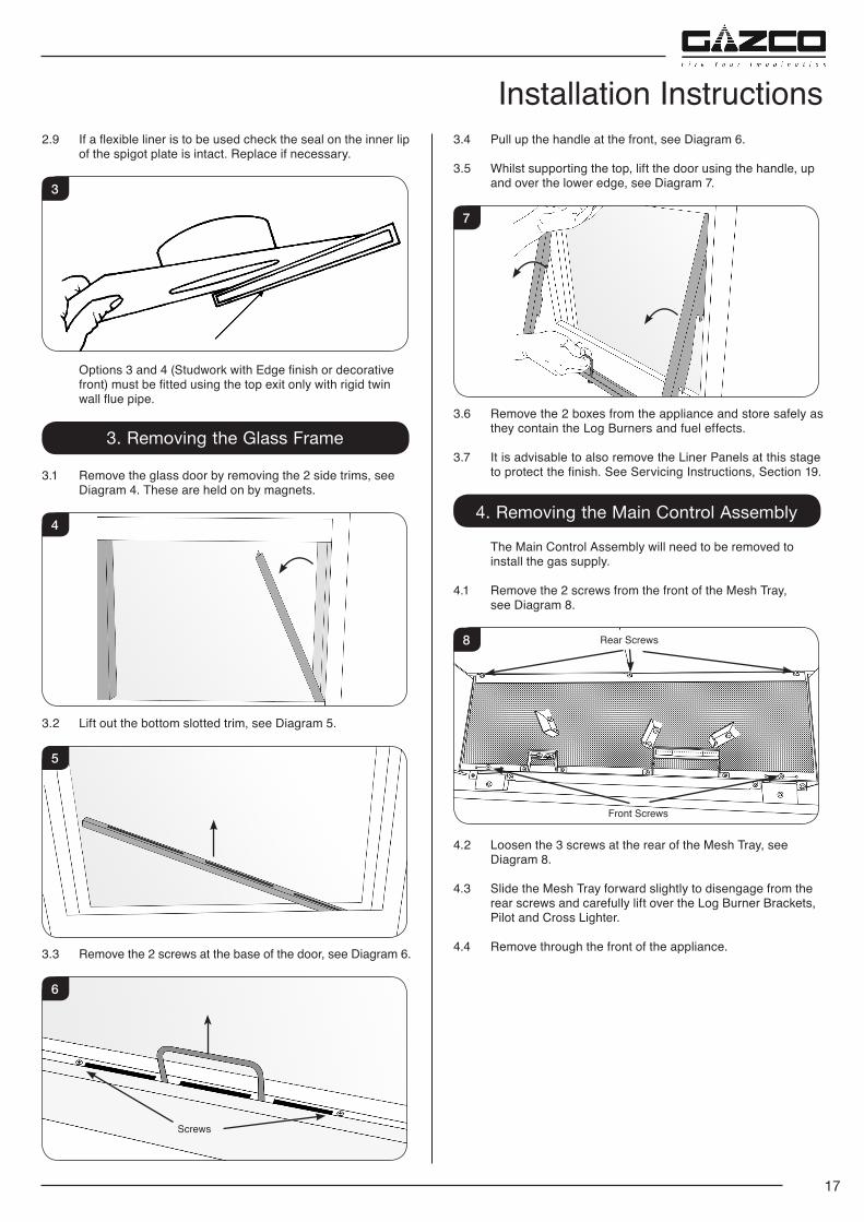
3.4 Pull up the handle at the front, see Diagram 6.
3.5 Whilst supporting the top, lift the door using the handle, up and over the lower edge, see Diagram 7.
7
3.6 Remove the 2 boxes from the appliance and store safely as they contain the Log Burners and fuel effects.
3.7 It is advisable to also remove the Liner Panels at this stage to protect the finish. See Servicing Instructions, Section 19.
4. Removing the Main Control Assembly
The Main Control Assembly will need to be removed to install the gas supply.
4.1 Remove the 2 screws from the front of the Mesh Tray, see Diagram 8.
8 Rear Screws
Front Screws
4.2 Loosen the 3 screws at the rear of the Mesh Tray, see Diagram 8.
4.3 Slide the Mesh Tray forward slightly to disengage from the rear screws and carefully lift over the Log Burner Brackets, Pilot and Cross Lighter.
4.4 Remove through the front of the appliance.
18
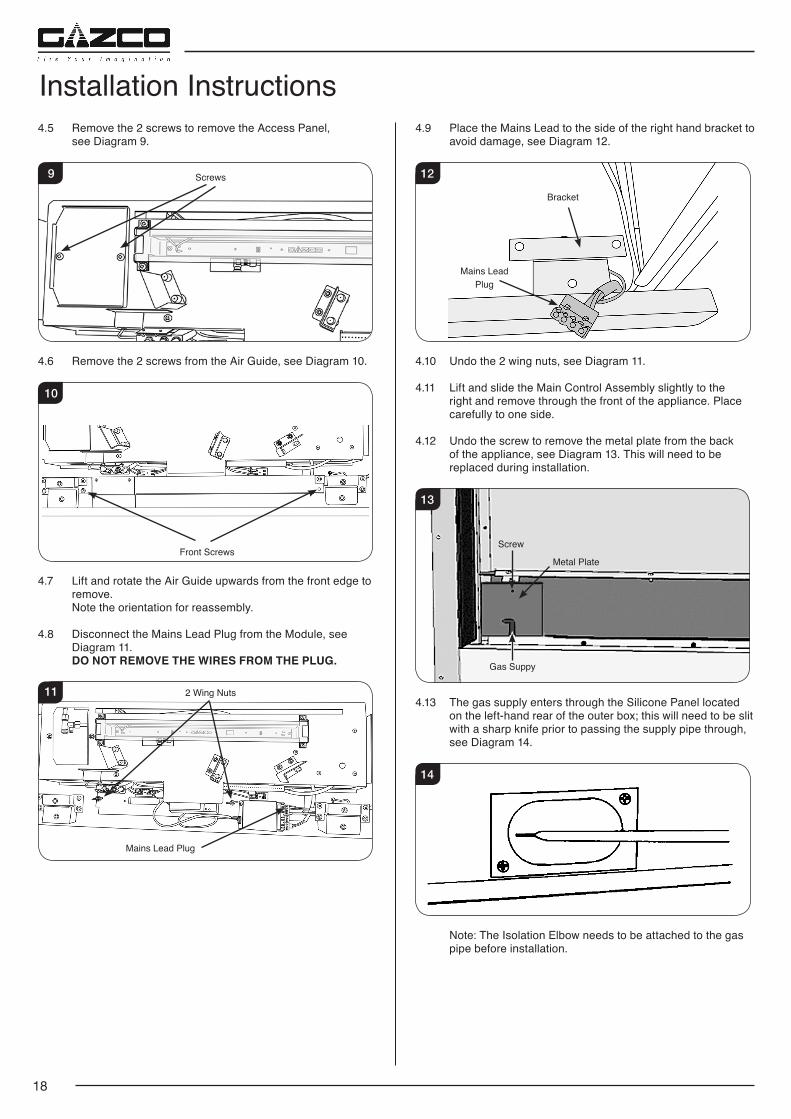
Installation Instructions4.5 Remove the 2 screws to remove the Access Panel,
see Diagram 9.
9 Screws
4.6 Remove the 2 screws from the Air Guide, see Diagram 10.
10
Front Screws
4.7 Lift and rotate the Air Guide upwards from the front edge to remove.
Note the orientation for reassembly.
4.8 Disconnect the Mains Lead Plug from the Module, see Diagram 11.
DO NOT REMOVE THE WIRES FROM THE PLUG.
11
Mains Lead Plug
2 Wing Nuts
4.9 Place the Mains Lead to the side of the right hand bracket to avoid damage, see Diagram 12.
12
Mains Lead Plug
Bracket
4.10 Undo the 2 wing nuts, see Diagram 11.
4.11 Lift and slide the Main Control Assembly slightly to the right and remove through the front of the appliance. Place carefully to one side.
4.12 Undo the screw to remove the metal plate from the back of the appliance, see Diagram 13. This will need to be replaced during installation.
13
Screw
Metal Plate
Gas Suppy
4.13 The gas supply enters through the Silicone Panel located on the left-hand rear of the outer box; this will need to be slit with a sharp knife prior to passing the supply pipe through, see Diagram 14.
14
Note: The Isolation Elbow needs to be attached to the gas pipe before installation.
19
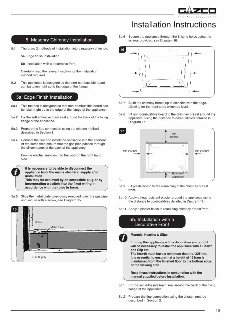
Installation Instructions5. Masonry Chimney Installation
5.1 There are 2 methods of installation into a masonry chimney:
5a. Edge finish Installation.
5b. Installation with a decorative front.
Carefully read the relevant section for the installation method required.
5.2 This appliance is designed so that non-combustible board can be taken right up to the edge of the flange.
5a. Edge Finish Installation
5a.1 This method is designed so that non-combustible board can be taken right up to the edge of the flange of the appliance.
5a.2 Fix the self adhesive foam seal around the back of the fixing flange of the appliance.
5a.3 Prepare the flue connection using the chosen method described in Section 2.
5a.4 Connect the flue and install the appliance into the aperture. At the same time ensure that the gas pipe passes through
the silicon panel at the back of the appliance.
Provide electric services into the void on the right hand side.
It is necessary to be able to disconnect the appliance from the mains electrical supply after installation.
This may be achieved by an accessible plug or by incorporating a switch into the fixed wiring in accordance with the rules in force.
5a.5 Slide the metal plate, previously removed, over the gas pipe
and secure with a screw, see Diagram 15.
15
Screw
Metal Plate
Gas Supply
5a.6 Secure the appliance through the 6 fixing holes using the screws provided, see Diagram 16.
16
5a.7 Build the chimney breast up to coincide with the edge, allowing for the front to be skimmed level.
5a.8 Fit non-combustible board to the chimney breast around the appliance, using the distance to combustibles detailed in Diagram 17.
17Min
400mm
Bottom of Appliance
Min 200mmMin 200mm
5a.9 Fit plasterboard to the remaining of the chimney breast front.
5a.10 Apply a heat resistant plaster around the appliance using the distance to combustibles detailed in Diagram 17.
5a.11 Apply a plaster finish to remaining chimney breast front.
5b. Installation with a Decorative Front
Mantels, Hearths & Slips
If fitting this appliance with a decorative surround it will be necessary to install the appliance with a Hearth and Slip set. The hearth must have a minimum depth of 225mm. It is essential to ensure that a height of 123mm is maintained from the finished floor to the bottom edge of the viewing area.
Read these instructions in conjunction with the manual supplied before installation.
5b.1 Fix the self adhesive foam seal around the back of the fixing flange of the appliance.
5b.2 Prepare the flue connection using the chosen method described in Section 2.
20
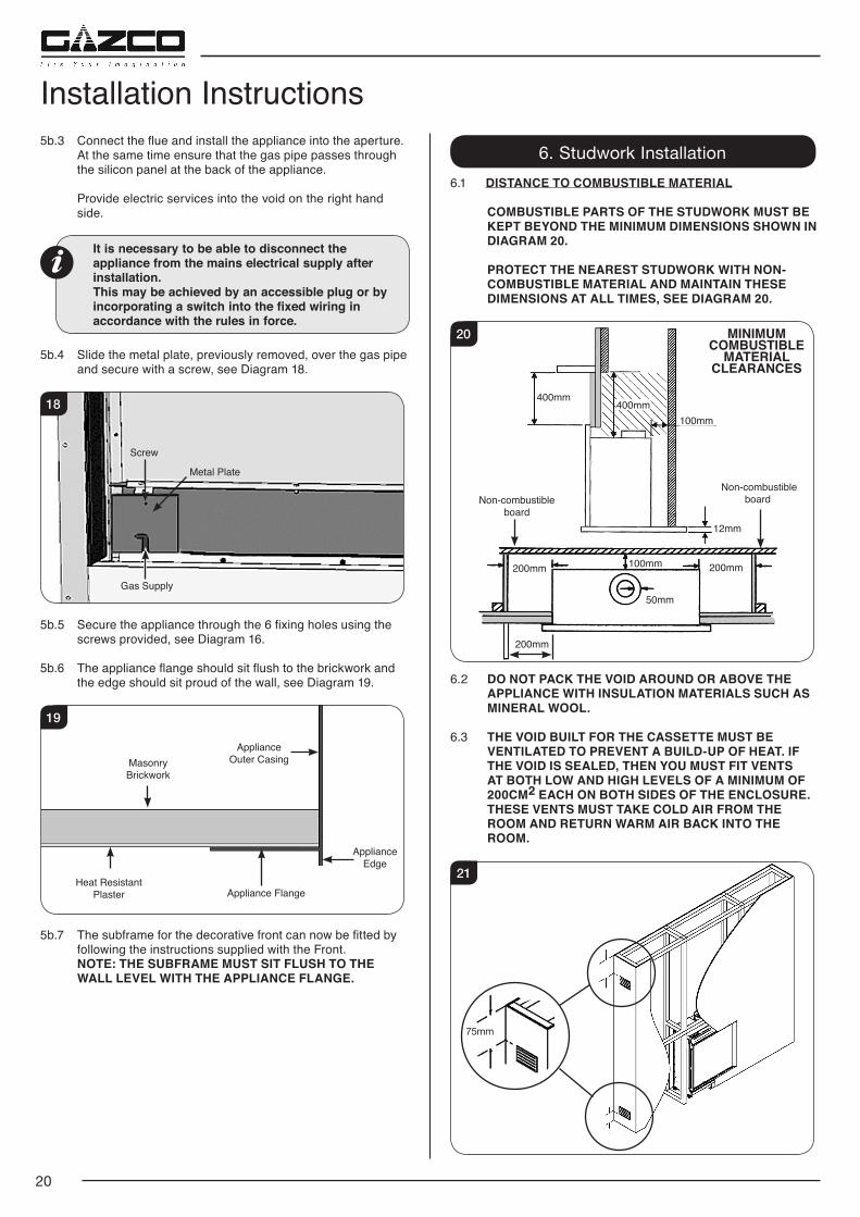
Installation Instructions5b.3 Connect the flue and install the appliance into the aperture.
At the same time ensure that the gas pipe passes through the silicon panel at the back of the appliance.
Provide electric services into the void on the right hand side.
It is necessary to be able to disconnect the appliance from the mains electrical supply after installation.
This may be achieved by an accessible plug or by incorporating a switch into the fixed wiring in accordance with the rules in force.
5b.4 Slide the metal plate, previously removed, over the gas pipe
and secure with a screw, see Diagram 18.
18
Screw
Metal Plate
Gas Supply
5b.5 Secure the appliance through the 6 fixing holes using the screws provided, see Diagram 16.
5b.6 The appliance flange should sit flush to the brickwork and the edge should sit proud of the wall, see Diagram 19.
19
Appliance Edge
Masonry Brickwork
ApplianceOuter Casing
Heat Resistant Plaster Appliance Flange
5b.7 The subframe for the decorative front can now be fitted by following the instructions supplied with the Front.
NOTE: THE SUBFRAME MUST SIT FLUSH TO THE WALL LEVEL WITH THE APPLIANCE FLANGE.
6. Studwork Installation6.1 DISTANCE TO COMBUSTIBLE MATERIAL
COMBUSTIBLE PARTS OF THE STUDWORK MUST BE KEPT BEYOND THE MINIMUM DIMENSIONS SHOWN IN DIAGRAM 20.
PROTECT THE NEAREST STUDWORK WITH NON-COMBUSTIBLE MATERIAL AND MAINTAIN THESE DIMENSIONS AT ALL TIMES, SEE DIAGRAM 20.
MINIMUMCOMBUSTIBLE
MATERIAL CLEARANCES
20
400mm100mm
400mm
100mm200mm
200mm
200mm
50mm
Non-combustible boardNon-combustible
board12mm
6.2 DO NOT PACK THE VOID AROUND OR ABOVE THE APPLIANCE WITH INSULATION MATERIALS SUCH AS MINERAL WOOL.
6.3 THE VOID BUILT FOR THE CASSETTE MUST BE VENTILATED TO PREVENT A BUILD-UP OF HEAT. IF THE VOID IS SEALED, THEN YOU MUST FIT VENTS AT BOTH LOW AND HIGH LEVELS OF A MINIMUM OF 200CM2 EACH ON BOTH SIDES OF THE ENCLOSURE. THESE VENTS MUST TAKE COLD AIR FROM THE ROOM AND RETURN WARM AIR BACK INTO THE ROOM.
21
75mm
21
Installation Instructions6.4 ALTERNATIVELY FOR THE HIGH VENTILATION THE
ENCLOSURE CAN BE CONSTRUCTED TO LEAVE A GAP BETWEEN THE TOP OF THE WALL AND THE CEILING GIVING THE REQUIRED VENTILATION AREA OR GREATER.
6.5 AN ACCESS HATCH MUST BE LEFT IN THE SIDE OF THE CHIMNEY BREAST FOR FUTURE SERVICING AND INSPECTION OF THE FLUE AND APPLIANCE.
This installation is Top Exit only. Use only a rigid twin wall flue pipe.
6.6 There are 2 methods of installation into a studwork chimney:
6a. Edge finish Installation.
6b. Installation with a decorative front.
Carefully read the relevant section for the installation method required.
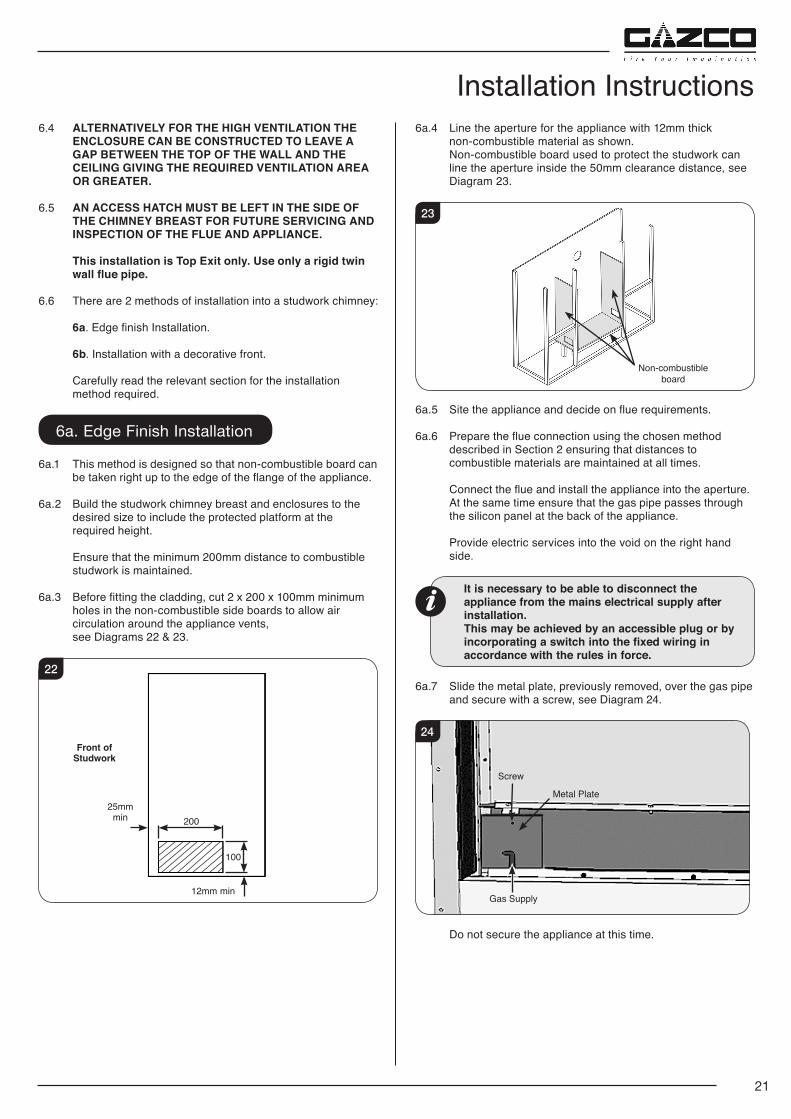
6a. Edge Finish Installation
6a.1 This method is designed so that non-combustible board can be taken right up to the edge of the flange of the appliance.
6a.2 Build the studwork chimney breast and enclosures to the desired size to include the protected platform at the required height.
Ensure that the minimum 200mm distance to combustible studwork is maintained.
6a.3 Before fitting the cladding, cut 2 x 200 x 100mm minimum holes in the non-combustible side boards to allow air circulation around the appliance vents, see Diagrams 22 & 23.
22
25mm min
12mm min
100
200
Front of Studwork
6a.4 Line the aperture for the appliance with 12mm thick non-combustible material as shown.
Non-combustible board used to protect the studwork can line the aperture inside the 50mm clearance distance, see Diagram 23.
23
Non-combustible board
6a.5 Site the appliance and decide on flue requirements.
6a.6 Prepare the flue connection using the chosen method described in Section 2 ensuring that distances to combustible materials are maintained at all times.
Connect the flue and install the appliance into the aperture. At the same time ensure that the gas pipe passes through the silicon panel at the back of the appliance.
Provide electric services into the void on the right hand
side.
It is necessary to be able to disconnect the appliance from the mains electrical supply after installation.
This may be achieved by an accessible plug or by incorporating a switch into the fixed wiring in accordance with the rules in force.
6a.7 Slide the metal plate, previously removed, over the gas pipe
and secure with a screw, see Diagram 24.
24
Screw
Metal Plate
Gas Supply
Do not secure the appliance at this time.
22
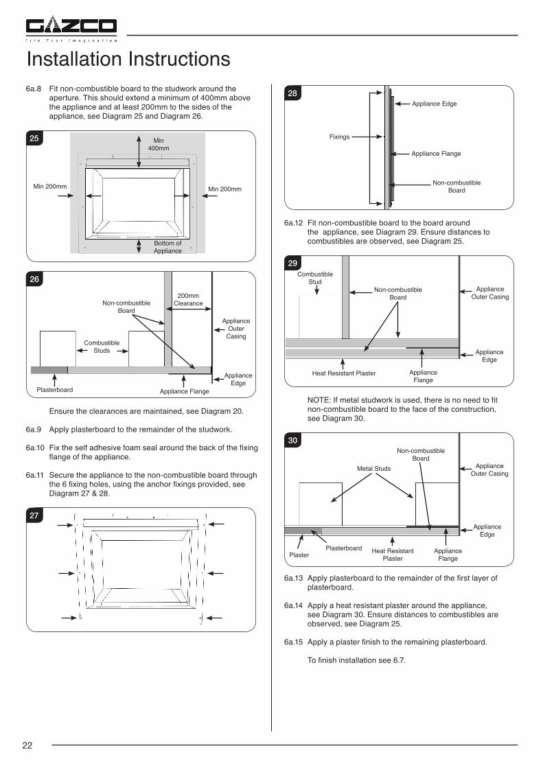
Installation Instructions6a.8 Fit non-combustible board to the studwork around the
aperture. This should extend a minimum of 400mm above the appliance and at least 200mm to the sides of the appliance, see Diagram 25 and Diagram 26.
25 Min 400mm
Bottom of Appliance
Min 200mmMin 200mm
26
Non-combustibleBoard
ApplianceOuter
Casing
Appliance Edge
200mmClearance
CombustibleStuds
Plasterboard Appliance Flange
Ensure the clearances are maintained, see Diagram 20.
6a.9 Apply plasterboard to the remainder of the studwork.
6a.10 Fix the self adhesive foam seal around the back of the fixing flange of the appliance.
6a.11 Secure the appliance to the non-combustible board through the 6 fixing holes, using the anchor fixings provided, see Diagram 27 & 28.
27
28Appliance Edge
Appliance Flange
Non-combustibleBoard
Fixings
6a.12 Fit non-combustible board to the board around the appliance, see Diagram 29. Ensure distances to combustibles are observed, see Diagram 25.
29Combustible
StudNon-combustible
BoardAppliance
Outer Casing
Appliance Edge
Heat Resistant Plaster Appliance Flange
NOTE: If metal studwork is used, there is no need to fit non-combustible board to the face of the construction, see Diagram 30.
30
Metal Studs
Non-combustibleBoard
ApplianceOuter Casing
Appliance Edge
Plasterboard Heat Resistant Plaster
Appliance FlangePlaster
6a.13 Apply plasterboard to the remainder of the first layer of plasterboard.
6a.14 Apply a heat resistant plaster around the appliance, see Diagram 30. Ensure distances to combustibles are observed, see Diagram 25.
6a.15 Apply a plaster finish to the remaining plasterboard.
To finish installation see 6.7.
23
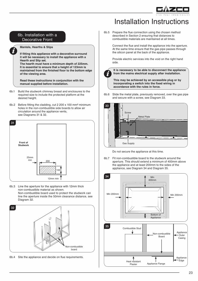
Installation Instructions6b. Installation with a
Decorative FrontMantels, Hearths & Slips
If fitting this appliance with a decorative surround it will be necessary to install the appliance with a Hearth and Slip set. The hearth must have a minimum depth of 225mm. It is essential to ensure that a height of 123mm is maintained from the finished floor to the bottom edge of the viewing area.
Read these instructions in conjunction with the manual supplied before installation.
6b.1 Build the studwork chimney breast and enclosures to the required size to include the protected platform at the desired height.
6b.2 Before fitting the cladding, cut 2 200 x 100 mm² minimum holes in the non-combustible side boards to allow air circulation around the appliance vents, see Diagrams 31 & 32.
31
25mm min
12mm min
100
200
Front of Studwork
6b.3 Line the aperture for the appliance with 12mm thick non-combustible material as shown.
Non-combustible board used to protect the studwork can line the aperture inside the 50mm clearance distance, see Diagram 32.
32
Non-combustible board
6b.4 Site the appliance and decide on flue requirements.
6b.5 Prepare the flue connection using the chosen method described in Section 2 ensuring that distances to combustible materials are maintained at all times.
Connect the flue and install the appliance into the aperture. At the same time ensure that the gas pipe passes through the silicon panel at the back of the appliance.
Provide electric services into the void on the right hand side.
It is necessary to be able to disconnect the appliance from the mains electrical supply after installation.
This may be achieved by an accessible plug or by incorporating a switch into the fixed wiring in accordance with the rules in force.
6b.6 Slide the metal plate, previously removed, over the gas pipe
and secure with a screw, see Diagram 33.
33
ScrewMetal Plate
Gas Supply
Do not secure the appliance at this time.
6b.7 Fit non-combustible board to the studwork around the aperture. This should extend a minimum of 400mm above the appliance and at least 200mm to the sides of the appliance, see Diagram 34 and Diagram 35.
34 Min 400mm
Bottom of Appliance
Min 200mmMin 200mm
35
Non-combustibleBoard
ApplianceOuter
Casing
Appliance Edge
Combustible Stud
Heat resistant Plaster Appliance Flange
24
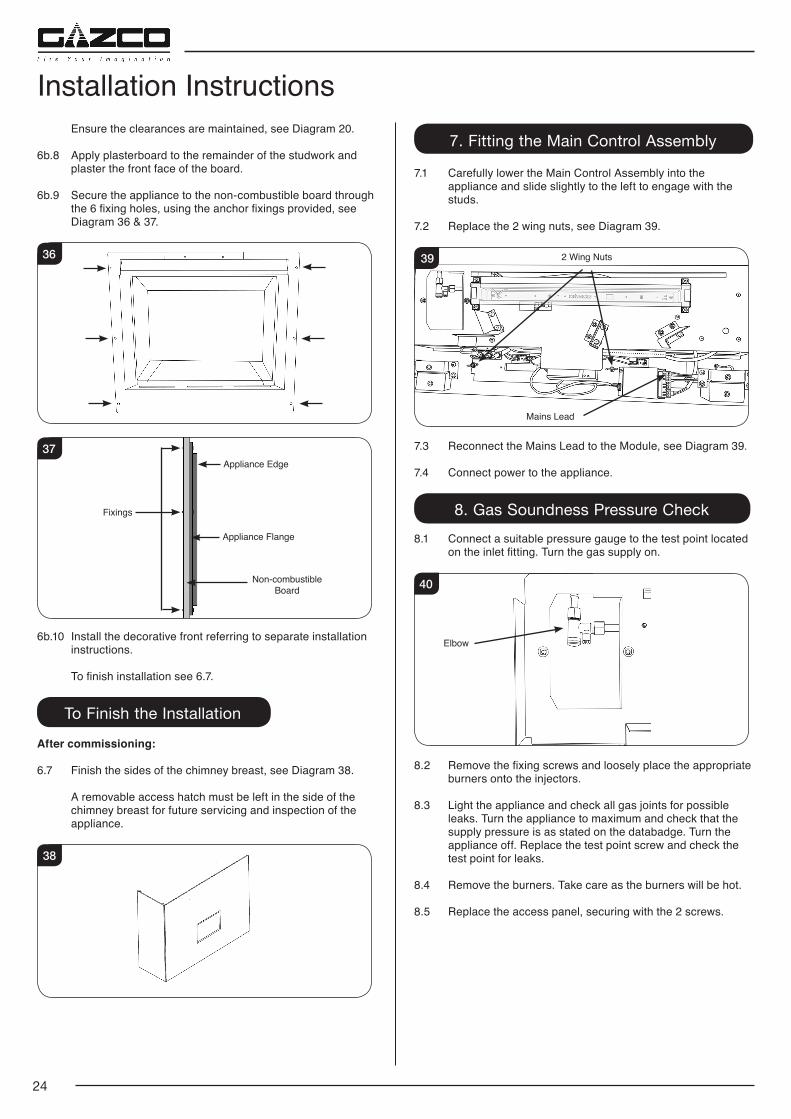
Ensure the clearances are maintained, see Diagram 20.
6b.8 Apply plasterboard to the remainder of the studwork and plaster the front face of the board.
6b.9 Secure the appliance to the non-combustible board through the 6 fixing holes, using the anchor fixings provided, see Diagram 36 & 37.
36
37Appliance Edge
Appliance Flange
Non-combustibleBoard
Fixings
6b.10 Install the decorative front referring to separate installation instructions.
To finish installation see 6.7.
To Finish the Installation
After commissioning:
6.7 Finish the sides of the chimney breast, see Diagram 38.
A removable access hatch must be left in the side of the chimney breast for future servicing and inspection of the appliance.
38
Installation Instructions7. Fitting the Main Control Assembly
7.1 Carefully lower the Main Control Assembly into the appliance and slide slightly to the left to engage with the studs.
7.2 Replace the 2 wing nuts, see Diagram 39.
39
Mains Lead
2 Wing Nuts
7.3 Reconnect the Mains Lead to the Module, see Diagram 39.
7.4 Connect power to the appliance.
8. Gas Soundness Pressure Check8.1 Connect a suitable pressure gauge to the test point located
on the inlet fitting. Turn the gas supply on.
40
Elbow
8.2 Remove the fixing screws and loosely place the appropriate burners onto the injectors.
8.3 Light the appliance and check all gas joints for possible leaks. Turn the appliance to maximum and check that the supply pressure is as stated on the databadge. Turn the appliance off. Replace the test point screw and check the test point for leaks.
8.4 Remove the burners. Take care as the burners will be hot.
8.5 Replace the access panel, securing with the 2 screws.
25
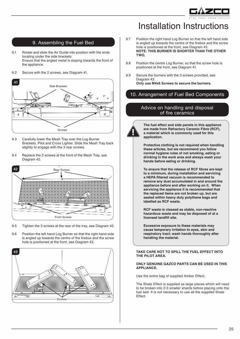
Installation Instructions9. Assembling the Fuel Bed
9.1 Rotate and slide the Air Guide into position with the ends locating under the side brackets
Ensure that the angled metal is sloping towards the front of the appliance.
9.2 Secure with the 2 screws, see Diagram 41.
41
Screws
Side Brackets
9.3 Carefully lower the Mesh Tray over the Log Burner Brackets, Pilot and Cross Lighter. Slide the Mesh Tray back slightly to engage with the 3 rear screws.
9.4 Replace the 2 screws at the front of the Mesh Tray, see Diagram 42.
42 Rear Screws
Front Screws
9.5 Tighten the 3 screws at the rear of the tray, see Diagram 42.
9.6 Position the left hand Log Burner so that the right hand side is angled up towards the centre of the firebox and the screw hole is positioned at the front, see Diagram 43.
43
Screws
9.7 Position the right hand Log Burner so that the left hand side is angled up towards the centre of the firebox and the screw hole is positioned at the front, see Diagram 43.
NOTE: THIS BURNER IS SHORTER THAN THE OTHER TWO.
9.8 Position the centre Log Burner, so that the screw hole is positioned at the front, see Diagram 41.
9.9 Secure the burners with the 3 screws provided, see Diagram 43. Only use M4x6 Screws to secure the burners.
10. Arrangement of Fuel Bed Components
Advice on handling and disposal of fire ceramics
The fuel effect and side panels in this appliance are made from Refractory Ceramic Fibre (RCF), a material which is commonly used for this application.
Protective clothing is not required when handling these articles, but we recommend you follow normal hygiene rules of not smoking, eating or drinking in the work area and always wash your hands before eating or drinking.
To ensure that the release of RCF fibres are kept to a minimum, during installation and servicing a HEPA filtered vacuum is recommended to remove any dust accumulated in and around the appliance before and after working on it. When servicing the appliance it is recommended that the replaced items are not broken up, but are sealed within heavy duty polythene bags and labelled as RCF waste.
RCF waste is classed as stable, non-reactive hazardous waste and may be disposed of at a licensed landfill site.
Excessive exposure to these materials may cause temporary irritation to eyes, skin and respiratory tract; wash hands thoroughly after handling the material.
TAKE CARE NOT TO SPILL THE FUEL EFFECT INTO THE PILOT AREA.
ONLY GENUINE GAZCO PARTS CAN BE USED IN THIS APPLIANCE.
Use the entire bag of supplied Amber Effect.
The Shale Effect is supplied as large pieces which will need to be broken into 2-3 smaller shards before placing onto the fuel bed. It is not necessary to use all the supplied Shale Effect.
26
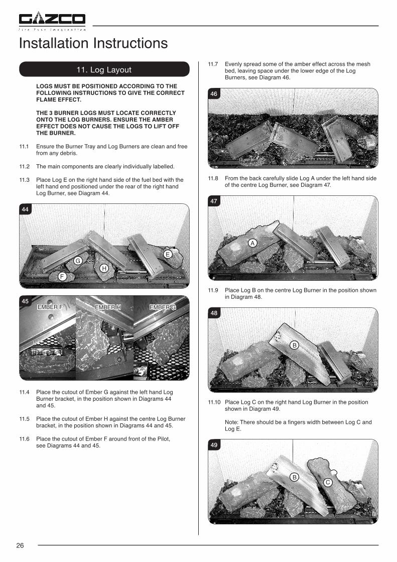
Installation Instructions11. Log Layout
LOGS MUST BE POSITIONED ACCORDING TO THE FOLLOWING INSTRUCTIONS TO GIVE THE CORRECT FLAME EFFECT.
THE 3 BURNER LOGS MUST LOCATE CORRECTLY ONTO THE LOG BURNERS. ENSURE THE AMBER EFFECT DOES NOT CAUSE THE LOGS TO LIFT OFF THE BURNER.
11.1 Ensure the Burner Tray and Log Burners are clean and free from any debris.
11.2 The main components are clearly individually labelled.
11.3 Place Log E on the right hand side of the fuel bed with the left hand end positioned under the rear of the right hand Log Burner, see Diagram 44.
44
E
HG
F
45EMBER H EMBER GEMBER F
11.4 Place the cutout of Ember G against the left hand Log Burner bracket, in the position shown in Diagrams 44
and 45.
11.5 Place the cutout of Ember H against the centre Log Burner bracket, in the position shown in Diagrams 44 and 45.
11.6 Place the cutout of Ember F around front of the Pilot, see Diagrams 44 and 45.
11.7 Evenly spread some of the amber effect across the mesh bed, leaving space under the lower edge of the Log Burners, see Diagram 46.
46
11.8 From the back carefully slide Log A under the left hand side of the centre Log Burner, see Diagram 47.
47
A
11.9 Place Log B on the centre Log Burner in the position shown in Diagram 48.
48
B
11.10 Place Log C on the right hand Log Burner in the position shown in Diagram 49.
Note: There should be a fingers width between Log C and Log E.
49
CB
27
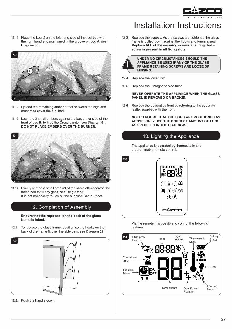
Installation Instructions11.11 Place the Log D on the left hand side of the fuel bed with
the right hand end positioned in the groove on Log A, see Diagram 50.
50
D
11.12 Spread the remaining amber effect between the logs and embers to cover the fuel bed.
11.13 Lean the 2 small embers against the bar, either side of the front of Log B, to hide the Cross Lighter, see Diagram 51.
DO NOT PLACE EMBERS OVER THE BURNER.
51
11.14 Evenly spread a small amount of the shale effect across the mesh bed to fill any gaps, see Diagram 51.
It is not necessary to use all the supplied Shale Effect.
12. Completion of Assembly Ensure that the rope seal on the back of the glass
frame is intact.
12.1 To replace the glass frame, position so the hooks on the back of the frame fit over the side pins, see Diagram 52.
52
12.2 Push the handle down.
12.3 Replace the screws. As the screws are tightened the glass frame is pulled down against the hooks and forms a seal.
Replace ALL of the securing screws ensuring that a screw is present in all fixing slots.
UNDER NO CIRCUMSTANCES SHOULD THE APPLIANCE BE USED IF ANY OF THE GLASS FRAME RETAINING SCREWS ARE LOOSE OR MISSING.
12.4 Replace the lower trim.
12.5 Replace the 2 magnetic side trims.
NEVER OPERATE THE APPLIANCE WHEN THE GLASS PANEL IS REMOVED OR BROKEN.
12.6 Replace the decorative front by referring to the separate leaflet supplied with the front.
NOTE: ENSURE THAT THE LOGS ARE POSITIONED AS ABOVE. ONLY USE THE CORRECT AMOUNT OF LOGS AS SPECIFIED IN THE DIAGRAMS.
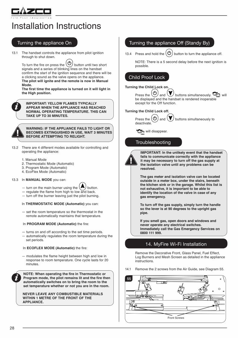
13. Lighting the Appliance
The appliance is operated by thermostatic and programmable remote control.
53
Via the remote it is possible to control the following features:
54 Child proof lock Time
Light
EcoFlex Mode
Signal Indicator Thermostatic
Mode
Dual Burner Fucntion
Temperature
Program Mode
Countdown timer
Battery Status
28
Installation InstructionsTurning the appliance On
13.1 The handset controls the appliance from pilot ignition through to shut down.
To turn the fire on press the button until two short signals and a series of blinking lines on the handset confirm the start of the ignition sequence and there will be a clicking sound as the valve opens on the appliance.
The pilot will ignite and the remote is now in Manual Mode.
The first time the appliance is turned on it will light in the High position.
IMPORTANT: YELLOW FLAMES TYPICALLY APPEAR WHEN THE APPLIANCE HAS REACHED NORMAL OPERATING TEMPERATURE. THIS CAN TAKE UP TO 30 MINUTES.
WARNING: IF THE APPLIANCE FAILS TO LIGHT OR BECOMES EXTINGUISHED IN USE, WAIT 3 MINUTES BEFORE ATTEMPTING TO RELIGHT.
13.2 There are 4 different modes available for controlling and operating the appliance:
1. Manual Mode 2. Thermostatic Mode (Automatic) 3. Program Mode (Automatic) 4. EcoFlex Mode (Automatic)
13.3 In MANUAL MODE you can:
— turn on the main burner using the button. — regulate the flame from high to low and back. — turn off the burner leaving just the pilot burning.
In THERMOSTATIC MODE (Automatic) you can:
— set the room temperature so the thermostat in the remote automatically maintains that temperature.
In PROGRAM MODE (Automatic) the fire:
— turns on and off according to the set time periods. — automatically regulates the room temperature during the
set periods.
In ECOFLEX MODE (Automatic) the fire:
— modulates the flame height between high and low in response to room temperature. One cycle lasts for 20 minutes.
NOTE: When operating the fire in Thermostatic or Program mode, the pilot remains lit and the fire then automatically switches on to bring the room to the set temperature whether or not you are in the room.
NEVER LEAVE ANY COMBUSTIBLE MATERIALS WITHIN 1 METRE OF THE FRONT OF THE APPLIANCE.
Turning the appliance Off (Standy By)
13.4 Press and hold the button to turn the appliance off.
NOTE: There is a 5 second delay before the next ignition is possible.
Child Proof Lock
Turning the Child Lock on.
Press the and buttons simultaneously. will be displayed and the handset is rendered inoperable except for the Off function.
Turning the Child Lock off.
Press the and buttons simultaneously to deactivate.
will disappear.
Troubleshooting
IMPORTANT: In the unlikely event that the handset fails to communicate correctly with the appliance it may be necessary to turn off the gas supply at the isolation valve until any problems can be resolved.
The gas meter and isolation valve can be located outside in a meter box, under the stairs, beneath the kitchen sink or in the garage. Whilst this list is not exhaustive, it is important to be able to identify the location of the valve in case of any gas emergency.
To turn off the gas supply, simply turn the handle so the lever is at 90 degrees to the upright gas pipe.
If you smell gas, open doors and windows and never operate any electrical switches. Immediately call the Gas Emergency Services on 0800 111 999.
14. MyFire Wi-Fi Installation Remove the Decorative Front, Glass Panel, Fuel Effect,
Log Burners and Mesh Screen as detailed in the appliance instructions.
14.1 Remove the 2 screws from the Air Guide, see Diagram 55.
55
Front Screws
29
14.2 Lift and rotate the Air Guide upwards from the front edge to remove.
Note the orientation for reassembly of the air guide.
14.3 Secure the velcro pads to the underside of the Wi-Fi module and position in the allocated position, see Diagrams 56 & 57.
56
LED'S
57
When satisfied with the position remove the backing from the velcro pad and secure in place.
Ensure the Wi-Fi module butts up to the folded return beside the LED bar & clearance is left between the front edge of the fire and the Wi-Fi module.
14.4 Using the Wi-Fi cable Connect the Wi-Fi module to the receiver module, see Diagram 58.
Gazco recommend running the cable along the front edge of the fire to avoid obstruction of any internal components.
58
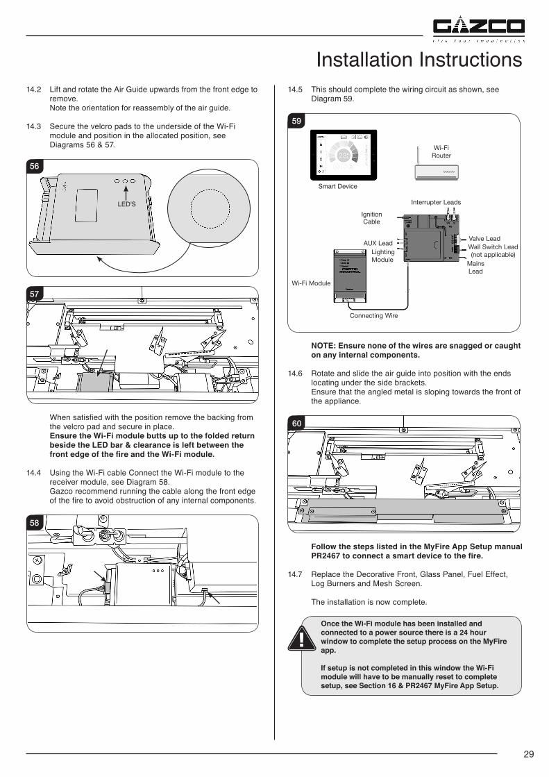
14.5 This should complete the wiring circuit as shown, see Diagram 59.
Wi-Fi Router
Interrupter Leads
Wi-Fi Module
AUX Lead
59
Valve Lead
Ignition Cable
Connecting Wire
Lighting Module Mains
Lead
Smart Device
Wall Switch Lead (not applicable)
NOTE: Ensure none of the wires are snagged or caught on any internal components.
14.6 Rotate and slide the air guide into position with the ends locating under the side brackets.
Ensure that the angled metal is sloping towards the front of the appliance.
60
Follow the steps listed in the MyFire App Setup manual PR2467 to connect a smart device to the fire.
14.7 Replace the Decorative Front, Glass Panel, Fuel Effect, Log Burners and Mesh Screen.
The installation is now complete.
Once the Wi-Fi module has been installed and connected to a power source there is a 24 hour window to complete the setup process on the MyFire app.
If setup is not completed in this window the Wi-Fi module will have to be manually reset to complete setup, see Section 16 & PR2467 MyFire App Setup.
Installation Instructions
30
15. Accessing the Wi-Fi Module Once installed, the Wi-Fi module can be accessed by
following the below instruction.
15.1 Remove the Glass Frame, see Instructions provided with appliance model.
15.2 Remove the two screws securing the Wi-Fi Module access panel and slide across, see Diagram 61.
61
The Wi-Fi module is now accessible, see Diagram 62.
62
16. MyFire Wi-Fi Set Up & Troubleshooting16.1 The MyFire Wi-Fi box must be wired according to the
MyFire set up diagram (see Diagram 59) and connected to the receiver, which is in turn connected to the mains power.
Ensure the device is running the most up to date operating system as older models may not be compatible with the MyFire App.
After 30 seconds the MyFire Box goes into Access Point Mode (Green LED flashes). See MyFire App instructions supplied and configure the router.
16.2 The following things can affect the Wi-Fi signal on the appliance:
1. Multiple users on the same Wi-Fi channel may interfere
with the data transfer. Press the reset button on the MyFire Wi-Fi box for 1 second to change the current channel.
2. If the MyFire Wi-Fi box is not connected to the receiver or is not used it will leave Access Point Mode after 24 hours.
3. If there are multiple fireplaces in the household using MyFire Wi-Fi boxes there must be a minimum of 600mm between them to avoid interference.
4. If there are any changes to the home network then the MyFire Wi-Fi set up must be repeated.
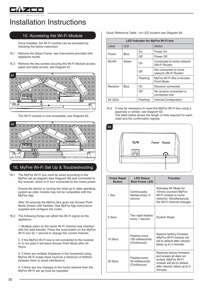
Installation InstructionsQuick Reference Table - for LED location see Diagram 56.
LED Indicator for MyFire Wi-Fi box
Label LED Status
Power BlueOn Power OnOff Power Off
WLAN Green On Connected to home network (Wi-Fi Router)
Off Not connected to home network (Wi-Fi Router)
Flashing MyFire Wi-Fi Box in Access Point Mode
Receiver Blue On Receiver connectedOff No receiver connected or
connection lostAll LEDs Flashing Internal Configuration
16.3 It may be necessary to reset the MyFire Wi-Fi box using a paperclip or similar, see Diagram 63.
The table below shows the length of time required for each reset and the confirmation signals.
63
Press Reset Button
LED StatusBlue Power LED
Function
1 SecContinuously flashes every ½ second
Activates AP Mode for 10mins (connect MyFire Wi-Fi module to home network). Simultaneously the Wi-Fi channel changes.
5 Secs Two rapid flashes every 1 second System Reset.
10 SecsFlashes every 100 milliseconds (Continuous)
Restore factory firmware (MyFire Wi-Fi module will set to default after reboot); takes up to 2 minutes.
20 SecsFlashes every 50 milliseconds (Continuous)
Restores factory firmware and erases all data not locked. (MyFire Wi-Fi module will set to default after reboot); takes up to 2 minutes.
31
1. Commissioning
1.1 Check the flame picture, log layout.
1.2 Check the gas pressure.
1.3 Close all door and windows in the room.
1.4 Ignite the appliance and operate on maximum for 5 minutes.
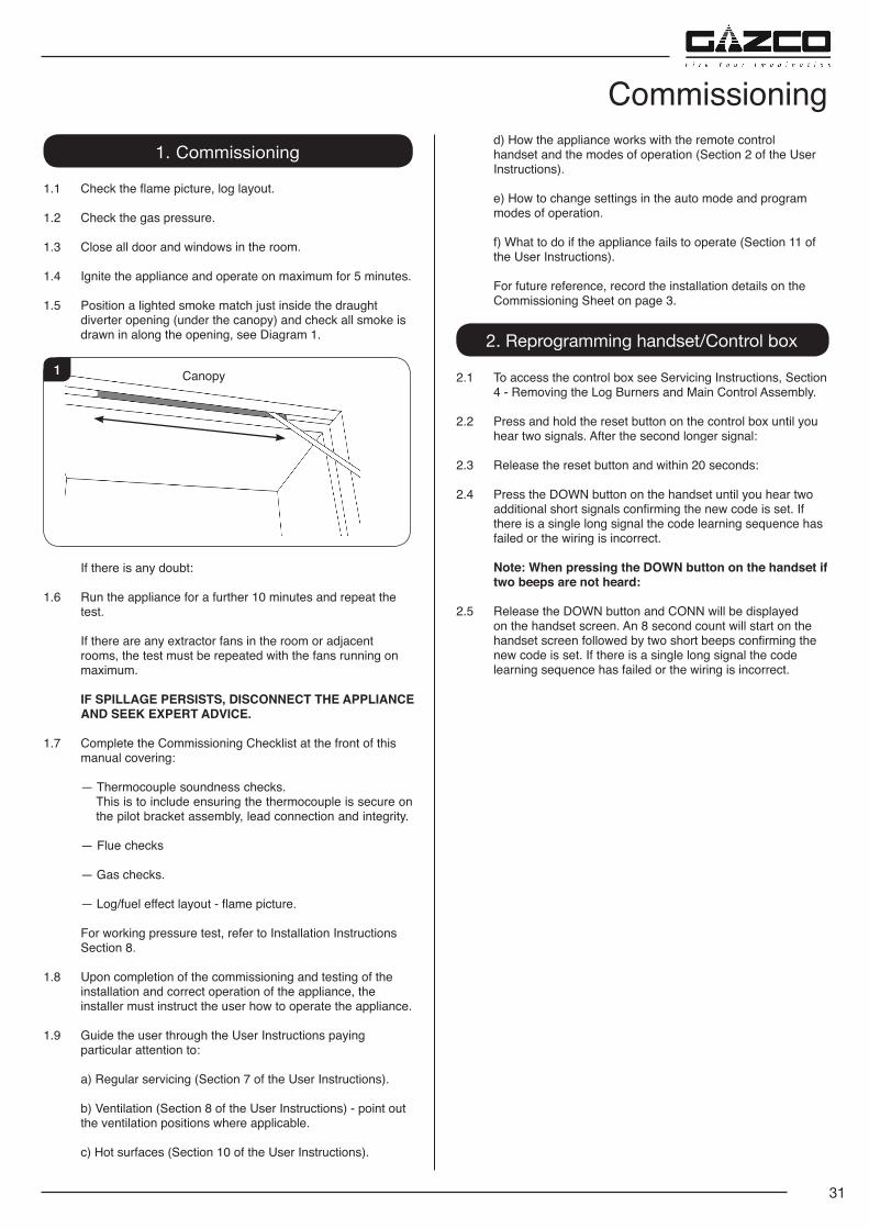
1.5 Position a lighted smoke match just inside the draught diverter opening (under the canopy) and check all smoke is drawn in along the opening, see Diagram 1.
1 Canopy
If there is any doubt:
1.6 Run the appliance for a further 10 minutes and repeat the test.
If there are any extractor fans in the room or adjacent rooms, the test must be repeated with the fans running on maximum.
IF SPILLAGE PERSISTS, DISCONNECT THE APPLIANCE AND SEEK EXPERT ADVICE.
1.7 Complete the Commissioning Checklist at the front of this manual covering:
— Thermocouple soundness checks. This is to include ensuring the thermocouple is secure on the pilot bracket assembly, lead connection and integrity.
— Flue checks
— Gas checks.
— Log/fuel effect layout - flame picture.
For working pressure test, refer to Installation Instructions Section 8.
1.8 Upon completion of the commissioning and testing of the installation and correct operation of the appliance, the installer must instruct the user how to operate the appliance.
1.9 Guide the user through the User Instructions paying particular attention to:
a) Regular servicing (Section 7 of the User Instructions).
b) Ventilation (Section 8 of the User Instructions) - point out the ventilation positions where applicable.
c) Hot surfaces (Section 10 of the User Instructions).
d) How the appliance works with the remote control handset and the modes of operation (Section 2 of the User Instructions).
e) How to change settings in the auto mode and program modes of operation.
f) What to do if the appliance fails to operate (Section 11 of the User Instructions).
For future reference, record the installation details on the Commissioning Sheet on page 3.
2. Reprogramming handset/Control box
2.1 To access the control box see Servicing Instructions, Section 4 - Removing the Log Burners and Main Control Assembly.
2.2 Press and hold the reset button on the control box until you hear two signals. After the second longer signal:
2.3 Release the reset button and within 20 seconds:
2.4 Press the DOWN button on the handset until you hear two additional short signals confirming the new code is set. If there is a single long signal the code learning sequence has failed or the wiring is incorrect.
Note: When pressing the DOWN button on the handset if two beeps are not heard:
2.5 Release the DOWN button and CONN will be displayed on the handset screen. An 8 second count will start on the handset screen followed by two short beeps confirming the new code is set. If there is a single long signal the code learning sequence has failed or the wiring is incorrect.
Commissioning
32
1. Servicing Requirements
IMPORTANT – The glass panel on this appliance should be checked for any signs of damage on the front face of the glass panel (scratches, scores, cracks or other surface defects). If damage is observed, the glass panel must be replaced and the appliance must not be used until a replacement is installed. Under no circumstances should the appliance be used if any damage is observed. Please isolate the appliance until a replacement glass panel has been obtained and installed. Replacement glass panels can be purchased from Gazco via the retailer from which the appliance was purchased or any other Gazco distributor.
This appliance must be serviced at least once a year by a competent person.
All tests must be carried out in accordance with the current GasSafe recommendations.
1.1 Before Testing:
— Conduct a gas soundness test for the property ensuring there are no leaks before servicing. — Check the operation of the appliance before testing.
1.2 Special checks:
— Clean the burner using a vacuum cleaner with a soft brush attachment. Ensure all debris is removed from the burner ports.
— Clean away lint or fluff from the pilot. — Clean away lint or fluff from under the burner. — Check the spark gap on the pilot is correct. — Check that the Pilot ignites correctly and Main Burner
cross lights smoothly. — Check debris collection space, see page 35. — Ensure that the glass frame is secured correctly and that
all retaining screws are in place.
1.3 Correct any faults found during the initial test.
1.4 Re-commission the appliance in accordance with Commissioning Procedures of these instructions.
1.5 Advise the customer of any remedial work undertaken.
Symptom Cause RemedyNo ignition, 5 second continuous tone (there may be several short beeps before)
Loose/damaged wire Check interrupter block and wires
No ignition, no tone, motor turns slightly when operated
Receiver board damaged Replace receiver
No pilot flame and control continues to spark
Thermocouple circuit wired incorrectly Correct wiring
Pilot lights, control continues to spark, valve shuts down after 10 - 30 seconds
1. No spark at pilot burner2. Loose/damaged wire
1. Rectify spark at pilot burner2. Check interrupter and wires
Rear burner can not be turned off - valve can be heard to operate.
Faulty Solenoid Valve
Replace Solenoid Valve
Rear burner can not be turned off - no beep or noise from solenoid
1. Faulty wire/ wire not connected. 2. Faulty receiver
1. Replace wire/ solenoid.2. Replace receiver
Electronic Control Valve Fault Analysis
Servicing InstructionsServicing/Fault Finding Charts
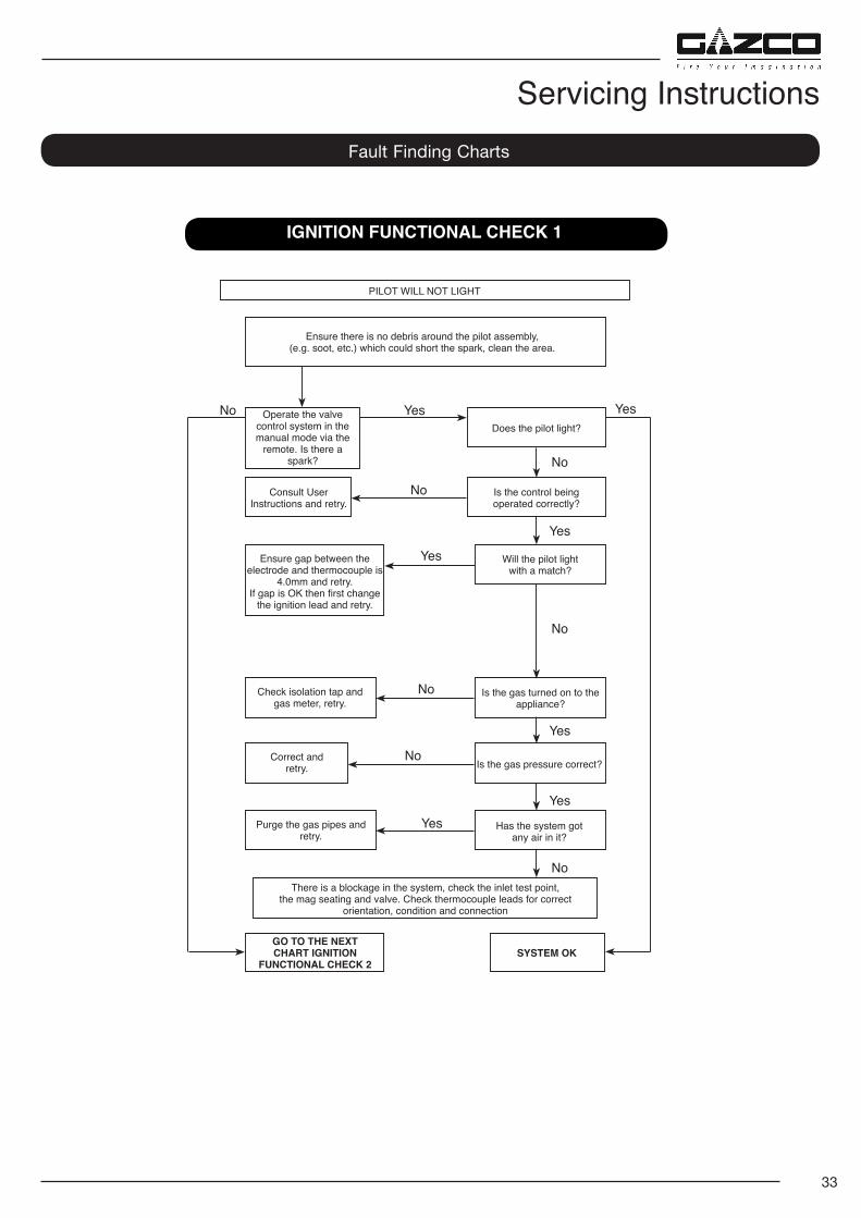
33
IGNITION FUNCTIONAL CHECK 1
PILOT WILL NOT LIGHT
Ensure there is no debris around the pilot assembly, (e.g. soot, etc.) which could short the spark, clean the area.
Operate the valve control system in the manual mode via the
remote. Is there a spark?
Consult User Instructions and retry.
Ensure gap between the electrode and thermocouple is
4.0mm and retry.If gap is OK then first change
the ignition lead and retry.
Check isolation tap and gas meter, retry.
Correct and retry.
Purge the gas pipes and retry.
GO TO THE NEXT CHART IGNITION
FUNCTIONAL CHECK 2SYSTEM OK
There is a blockage in the system, check the inlet test point, the mag seating and valve. Check thermocouple leads for correct
orientation, condition and connection
Is the gas turned on to the appliance?
Is the gas pressure correct?
Has the system got any air in it?
Does the pilot light?
Is the control being operated correctly?
Will the pilot light with a match?
No Yes
No
Yes
No
Yes
Yes
No
No
Yes
No
No
Yes
Yes
Servicing InstructionsFault Finding Charts
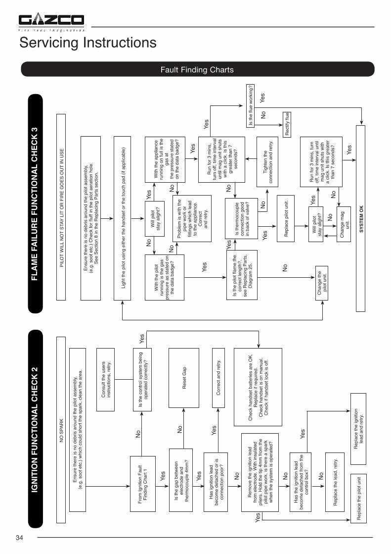
34
PILO
T W
ILL
NO
T ST
AY L
IT O
R F
IRE
GO
ES O
UT
IN U
SE
Ensu
re th
ere
is n
o de
bris
aro
und
the
pilo
t ass
embl
y, (e
.g. s
oot e
tc.)
Che
ck fo
r fluf
f in
the
pilo
t aer
atio
n ho
le.
See
Sect
ion
8 in
the
Rep
laci
ng P
arts
sec
tion.
Prob
lem
is w
ith th
e pi
pe w
ork
or
fittin
gs w
hich
lead
to
the
appl
ianc
e.
Cor
rect
an
d re
try.
Is th
erm
ocou
ple
conn
ectio
n go
od
in b
ack
of v
alve
?
Rep
lace
pilo
t uni
t.
Will
pilo
t st
ay a
light
?
Cha
nge
mag
un
it.
Is th
e pi
lot fl
ame
the
corre
ct le
ngth
?,
see
Rep
laci
ng P
arts
, D
iagr
am 2
5.
Cha
nge
the
pilo
t uni
t.
Will
pilo
t st
ay a
light
?W
ith th
e pi
lot
runn
ing
is th
e ga
s pr
essu
re a
s st
ated
on
the
data
bad
ge?
With
the
appl
ianc
e ru
nnin
g on
full
is th
e ga
s at
th
e pr
essu
re s
tate
d
on th
e da
ta b
adge
?
Run
for 3
min
s,
turn
off,
tim
e in
terv
al
until
mag
uni
t shu
ts
with
a c
lick.
Is th
is
grea
ter t
han
7 se
cond
s?
Run
for 3
min
s, tu
rn
off,
time
inte
rval
unt
il m
ag u
nit s
huts
with
a
clic
k. Is
this
gre
ater
th
an 7
sec
onds
?
Tigh
ten
the
co
nnec
tion
and
retry
.
No
No
No
No
No
No
Yes
SYST
EM O
K
Yes
Yes
Yes
Yes
No
Yes
Yes
No
Ligh
t the
pilo
t usi
ng e
ither
the
hand
set o
r the
touc
h pa
d (if
app
licab
le)
FLA
ME
FAIL
UR
E FU
NC
TIO
NA
L C
HEC
K 3
IGN
ITIO
N F
UN
CTI
ON
AL
CH
ECK
2
NO
SPA
RK
Ensu
re th
ere
is n
o de
bris
aro
und
the
pilo
t ass
embl
y, (e
.g. s
oot e
tc.)
whi
ch c
ould
sho
rt th
e sp
ark,
cle
an th
e ar
ea.
Con
sult
the
user
s in
stru
ctio
ns, r
etry
.
From
Igni
tion
Faul
t Fi
ndin
g C
hart
1
Is th
e ga
p be
twee
n el
ectro
de a
nd
ther
moc
oupl
e 4m
m?
Has
igni
tion
lead
be
com
e de
tach
ed o
r is
conn
ectio
n po
or?
Rem
ove
the
igni
tion
lead
fro
m e
lect
rode
. With
insu
late
d
plie
rs. H
old
the
tip 4
mm
from
the
pi
lot p
ipe
wor
k, is
ther
e a
spar
k
whe
n th
e sy
stem
is o
pera
ted?
Has
the
igni
tion
lead
be
com
e de
tach
ed fr
om th
e co
ntro
l box
?
Rep
lace
the
lead
, ret
ry.
Cor
rect
and
retry
.
Che
ck h
ands
et b
atte
ries
are
OK.
R
epla
ce if
requ
ired.
C
heck
han
dset
is o
n m
anua
l. C
heck
if h
ands
et lo
ck is
off.
Is th
e co
ntro
l sys
tem
bei
ng
oper
ated
cor
rect
ly?
Res
et G
ap
Yes
Yes
Yes
No
No
No
Yes
Yes
Yes
No N
o
Rep
lace
the
pilo
t uni
tR
epla
ce th
e ig
nitio
n le
ad a
nd re
try.
Is th
e flu
e w
orki
ng?
Rec
tify
flueNo
Yes
Yes
Fault Finding Charts
Servicing Instructions
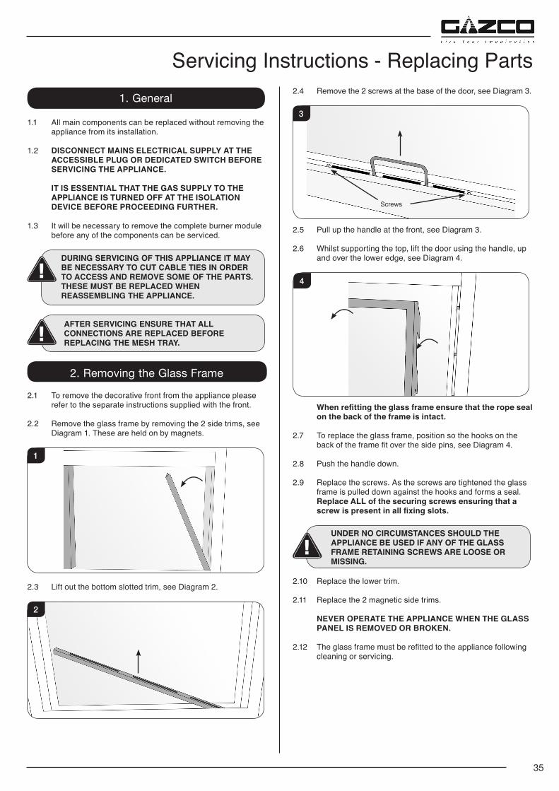
35
1. General
1.1 All main components can be replaced without removing the appliance from its installation.
1.2 DISCONNECT MAINS ELECTRICAL SUPPLY AT THE ACCESSIBLE PLUG OR DEDICATED SWITCH BEFORE SERVICING THE APPLIANCE.
IT IS ESSENTIAL THAT THE GAS SUPPLY TO THE APPLIANCE IS TURNED OFF AT THE ISOLATION DEVICE BEFORE PROCEEDING FURTHER.
1.3 It will be necessary to remove the complete burner module before any of the components can be serviced.
DURING SERVICING OF THIS APPLIANCE IT MAY BE NECESSARY TO CUT CABLE TIES IN ORDER TO ACCESS AND REMOVE SOME OF THE PARTS.THESE MUST BE REPLACED WHEN REASSEMBLING THE APPLIANCE.
AFTER SERVICING ENSURE THAT ALL CONNECTIONS ARE REPLACED BEFORE REPLACING THE MESH TRAY.
2. Removing the Glass Frame
2.1 To remove the decorative front from the appliance please refer to the separate instructions supplied with the front.
2.2 Remove the glass frame by removing the 2 side trims, see Diagram 1. These are held on by magnets.
1
2.3 Lift out the bottom slotted trim, see Diagram 2.
2
2.4 Remove the 2 screws at the base of the door, see Diagram 3.
3
Screws
2.5 Pull up the handle at the front, see Diagram 3.
2.6 Whilst supporting the top, lift the door using the handle, up and over the lower edge, see Diagram 4.
4
When refitting the glass frame ensure that the rope seal on the back of the frame is intact.
2.7 To replace the glass frame, position so the hooks on the back of the frame fit over the side pins, see Diagram 4.
2.8 Push the handle down.
2.9 Replace the screws. As the screws are tightened the glass frame is pulled down against the hooks and forms a seal.
Replace ALL of the securing screws ensuring that a screw is present in all fixing slots.
UNDER NO CIRCUMSTANCES SHOULD THE APPLIANCE BE USED IF ANY OF THE GLASS FRAME RETAINING SCREWS ARE LOOSE OR MISSING.
2.10 Replace the lower trim.
2.11 Replace the 2 magnetic side trims.
NEVER OPERATE THE APPLIANCE WHEN THE GLASS PANEL IS REMOVED OR BROKEN.
2.12 The glass frame must be refitted to the appliance following cleaning or servicing.
Servicing Instructions - Replacing Parts
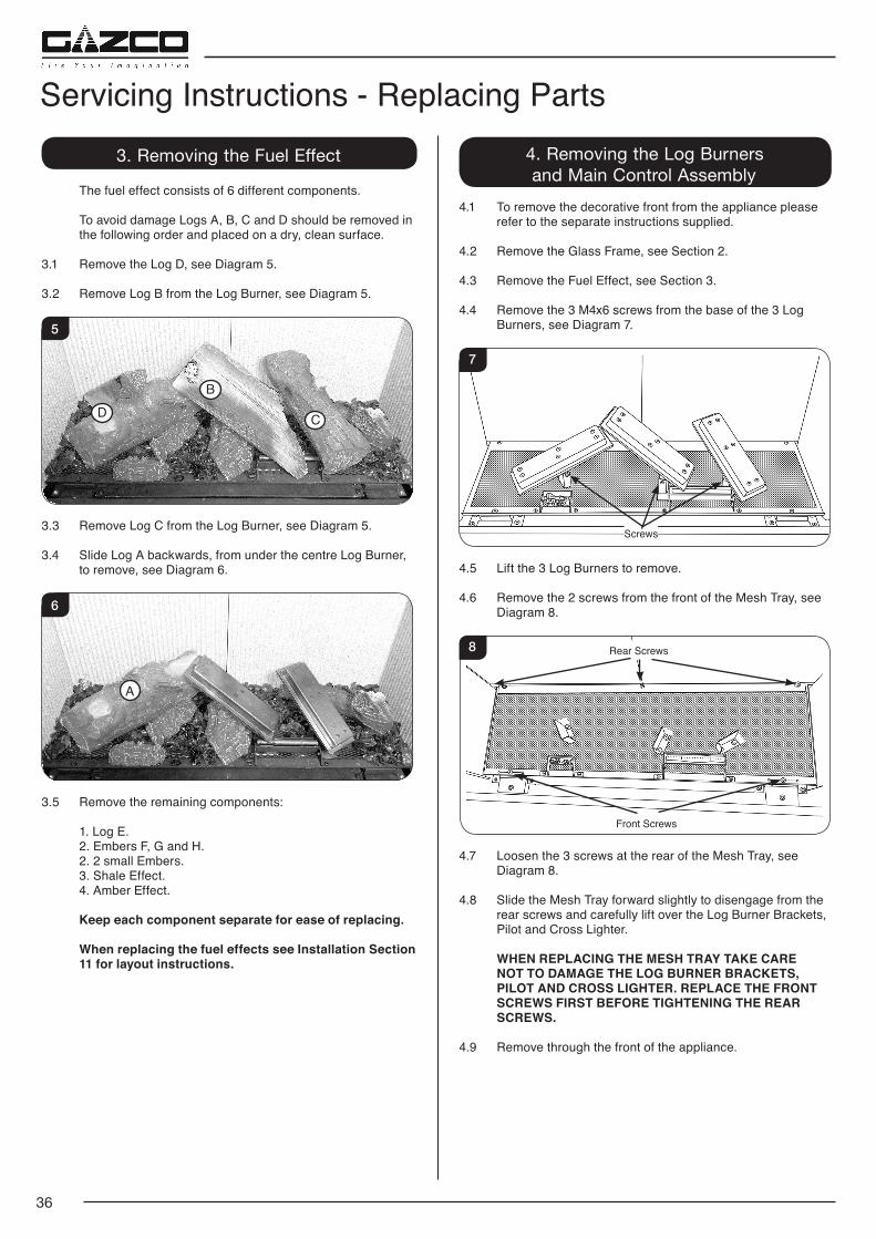
36
3. Removing the Fuel Effect
The fuel effect consists of 6 different components.
To avoid damage Logs A, B, C and D should be removed in the following order and placed on a dry, clean surface.
3.1 Remove the Log D, see Diagram 5.
3.2 Remove Log B from the Log Burner, see Diagram 5.
5
B
CD
3.3 Remove Log C from the Log Burner, see Diagram 5.
3.4 Slide Log A backwards, from under the centre Log Burner, to remove, see Diagram 6.
6
A
3.5 Remove the remaining components: 1. Log E. 2. Embers F, G and H. 2. 2 small Embers. 3. Shale Effect. 4. Amber Effect.
Keep each component separate for ease of replacing.
When replacing the fuel effects see Installation Section 11 for layout instructions.
4. Removing the Log Burners and Main Control Assembly
4.1 To remove the decorative front from the appliance please refer to the separate instructions supplied.
4.2 Remove the Glass Frame, see Section 2.
4.3 Remove the Fuel Effect, see Section 3.
4.4 Remove the 3 M4x6 screws from the base of the 3 Log Burners, see Diagram 7.
7
Screws
4.5 Lift the 3 Log Burners to remove.
4.6 Remove the 2 screws from the front of the Mesh Tray, see Diagram 8.
8 Rear Screws
Front Screws
4.7 Loosen the 3 screws at the rear of the Mesh Tray, see Diagram 8.
4.8 Slide the Mesh Tray forward slightly to disengage from the rear screws and carefully lift over the Log Burner Brackets, Pilot and Cross Lighter.
WHEN REPLACING THE MESH TRAY TAKE CARE NOT TO DAMAGE THE LOG BURNER BRACKETS, PILOT AND CROSS LIGHTER. REPLACE THE FRONT SCREWS FIRST BEFORE TIGHTENING THE REAR SCREWS.
4.9 Remove through the front of the appliance.
Servicing Instructions - Replacing Parts
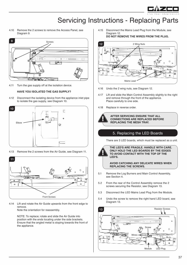
37
4.10 Remove the 2 screws to remove the Access Panel, see Diagram 9.
9 Screws
4.11 Turn the gas supply off at the isolation device.
HAVE YOU ISOLATED THE GAS SUPPLY?
4.12 Disconnect the isolating device from the appliance inlet pipe to isolate the gas supply, see Diagram 10.
10
Elbow
4.13 Remove the 2 screws from the Air Guide, see Diagram 11.
11
Front Screws
4.14 Lift and rotate the Air Guide upwards from the front edge to remove.
Note the orientation for reassembly.
NOTE: To replace; rotate and slide the Air Guide into position with the ends locating under the side brackets.
Ensure that the angled metal is sloping towards the front of the appliance.
4.15 Disconnect the Mains Lead Plug from the Module, see Diagram 12.
DO NOT REMOVE THE WIRES FROM THE PLUG.
12
Mains Lead
2 Wing Nuts
4.16 Undo the 2 wing nuts, see Diagram 12.
4.17 Lift and slide the Main Control Assembly slightly to the right and remove through the front of the appliance.
Place carefully to one side.
4.18 Replace in reverse order.
AFTER SERVICING ENSURE THAT ALL CONNECTIONS ARE REPLACED BEFORE REPLACING THE MESH TRAY.
5. Replacing the LED Boards
There are 3 LED boards, which must be replaced as a unit.
THE LED'S ARE FRAGILE. HANDLE WITH CARE.ONLY HOLD THE LED BOARDS BY THE EDGES TO AVOID CONTACT WITH THE TOP OF THE LED'S.
AVOID CATCHING ANY DELICATE WIRES WHEN REPLACING THE SCREWS.
5.1 Remove the Log Burners and Main Control Assembly, see Section 4.
5.2 From the rear of the Control Assembly remove the 2 screws securing the Resistor, see Diagram 13.
5.3 Disconnect the LED Mains Lead Plug from the Module.
5.4 Undo the screw to remove the right hand LED board, see Diagram 13.
13
Screw
Module LED Plug
Resistor Screws
Wires
Servicing Instructions - Replacing Parts
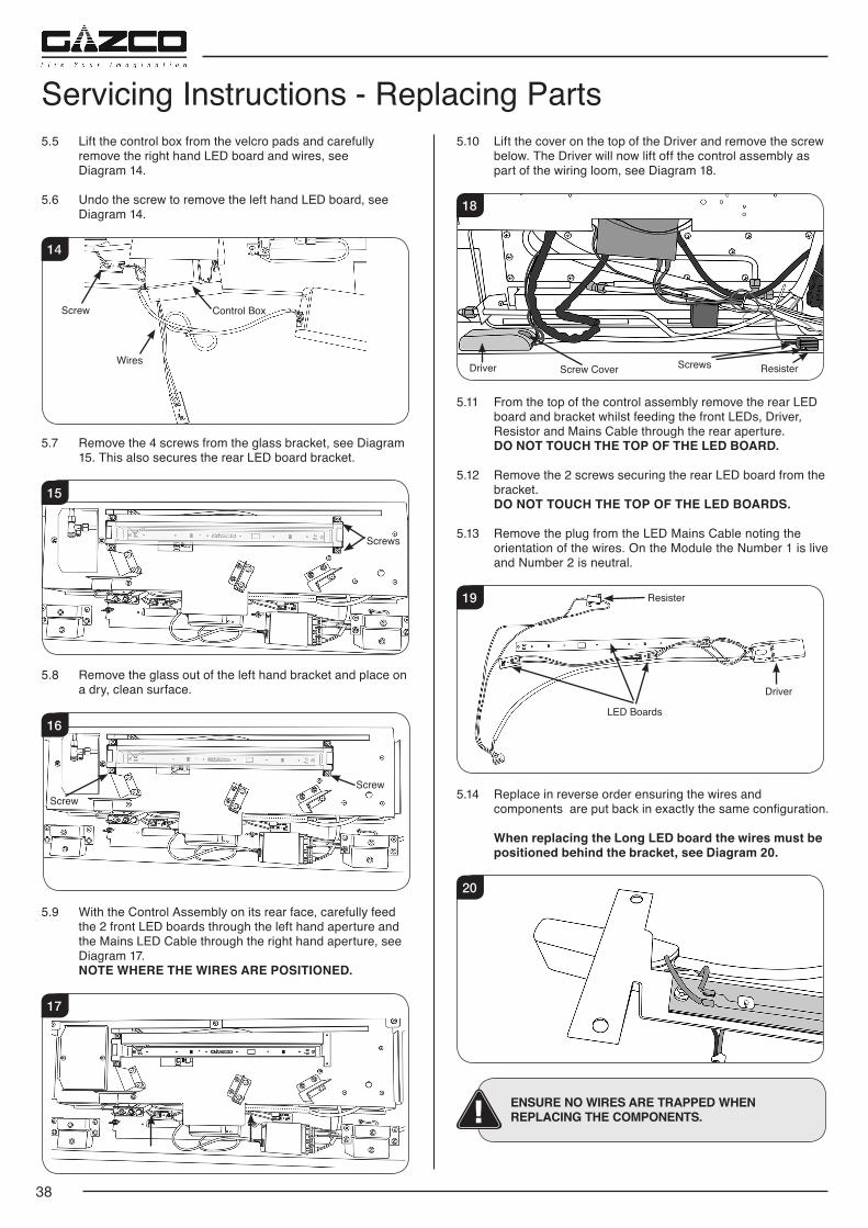
38
Servicing Instructions - Replacing Parts5.5 Lift the control box from the velcro pads and carefully
remove the right hand LED board and wires, see Diagram 14.
5.6 Undo the screw to remove the left hand LED board, see Diagram 14.
14
Screw
Wires
Control Box
5.7 Remove the 4 screws from the glass bracket, see Diagram 15. This also secures the rear LED board bracket.
15
Screws
5.8 Remove the glass out of the left hand bracket and place on a dry, clean surface.
16
ScrewScrew
5.9 With the Control Assembly on its rear face, carefully feed the 2 front LED boards through the left hand aperture and the Mains LED Cable through the right hand aperture, see Diagram 17.
NOTE WHERE THE WIRES ARE POSITIONED.
17
5.10 Lift the cover on the top of the Driver and remove the screw below. The Driver will now lift off the control assembly as part of the wiring loom, see Diagram 18.
18
Screws ResisterDriver Screw Cover
5.11 From the top of the control assembly remove the rear LED board and bracket whilst feeding the front LEDs, Driver, Resistor and Mains Cable through the rear aperture. DO NOT TOUCH THE TOP OF THE LED BOARD.
5.12 Remove the 2 screws securing the rear LED board from the bracket.
DO NOT TOUCH THE TOP OF THE LED BOARDS.
5.13 Remove the plug from the LED Mains Cable noting the orientation of the wires. On the Module the Number 1 is live and Number 2 is neutral.
19 Resister
LED Boards
Driver
5.14 Replace in reverse order ensuring the wires and components are put back in exactly the same configuration.
When replacing the Long LED board the wires must be positioned behind the bracket, see Diagram 20.
20
ENSURE NO WIRES ARE TRAPPED WHEN REPLACING THE COMPONENTS.
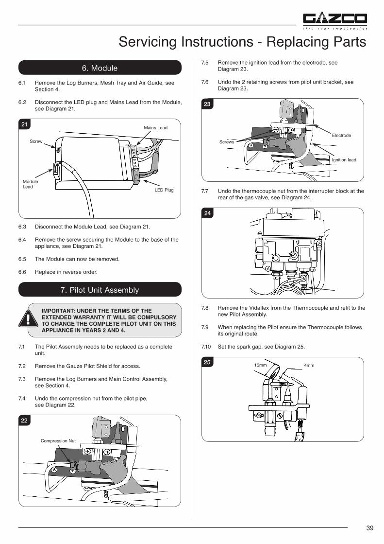
39
Servicing Instructions - Replacing Parts6. Module
6.1 Remove the Log Burners, Mesh Tray and Air Guide, see Section 4.
6.2 Disconnect the LED plug and Mains Lead from the Module, see Diagram 21.
21 Mains Lead
Module Lead
Screw
LED Plug
6.3 Disconnect the Module Lead, see Diagram 21.
6.4 Remove the screw securing the Module to the base of the appliance, see Diagram 21.
6.5 The Module can now be removed.
6.6 Replace in reverse order.
7. Pilot Unit Assembly
IMPORTANT: UNDER THE TERMS OF THE EXTENDED WARRANTY IT WILL BE COMPULSORY TO CHANGE THE COMPLETE PILOT UNIT ON THIS APPLIANCE IN YEARS 2 AND 4.
7.1 The Pilot Assembly needs to be replaced as a complete unit.
7.2 Remove the Gauze Pilot Shield for access.
7.3 Remove the Log Burners and Main Control Assembly, see Section 4.
7.4 Undo the compression nut from the pilot pipe, see Diagram 22.
22
Compression Nut
7.5 Remove the ignition lead from the electrode, see Diagram 23.
7.6 Undo the 2 retaining screws from pilot unit bracket, see Diagram 23.
23
Ignition lead
ElectrodeScrews
7.7 Undo the thermocouple nut from the interrupter block at the rear of the gas valve, see Diagram 24.
24
7.8 Remove the Vidaflex from the Thermocouple and refit to the new Pilot Assembly.
7.9 When replacing the Pilot ensure the Thermocouple follows its original route.
7.10 Set the spark gap, see Diagram 25.
25 15mm 4mm
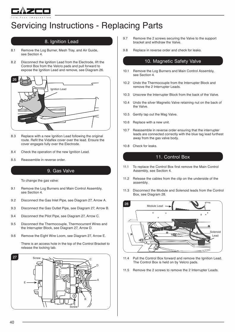
40
Servicing Instructions - Replacing Parts8. Ignition Lead
8.1 Remove the Log Burner, Mesh Tray, and Air Guide, see Section 4.
8.2 Disconnect the Ignition Lead from the Electrode, lift the Control Box from the Velcro pads and pull forward to expose the Ignition Lead and remove, see Diagram 26.
26
Ignition Lead
8.3 Replace with a new Ignition Lead following the original route. Refit the Vidaflex cover over the lead. Ensure the cover engages fully over the Electrode.
8.4 Check the operation of the new Ignition Lead.
8.5 Reassemble in reverse order.
9. Gas Valve
To change the gas valve:
9.1 Remove the Log Burners and Main Control Assembly, see Section 4.
9.2 Disconnect the Gas Inlet Pipe, see Diagram 27, Arrow A.
9.3 Disconnect the Gas Outlet Pipe, see Diagram 27, Arrow B.
9.4 Disconnect the Pilot Pipe, see Diagram 27, Arrow C.
9.5 Disconnect the Thermocouple, Thermocurrent Wires and the Interrupter Block, see Diagram 27, Arrow D.
9.6 Remove the Eight Wire Loom, see Diagram 27, Arrow E.
There is an access hole in the top of the Control Bracket to release the locking tab.
C
D
A
B
E
27
Screw
Screw
9.7 Remove the 2 screws securing the Valve to the support bracket and withdraw the Valve.
9.8 Replace in reverse order and check for leaks.
10. Magnetic Safety Valve
10.1 Remove the Log Burners and Main Control Assembly, see Section 4.
10.2 Undo the Thermocouple from the Interrupter Block and remove the 2 Interrupter Leads.
10.3 Unscrew the Interrupter Block from the back of the Valve.
10.4 Undo the silver Magnetic Valve retaining nut on the back of the Valve.
10.5 Gently tap out the Mag Valve.
10.6 Replace with a new unit.
10.7 Reassemble in reverse order ensuring that the interrupter leads are connected correctly with the blue tag lead furthest away from the gas valve body.
10.8 Check for leaks.
11. Control Box
11.1 To replace the Control Box first remove the Main Control Assembly, see Section 4.
11.2 Release the cables from the clip on the underside of the assembly.
11.3 Disconnect the Module and Solenoid leads from the Control Box, see Diagram 28.
28 Module Lead
Solenoid Lead
11.4 Pull the Control Box forward and remove the Ignition Lead. The Control Box is held on by Velcro pads.
11.5 Remove the 2 screws to remove the 2 Interrupter Leads.
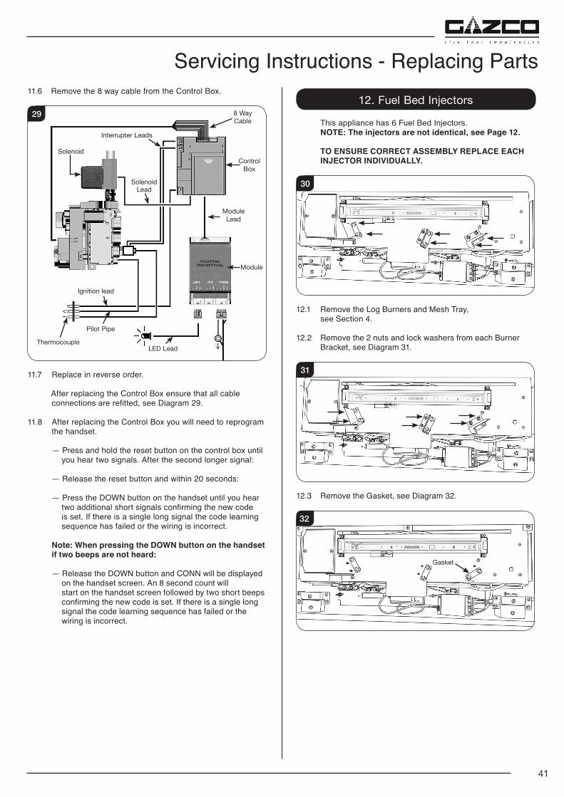
41
Servicing Instructions - Replacing Parts11.6 Remove the 8 way cable from the Control Box.
8 Way Cable
Interrupter Leads
Ignition lead
LED Lead
29
Module Lead
Solenoid Lead
Thermocouple
Pilot Pipe
Control Box
Module
Solenoid
11.7 Replace in reverse order.
After replacing the Control Box ensure that all cable connections are refitted, see Diagram 29.
11.8 After replacing the Control Box you will need to reprogram the handset.
— Press and hold the reset button on the control box until you hear two signals. After the second longer signal:
— Release the reset button and within 20 seconds:
— Press the DOWN button on the handset until you hear two additional short signals confirming the new code
is set. If there is a single long signal the code learning sequence has failed or the wiring is incorrect.
Note: When pressing the DOWN button on the handset if two beeps are not heard:
— Release the DOWN button and CONN will be displayed on the handset screen. An 8 second count will start on the handset screen followed by two short beeps confirming the new code is set. If there is a single long signal the code learning sequence has failed or the wiring is incorrect.
12. Fuel Bed Injectors
This appliance has 6 Fuel Bed Injectors. NOTE: The injectors are not identical, see Page 12.
TO ENSURE CORRECT ASSEMBLY REPLACE EACH INJECTOR INDIVIDUALLY.
30
12.1 Remove the Log Burners and Mesh Tray, see Section 4.
12.2 Remove the 2 nuts and lock washers from each Burner Bracket, see Diagram 31.
31
12.3 Remove the Gasket, see Diagram 32.
32
Gasket
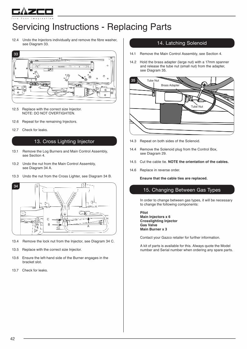
42
12.4 Undo the Injectors individually and remove the fibre washer, see Diagram 33.
33
12.5 Replace with the correct size Injector. NOTE: DO NOT OVERTIGHTEN.
12.6 Repeat for the remaining Injectors.
12.7 Check for leaks.
13. Cross Lighting Injector
13.1 Remove the Log Burners and Main Control Assembly, see Section 4.
13.2 Undo the nut from the Main Control Assembly, see Diagram 34 A.
13.3 Undo the nut from the Cross Lighter, see Diagram 34 B.
34
B
C
A
13.4 Remove the lock nut from the Injector, see Diagram 34 C.
13.5 Replace with the correct size Injector.
13.6 Ensure the left-hand side of the Burner engages in the bracket slot.
13.7 Check for leaks.
Servicing Instructions - Replacing Parts14. Latching Solenoid
14.1 Remove the Main Control Assembly, see Section 4.
14.2 Hold the brass adapter (large nut) with a 17mm spanner and release the tube nut (small nut) from the adapter, see Diagram 35.
35Brass Adapter
Tube Nut
Tube Nut
14.3 Repeat on both sides of the Solenoid.
14.4 Remove the Solenoid plug from the Control Box, see Diagram 29.
14.5 Cut the cable tie. NOTE the orientation of the cables.
14.6 Replace in reverse order.
Ensure that the cable ties are replaced.
15. Changing Between Gas Types
In order to change between gas types, it will be necessary to change the following components:
Pilot Main Injectors x 6 Crosslighting Injector Gas Valve Main Burner x 3
Contact your Gazco retailer for further information.
A kit of parts is available for this. Always quote the Model number and Serial number when ordering any spare parts.
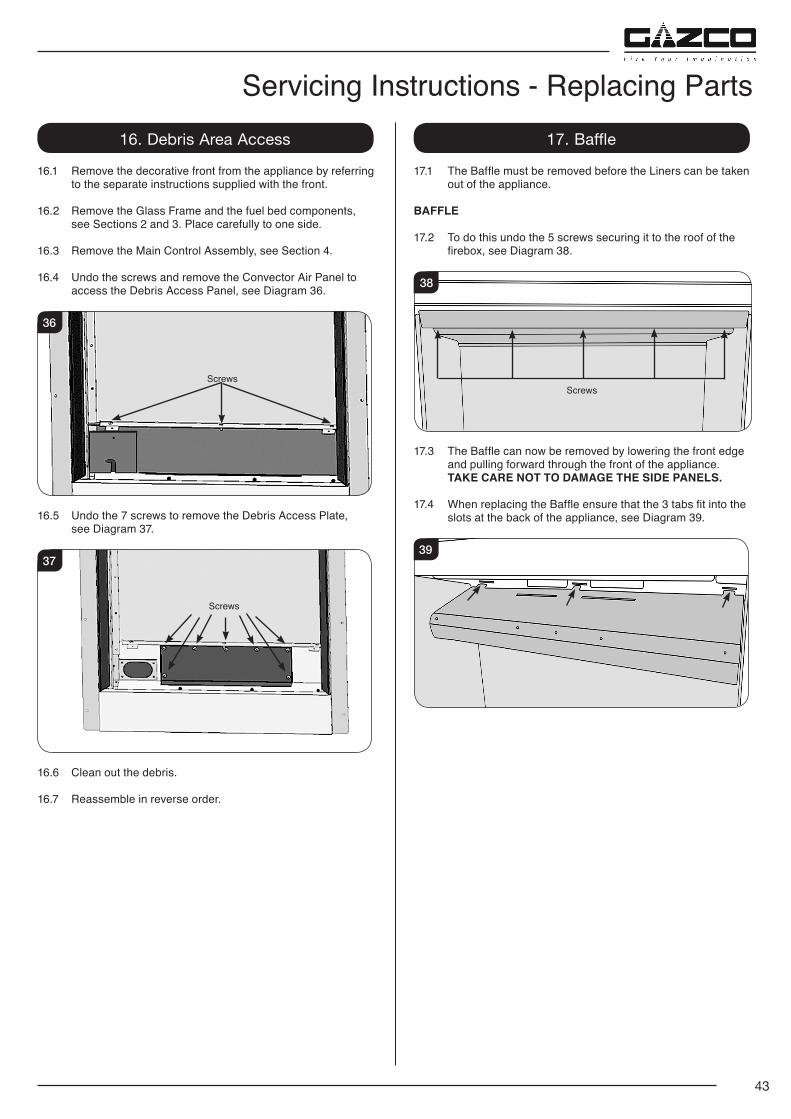
43
Servicing Instructions - Replacing Parts16. Debris Area Access
16.1 Remove the decorative front from the appliance by referring to the separate instructions supplied with the front.
16.2 Remove the Glass Frame and the fuel bed components, see Sections 2 and 3. Place carefully to one side.
16.3 Remove the Main Control Assembly, see Section 4.
16.4 Undo the screws and remove the Convector Air Panel to access the Debris Access Panel, see Diagram 36.
36
Screws
16.5 Undo the 7 screws to remove the Debris Access Plate, see Diagram 37.
37
Screws
16.6 Clean out the debris.
16.7 Reassemble in reverse order.
17. Baffle
17.1 The Baffle must be removed before the Liners can be taken out of the appliance.
BAFFLE
17.2 To do this undo the 5 screws securing it to the roof of the firebox, see Diagram 38.
Screws
38
17.3 The Baffle can now be removed by lowering the front edge and pulling forward through the front of the appliance.
TAKE CARE NOT TO DAMAGE THE SIDE PANELS.
17.4 When replacing the Baffle ensure that the 3 tabs fit into the slots at the back of the appliance, see Diagram 39.
39
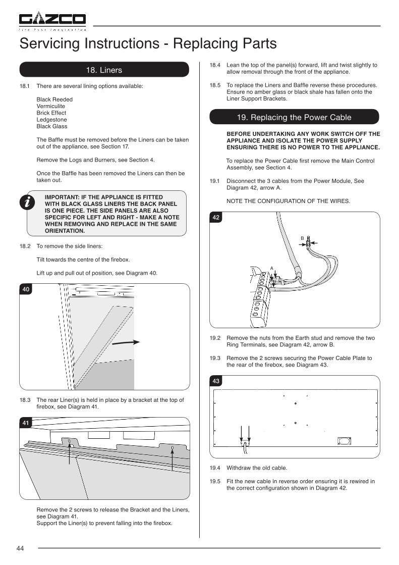
44
18. Liners
18.1 There are several lining options available:
Black Reeded Vermiculite Brick Effect Ledgestone Black Glass The Baffle must be removed before the Liners can be taken
out of the appliance, see Section 17.
Remove the Logs and Burners, see Section 4.
Once the Baffle has been removed the Liners can then be taken out.
IMPORTANT: IF THE APPLIANCE IS FITTED WITH BLACK GLASS LINERS THE BACK PANEL IS ONE PIECE. THE SIDE PANELS ARE ALSO SPECIFIC FOR LEFT AND RIGHT - MAKE A NOTE WHEN REMOVING AND REPLACE IN THE SAME ORIENTATION.
18.2 To remove the side liners:
Tilt towards the centre of the firebox.
Lift up and pull out of position, see Diagram 40.
40
18.3 The rear Liner(s) is held in place by a bracket at the top of firebox, see Diagram 41.
41
Remove the 2 screws to release the Bracket and the Liners, see Diagram 41.
Support the Liner(s) to prevent falling into the firebox.
18.4 Lean the top of the panel(s) forward, lift and twist slightly to allow removal through the front of the appliance.
18.5 To replace the Liners and Baffle reverse these procedures. Ensure no amber glass or black shale has fallen onto the Liner Support Brackets.
19. Replacing the Power Cable
BEFORE UNDERTAKING ANY WORK SWITCH OFF THE APPLIANCE AND ISOLATE THE POWER SUPPLY ENSURING THERE IS NO POWER TO THE APPLIANCE.
To replace the Power Cable first remove the Main Control Assembly, see Section 4.
19.1 Disconnect the 3 cables from the Power Module, See Diagram 42, arrow A.
NOTE THE CONFIGURATION OF THE WIRES.
42
A
B
19.2 Remove the nuts from the Earth stud and remove the two Ring Terminals, see Diagram 42, arrow B.
19.3 Remove the 2 screws securing the Power Cable Plate to the rear of the firebox, see Diagram 43.
43
19.4 Withdraw the old cable.
19.5 Fit the new cable in reverse order ensuring it is rewired in the correct configuration shown in Diagram 42.
Servicing Instructions - Replacing Parts
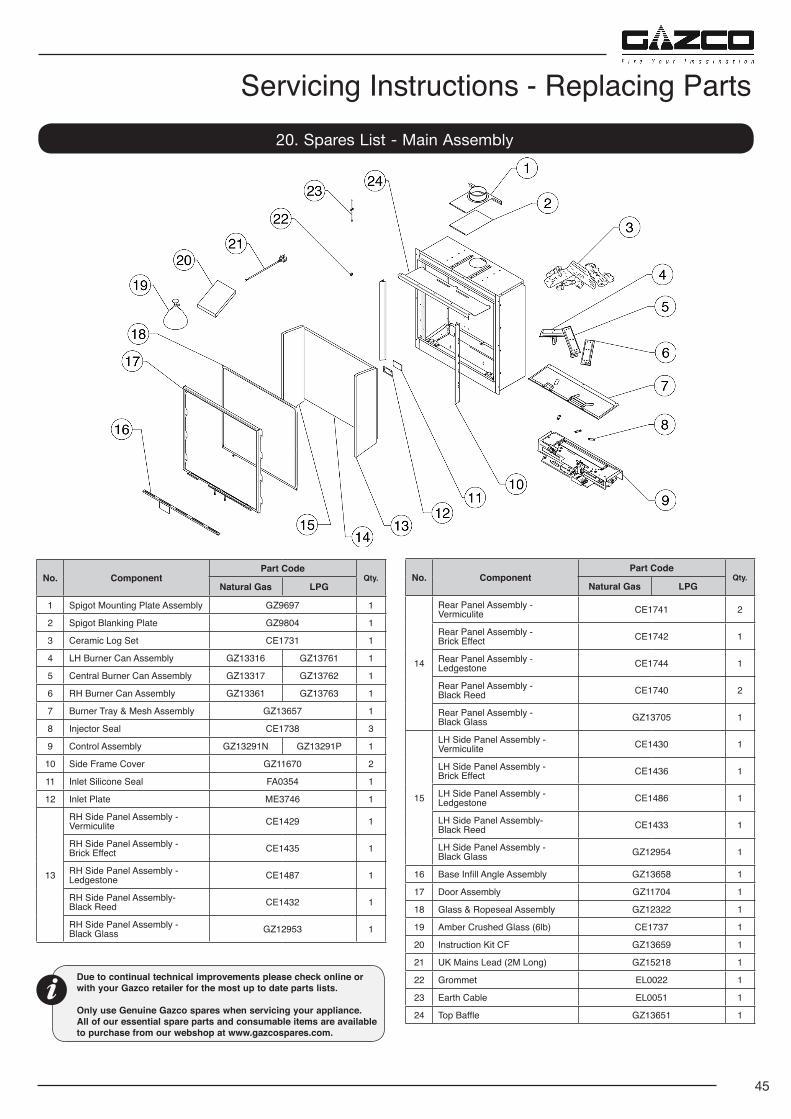
45
Servicing Instructions - Replacing Parts20. Spares List - Main Assembly
No. ComponentPart Code
Qty.Natural Gas LPG
1 Spigot Mounting Plate Assembly GZ9697 1
2 Spigot Blanking Plate GZ9804 1
3 Ceramic Log Set CE1731 1
4 LH Burner Can Assembly GZ13316 GZ13761 1
5 Central Burner Can Assembly GZ13317 GZ13762 1
6 RH Burner Can Assembly GZ13361 GZ13763 1
7 Burner Tray & Mesh Assembly GZ13657 1
8 Injector Seal CE1738 3
9 Control Assembly GZ13291N GZ13291P 1
10 Side Frame Cover GZ11670 2
11 Inlet Silicone Seal FA0354 1
12 Inlet Plate ME3746 1
13
RH Side Panel Assembly - Vermiculite CE1429 1
RH Side Panel Assembly - Brick Effect CE1435 1
RH Side Panel Assembly - Ledgestone CE1487 1
RH Side Panel Assembly-Black Reed CE1432 1
RH Side Panel Assembly - Black Glass GZ12953 1
No. ComponentPart Code
Qty.Natural Gas LPG
14
Rear Panel Assembly - Vermiculite CE1741 2
Rear Panel Assembly - Brick Effect CE1742 1
Rear Panel Assembly - Ledgestone CE1744 1
Rear Panel Assembly -Black Reed CE1740 2
Rear Panel Assembly - Black Glass GZ13705 1
15
LH Side Panel Assembly - Vermiculite CE1430 1
LH Side Panel Assembly - Brick Effect CE1436 1
LH Side Panel Assembly - Ledgestone CE1486 1
LH Side Panel Assembly-Black Reed CE1433 1
LH Side Panel Assembly - Black Glass GZ12954 1
16 Base Infill Angle Assembly GZ13658 1
17 Door Assembly GZ11704 1
18 Glass & Ropeseal Assembly GZ12322 1
19 Amber Crushed Glass (6lb) CE1737 1
20 Instruction Kit CF GZ13659 1
21 UK Mains Lead (2M Long) GZ15218 1
22 Grommet EL0022 1
23 Earth Cable EL0051 1
24 Top Baffle GZ13651 1
Due to continual technical improvements please check online or with your Gazco retailer for the most up to date parts lists.
Only use Genuine Gazco spares when servicing your appliance. All of our essential spare parts and consumable items are available to purchase from our webshop at www.gazcospares.com.
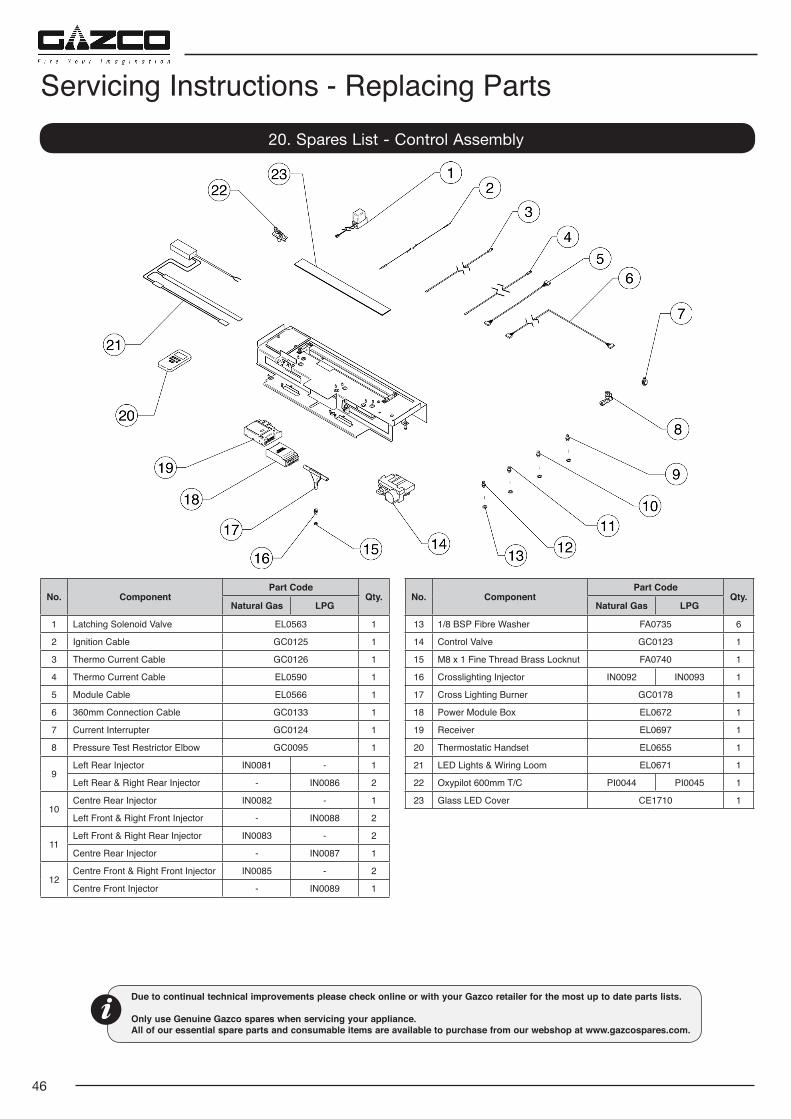
46
Servicing Instructions - Replacing Parts
No. ComponentPart Code
Qty.Natural Gas LPG
1 Latching Solenoid Valve EL0563 1
2 Ignition Cable GC0125 1
3 Thermo Current Cable GC0126 1
4 Thermo Current Cable EL0590 1
5 Module Cable EL0566 1
6 360mm Connection Cable GC0133 1
7 Current Interrupter GC0124 1
8 Pressure Test Restrictor Elbow GC0095 1
9Left Rear Injector IN0081 - 1
Left Rear & Right Rear Injector - IN0086 2
10Centre Rear Injector IN0082 - 1
Left Front & Right Front Injector - IN0088 2
11Left Front & Right Rear Injector IN0083 - 2
Centre Rear Injector - IN0087 1
12Centre Front & Right Front Injector IN0085 - 2
Centre Front Injector - IN0089 1
20. Spares List - Control Assembly
No. ComponentPart Code
Qty.Natural Gas LPG
13 1/8 BSP Fibre Washer FA0735 6
14 Control Valve GC0123 1
15 M8 x 1 Fine Thread Brass Locknut FA0740 1
16 Crosslighting Injector IN0092 IN0093 1
17 Cross Lighting Burner GC0178 1
18 Power Module Box EL0672 1
19 Receiver EL0697 1
20 Thermostatic Handset EL0655 1
21 LED Lights & Wiring Loom EL0671 1
22 Oxypilot 600mm T/C PI0044 PI0045 1
23 Glass LED Cover CE1710 1
Due to continual technical improvements please check online or with your Gazco retailer for the most up to date parts lists.
Only use Genuine Gazco spares when servicing your appliance. All of our essential spare parts and consumable items are available to purchase from our webshop at www.gazcospares.com.
47
Service Records
1ST SERVICE
Date of Service:..........................................................................
Next Service Due:......................................................................
Signed:.......................................................................................
Retailer's Stamp/GasSafe Registration Number
3RD SERVICE
Date of Service:..........................................................................
Next Service Due:......................................................................
Signed:.......................................................................................
Retailer's Stamp/GasSafe Registration Number
5TH SERVICE
Date of Service:..........................................................................
Next Service Due:......................................................................
Signed:.......................................................................................
Retailer's Stamp/GasSafe Registration Number
7TH SERVICE
Date of Service:..........................................................................
Next Service Due:......................................................................
Signed:.......................................................................................
Retailer's Stamp/GasSafe Registration Number
9TH SERVICE
Date of Service:..........................................................................
Next Service Due:......................................................................
Signed:.......................................................................................
Retailer's Stamp/GasSafe Registration Number
2ND SERVICE
Date of Service:..........................................................................
Next Service Due:......................................................................
Signed:.......................................................................................
Retailer's Stamp/GasSafe Registration Number
4TH SERVICE
Date of Service:..........................................................................
Next Service Due:......................................................................
Signed:.......................................................................................
Retailer's Stamp/GasSafe Registration Number
6TH SERVICE
Date of Service:..........................................................................
Next Service Due:......................................................................
Signed:.......................................................................................
Retailer's Stamp/GasSafe Registration Number
8TH SERVICE
Date of Service:..........................................................................
Next Service Due:......................................................................
Signed:.......................................................................................
Retailer's Stamp/GasSafe Registration Number
10TH SERVICE
Date of Service:..........................................................................
Next Service Due:......................................................................
Signed:.......................................................................................
Retailer's Stamp/GasSafe Registration Number
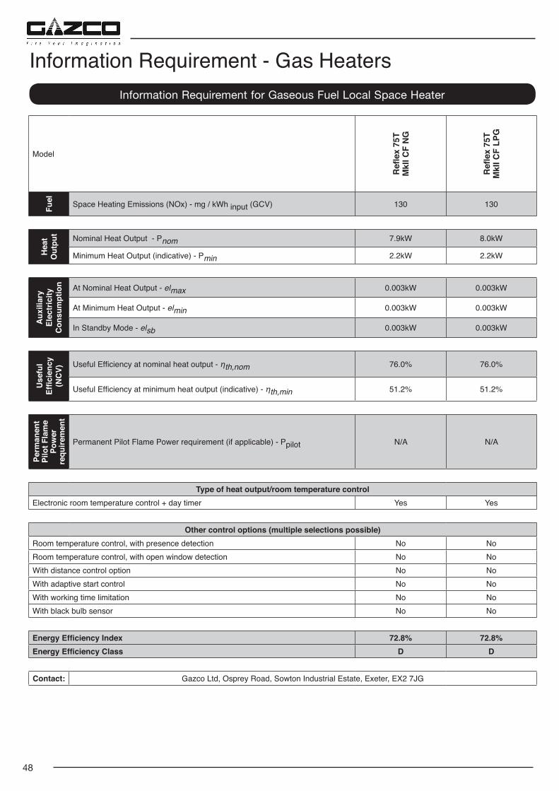
48
Model
Refl
ex 7
5TM
kII C
F N
G
Refl
ex 7
5TM
kII C
F LP
G
Fuel Space Heating Emissions (NOx) - mg / kWh input (GCV) 130 130
Hea
tO
utpu
t Nominal Heat Output - Pnom 7.9kW 8.0kW
Minimum Heat Output (indicative) - Pmin 2.2kW 2.2kW
Aux
iliar
y El
ectr
icity
C
onsu
mpt
ion At Nominal Heat Output - elmax 0.003kW 0.003kW
At Minimum Heat Output - elmin 0.003kW 0.003kW
In Standby Mode - elsb 0.003kW 0.003kW
Use
ful
Effic
ienc
y (N
CV)
Useful Efficiency at nominal heat output - ηth,nom 76.0% 76.0%
Useful Efficiency at minimum heat output (indicative) - ηth,min 51.2% 51.2%
Perm
anen
t Pi
lot F
lam
e Po
wer
re
quire
men
t
Permanent Pilot Flame Power requirement (if applicable) - Ppilot N/A N/A
Type of heat output/room temperature controlElectronic room temperature control + day timer Yes Yes
Other control options (multiple selections possible)Room temperature control, with presence detection No NoRoom temperature control, with open window detection No NoWith distance control option No NoWith adaptive start control No NoWith working time limitation No NoWith black bulb sensor No No
Energy Efficiency Index 72.8% 72.8%Energy Efficiency Class D D
Contact: Gazco Ltd, Osprey Road, Sowton Industrial Estate, Exeter, EX2 7JG
Information Requirement for Gaseous Fuel Local Space Heater
Information Requirement - Gas Heaters


Gazco Limited, Osprey Road, Sowton Industrial Estate, Exeter, Devon, England EX2 7JGTechnical Customer Services: (01392) 261950 Fax: (01392) 261951
E-mail: [email protected] member of the Stovax Group
E & O E