Embed Size (px)
Citation preview
1
Students’ understanding of direct current resistive electrical circuits
by Paula Vetter Engelhardt and Robert J. Beichner
Department of Physics, North Carolina State University, Raleigh, North Carolina 27695
Abstract
Both high school and university students’ reasoning regarding direct
current resistive electric circuits often differ from the accepted explanations. At
present, there are no standard diagnostic tests on electric circuits. Two versions
of a diagnostic instrument were developed, each consisting of 29 questions. The
information provided by this test can provide instructors with a way of
evaluating the progress and conceptual difficulties of their students. The analysis
indicates that students, especially females, tend to hold multiple misconceptions,
even after instruction. During interviews, the idea that the battery is a constant
source of current was used most often in answering the questions. Students
tended to focus on the current in solving problems and to confuse terms, often
assigning the properties of current to voltage and/or resistance.
2
I. Introduction
In recent years, physics educators have begun to look more closely at
what their students understand about physics concepts. Students’ patterns of
response to questions about circuit phenomena often are in conflict with those
accepted by the physics community. The term “misconception” will be used to
refer to students’ incorrect pattern of response. This pattern could be part of a
coherent naive theory of some physical phenomena or a more fragmented and
primitive response produced on the spot as a result of the questions posed.
Widespread use of test instruments such as the Force Concept Inventory
(FCI)1 and the Test of Understanding Graphs in Kinematics (TUG-K)2 has
brought a new way of evaluating students’ conceptual understanding. However,
more instruments need to be developed in a variety of areas to allow instructors
to better evaluate their students’ understanding of physics concepts and to
evaluate new teaching endeavours for their feasibility. The Determining and
Interpreting Resistive Electric Circuit Concepts Test (DIRECT) was developed to
evaluate students’ understanding of a variety of direct current (DC) resistive
electric circuits concepts. DIRECT has been designed for use with high school
and college/university students. Common misconceptions were incorporated
into the distracters of the test items.
We will discuss the development of DIRECT versions 1.0 and 1.1 and will
examine their feasibility for assessing students’ conceptual understanding and
3
potential use in evaluating curricula. We will answer the following research
questions: (1) Can a multiple-choice test be developed that is reliable, valid, and
uncovers students’ misconceptions? (2) Are there significant differences between
various groups of students taking DIRECT? In particular, are there noticeable
differences between course level (high school versus university), gender, and
instructional methods? (3) What misconceptions can the test detect?
The body of knowledge regarding students’ understanding of DC
resistive electric circuits is quite extensive.3 Students’ typical response patterns
indicate that they make two assumptions regarding DC resistive electrical
circuits: current is consumed,4 and the battery is a source of constant current.5 In
addition, students interchangeably use terms associated with circuits, often
assigning the properties of current either to voltage, resistance, energy, or
power.6
Physicists use schematic diagrams to represent circuit elements and
examine their behavior. Students’ recognition of what these diagrams represent
is an important aspect of their understanding of circuits. Research reveals that
students view these diagrams as a system of pipes within which flows a fluid
that they refer to as electricity.7 Students have difficulty identifying series and
parallel connections in diagrams.8 Students do not understand and do not
correctly apply the concept of a complete circuit.9 Gott10 has reported that more
than 90% of students age 15 recognized the need for a complete circuit. However,
4
he found a small but significant group of students who would include a short
circuit (such as a shorted battery) as an acceptable complete circuit.
In analyzing circuits, students view it in a piece-meal fashion in contrast to
a global view. There is some evidence11 to indicate that students change their
reasoning patterns to suit the question at hand. Thus, they do not appear to use a
single, consistent model to analyze circuit phenomena. Instead, students use one
of three ways of reasoning: sequential, local, or superposition. Sequential
reasoning results in a “before and after” examination of the circuit. Students
using sequential reasoning believe that current travels around the circuit and is
influenced by each element as it is encountered, and a change made at a
particular point does not affect the current until it reaches that point.12 Thus, for
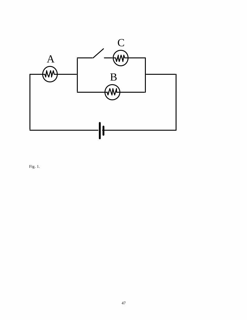
the circuit shown in Fig. 1, closing the switch will not affect bulb A because the
current has already passed that point. Von Rhöneck and Grob differentiate local
from sequential reasoning in the following way: “local reasoning means that the
current divides into two equal parts at every junction regardless of what is
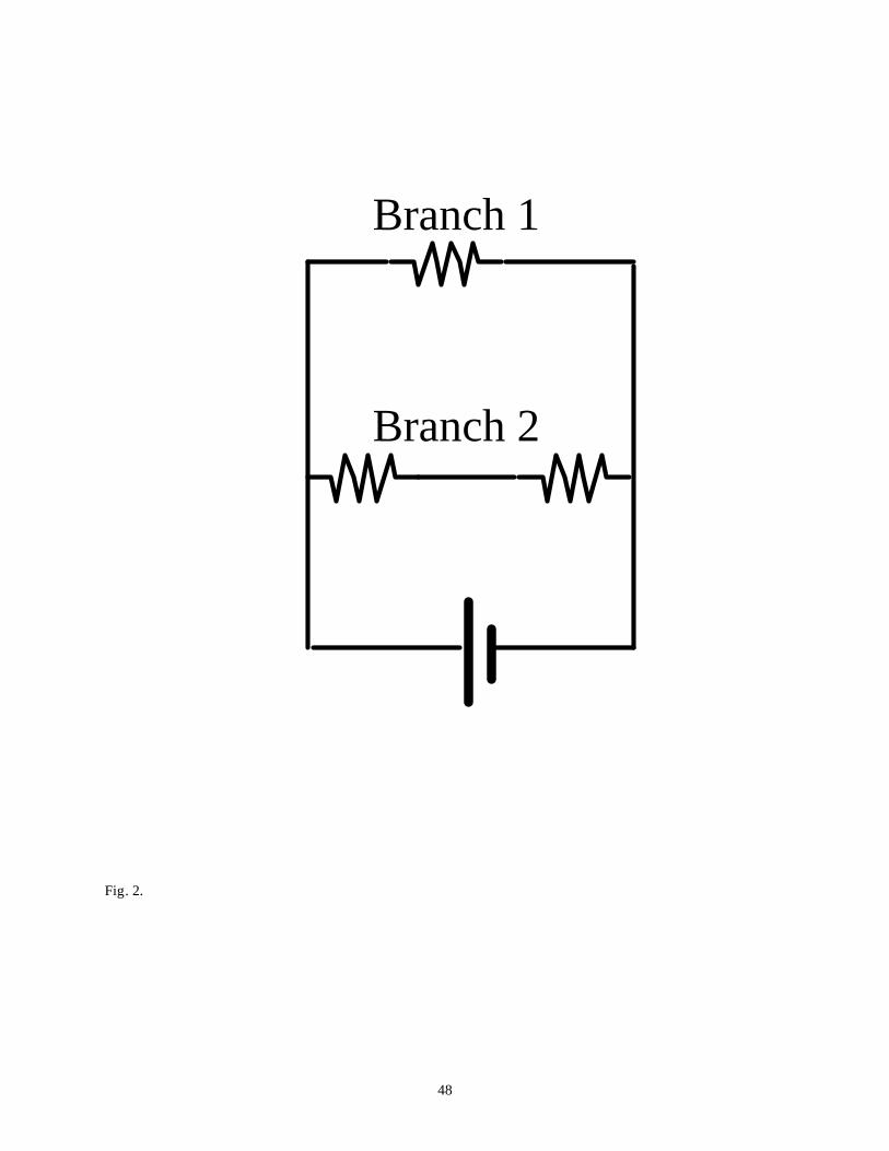
happening elsewhere.”13 Given the circuit shown in Fig. 2, students would say
that the current in branch 1 was equal to that in branch 2. Students using
superposition reasoning would conclude that if one battery makes a bulb shine
with a certain brightness, then two batteries would make the bulb shine twice as
bright, regardless of the configuration.14
5
When confronted with a qualitative problem, students show reluctance
when asked to reason qualitatively and resort to technical or quantitative
approaches.15 This reluctance is said to be due to a lack of experience solving
qualitative problems.16 Additionally, students have been shown to have
difficulty mastering reasoning with ratios.17
Tests on DC resistive electric circuits do exist,18 but they have mostly been
developed as either a research tool or curriculum assessment instrument, not as a
general assessment tool. Thus, there are limitations with many of these tests that
prevent them from being used for this purpose. Those that have been developed
as a research tool often have restricted content, looking at a single concept such
as resistance.19 Those that do cover more topics generally have a single item for
each objective,20 which does not allow for comparisons between questions nor
provide additional statistical evidence of comprehension. (Was it the question or
the concept that students didn’t understand?) Statistical evidence pertaining to
the reliability and validity of the tests has not been well documented. Many of
the assessment tests were developed mainly to evaluate and to revise the
curriculum materials with which they were associated. Although some of these
tests reveal and quantify students’ conceptual understanding,21 they usually
were not intended to be used in a wider format. Many of these tests have been
administered to small groups of students with similar abilities or only to the
groups under investigation. Small sample sizes can increase the sampling error.
6
Thus, a test that could be used as both a research tool in assessing new
curriculum materials or teaching strategies as well as evaluating students’
conceptual views that has sound statistical evidence of its reliability and validity
is needed for DC resistive circuits.
II. Development of DIRECT versions 1.0 and 1.1
As a first step in developing DIRECT, a set of instructional objectives was
constructed after an extensive examination of high school and university
textbooks and laboratory manuals plus informal discussions with instructors
using those materials. The objectives were presented to a panel of independent
experts to ensure that no fundamental concepts were overlooked. The final
objectives are shown in Table I.
One typical comment that the panel made regarding the objectives was
the omission of the use of meters in terms of their placement in circuits and their
use as a measurement device to determine the behavior of the circuit. Although
an important part of laboratory work, meters serve as an application of electric
circuits concepts in contrast to a distinct concept of their own. Research has
shown that students fail to treat meters as circuit elements and to recognise the
implications for their construction and external connections.22 Psillos, Koumaras,
and Valassiades23 found that a group of 14-15 year old Greek students believed
that an ammeter would consume current so that it functioned in the same
7
manner as a light bulb. The students did not understand that a good ammeter
simply allows current to flow through it and has a negligible effect on the circuit.
Thus, if such devices were included in the test, it would be difficult to determine
if students were having difficulties with circuit concepts like current, or if they
were having difficulties with the use and function of the meters.
The test was developed first in an open-ended format so that distracters
for the multiple-choice version could be constructed. Efforts were made to write
several items per objective. For example, three questions using a different mode
of representation were written for objective 5. The three modes were verbal to
schematic, realistic to schematic, and schematic to realistic. Some test items were
adapted from the Physics by Inquiry24 materials and College Physics25 by Serway
and Faughn. Members of the independent panel of experts suggested some
items; however, most of the items were original.
In general, the questions were not aligned with any particular
instructional approach so that the results would be the applicable to the largest
possible audience. Questions written for objective 9, microscopic aspects of
circuits, were the only exception and were closely aligned with the approach
proposed by Chabay and Sherwood in their text, Electric and Magnetic
Interactions.26 They were included to evaluate how well students understand the
microscopic aspects of circuits as this connection has only recently begun to be
explored in some of the newer textbooks. As Cohen, Eylon and Ganiel27 have
8
noted, this lack of a causal relation may be the cause of some of the problems
students have with electric circuits.
Large sample sizes were desired to reduce the magnitude of sampling
error.28 Thus, test sites were solicited via a message placed on a listserv for
physics education researchers and educators (PHYS-LRNR) requesting test sites
for the multiple-choice versions of the instrument and via contacts made during
the 1993 Physics Courseware Evaluation Project’s (PCEP) Summer Teachers’
Institute held at North Carolina State University.
The multiple-choice version 1.0 of DIRECT (given in Appendix A) was
administered to 1135 students from high schools (N = 454) and universities
(N = 681) across the United States. The 29-item test took approximately half an
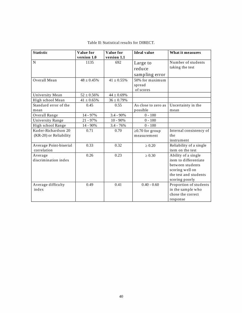
hour to complete. The statistical analysis of the test is presented in Table II along
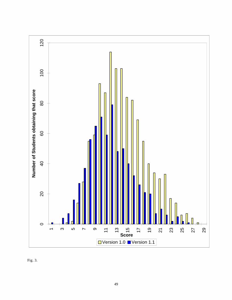
with information about the statistics and their ideal values. Figure 3 shows the
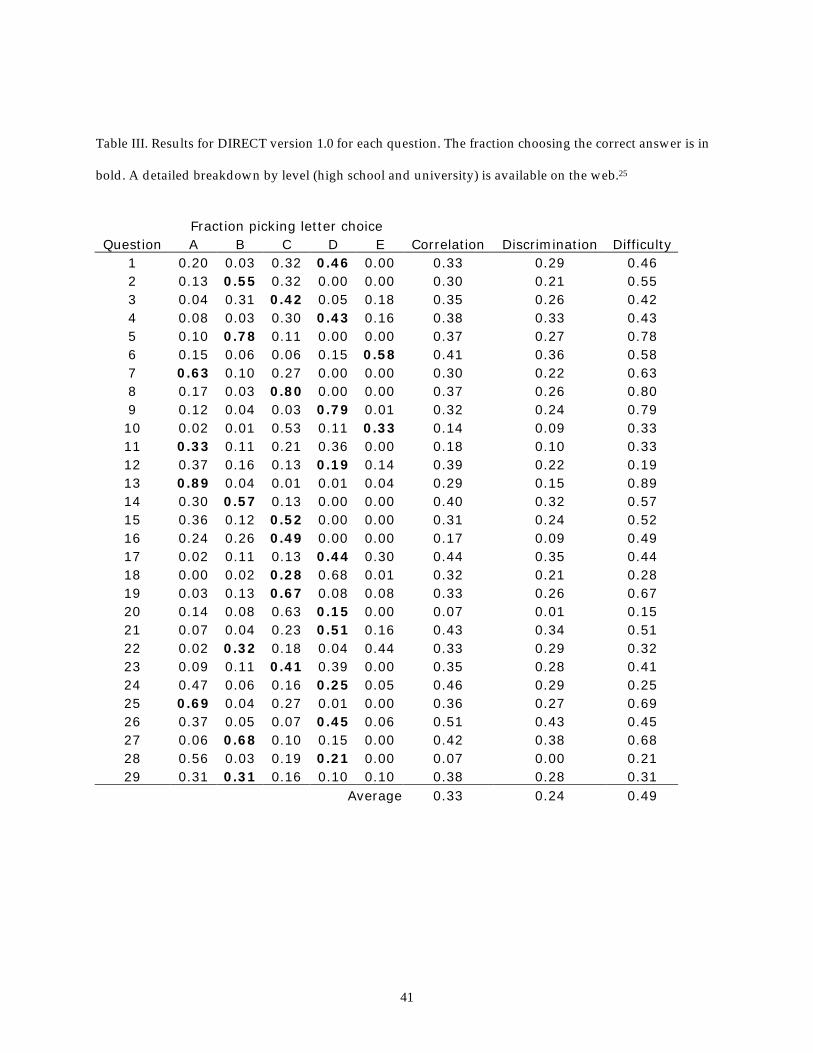
distribution of scores for the total sample, which is positively skewed, indicating
a difficult test. Table III shows the percentage of students selecting each answer
choice for each question as well as the point bi-serial correlation, discrimination,
and difficulty of each question.
DIRECT version 1.129 was developed after an analysis of the results as
well as individual follow-up interviews indicated that DIRECT version 1.0
needed to be revised to improve its reliability as well as to clarify questions that
were confusing to students. There were two main revisions. The first was to
9
increase the number of answer choices to 5 for all questions. In so doing, some
questions became more quantitative in nature, asking by how much the
brightness changed in contrast to asking if it increased/decreased or remained
the same. The second was to redraw the circuit diagrams containing a light bulb
in a socket using only the battery, bulb, and wires as the interviews indicated
that students were confused about this representation.
DIRECT version 1.1 was administered to 692 students from high schools
(N = 251) and universities (N = 441) in Canada (one high school and one
university test site), Germany (one high school test site), and the United States.
Version 1.1 consisted of 29 items, each with 5 answer choices, and took
approximately half an hour to complete. The statistical analysis of the test is
presented in Table II. Figure 3 shows the distribution of scores for the total
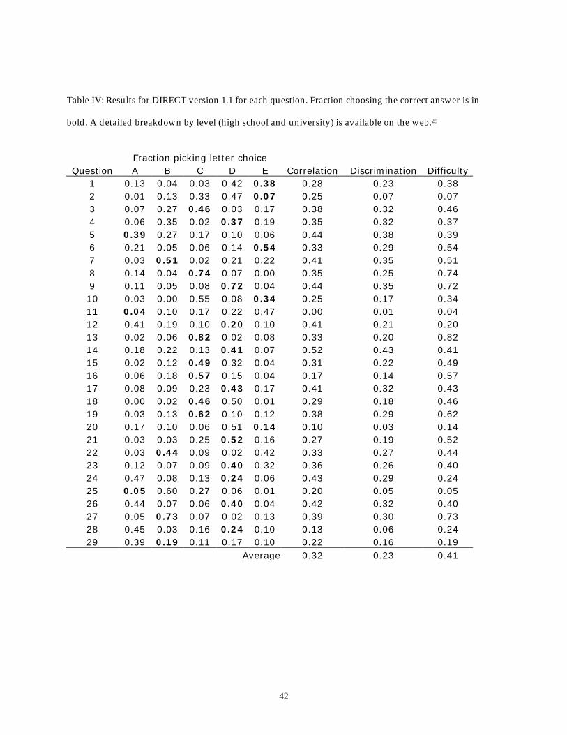
sample, which also are positively skewed, indicating a difficult test. Table IV
shows the results for version 1.1 in a similar manner to that of Table III.
III. General findings
We will next discuss the discrimination ability (how well a particular
question differentiated between students scoring well and students scoring
poorly on the test) and how well students performed on the overall objectives
listed in Table I for each version of the test.
10
IIIA. Discrimination Discrimination is a measure of the ability of a question to differentiate
between students who scored well overall on the test from those who did not.
Examining the data from version 1.0 revealed that question 26 was the most
discriminating. To answer this question correctly, students could not reason
sequentially, believe that the battery was a constant source of current, or think
that current was consumed.
For the overall sample (combined university and high school) and for the
university sample, questions 20 and 28 were the least discriminating; even
students who scored well overall on the test had difficulties with these questions.
Question 20 deals with what causes a current in a bulb filament. Students
confused cause and effect, choosing the option that the current caused the field.
Question 28 deals with the concept of the battery as a source of constant potential
difference. Many students reasoned that because the current in a part of the
circuit is zero, the voltage also is zero. For the high school sample, question 18
was the least discriminating. This question shows four circuits containing a
battery, some connecting wires, and a light bulb in a socket. Students were able
to identify complete circuits, but were unable to eliminate those that contained
shorts.
The discrimination indices for version 1.1 revealed that for the overall and
the university sample, question 14 was the most discriminating. Students who
11
answered correctly had to understand how to calculate the equivalent resistance
for resistors in a series/parallel combination and to compare the equivalent
resistance to that of two resistors in series. Question 27 was the most
discriminating for the high school sample, and explores students’ understanding
of objectives 1-3 in Table I. For all samples (overall), question 11 proved the least
discriminating, and examines the students’ understanding of the microscopic
aspects of current.
IIIB. Performance on the objectives
Table I shows how well students performed on each of the instructional
objectives for both versions 1.0 and 1.1. An examination of the distracters of both
versions showed that 17% of the students could not identify a short in a circuit
and/or determine what effect the short had on the circuit, 10% did not know
where the contacts are on a light bulb, 6% had trouble identifying a complete
circuit, and 28% exhibited current/voltage confusion.
On both versions of DIRECT, students were able to translate from a
realistic representation of a circuit to the schematic, but had more difficulty in
identifying the correct schematic from a written description of the circuit or in
identifying the correct realistic representation of a circuit from a schematic. In
general, students could identify a complete circuit. The difficulty arose when
12
students were asked to determine whether the circuit worked or not, often
including circuits that contained shorts.
IV. Can a multiple-choice test be developed that is reliable and valid and in addition uncover students’ misconceptions?
For a test to be useful, it must be both reliable and valid. Reliability is an
indication of how precisely we made the measurement or how consistently the
test measures what it measures. The Kuder-Richardson formula 20 (KR-20) was
used to evaluate the reliability of both versions of DIRECT. The KR-20 should be
at or above 0.70 for group measurements. Although this was the case for both
versions (see Table II), the somewhat low values could be the result of the low
discrimination and high difficulty indices. The low average discrimination values
may indicate that the test is indeed uncovering students’ misconceptions.
The other important and vital characteristic of any test is its validity – the
ability of the test to measure what it is intended to measure or the test’s accuracy.
Validity is not a quality that can be established in a single measurement, but is
accumulated via several measurements. Content validity (Does the test cover the
appropriate material?) was established by presenting the test and objectives to an
independent panel of experts to insure that the domain was adequately covered.
The panel took the test and matched test items with objectives. This process
yielded a percentage agreement for the answer key as well as for the objectives.
Both open-ended questions (during the early development stages) and multiple-
13
choice questions were directed to the panel. In cases where agreement on the
objectives was low, the questions were rewritten. Although each question was
written to address a particular objective, the test involves items that require the
test taker to utilize additional information not specifically asked by the question
and hence some questions by necessity addressed more than one objective.
The construct validity (Does the test measure electric circuits’ concepts
like current, voltage, etc?) of DIRECT was evaluated through a factor analysis,
which will only be discussed briefly here, and interviews. A factor analysis
analyzes the interrelationships within the data and can be used to select groups
of items that appear to measure the same idea or factor. The factor analysis
performed for both versions used the Little Jiffy method which revealed 8 factors
associated with version 1.0 and 11 factors associated with version 1.1.30 The
interviews served (1) to determine if the questions were being understood in
ways that were not intended and to better understand students’ choices and (2)
to provide evidence of the test’s construct validity by the replication of results
from previous studies.
Individual follow-up interviews using a subset of 10 questions from
version 1.0 with 17 university and 11 high school students were conducted as
part of the construct validity check. These interviews provided information on
whether the questions were being understood in ways contrary to what was
intended. Each interview lasted approximately 30 to 40 minutes and was audio
14
taped and later transcribed. Any notes that students made during the interview
were collected. The interview was semi-structured and made use of a think-
aloud procedure, which required students to verbalize aloud their thoughts as
they emerged. The interview was divided into three parts: identification of
symbols used on the test, definition of terms used on the test, and answering the
test items, providing reasoning behind their choice and their confidence on their
answer. The student’s answers to the multiple-choice test were available to the
interviewer during the interview. If students changed their answers from the
multiple-choice test, they were asked to recall what their reasoning was when
they answered the test originally. To ensure a uniform coding of the interview
transcripts, another researcher was asked to code the transcripts. The reliability
of the coding between the two researchers was established with 15% of the
sample at each level (high school and university) with a percentage agreement of
88%.
The interviews showed that nearly all of the students understood the
symbols used on the test with the exception of the light bulb in a socket; two-
thirds knew that a light bulb had two connections; and one-third believed that
there was only one connection which was located at the bottom of the bulb.
The interviews were able to replicate results of previous studies. For
example, some students who chose option E on question 3 reasoned via battery
superposition, replicating the results of Sebastià.11 The following is an example of
15
a student using the battery as a superposition idea for question 3. The student in
the excerpt was enrolled in a traditional, calculus-based course.
“I think I would put E because the batteries are providing the energy so since they both have two two [sic] batteries. I didn’t think that it would matter whether they were in parallel or series because they’re gonna add a certain amount of voltage and when the parallel batteries link up it’s gonna be equivalent to whatever voltage is added when they are in series and then the light bulbs since they are just two in series, that’s the same for all three pictures.”
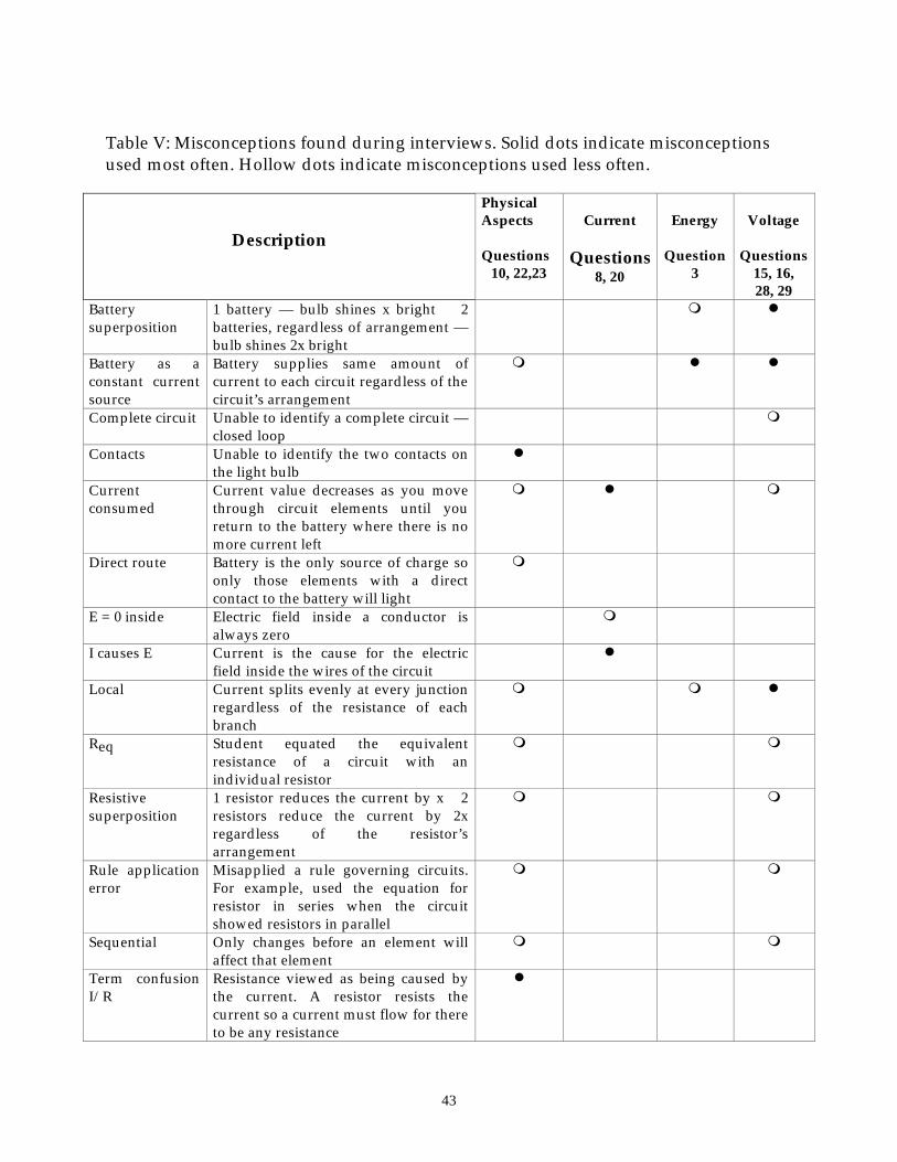
In reviewing the results obtained from the follow-up interviews with
version 1.0, there initially appeared to be no pattern to the students’ reasoning on
the interviewed questions. However, examining which misconception was used
most often on each question and comparing them with the global objectives (see
Table V) for each question did yield a pattern. Table V shows the four main
divisions or global objectives: physical aspects of the circuit, energy, current, and
potential difference (voltage), and the misconceptions that were cued for the
interview questions posed. For the global objective of voltage, the dominant
misconceptions for these questions were battery as a constant current source,
term confusion I with V, local reasoning, and battery superposition. These
misconceptions relate to students’ understanding of the properties of the battery
and what it supplies to the circuit. Similarly, for the global objective of physical
aspects of the circuit, typical misconceptions were topology, contacts, and term
confusion I/R. These misconceptions related to the physical features of the circuit.
16
The topological errors indicated that students looked at the surface features of
the circuit. The contact error indicated that students were missing some
knowledge of where the contacts are located on a light bulb. Term confusion I
with R errors indicated that students did not understand that a resistor (including
light bulbs) has an inherent resistance based on its shape and the material from
which it is made. One could categorize errors associated with the physical
aspects of the circuits as students not having the declarative knowledge needed
to understand the physical nature of the circuit diagram and its associated
elements. Thus, although different questions cued the use of different
misconceptions, the students tended to use misconceptions associated with the
global objective of the question.
To summarize, there is evidence that both versions of DIRECT are reliable
and valid. Both versions appear to be able to illicit students’ conceptual
understanding of DC resistive electric circuits concepts.
V. Are there significant differences between level (High School versus University), gender, and instructional methods? To answer this question, a series of t-tests and ANOVA were used to
determine if there were significant differences between various groups of
students who had taken DIRECT versions 1.0 and 1.1. Groups were considered
significantly different if the level of significance or p-value was at or below 0.05,
which gives a 95% level of confidence that the difference is real. All t-tests
17
assumed a one-tail test of significance so that the superiority of one group over
the other could be determined. Students’ raw scores were used in these
calculations, so that a score of 29 is equivalent to 100%.
VA. Level (High school compared to university)
For version 1.0, there were significant differences in the averages for the
university (M = 15) and high school groups (M = 12), t (1008) = 11, p < 3.8 x 10⁻²⁸,
with university students outperforming high school students. There were no
significant differences between calculus-based (M = 16) and algebra-based
(M = 15) university students, t (191) = -1.6, p < 0.06. No significant differences
were found between the Advanced Placement or honors high school students (M
= 12) and those high school students taking a regular physics class (M = 13),
t (342) = -0.89, p < 0.19. Similar results were obtained for version 1.1. The analysis
of interview results found no significant differences in the number of
misconceptions used by university (M = 8) and high school students (M = 9),
t (23) = -0.73, p < 0.24. However, university students were significantly (p < 0.006)
more confident in their interview answers than were the high school students.
VB. Gender
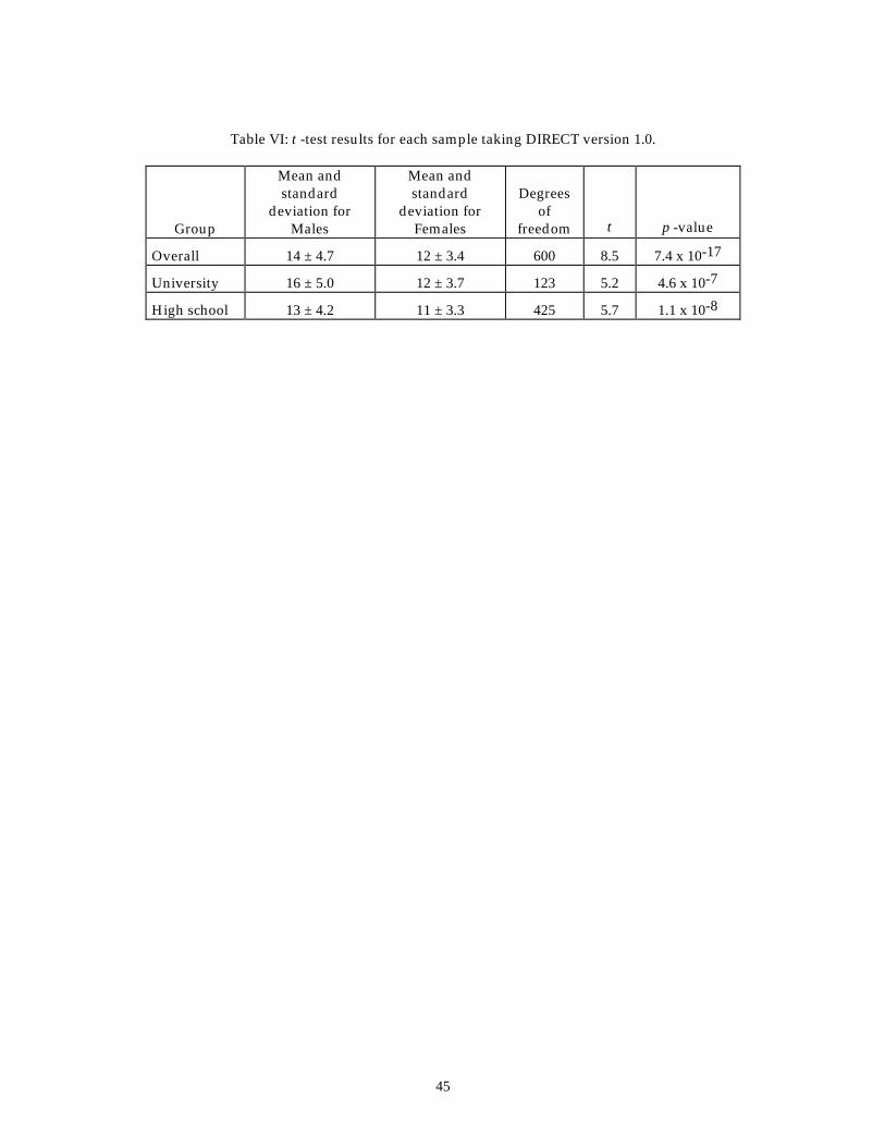
For version 1.0, significant differences were found in the averages for
males and females with males outperforming females at all levels (see Table VI).
18
Interview results indicated significant differences between the number of
misconceptions used by males (M = 6) and females (M = 11), t(25) = 3.9,
p < 0.0003, with females using more than males. A similar finding was found for
university males (M = 6) and females (M = 11), t (11) = 3.6, p < 0.002. However,
there were no significant differences found between high school males (M = 6)
and females (M = 10), t (4) = 1.4, p < 0.12. Males were more confident in their
interview responses than were females (p < 0.0006).
VC. Instructional method
To evaluate the feasibility of using DIRECT to evaluate curricular
materials and to assess new teaching methods, several subgroups who took
DIRECT 1.0 and 1.1 were chosen for further examination. Part of the DIRECT 1.0
university sample contained a small group of calculus-based students who used
a Chabay and Sherwood text26, which discusses the microscopic aspects of circuit
phenomena. We found that there were significant differences between students
using the Chabay and Sherwood text (M = 18) and students using more
traditional textbooks (M = 15), t (76) = -3.8, p < 0.0001, as well as the university
group as a whole (algebra and calculus-based combined) (M = 15), t (44) = -4.2, p
< 6.1 x 10⁻⁵. Those students using the Chabay and Sherwood textbook
outperformed both groups.
19
There was a small group of students who used the Physics by Inquiry
materials, which uses an inquiry approach to instruction with many hands-on
activities. This small group of students took DIRECT version 1.1. An analysis of
variance (ANOVA) was performed which allows one to compare the means of
more than two groups. Our results showed that there were significant
differences between the students using the Physics by Inquiry materials (M =15),
calculus-based students (M =13), and algebra-based students (M =12), F (2, 438) =
4.13, p < 0.017. Those students using Physics by Inquiry outperformed both
groups.
This examination of various subgroups that used new curricular materials
showed that there were statistically significant differences between their scores
and students who were taking more traditional courses. These results are only
preliminary and were performed to evaluate if DIRECT could be used in this
way. More rigorously designed studies would need to be developed to further
evaluate the apparent differences between these subgroups and other students.
DIRECT appears to be able to assess differences between groups of students
using differing instructional methods and materials.
VI. What misconceptions can the test detect?
20
We now discuss the difficulties and misconceptions that DIRECT can
detect. The interview results showed a variety of difficulties students
experienced with a subset of questions from DIRECT 1.0 as shown in Table V.
A comparison of students’ definitions of terms used on DIRECT and the
student misconceptions indicates that the main source of the difficulty is with
term confusion, generally associated with current. Students assign the properties
of energy to current, and then assign these properties to voltage and resistance.
Specifically, both voltage and resistance can only occur in the presence of a
current.
Students do not have a clear understanding of the underlying mechanisms
of electric circuits. This misunderstanding is most likely the result of a weak
connection between electrostatics and electrokinetics phenomena, as this
connection is only now beginning to be addressed in some of the newer
textbooks.
Students were able to translate easily from a realistic representation of a
circuit to the corresponding schematic diagram. Students had difficulty making
the reverse translation. However, this result may be more indicative of their
difficulty identifying shorts within circuits or of deficiencies in their knowledge
regarding the contacts for light bulbs.
One aspect of DIRECT that sets it apart from other tests that have been
developed is the use of batteries connected in series or parallel. This inclusion
21
allows one to investigate how students interpret voltage and current in circuits
containing these elements. Results from version 1.0 indicated that students had
difficulty predicting the resulting voltage and current. Interviews indicated that
some of the students were using superposition reasoning, while others were
using a combination of battery as a constant current source and local reasoning.
Hand-written notes made by the students during the interviews indicated that
some students may have been trying to apply rules for equivalent resistors or
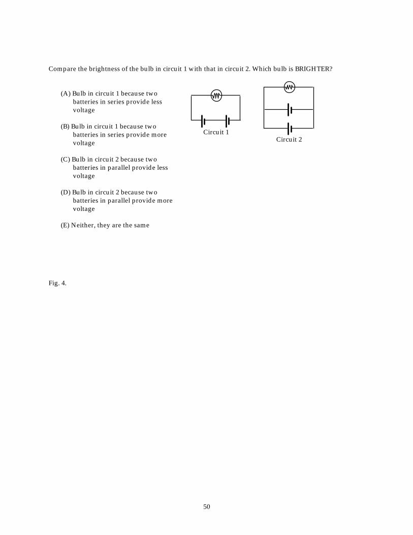
capacitors to the battery arrangements. Version 1.1 explored further distinctions
between two batteries in series and two batteries in parallel through questions 3
(in its original form) and question 7 (see Fig. 4). Results from these questions
indicated the following:
1) Students who believe that two batteries in parallel provide more energy (27%) also believe that they provide more voltage (21%) (Pearson r = 0.37).
2) Students who believe that two batteries in series provide more
energy (46%) also believe that they provide more voltage (51%) (Pearson r = 0.45).
3) Students who believe that two batteries in series and two
batteries in parallel provide the same energy (17%) also believe that they provide same voltage (22%) (Pearson r = 0.41).
Those questions containing multiple batteries were items questioned by the
independent panel of experts. They were concerned that this use might diminish
the results of the test because multiple batteries are not typically taught.
However, the ideas necessary to analyze these circuits are presented in most
22
courses. The ideas are that the potential difference in two parallel branches
remains the same while the currents in the parallel branches add to equal the
total current available, and the potential difference across each element in series
adds to equal the total input from the battery while the current remains the same.
These ideas are used in a number of the problems and were acknowledged by
the panel of experts as important to include on the test. Thus, if students truly
understand these concepts, they should be able to apply them to novel situations.
VII. Conclusions and Implications
Both versions of DIRECT appear to be reliable and valid. Results indicate
that either version could be useful in evaluating curriculum or instructional
methods as well as providing insight into students’ conceptual understanding of
DC circuit phenomena.
Interview results indicated that students use the idea that the battery is a
constant current source most often in solving the interview problems. Students
were found to use different misconceptions depending on the problem
presented. Thus, different questions cued different misconceptions. Although
students tended to use different misconceptions for each question presented,
they did tend to use misconceptions related to the global objective of the
question.
23
There are differences associated with gender in terms of performance,
number of misconceptions used, and confidence and with course level with
regard to performance and confidence. Generally, males outperformed females
and had more confidence in their responses than did females. Females tended to
use more misconceptions. Performance differences were found on both versions
of DIRECT with university students outperforming high school students.
University students also had more confidence in their answer selections.
In revising DIRECT 1.0, the number of answer choices was increased to
five for all questions. In so doing, some questions became less qualitative and
more quantitative. Instead of asking does the brightness increase, decrease, or
stay the same, the questions asked by how much the brightness changed (1/4,
1/2, 2, 4, same). This quantification of some items was the main difference
between version 1.0 and 1.1. These items accounted for the difference in scores
between the two versions. Changes to other items resulted in only minor
fluctuations. Some of the questions on DIRECT 1.1 required students to analyze
simultaneous changes in variables, like voltage and resistance or current and
voltage. Other questions required that students be proficient in their use of
ratios.31 Results indicated that students had difficulty with this analysis. The
follow-up interviews indicated students’ preference for and reliance on formulas.
Version 1.0 is more qualitative and seems to elicit the misconceptions
more directly while version 1.1 is more quantitative and seems to elicit the
24
students’ mathematical abilities to some extent. If one is more interested in the
conceptual understanding of circuits, version 1.0 and newer versions patterned
after it would be the better alternative. However, if the students’ mathematical
abilities were of interest, then version 1.1 would be the appropriate choice.
We want to stress that DIRECT is not the end-all-be-all of tests. It simply
provides another data point for instructors and researchers to use to evaluate the
progress of students’ understanding. No one instrument or study can provide
definitive answers. Data regarding students’ understanding should be
considered like evidence of validity--requiring several measurements through
different means to arrive at the final answer.
Acknowledgements
The authors would like to acknowledge all the students and instructors
who were involved in field testing DIRECT. Without their cooperation, this
project would not have been possible. We would also like to thank the members
of the independent panel of experts for their helpful and insightful feedback.
1 D. Hestenes, M. Wells, and G. Swackhamer, “Force concept inventory,” Phys. Teach. 30 (3), 141-58 (1992).
2 R.J. Beichner, “Testing student interpretation of kinematics graphs,” Am. J. Phys, 62 (8), 750-762 (1994).
25
3 P. V. Engelhardt, “Examining students’ understanding of electrical circuits through multiple-choice testing and interviews,” unpublished doctoral dissertation, North Carolina State University (1997). The interested reader can read a more in-depth literature review in Chap. 2.
4 M. Arnold and R. Millar, “Being constructive: An alternative approach to the teaching of introductory ideas in electricity,” Int. J. Sci. Educ. 9 (5), 553-63. (1987); N. Fredette and J. Lochhead, “Student conceptions of simple circuits,” Phys. Teach. 18 (3), 194-8 (1980); C. Kärrqvist, “Pupils are able,” in Proceedings of the Second International Seminar on Misconceptions and Educational Strategies in Science and Mathematics, edited by J. Novak (Cornell University, Ithaca, NY, 1987), pp. 293-96; L.C. McDermott and E. H. van Zee, “Identifying and addressing student difficulties with electric xircuits,” in Aspects of Understanding Electricity: Proceedings of an International Workshop, Ludwigsburg, Germany, edited by R. Duit, W. Jung, and C. von Rhöneck (Vertrieb Schmidt and Klaunig, Kiel, Germany, 1984), pp. 39-48; R. Osborne, “Children’s ideas about electric current,” New Zealand Science Teacher 29, 12-19, (1981); D. M. Shipstone, “A study of children’s understanding of electricity in simple DC circuits,” Eur. J. Sci. Educ. 6 (2), 185-198 (1984).
5 P. Licht and G. D. Thijs, “Method to trace coherence and persistence of preconceptions,” Int. J. Sci. Educ. 12 (4), 403-416 (1990); R. Cohen, B. Eylon, and U. Ganiel, “Potential difference and current in simple electric circuits: A study of student’s concepts,” Am. J. Phys. 51 (5), 407-412 (1983); J. J. Dupin and S. Johsua, “Conceptions of French pupils concerning electric circuits: Structure and evolution,” J. Res. Sci. Teach. 24 (9), 791-806 (1987). 6 C. von Rhöneck and B. Völker, “Semantic structures describing the electric circuit before and after instruction,” in Aspects of Understanding Electricity: Proceedings of an International Workshop, Ludwigsburg, Germany, edited by R. Duit, W. Jung, and C. von Rhöneck (Vertrieb Schmidt and Klaunig, Kiel, Germany, 1984), pp. 95-106; W. Jung, “Category questionnaires - The technique and some results,” ibid., pp. 197-204; P. M. Heller and F. N. Finley, “Variable uses of alternative conceptions: A case study in current electricity,” J. Res. Sci. Teach. 29 (3), 259-75 (1992).
7 S. Johsua, ”Students’ interpretation of simple electrical diagrams,” Eur. J. Sci. Educ. 6 (3), 271-275 (1984).
8 M. Caillot, “Problem representations and problem-solving procedures in electricity,” in Aspects of Understanding Electricity, Proceedings of an International Workshop, R. Duit, W. Jung, and C. von Rhöneck (Vertrieb Schmidt and Klaunig, Kiel, Germany, 1984), pp. 139-151; L. C. McDermott and P. S. Shaffer, “Research as a guide for curriculum development: An example from introductory electricity. Part I: Investigation of student understanding,” Am. J. Phys. 60 (11), 994-1003 (1992). 9 See McDermott and Shaffer, Ref. 7.
10 R. Gott, “The place of electricity in the assessment of performance in science,” in Aspects of Understanding Electricity, Proceedings of an International Workshop, edited by R. Duit, W. Jung, and C. von Rhöneck (Vertrieb Schmidt & Klaunig, Kiel, Germany, 1984), pp. 49-61.
26
11 P. M. Heller and F. N. Finley, “Variable uses of alternative conceptions: A case study in current electricity,” J. Res. Sci. Teach. 29 (3), 259-75 (1992); L.C. McDermott and P. S. Shaffer, “Research as a guide for curriculum development: An example from introductory electricity. Part I: Investigation of student understanding,” Am. J. Phys. 60 (11), 994-1003 (1992).
12 J. L. Closset, “Sequential reasoning in electricity,” in Research on Physics Education: Proceedings of the First International Workshop (Editions du Centre National de la Recherche Scientifique, La Londe les Maures, France ,1984), pp. 313-319; D. M. Shipstone, “A study of children’s understanding of electricity in simple DC circuits,” Eur. J. Sci. Educ. 6 (2), 185-198 (1984).
13 C. von Rhöneck and K. Grob, “Representation and problem-solving in basic electricity, predictors for successful learning” in Proceedings of the Second International Seminar on Misconceptions and Educational Strategies in Science and Mathematics, edited by J. D. Novak (Cornell University, Ithaca, NY, 1987), p. 564.
14 J. M. Sebastià, “Cognitive mediators and interpretations of electric circuits,” in Proceedings of the Third International Seminar on Misconceptions and Educational Strategies in Science and Mathematics (Misconceptions Trust, Ithaca, NY, 1993). 15R. Cohen, B. Eylon, and U. Ganiel, “Potential difference and current in simple electric circuits: A study of student’s concepts,” Am. J. Phys. 51 (5), 407-412 (1983); R. Millar and K. L. Beh, “Students’ understanding of voltage in simple parallel electric circuits,” Intl. J. Sci. Educ. 15 (4), 351-361 (1993); H. F. van Aalst, “The differentiation between connections in series and in parallel from cognitive mapping; Implications for teaching,” in Aspects of Understanding Electricity, Proceedings of an International Workshop, edited by R. Duit, W. Jung, and C. von Rhöneck (Vertrieb Schmidt & Klaunig, Kiel, Germany, 1984), pp. 115-128. 16 Ref. 14, van Aalst, p. 124. 17 Arnold B. Arons, Teaching Introductory Physics (John Wiley & Sons, NY, 1997), p. 4.
18 R. Cohen, B. Eylon, and U. Ganiel, “Potential difference and current in simple electric circuits: A study of student’s concepts,” Am. J. Phys. 51 (5), 407-412 (1983); J. J. Dupin and S. Johsua, “Conceptions of French pupils concerning electric circuits: Structure and evolution,” J. Res. Sci. Teach. 24 (9), 791-806 (1987); K. Grob, V. L. Pollack, and C. von Rhöneck, “Computerized analysis of students’ ability to process information in the area of basic electricity,” in Proceedings of the Research in Physics Learning: Theoretical Issues and Empirical Studies , edited by F. G. Reinders Duit Hans Niedderer [xx one name? xx] (The Institute for Science Education at the University of Kiel, Kiel, Germany, 1991), pp. 296-309; S.M. Lea, B.A. Thacker, E. Kim, and K. M. Miller, “Computer-assisted assessment of student understanding in physics,” Computers in Physics 8 (1), 122-127 (1994); P. Licht and G. D. Thijs, “Method to trace coherence and persistence of preconceptions,” Intl. J. Sci. Educ. 12 (4), 403-416 (1990); R. Millar and T. King, “Students’ understanding of voltage in simple series electric circuits,” Intl. J. Sci. Educ. 15 (3), 339-349 (1993); D. R. Sokoloff, “RealTime [xx one word or 2? xx] physics electricity: Active learning of electric circuit concepts
27
using microcomputer-based current and voltage probes,” to be published in La Fisica Nella Scuola (1994); [xx 1994? xx] M. S. Steinberg and C. L. Wainwright, “Using models to teach electricity: The CASTLE project,” Phys. Teach. 31 (9), 353-57 (1993).
19 A. H. Johnstone and A.R. Mughol, “The concept of electrical resistance,” Phys. Educ. 13, 46-49 (1978).
20 D. M. Shipstone, C. von Rhöneck, W. Jung, C. Kärrqvist, J. J. Dupin, S. Johsua, and P. Licht, “A study of students’ understanding of electricity in five European countries,” Intl. J. Sci. Educ. 10 (3), 303-16 (1988).
21 P. S. Shaffer and L. C. McDermott, “Research as a guide for curriculum development: An example from introductory electricity. Part II: Design of instructional strategies,” Am. J. Phys. 60 (11), 1003-13 (1992).
22 L. C. McDermott and P. S. Shaffer, “Research as a guide for curriculum development: An example from introductory electricity. Part I: Investigation of student understanding,” Am. J. Phys. 60 (11), 999-1000 (1992).
23 D. Psillos, P. Koumaras, and O. Valassiades, “Pupils’ representations of electric current before, during and after instruction on DC circuits,” Res. Sci. and Technological Educ. 5 (2), 193 (1987).
24 L. C. McDermott et al., Physics by Inquiry (John Wiley & Sons, NY, 1996), Vol. II. 25 R. A. Serway and J. S. Faughn, College Physics (Saunders College Publishing, NY, 1985).
26 R. Chabay and B. Sherwood, Electric & Magnetic Interactions (John Wiley & Sons, NY, 1995).
27 R. Cohen, B. Eylon, and U. Ganiel, “Potential difference and current in simple electric circuits: A study of student’s concepts,” Am. J. Phys. 51 (5), 407-412 (1983).
28 J. W. Best, Research in Education (Prentice-Hall, Englewood Cliffs, NJ, 1981), 4th ed., p. 14.
29 DIRECT version 1.1 is available from <http://www.ncsu.edu/PER>. 30 These results and the accompanying tables are available at <http://www.ncsu.edu/PER>. Files containing both versions of the test are also available.
31 A. B. Arons, A Guide to Introductory Physics Teaching (John Wiley & Sons, NY, 1990), pp. 3-6.
28
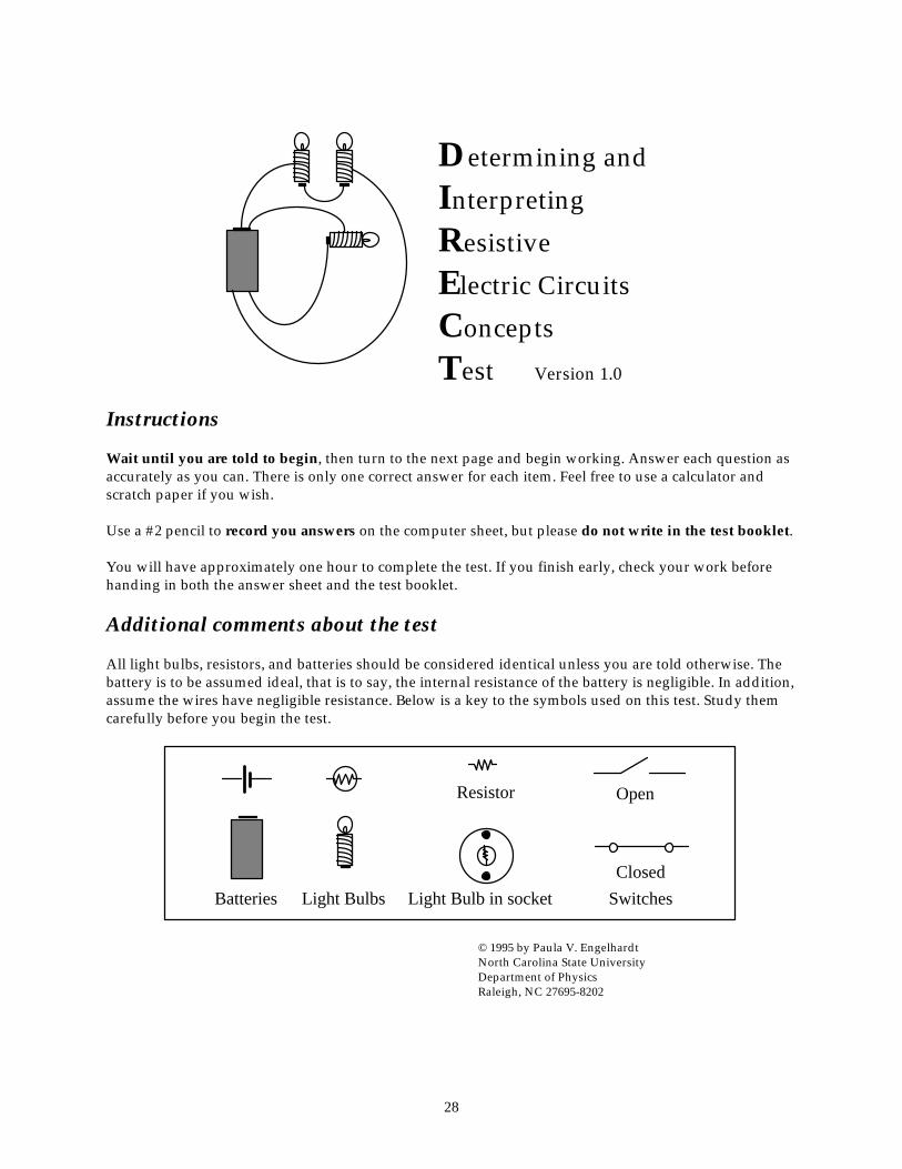
Determining and
Interpreting Resistive Electric Circuits Concepts Test Version 1.0
Instructions Wait until you are told to begin, then turn to the next page and begin working. Answer each question as accurately as you can. There is only one correct answer for each item. Feel free to use a calculator and scratch paper if you wish. Use a #2 pencil to record you answers on the computer sheet, but please do not write in the test booklet. You will have approximately one hour to complete the test. If you finish early, check your work before handing in both the answer sheet and the test booklet. Additional comments about the test All light bulbs, resistors, and batteries should be considered identical unless you are told otherwise. The battery is to be assumed ideal, that is to say, the internal resistance of the battery is negligible. In addition, assume the wires have negligible resistance. Below is a key to the symbols used on this test. Study them carefully before you begin the test.
Batteries Light Bulbs
Resistor
Light Bulb in socket SwitchesClosed
Open
© 1995 by Paula V. Engelhardt North Carolina State University Department of Physics Raleigh, NC 27695-8202
29
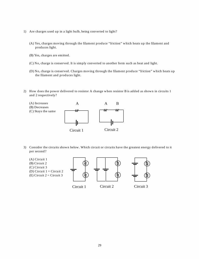
1) Are charges used up in a light bulb, being converted to light?
(A) Yes, charges moving through the filament produce “friction” which heats up the filament and produces light.
(B) Yes, charges are emitted.
(C) No, charge is conserved. It is simply converted to another form such as heat and light.
(D) No, charge is conserved. Charges moving through the filament produce “friction” which heats up the filament and produces light.
2) How does the power delivered to resistor A change when resistor B is added as shown in circuits 1
and 2 respectively?
(A) Increases (B) Decreases (C) Stays the same
A
Circuit 1
A
Circuit 2
B
3) Consider the circuits shown below. Which circuit or circuits have the greatest energy delivered to it
per second?
(A) Circuit 1 (B) Circuit 2 (C) Circuit 3 (D) Circuit 1 = Circuit 2 (E) Circuit 2 = Circuit 3
Circuit 1 Circuit 2 Circuit 3
30
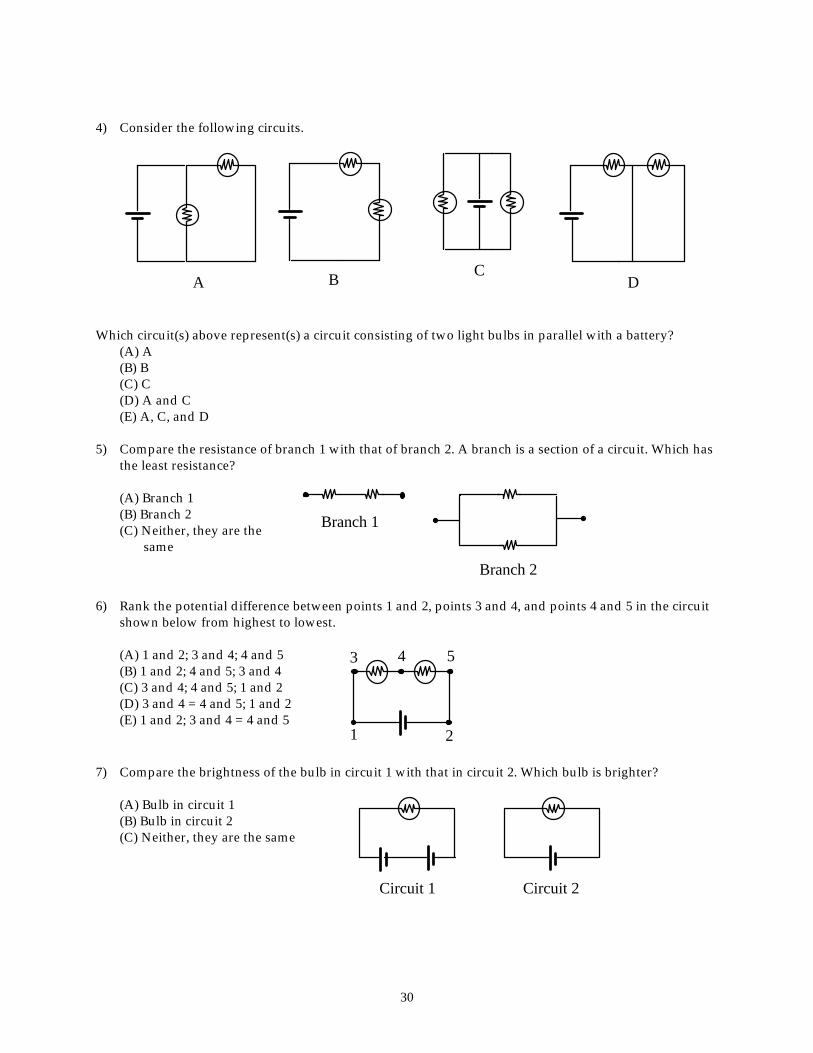
4) Consider the following circuits.
A B
C D Which circuit(s) above represent(s) a circuit consisting of two light bulbs in parallel with a battery? (A) A (B) B (C) C (D) A and C (E) A, C, and D 5) Compare the resistance of branch 1 with that of branch 2. A branch is a section of a circuit. Which has
the least resistance?
(A) Branch 1 (B) Branch 2 (C) Neither, they are the
same
Branch 1
Branch 2 6) Rank the potential difference between points 1 and 2, points 3 and 4, and points 4 and 5 in the circuit
shown below from highest to lowest.
(A) 1 and 2; 3 and 4; 4 and 5 (B) 1 and 2; 4 and 5; 3 and 4 (C) 3 and 4; 4 and 5; 1 and 2 (D) 3 and 4 = 4 and 5; 1 and 2 (E) 1 and 2; 3 and 4 = 4 and 5
21
3 4 5
7) Compare the brightness of the bulb in circuit 1 with that in circuit 2. Which bulb is brighter?
(A) Bulb in circuit 1 (B) Bulb in circuit 2 (C) Neither, they are the same
Circuit 1 Circuit 2
31
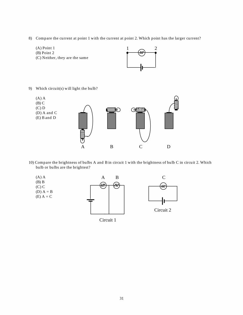
8) Compare the current at point 1 with the current at point 2. Which point has the larger current?
(A) Point 1 (B) Point 2 (C) Neither, they are the same
1 2
9) Which circuit(s) will light the bulb?
(A) A (B) C (C) D (D) A and C (E) B and D
A CB D 10) Compare the brightness of bulbs A and B in circuit 1 with the brightness of bulb C in circuit 2. Which
bulb or bulbs are the brightest?
(A) A (B) B (C) C (D) A = B (E) A = C
BA
Circuit 1
C
Circuit 2
32
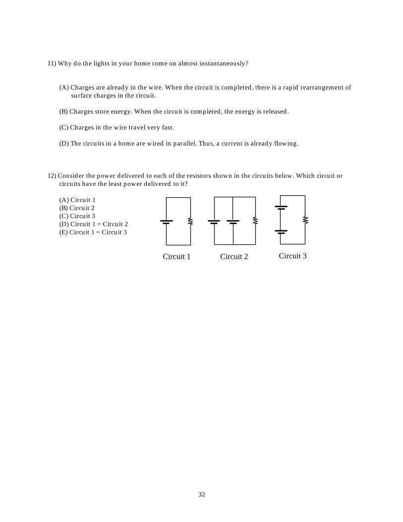
11) Why do the lights in your home come on almost instantaneously?
(A) Charges are already in the wire. When the circuit is completed, there is a rapid rearrangement of surface charges in the circuit.
(B) Charges store energy. When the circuit is completed, the energy is released.
(C) Charges in the wire travel very fast.
(D) The circuits in a home are wired in parallel. Thus, a current is already flowing. 12) Consider the power delivered to each of the resistors shown in the circuits below. Which circuit or
circuits have the least power delivered to it?
(A) Circuit 1 (B) Circuit 2 (C) Circuit 3 (D) Circuit 1 = Circuit 2 (E) Circuit 1 = Circuit 3
Circuit 2 Circuit 3Circuit 1
33
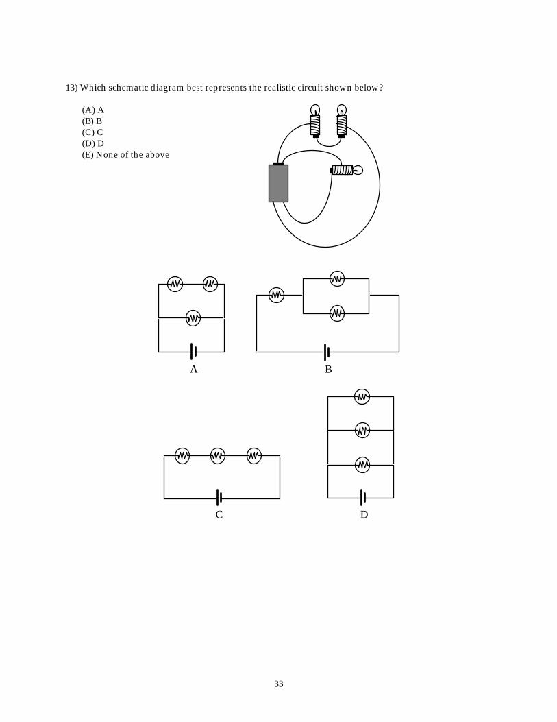
13) Which schematic diagram best represents the realistic circuit shown below?
(A) A (B) B (C) C (D) D (E) None of the above
A B
C D
34
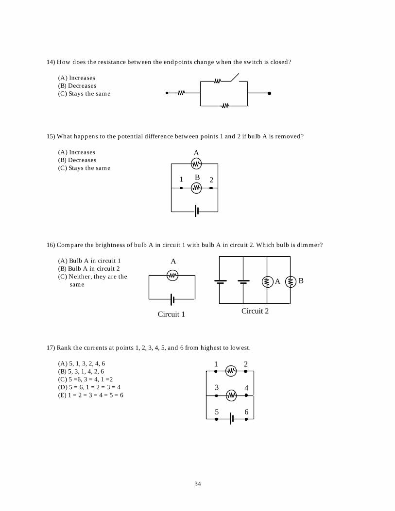
14) How does the resistance between the endpoints change when the switch is closed?
(A) Increases (B) Decreases (C) Stays the same
15) What happens to the potential difference between points 1 and 2 if bulb A is removed?
(A) Increases (B) Decreases (C) Stays the same
1 2
A
B
16) Compare the brightness of bulb A in circuit 1 with bulb A in circuit 2. Which bulb is dimmer?
(A) Bulb A in circuit 1 (B) Bulb A in circuit 2 (C) Neither, they are the
same
A
Circuit 1
A B
Circuit 2 17) Rank the currents at points 1, 2, 3, 4, 5, and 6 from highest to lowest.
(A) 5, 1, 3, 2, 4, 6 (B) 5, 3, 1, 4, 2, 6 (C) 5 =6, 3 = 4, 1 =2 (D) 5 = 6, 1 = 2 = 3 = 4 (E) 1 = 2 = 3 = 4 = 5 = 6
1
3
2
4
5 6
35
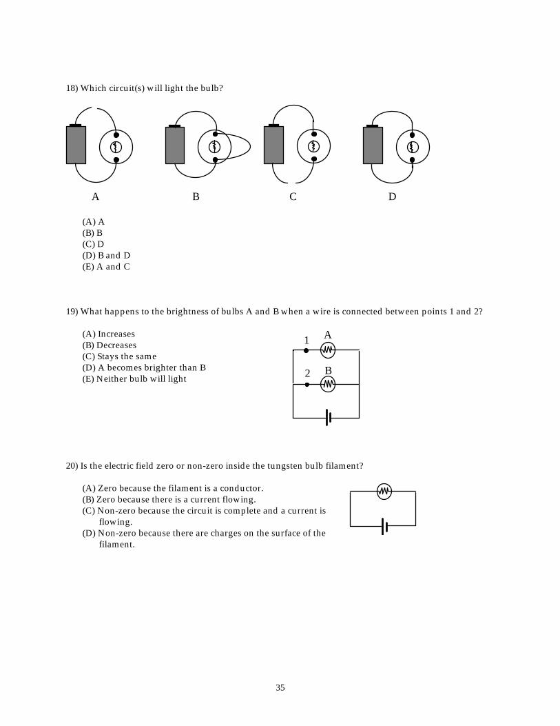
18) Which circuit(s) will light the bulb?
A B C D (A) A (B) B (C) D (D) B and D (E) A and C 19) What happens to the brightness of bulbs A and B when a wire is connected between points 1 and 2?
(A) Increases (B) Decreases (C) Stays the same (D) A becomes brighter than B (E) Neither bulb will light
1
2
A
B
20) Is the electric field zero or non-zero inside the tungsten bulb filament?
(A) Zero because the filament is a conductor. (B) Zero because there is a current flowing. (C) Non-zero because the circuit is complete and a current is
flowing. (D) Non-zero because there are charges on the surface of the
filament.
36
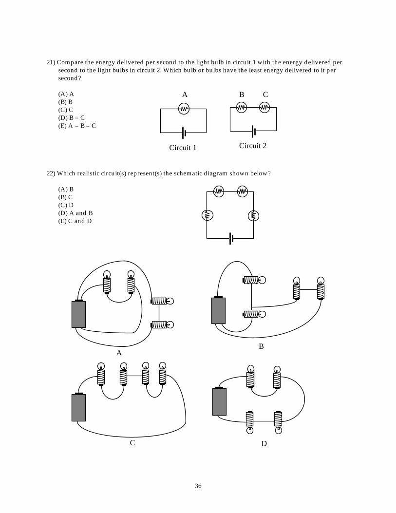
21) Compare the energy delivered per second to the light bulb in circuit 1 with the energy delivered per second to the light bulbs in circuit 2. Which bulb or bulbs have the least energy delivered to it per second?
(A) A (B) B (C) C (D) B = C (E) A = B = C
A
Circuit 1
B
Circuit 2
C
22) Which realistic circuit(s) represent(s) the schematic diagram shown below?
(A) B (B) C (C) D (D) A and B (E) C and D
A
C D
B
37
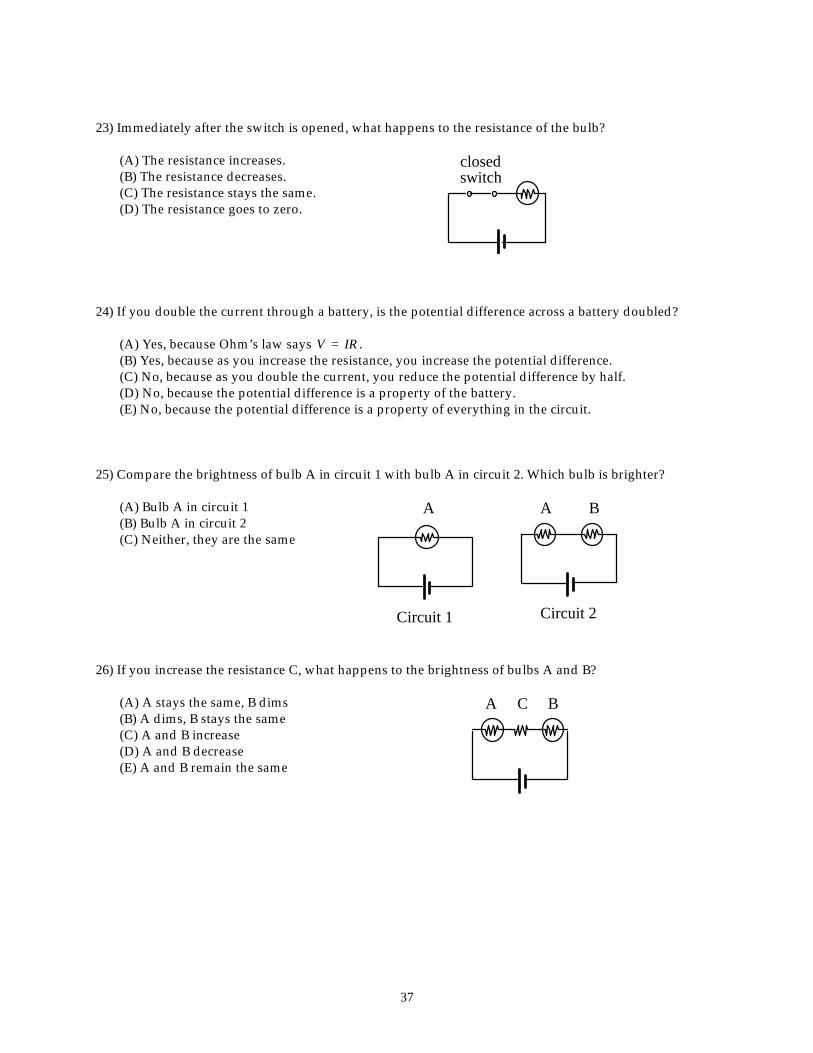
23) Immediately after the switch is opened, what happens to the resistance of the bulb?
(A) The resistance increases. (B) The resistance decreases. (C) The resistance stays the same. (D) The resistance goes to zero.
switchclosed
24) If you double the current through a battery, is the potential difference across a battery doubled?
(A) Yes, because Ohm’s law says V = IR . (B) Yes, because as you increase the resistance, you increase the potential difference. (C) No, because as you double the current, you reduce the potential difference by half. (D) No, because the potential difference is a property of the battery. (E) No, because the potential difference is a property of everything in the circuit.
25) Compare the brightness of bulb A in circuit 1 with bulb A in circuit 2. Which bulb is brighter?
(A) Bulb A in circuit 1 (B) Bulb A in circuit 2 (C) Neither, they are the same
A
Circuit 1
A
Circuit 2
B
26) If you increase the resistance C, what happens to the brightness of bulbs A and B?
(A) A stays the same, B dims (B) A dims, B stays the same (C) A and B increase (D) A and B decrease (E) A and B remain the same
A C B

38
27) Will all the bulbs be the same brightness?
A B C D
(A) Yes, because they all have the same type of circuit wiring. (B) No, because only B will light. The connections to A, C, and D are not correct. (C) No, because only D will light. D is the only complete circuit. (D) No, C will not light but A, B, and D will.
28) What is the potential difference between points A and B?
(A) 0 V (B) 3 V (C) 6 V (D) 12 V
A
B
12 V 29) What happens to the brightness of bulbs A and B when the switch is closed?
(A) A stays the same, B dims (B) A brighter, B dims (C) A and B increase (D) A and B decrease (E) A and B remain the same
A
B
C
39
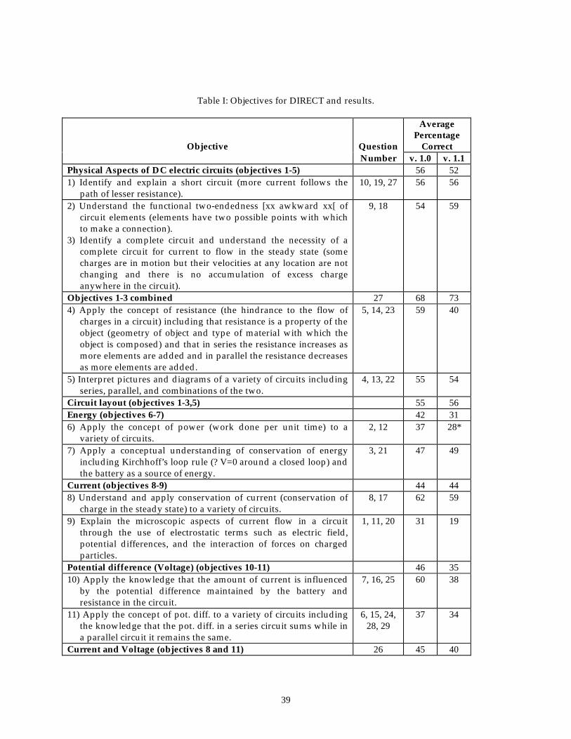
Table I: Objectives for DIRECT and results.
Objective
Question
Average Percentage
Correct Number v. 1.0 v. 1.1
Physical Aspects of DC electric circuits (objectives 1-5) 56 52 1) Identify and explain a short circuit (more current follows the
path of lesser resistance). 10, 19, 27 56 56
2) Understand the functional two-endedness [xx awkward xx[ of circuit elements (elements have two possible points with which to make a connection).
3) Identify a complete circuit and understand the necessity of a complete circuit for current to flow in the steady state (some charges are in motion but their velocities at any location are not changing and there is no accumulation of excess charge anywhere in the circuit).
9, 18 54 59
Objectives 1-3 combined 27 68 73 4) Apply the concept of resistance (the hindrance to the flow of
charges in a circuit) including that resistance is a property of the object (geometry of object and type of material with which the object is composed) and that in series the resistance increases as more elements are added and in parallel the resistance decreases as more elements are added.
5, 14, 23 59 40
5) Interpret pictures and diagrams of a variety of circuits including series, parallel, and combinations of the two.
4, 13, 22 55 54
Circuit layout (objectives 1-3,5) 55 56 Energy (objectives 6-7) 42 31 6) Apply the concept of power (work done per unit time) to a
variety of circuits. 2, 12 37 28*
7) Apply a conceptual understanding of conservation of energy including Kirchhoff’s loop rule (? V=0 around a closed loop) and the battery as a source of energy.
3, 21 47 49
Current (objectives 8-9) 44 44 8) Understand and apply conservation of current (conservation of
charge in the steady state) to a variety of circuits. 8, 17 62 59
9) Explain the microscopic aspects of current flow in a circuit through the use of electrostatic terms such as electric field, potential differences, and the interaction of forces on charged particles.
1, 11, 20 31 19
Potential difference (Voltage) (objectives 10-11) 46 35 10) Apply the knowledge that the amount of current is influenced
by the potential difference maintained by the battery and resistance in the circuit.
7, 16, 25 60 38
11) Apply the concept of pot. diff. to a variety of circuits including the knowledge that the pot. diff. in a series circuit sums while in a parallel circuit it remains the same.
6, 15, 24, 28, 29
37 34
Current and Voltage (objectives 8 and 11) 26 45 40
40
Table II: Statistical results for DIRECT.
Statistic Value for version 1.0
Value for version 1.1
Ideal value What it measures
N 1135 692 Large to reduce sampling error
Number of students taking the test
Overall Mean 48 ± 0.45% 41 ± 0.55% 50% for maximum spread of scores
University Mean 52 ± 0.56% 44 ± 0.69% High school Mean 41 ± 0.65% 36 ± 0.79% Standard error of the mean
0.45 0.55 As close to zero as possible
Uncertainty in the mean
Overall Range 14 - 97% 3.4 - 90% 0 - 100 University Range 21 - 97% 10 - 90% 0 - 100 High school Range 14 - 90% 3.4 - 76% 0 - 100 Kuder-Richardson 20 (KR-20) or Reliability
0.71 0.70 ≥0.70 for group measurement
Internal consistency of the instrument
Average Point-biserial correlation
0.33 0.32 ≥ 0.20 Reliability of a single item on the test
Average discrimination index
0.26 0.23 ≥ 0.30 Ability of a single item to differentiate between students scoring well on the test and students scoring poorly
Average difficulty index
0.49 0.41 0.40 - 0.60 Proportion of students in the sample who chose the correct response
41
Table III. Results for DIRECT version 1.0 for each question. The fraction choosing the correct answer is in
bold. A detailed breakdown by level (high school and university) is available on the web.25
Fraction picking letter choice Question A B C D E Correlation Discrimination Difficulty
1 0.20 0.03 0.32 0.46 0.00 0.33 0.29 0.46 2 0.13 0.55 0.32 0.00 0.00 0.30 0.21 0.55 3 0.04 0.31 0.42 0.05 0.18 0.35 0.26 0.42 4 0.08 0.03 0.30 0.43 0.16 0.38 0.33 0.43 5 0.10 0.78 0.11 0.00 0.00 0.37 0.27 0.78 6 0.15 0.06 0.06 0.15 0.58 0.41 0.36 0.58 7 0.63 0.10 0.27 0.00 0.00 0.30 0.22 0.63 8 0.17 0.03 0.80 0.00 0.00 0.37 0.26 0.80 9 0.12 0.04 0.03 0.79 0.01 0.32 0.24 0.79 10 0.02 0.01 0.53 0.11 0.33 0.14 0.09 0.33 11 0.33 0.11 0.21 0.36 0.00 0.18 0.10 0.33 12 0.37 0.16 0.13 0.19 0.14 0.39 0.22 0.19 13 0.89 0.04 0.01 0.01 0.04 0.29 0.15 0.89 14 0.30 0.57 0.13 0.00 0.00 0.40 0.32 0.57 15 0.36 0.12 0.52 0.00 0.00 0.31 0.24 0.52 16 0.24 0.26 0.49 0.00 0.00 0.17 0.09 0.49 17 0.02 0.11 0.13 0.44 0.30 0.44 0.35 0.44 18 0.00 0.02 0.28 0.68 0.01 0.32 0.21 0.28 19 0.03 0.13 0.67 0.08 0.08 0.33 0.26 0.67 20 0.14 0.08 0.63 0.15 0.00 0.07 0.01 0.15 21 0.07 0.04 0.23 0.51 0.16 0.43 0.34 0.51 22 0.02 0.32 0.18 0.04 0.44 0.33 0.29 0.32 23 0.09 0.11 0.41 0.39 0.00 0.35 0.28 0.41 24 0.47 0.06 0.16 0.25 0.05 0.46 0.29 0.25 25 0.69 0.04 0.27 0.01 0.00 0.36 0.27 0.69 26 0.37 0.05 0.07 0.45 0.06 0.51 0.43 0.45 27 0.06 0.68 0.10 0.15 0.00 0.42 0.38 0.68 28 0.56 0.03 0.19 0.21 0.00 0.07 0.00 0.21 29 0.31 0.31 0.16 0.10 0.10 0.38 0.28 0.31
Average 0.33 0.24 0.49
42
Table IV: Results for DIRECT version 1.1 for each question. Fraction choosing the correct answer is in
bold. A detailed breakdown by level (high school and university) is available on the web.25
Fraction picking letter choice Question A B C D E Correlation Discrimination Difficulty
1 0.13 0.04 0.03 0.42 0.38 0.28 0.23 0.38 2 0.01 0.13 0.33 0.47 0.07 0.25 0.07 0.07 3 0.07 0.27 0.46 0.03 0.17 0.38 0.32 0.46 4 0.06 0.35 0.02 0.37 0.19 0.35 0.32 0.37 5 0.39 0.27 0.17 0.10 0.06 0.44 0.38 0.39 6 0.21 0.05 0.06 0.14 0.54 0.33 0.29 0.54 7 0.03 0.51 0.02 0.21 0.22 0.41 0.35 0.51 8 0.14 0.04 0.74 0.07 0.00 0.35 0.25 0.74 9 0.11 0.05 0.08 0.72 0.04 0.44 0.35 0.72 10 0.03 0.00 0.55 0.08 0.34 0.25 0.17 0.34 11 0.04 0.10 0.17 0.22 0.47 0.00 0.01 0.04 12 0.41 0.19 0.10 0.20 0.10 0.41 0.21 0.20 13 0.02 0.06 0.82 0.02 0.08 0.33 0.20 0.82 14 0.18 0.22 0.13 0.41 0.07 0.52 0.43 0.41 15 0.02 0.12 0.49 0.32 0.04 0.31 0.22 0.49 16 0.06 0.18 0.57 0.15 0.04 0.17 0.14 0.57 17 0.08 0.09 0.23 0.43 0.17 0.41 0.32 0.43 18 0.00 0.02 0.46 0.50 0.01 0.29 0.18 0.46 19 0.03 0.13 0.62 0.10 0.12 0.38 0.29 0.62 20 0.17 0.10 0.06 0.51 0.14 0.10 0.03 0.14 21 0.03 0.03 0.25 0.52 0.16 0.27 0.19 0.52 22 0.03 0.44 0.09 0.02 0.42 0.33 0.27 0.44 23 0.12 0.07 0.09 0.40 0.32 0.36 0.26 0.40 24 0.47 0.08 0.13 0.24 0.06 0.43 0.29 0.24 25 0.05 0.60 0.27 0.06 0.01 0.20 0.05 0.05 26 0.44 0.07 0.06 0.40 0.04 0.42 0.32 0.40 27 0.05 0.73 0.07 0.02 0.13 0.39 0.30 0.73 28 0.45 0.03 0.16 0.24 0.10 0.13 0.06 0.24 29 0.39 0.19 0.11 0.17 0.10 0.22 0.16 0.19
Average 0.32 0.23 0.41
43
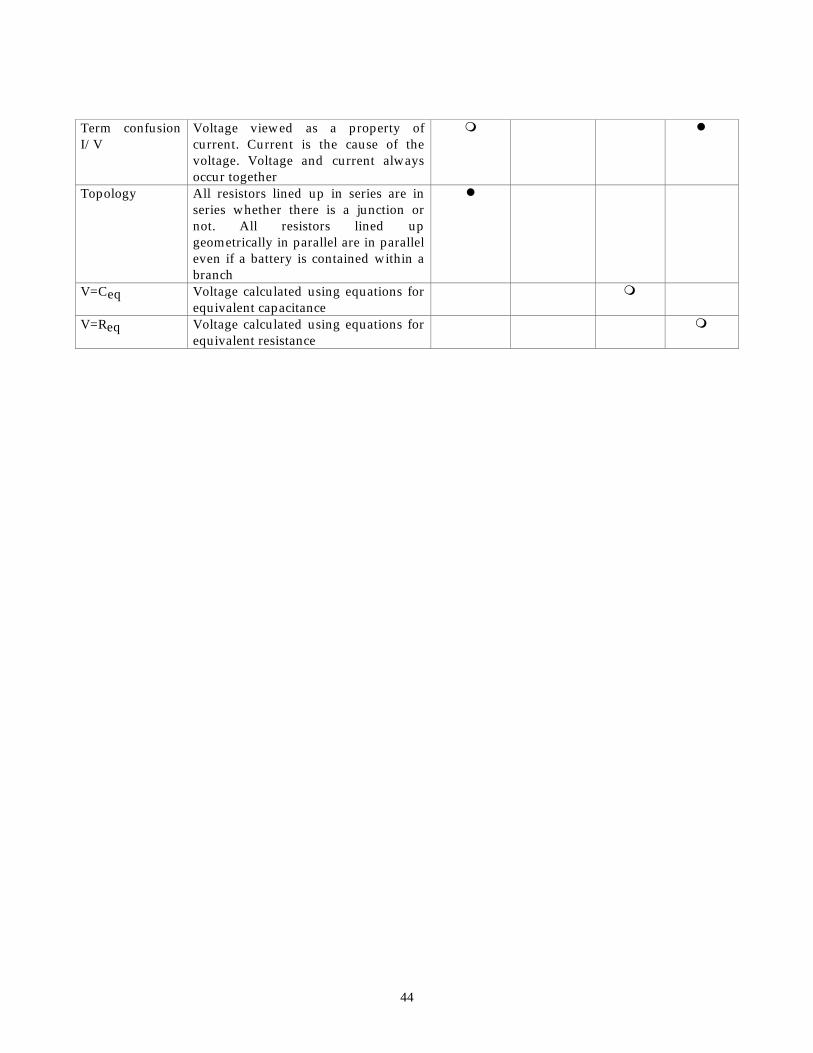
Table V: Misconceptions found during interviews. Solid dots indicate misconceptions used most often. Hollow dots indicate misconceptions used less often.
Description
Physical Aspects Questions
10, 22,23
Current
Questions
8, 20
Energy
Question
3
Voltage
Questions
15, 16, 28, 29
Battery superposition
1 battery — bulb shines x bright 2 batteries, regardless of arrangement — bulb shines 2x bright
m l
Battery as a constant current source
Battery supplies same amount of current to each circuit regardless of the circuit’s arrangement
m l l
Complete circuit Unable to identify a complete circuit — closed loop
m
Contacts Unable to identify the two contacts on the light bulb
l
Current consumed
Current value decreases as you move through circuit elements until you return to the battery where there is no more current left
m l m
Direct route Battery is the only source of charge so only those elements with a direct contact to the battery will light
m
E = 0 inside Electric field inside a conductor is always zero
m
I causes E Current is the cause for the electric field inside the wires of the circuit
l
Local Current splits evenly at every junction regardless of the resistance of each branch
m m l
Req Student equated the equivalent resistance of a circuit with an individual resistor
m m
Resistive superposition
1 resistor reduces the current by x 2 resistors reduce the current by 2x regardless of the resistor’s arrangement
m m
Rule application error
Misapplied a rule governing circuits. For example, used the equation for resistor in series when the circuit showed resistors in parallel
m m
Sequential Only changes before an element will affect that element
m m
Term confusion I/R
Resistance viewed as being caused by the current. A resistor resists the current so a current must flow for there to be any resistance
l
44
Term confusion I/V
Voltage viewed as a property of current. Current is the cause of the voltage. Voltage and current always occur together
m l
Topology All resistors lined up in series are in series whether there is a junction or not. All resistors lined up geometrically in parallel are in parallel even if a battery is contained within a branch
l
V=Ceq Voltage calculated using equations for equivalent capacitance
m
V=Req Voltage calculated using equations for equivalent resistance
m
45
Table VI: t -test results for each sample taking DIRECT version 1.0.
Group
Mean and standard
deviation for Males
Mean and standard
deviation for Females
Degrees
of freedom
t
p -value
Overall 14 ± 4.7 12 ± 3.4 600 8.5 7.4 x 10⁻¹⁷
University 16 ± 5.0 12 ± 3.7 123 5.2 4.6 x 10⁻⁷
High school 13 ± 4.2 11 ± 3.3 425 5.7 1.1 x 10⁻⁸

46
Figure 1: A circuit representing a series-parallel combination of equal resistances.
Figure 2: A circuit representing a parallel-series combination of equal resistances.
Figure 3: Distribution of scores for both versions of DIRECT - overall sample.
Figure 4: Question 7 from DIRECT version 1.1.
47
A
B
C
Fig. 1.
48
Branch 1
Branch 2
Fig. 2.
49
020
4060
8010
012
0
1 3 5 7 9 11 13 15 17 19 21 23 25 27 29
Score
Nu
mb
er o
f S
tud
ents
ob
tain
ing
th
at s
core
Version 1.0 Version 1.1
Fig. 3.
50
Compare the brightness of the bulb in circuit 1 with that in circuit 2. Which bulb is BRIGHTER?
(A) Bulb in circuit 1 because two batteries in series provide less voltage
(B) Bulb in circuit 1 because two batteries in series provide more voltage
(C) Bulb in circuit 2 because two batteries in parallel provide less voltage
(D) Bulb in circuit 2 because two batteries in parallel provide more voltage
(E) Neither, they are the same
Circuit 1
Circuit 2
Fig. 4.