Embed Size (px)
Citation preview

392
Acta Cryst. (1997). D53, 392--405
Structure of Rabbit Muscle Phosphoglucomutase Refined at 2.4 A Resolutiont
YIWEI Liu, WILLIAM J. RAY JR* AND SETHURAMAN BARANIDHARAN
Department of Biological Sciences, Purdue University, West Lafayette, IN 47907, USA. E-mail: wjr@bilbo, bio.purdue.edu
(Received 14 June 1996; accepted 21 Januar 3, 1997)
Abstract Data between 6.0 and 2.4A resolution, collected at 253 K, were used to refine a revised atomic model of muscle phosphoglucomutase: final crystallographic R factor= 16.3% (Rfree = 19.1%); final r.m.s, deviations from ideal bond lengths and angles = 0.018 ]k and 3.2 °, respectively. Features of the protein that were recognized only in the revised model include: the disposition of water molecules within domain-domain interfaces; two ion pairs buried in domain-domain interfaces, one of which is a structural arginine around which the active- site phosphosenne loop is wound; the basic architec- ture of the active-site 'crevice', which is a groove in a 1½-turn helix, open at both ends, that is produced by the interfacing of the four domains; the distorted hexacoordinate ligand sphere of the active-site Mg 2+, where the enzymic phosphate group acts as a bidentate ligand; a pair of arginine residues in domain IV that form part of the enzymic phosphate-binding site (distal subsite) whose disposition in the two monomers of the asymmetric unit is affected unequally by distant crystallographic contacts; structural differences through- out domain IV, produced by these differing contacts, that may mimic solution differences induced by sub- strate binding; large differences in individually refined Debye-Waller thermal factors for corresponding main- chain atoms in monomers (1) and (2), suggesting a dynamic disorder within the crystal that may involve domain-size groups of residues; and a 'nucleophilic elbow' in the active site that resides in a topological environment differing from previous descriptions of this type of structure in other proteins.
1. Abbreviations and notations The following abbreviations are used: Ep and ED, the phospho and dephospho forms of phosphoglucomutase, PGM; Glc- 1-P and Glc-6-P, a-D-glucose- 1-phosphate and D-glucose-6-phosphate, respectively; P-1-Glc-6- P and P-6-Glc-I-P, a-D-glucose 1,6-bisphosphate; in complexes, the right and left phosphates are bound at the proximal and distal binding sites, respectively; PSer, phosphoserine; HEPES, N-2-hydroxyethylpiperazine
t Supported in part by a research grant from the National Institutes of Health (GM08963).
© 1997 International Union of Crystallography Printed in Great Britain - all rights reserved
ethane sulfonate; B value, Debye-Waller thermal factor; (Bmc)r, the average of B values for N, C a and C for residue r.
Major structural elements in protein are identified by a series of three alphanumeric characters. The first, (1) or (2), refers to monomers 1 or 2, and frequently is omitted when the identity of the monomer is unimportant or is clear. [Monomer (1) is the leading monomer within the asymmetric unit as one proceeds clockwise along the 41 screw axis.] The second character, 1-IV, designates the domain, cf. Fig. 3. [The residues at the beginning of domains 1-IV are 1, 189, 303 and 421, respectively (cf Dai, Liu, Ray & Konno, 1992.)] The third character, o~ or /3, designates the type of structure; the fourth, n, specifies the position along the polypeptide chain relative to other structural elements of that type in the repeating motif of domains I-III. Thus, IIoL3 designates the helix that is the third helix from the beginning of the domain II motif that has a countelrpart in domains I and III (see above reference). The major structural elements in domain IV are designated in a similar manner although they have no counterparts in domains I-III. Structural elements in domains I-III that are not part of the repeating motif are identified by a number that specifies the relative position of the element within the overall sequence: Fig. 3 and Table 3. This number, enclosed in braces, also is used as an adjunct for identifying major structural elements of the repeat motifs. Several loops and turns are identified by a letter: see Fig. 3 and Table 3.
2. Introduction Phosphoglucomutase is a relatively large single-chain enzyme (Mr = 61 600) that catalyzes the transfer of the PO3 fragment of a phosphate group between the 1- and 6-0 atoms of glucose. In its stable form, the enzyme contains a dianionic phosphate group esterified with the 'y-hydroxyl group of Ser116; hence, it is referred to as a phospho enzyme, Ep. In the first step of the reaction, the PO3 fragment of the enzymic phosphate group is transferred to the 1-O atom of Glc-6-P to give Glc-1,6-P2 and the dephospho form of the enzyme, ED. In this initial ED.P-6-Glc-1-P complex, the 1- and 6-phosphate groups are bound, respectively, at the proximal or phosphate- transfer subsite and at the distal or phosphate-binding subsite of the enzyme (Ray, Burgner& Post, 1990). This
Acta C~stallographica Section D ISSN 0907-4449 © 1997

YIWEI LIU, WILLIAM J. RAY JR AND SETHURAMAN BARANIDHARAN 393
first bisphosphate complex is converted into a second such complex via an internal rearrangement prior to the second PO3-transfer step that produces the product. In the second complex, ED.P-1-Glc-6-P, the positions of the 1- and 6-phosphate groups are reversed (Ray, Post, Liu & Rhyu, 1993). Because two phosphate groups are involved in the enzymatic reaction, it is necessary to distinguish between the 'phosphate-binding site', which is substantially removed from the active-site metal ion, and the 'phosphate-transfer site', which is contiguous with the bound metal ion and where the PO3 fragment of a phosphate group is transferred between donor/acceptor O atoms.
This is the third paper on the structure of phos- phoglucomutase. In an earlier study at 2.7 Zk resolution (Dai et aI., 1992), the structure in most regions of domains I-III was well defined. The electron-density maps used to construct that model were calculated with the combined phases from two isomorphous derivatives plus anomalous scattering, molecular averaging about a twofold axis and a provisional model. In response to the poor definition of some structural elements in domain IV of the above model, plus other observations out- lined in Appendix 1 of the supplementary material* the structure of that domain subsequently was re-examined using a map with no model phases. This re-examination eventually led to changes in the connectivity of most of the ten structural elements of that domain (see Fig. 1). Later, when it became possible to collect higher resolution data (Ray, Baranidharan & Liu, 1997), the revised model was incorporated into the asymmetric unit as two independent monomers? and refined against that data. After this refinement it became clear that the orientation of domain IV in the two monomers is slightly different relative to the other three three domains. Since domain IV forms one wall of the active-site groove, this different orientation produces small structural dif- ferences between the active sites of monomers (1) and (2). These differences, in turn, give rise to a half-of-the- sites binding pattern in complexes with either glucose bisphosphate or a vanadate-based transition-state analog: >90% occupancy at one site and <10% at the other (S. Baranidharan, W. J. Ray Jr & Y. Liu, unpublished results). The substrate-induced conformational change in solution that increases the rate of the enzyme-catalyzed PO3-transfer process by many orders of magnitude (Ray, Long & Owens, 1976) may be related to these crystal phase differences.
* The deposited supplementary material includes three appendices: 1. Model Building Strategies; 2. On the Molecular Mechanism That lnterconverts Monomers (1) and (2); and 3. The Anatomy of the Tetragonal Phosphoglucomutase Crystal. This section also includes Figs. SS1-SS2, and Tables SSI-SS4. Figs. SS3 and SS4 (color) can be accessed at http://bilbo.bio.purdue.edu/-,~wjr. t Since there is no evidence for dimer formation in solution, and since the 'dimer' thus is characteristic only of the crystal, monomers (1) and (2) might well be referred to as molecules (1) and (2). However, to accord with previous usage, the term monomer is retained.
3. Materials and methods
3.1. Crystals
The (NH4)2SO4 (2.1M) in the mother liquor of nine crystals of the phospho form of PGM, Mg 2+ com- plex (P41212; 174.4 x 174.4 x 101.1 ~), was replaced by 55% PEG 600, containing 10 mM MES buffer, pH 6.5, 1 mM MgCI2 and 0.2mM EDTA. A continuous version of the previous desalting procedure (Ray et al., 1991) was used for this replacement (Ray et al., 1997).
3.2. Diffraction data
Diffraction data were collected using an SDMW (Hamlin) two-chamber area-detector system mounted on a Rigaku AFC-6 four-circle diffractometer powered by a Rigaku rotating-anode X-ray generator. Three different orientations of the various crystals were used to collect approximately 60 ° of data both within and in the neighborhood of a 45 ° wedge of reciprocal space. Other procedures were described previously (Dai et al., 1992). Exceptions were that the temperature was 253 K, the collection time per frame was 90 instead of 60 s, and the 20 values for the two detectors were 17 and 300, with crystal-to-detector distances of 960 and 900 mm, respectively. 600 frames were collected per crystal and the data were processed with a modified version
(a)
(b)
Fig. 1. Topology comparison: the previous model, (a) Dai et al. (1993) and the revised model, (b), of domain IV; A, a strand of a #-sheet; H, an o-helix; F, an antiparallel hairpin turn that acts as a flap.

394 P H O S P H O G L U C O M U T A S E
Tab l e 1. Data collection and processing statistics (given in parentheses)
Detector type SDMW (Hamlin) area detector Intensity integration software XDS Data redundancy 4.1 Rmerg e 5.4 Resolution range 20-2.35 (6-2.4) Number of unique reflections 54817 (49694) Rejection criterion la (same) Completeness for range (%) 84.2 (89.1) Distribution of collected reflections in various shells
Cumulative Resolution Completeness completeness range (A) (%) (%)
5.63-20.00 76.6 76.6 4.49-5.63 97.2 86.7 3.93-4.49 97.6 90.3 3.57-3.93 98.6 92.3 3.31-3.57 92.8 92.4 3.12-3.31 87.4 91.6 2.96-3.12 86.3 90.8 2.83 -2.96 84.7 90.1 2.73-2.83 84.2 89.4 2.63-2.73 81.4 88.7 2.55-2.63 80.4 87.9 2.48-2.55 77.7 87.1 2.41-2.48 75.6 86.2 2.35-2.41 56.8 84.1
o f p r o g r a m XDS ( K a b s c h , 1988), u s i n g a = b = 174.4, c = 101.1 A, and r e s o l u t i o n l imi t o f 2 .4 Zk. D a t a f r o m five d e s a l t e d c rys ta l s (see above ) w e r e c o m b i n e d : m e r g i n g R f a c t o r = 5 .4% (Table 1).
3.3. Model refinement
D o m a i n IV o f the p r e v i o u s m o d e l (Dai et al., 1992) was rebu i l t by u s i n g the o r ig ina l a v e r a g e d M I R m a p , bu t w i t h o u t m o d e l phases . T h e r ev i s ed m o d e l w i th its a l t e red t o p o l o g y (Fig. 1) p lus c h a n g e s in an ac t ive-s i t e l o o p ( r e s idues 2 5 1 - 2 6 1 ) w a s r e f ined u s i n g the p r o g r a m X-PLOR (Br t inger , 1992) w i t h p a r a m e t e r file P A R A M 1 9 . T h e t w o m o n o m e r s in the a s y m m e t r i c un i t w e r e t r ea t ed
as i n d e p e n d e n t un i t s in the final s i m u l a t e d - a n n e a l i n g s tep. C o n v e r g e n c e was iden t i f i ed b y m o n i t o r i n g Rfree (Br f inger , 1993). T h e s e q u e n c e o f o p e r a t i o n s u s e d t o g e t h e r w i th s o m e o f the p a r a m e t e r s e m p l o y e d are c i t ed in Tab le 2.*
* The atomic coordinates for this model plus all X-PLOR files, including the reflection file, have been deposited with the Protein Data Bank, Brookhaven National Laboratory (Reference: 3PMG.5, R3PMG.5SF). Free copies may be obtained through The Managing Ed- itor, International Union of Crystallography, 5 Abbey Square, Chester CH1 2HU, England (Reference: AM0050). The following modifica- tions/exceptions are included in the deposited material: the terms, monomers (1) and (2), used herein, become chain A and chain B in the deposited description; water molecules, labeled as Watl..-herein, are labeled HOH 1. • • in the submitted description, where HOH 1-HOH222 are given as part of chain A and HOH223-HOH494 as part of chain B. The active-site phosphoserine residue, referred to herein as PSer116, is Ser116 in the submitted description; the atoms of the phosphate group are PHSll6P, PHSl1601P, etc.
Tab le 2. Refinement history for the current model
1. Powell energy minimization of the previous model (Dai et al., 1992) after altering topology of domain IV and making other minor modifications manually [all 1122 residues plus polar H atoms included, with net electrostatic charges on the side chains of Asp, Glu, Lys and Arg, plus reflections with F2/~r(F 2) >_ 1 in the resolution range 8-2.7 from a previously described NS data set (Dai et al., 1992) and default values of adjustable parameters in X-PLOR], followed by individual B-factor refinement: initial R factor = 32.7%; final R factor = 23.0%.
2. Simulated annealing of model (no formal charges) against NS data set; TBATH = 2273 K; TIMEstep = 0.5 fs; temperature decrement per step = 0.5 K, followed by Powell energy minimization and B-factor refinement as in 1; repeat of last two steps: final R factor = 19.5%. WA value from option CHECK, throughout.
3. Manual changes in loops and side chains based on a 2Fobs- Fcaic map with model phases.
4. Powell energy minimization and B-factor refinement using the higher resolution (253 K) data set described in the preceding paper (6-2.4/~: Table 2, Ray, Baranidharan & Liu, 1997); simulated annealing, Powell energy minimization, and B-factor refinement as in step 2: final R factor = 23%.
5. Refinement as in step 4, but using TBATH= 3273 K: final R factor = 21%.a (Step 4 was repeated at a higher value of TBATh because two adjustable parameters had been mis-set.)
6. Manual changes in loops and side chains, based on program PROCHECK (Laskowski, MacArthur, Moss & Thornton, 1993) and a 2Fobs - Fcalc map with model phases; manual elimination of substantial conformational differences between side chains in similar environments in monomers (1) and (2), where possible, using superimposed electron- density maps plus energy-minimized or annealed omit maps, or by tracking changes in geometry with increasing importance of the X-ray energy term, by varying the W A factor, or by comparing residue interaction energies in corresponding sections of alternative models after molecular dynamics and Powell energy minimization: final R factor = 19.9%.
7.478 water molecules added in stages (see Experimental), interspersed by Powell energy minimization and B-value refinement.
8. Refinement as in step 5, but using TBATh = 5273 K, TIME = 0.5 fs, NSTEp = 25 cycles, a value for WA provided by option CHECK, after a preliminary simulated annealing under these conditions, 440 kJ mo1-1 , and a positional harmonic restraint of 84 kJ mo1-2 for water molecules and Mg 2+ (no formal charges); Rfree monitored during this step and the subsequent PoweU energy minimization.
9. Addition of 16 symmetry-related internal water molecules.
10. Final Powell energy minimization and B-value refinement monitored by use of the free R factor (BriJnger, 1993) (formal charges on amino- acid side chains, but not Mg2+).
11. Molecular dynamics involving a few isolated regions with un- satisfactory energies or geometrics; final R factor= 16.3%; free R value = 19.1%; r.m.s, deviation of bonds and angles from ideal val- ues = 0.018 ~ and 3.2 °, respectively.
3.4. Location of water molecules
P r o v i s i o n a l p o s i t i o n s for wa t e r m o l e c u l e s w e r e
s e l ec t ed f r o m e l e c t r o n - d e n s e areas in an Fobs-Fca ic m a p w h e r e p e a k e l ec t ron dens i t y >_3or ( e q u i v a l e n t
to o-,~ 1.5 in a 2Fobs -Fca lc map ) . O n l y e l ec t ron - d e n s e r e g i o n s w i th in a shel l 2 . 3 - 5 . 5 ~ f r o m the p r o t e i n w e r e accep ted . S u b s e q u e n t r e f i n e m e n t s teps w i th wa t e r m o l e c u l e s in these pos i t i ons , i n t e r s p e r s e d by e x a m i n a t i o n o f d i f f e r e n c e m a p s , va l i da t ed the p o s i t i o n s o f 400 wa t e r m o l e c u l e s : cu t -o f f cr i ter ia ,

YIWEI LIU, WILLIAM J. RAY JR AND SETHURAMAN BARANIDHARAN 395
two hydrogen-bond donors/acceptors within 3.5 ~ of provisional positions and B _< 60 A 2 (cf. Daopin, Davies, Schlunberger & Grtiter, 1994). After adding the first 400 water molecules, the next iteration produced an additional 60 positions; reducing the donor/acceptor constraint to one produced 18 more. Of the total, 70 were 'internal' (cf. Lee & Richards, 1971). 16 water molecules also were included in internal cavities where density _> 1 a and where water previously had been placed in a symmetry-related cavity: total water molecules added, 494, or about 0.4 water molecules per residue.
3.5. The Mg2÷-binding site
Atoms in the model within 9/~ of the active-site Mg 2+ were subjected to further positional refinement using the Powell energy minimization option of X-PLOR. Several different strategies were used. These will be described elsewhere, together with the electrostatic charges as- signed to the phosphoserine (PSer) residue.
3.6. Other procedures
Most other procedures have been described (Dai et al., 1992); PROCHECK (Laskowski, MacArthur, Moss & Thornton, 1993) was used to assess the quality of the model, HOMOLOGY (Rossmann & Argos, 1975, 1976) to define rotation-translation axes for superimposing corresponding C °~ atoms, and MAPMAN (Kleywegt & Jones, 1994) for analyzing electron-density maps. The programs FRODO (Jones, 1978) and O (Kleywegt & Jones, 1994) were used in conjunction with an Evans and Southerland graphics unit for examining electron-density maps and for model building.
4. Results
Some of the results are presented in the supplemen- tary material that has been deposited with the Protein Data Bank at Brookhaven. This supplementary section includes tables SS1-SS6, Figs. SS1 and SS2, plus two appendices: Model Building Strategies and The Anatomy of the Tetragonal Phosphoglucomutase Crystal (Figs. SS3 and SS4).
4.1. Refinement of the revised model
Refinement of the revised model (cf. Materials and Methods and Fig. 1) against the previous 'NS' data set (see Dai et al., 1992) reduced the crystallographic R factor from the previous value of 22.3 to 19.5% (8.0-2.7/~ data, Table 2). Subsequently, a crystal treat- ment was developed that improved the diffraction pattern of preformed crystals sufficiently that data could be collected and processed to 2.4 ~ resolution (Ray et al., 1997). These data were used for further refinement of the revised model (Table 1). Prior to refinement, the R factor versus the new data was 29%. But the R factor rapidly decreased to 19.9% (6.0-2.4/~ data) during simulated
annealing, and finally to 16.3% after addition of 494 water molecules (see below). During the final simulated annealing, the R f r e e decreased monotonically and sta- bilized at 19.1% when the refinement was terminated: r.m.s, deviation of bond lengths and bond angles from their ideal values, 0.018/~ and 3.2 °, respectively. The coordinates of this model have been deposited with the Protein Data Bank.
4.2. Characteristics of the refined model
A PROCHECK analysis of the refined model (Laskowski et al., 1993) shows that 91% of the residues fall within the 'most favored' regions of a Ramachandran plot: Fig. 2. Three of the five residues within the generously allowed region and the single residue in the disallowed region involve lattice contacts; the other two are active-site residues in a loop with functional significance (see Discussion). Quality assessment in each category tested by PROCHECK is better than the average of 'well refined structures' at 2.4/~ resolution. In seven of the eight categories where quality varies with resolution, the quality rating is equal to that designated as an 'average model' refined at a significantly higher resolution: 1.6--1.7/~. Fig. SS1 is a Luzzati plot for this model: r.m.s, coordinate error ~ 0.25/~. Fig. 3 shows separate ribbon diagrams for each of the four domains of the model. The structural elements are numbered from 1 to 40 beginning with the N terminus; a few critical loops are identified by letter. These numbers and letters, enclosed in braces, are used throughout to specify minor
1 8 0 ~ m, ~,: ~ ~ ~
1 3 5 ~ i . . * "
v 0 . . . . . . . . . . .-2 . . . . -'.-4- . . . . . . . . . . . .
~ - - i
- 1 3 5 ¢,
-180 -135 -90 -45 0 45 90 135 lg0 (°)
Fig. 2. Ramachandran diagram for both molecules in the asymmetric unit according to Laskowski et al. (1993). I, non-glycine residues in the most favored region (crosshatched), additionally allowed region (surrounded by solid line), and generously allowed region (not outlined); t~, single non-glycine residue in disallowed region; A, glycine residues.

396 PHOSPHOGLUCOMUTASE
structural elements of the protein and as adjuncts in specifying the major ones. However, major elements usually are referred to by the code described in §1. The identity of the amino-acid resudies comprising each of elements in Fig. 3 is given in Table 3.
In the revised model, the j3-sheet in domain IV is antiparallel with a 6,1,5,4,3,2 topology (Figs. 1 and 3). The directionality of only one strand in the /3-sheet of domain IV differs from the previous model (Fig. 1). However, the connectivity of most of the loops is different. Two helices, {34) and {39), lie on the face of the sheet opposite the active-site groove (see below) and bridge the two topological gaps where the next strand in the sequence is not adjacent to the preceding strand. The first of these, helix IVo~l {34}, is extensively exposed and rather distorted; the other, helix IVo~2 { 39 ), is crescent shaped with two bends of about 45 ° . Domain IV also contains antiparallel hairpin flaps, F1 and F2; F1 lies across the exterior face of domain IV whereas F2 extends at right angles to the/3-sheet of domain IV and tethers domain IV to domain III. In the revised model, the active site clearly is not a cavity, as was suggested previously. Rather, it is a deep groove, open at both ends, at the center of a helical array (right-handed) involving the four domains. In Fig. 4(a), the surface residues of this groove from each domain are color coded: see Table SS3 for residue identities.
6 '
15 18
. . . . . . . ]
V - - 3 2
Fig. 3. Ribbon diagram showing the various structural elements within the separated domains of monomer (2). The viewing axis is close to the local twofold axis; however, domains II and III are translated downward to the left and downward to the right, respectively. From upper left, reading counterclockwise, the domains are I, II, III, and IV. The numbered structural elements are defined in Table 3. In addition, the following loops are indicated: P, phosphoserine loop (domain I), W and M active-site and metal-binding loops (domain II); S, specificity loop (domain III); A, Ala509 loop, F1 and F2, flaps 1 and 2; and H, loop that is substantially different in the two copies of domain IV.
The distal phosphate-binding subsite can be identified in the new model. It is comprised of two arginine side chains, R502 (in strand IV/34 {37)), and R514 (in strand IV/35 {38}). These lie on the opposite side of the active- site groove from the metal ion. In the desalted crystals used in this study, what appears to be a water molecule, Wat397 [peak height = 5.80-; B = 47 A2, monomer (2)], is close enough to interact with both of these side chains. But in PGM crystals suspended in ammonium sulfate (to be described elsewhere) this position is occupied by an electron-dense group that almost certainly is a sulfate ion. (Sulfate binds to the distal phosphate-binding site of the phospho enzyme competitively with Glc-l-P: Ray & Roscelli, 1966.) When SOl- is inserted into this density, two of its O atoms lie about 2.6Zk from Arg502N ol and Arg514N °1, respectively. This assignment also is in accord with an earlier NMR distance measurement on the methyl phosphonate complex of the Mn 2+ en- zyme: Mn2+-to-methyl proton distance= 10-11 ]k (Ray & Mildvan, 1973). Thus, if one of the unligated O atoms of the sulfate ion is replaced by a methyl group to mimic methyl phosphonate the methyl proton-metal ion distance is in good agreement with the NMR distance assessment.
4.3. The local axis for domains I-III
Fig. 5(c) shows the coordinate differences for C a atoms after least-squares superimposition of monomer (2) onto monomer (1) using a local axis (r.m.s. coordi- nate difference after superposition = 0.27 A). The local axis (matrix a, Table 4) was defined by the C a atoms of 301 'core residues' in domains I-III, i.e., by residues in the sheets and non-exposed helices of the repeat motif (see Dai et al., 1992). (75% of the total were considered as core residues; these are represented by the line segments in Fig. 5c: see also Table 3.) In Fig. 5(c) the first seven 'spikes' show clearly where lattice contacts influence the structure of surface loops. The much larger superposition distances to the right of residue 420 in Fig. 5(c) involve residues of domain IV. The origin of these differences is considered later.
4.4. Differences in Debye-Waller thermal factors between corresponding atoms in monomers (1) and (2)
In the Fig. 5(a) plot of average B values for the main- chain N, C a and C atoms of a given residue, i.e., (Brae)r,
versus residue number, the large peaks identify regions in both monomers where B values are substantially higher than average. All are related to surface features, as is expected (Finzel & Salemme, 1985). In fact, all residues with (Bmc)r = 50/~2, other than those in loop {A}, are among the loosely packed structural elements of the crystal along the external periphery of the 41 helical arrays, as opposed to their internal surfaces (see Appendix 3, The Anatomy of the Tetragonal Phospho-

YIWEI LIU, WILLIAM J. RAY JR AND SETHURAMAN BARANIDHARAN 397
Table 3. Identity of residues comprising the structural elements of monomer (2)
The constituent amino acids of the regular structural elements shown in Fig. 4 are identified on the basis of hydrogen-bonding patterns according to Kabsch & Sander (1983), although an occasional hydrogen bond is included when the calculated hydrogen-bond energy differs from zero by - 1 . 7 ( - 0 . 4 ) instead of - 2 . 1 kJ mo1-1 ( - 0 . 5 kcalmol-1).
Structural Alternative Structural Alternative Structural Alternative element Type* Residues designationt element Type Residues designationt element Type Residues designation'~
1 fl 4-7 (Ifli I ) 16 ot 204-212 (Ilott) 31 ot 390-404 IIIot4 2 /3 20-24 (I/3o) 17 fl 219-222 IIfll 32 ot 408-419 (IIIotf) 3 ot 25-30 (Ioto) 18 ~ 228-236 II~2 33 /3 421-429 IV/31 4 oe 34-45 Iotl 19 13 247-2485 II/32 34 ot 434-449 IV~I
W ex- lp 251-261 5 /3 55-60 1/31 20 ot 269-276 IIot3 F1 ap-tn 457-459 6 ot 66-79 Iot2 21 fl 283-285 IIfl3 463-465
M ex-lp 287-291 7 /3 84-88 1/32 22 /3 294-296 11/34 35 /3 469-472 IV/32 8 ot 95-105 Iot3 23 ot 305-314 IIc~4§ F2 ap-tn 474-476 9 13 109-113 1/33 24 ~ 320-325 (IIIott) 483-485 P ex-lp 114-125
10 /3 125-132 1fl4 25 /3 330-333 111/31¶ 36 /3 489-493 IV/33 11 ot 140-152 I~4 26 ~ 339-345 IIIot2 37 /3 498-504 IVfl4
A hp-tn 506-510 12 /3 155-158 (I/3~2) 27 /3 351-354 111/32 38 /3 511-521 IV/35
H ex-lp 522-529 13 I3 170-174 (1/35) 28 ot 358-366 IIIot3 39a ot 531-536 IVot2a 14 /3 183-188 (1/36) 29 /3 372-375 111/33 39b c~ 536-546 IVot2b
S ex-lp 376-378 39c ot 547-552 IVot2c 15 a 192-201 (Iloto) 30 /3 379-381 IIIf14 40 /3 559-561 IVfl6
* Structural elements are numbered from 1 to 40, beginning at the N terminus. Several important surface loops or turns are assigned letters: ex-lp, extended loop; ap-tn, antiparallel hairpin turn; hp-tn, hairpin turn. Alternative designations enclosed in parenthesis were used previously (Dai et al . , 1992, Fig. 4). t The alternative designation of the structural elements within the repeat motif in domains I-III is given: see supplementary material; in domain IV the alternative designation of the major structural elements is given. :~ This sequence is too short for identification as a/3-strand according to Kabsch & Sander (1983). It is identified as such by analogy with the related motifs in domains I and III where 5, and 4 residues, respectively, are part of the corresponding strand (cf., Dai et al . , 1992). § This element is referred to as IIot4/IIIotl or I I Ia l / I Ia4 when comparing domains, for reasons described in Dai et al. (1992). ¶ This element is referred to as IIIot4/Ilal, or Ilotl/IIIot4 when comparing domains, for reasons described in Dai et al. (1992).
glucomutase Crystal, in the deposited material). Several structural elements where large differences in (Bmc)r
values are observed between corresponding residues in monomers (1) and (2) (cf. Fig. 5b) are described in the second part of Table SS2, together with the average of the (Bmc)r values for the residues comprising these elements. Two of these are surface helices that rest on the exterior face of the domain IV sheet, where the average value of (Bmc)r is 61 versus 23 ~k 2 for helix IVc~l in monomers (1) and (2) and 48 versus 14Zk 2 for helix IVc~2.
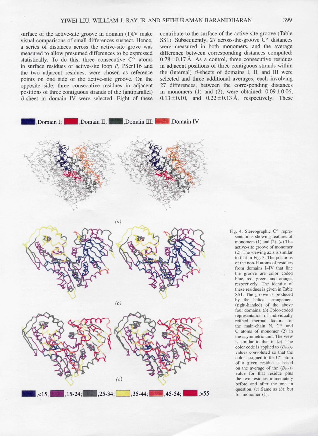
Increased (Bmc)r values in monomer (1) also oc- cur within the core residues of the t3-sheet in domain IV, where average (Bmc)r values are 34 and 12ik 2 in monomers (1) and (2), respectively (Table SS3). In fact, the average (Bmc)r for core residues of domain (1)IV is the largest of the eight domains in the asymmetric unit whereas it is the smallest for domain (2)IV: Table SS3. Figs. 4(b) and 4(c) provide a more qualitative color- coded comparison of (Brnc)r v a l u e s in monomers (1) and (2). Corresponding ( n m c ) r values involving five features of the phosphate-transfer region of the active site plus two adjacent segments of the polypeptide chain that account for the major (Bmc)r difference peak centered
close to residue 265 (Fig. 5b) are described in Table SS2.
4.5. The domain IV problem: conformational differences in the crystal phase that differentially affect the active sites of monomers (1) and (2)
The difference between lattice contacts involving monomers (1) and (2) is the largest in domain IV. Thus, the lateral contacts between the helical arrays of asymmetric units that lie along the 41 axis of the crystal are made exclusively through residues of domain (2)IV. These lateral contacts, which cross a twofold axis, produce a 12-strand sheet from two six-strand sheets of domain (2)IV in adjacent asymmetric units. They also involve two turns each of adjacent o~-helices. These contact differences between monomers (1) and (2) are particularly significant because the domain III-domain IV interface is the most limited of the three domain- domain interfaces and likely the one most readily distorted.
Other differences between monomers (1) and (2) involve an intermolecular contact that bridges one end of the groove between domains I and IV, about 20 from

398 PHOSPHOGLUCOMUTASE
Table 4. Rotation-translation matrices for superimpos- ing core Cot atoms
Matrix a was obtained by using 301 selected Cot atoms from the cores of domains I-HI, monomer (2), and superimposing them upon their counterparts in monomer (1); the core residues used are: 32-46, 53-117, 126-150, 185-211, 218-257, 278-321, 328-343 and 350-418.* Matrix b was obtained similarly by using 33 selected C ot atoms of core residues in domain IV: 421-425; 467-471; 489-500; 512-518; 558-561.t
(0 .2626 -0.9649 0.0087~ (83.5593) a = -0.9641 -0.2628 -0.0388 / 111.2055
0.0398 0.0016 -0.9992 ] 84.6763 ( 0.2437 -0.9697 -0.0185~ ( 84.5267~
b = -0.9671 -0.2415 -0.0794/ 111.0354/ 0.0725 0.0372 -0.9967] 82.4223]
* The r.m.s, superposition .distance for the 301 selected atoms, using a pure rotation axis, is 0.27A; the Eulerian angles, x, ~p, ~0, for this axis are 178.5, 127.4 and 1.12 °, respectively. ~ The r.m.s, superposition distance for the 33 selected atoms, using a pure rotation axis, is 0.26A; the Eulerian angles, (x, ~p, ~p), for this axis are 175.7, 128.0 and 1.25 °, respectively.
the active-site phosphate group. In addition, across one of the local twofold axes that lies nearly perpendicular to the 41 axis, packing constraints force loop {A} in domains (1)IV and (2)IV into non-equivalent interac- tions. These lattice differences produce two secondary effects in addition to the large differences in individu- ally refined Debye-Waller temperature factors between corresponding core atoms of domains (1)IV and (2)IV that were noted above. The two secondary effects, a global difference between the domains I-III/domain IV relationship, and isolated but extensive local conforma- tional differences between domains (1)IV and (2)IV are described below. Since the global difference is assessed in terms of the relationship of core residues in domain IV relative to domains I-III, conclusions about this difference are not substantially affected by the larger atomic B values of peripheral atoms in domain (1)IV. By contrast, local differences are restricted to peripheral segments of the polypeptide chain. Hence, because of the B-value problem, above, identified local differences must be considered only as best estimates.
4.6. Domain IV differences: global
Global differences between the relationship of domain I-III to domain IV in monomers (1) and (2) can be described in terms of non-identical local axes calculated from C a positions (matrices a and b, Table 4). (The r.m.s, superposition distance for both axes is nearly the same, 0.26 and 0.27 A: see also Figs. 5c and 5d.) Because the angle between these axes is small, their intersection is poorly defined. However, the intersection lies well outside the domain III-domain IV interface and some 20/~ from the covalent linkage between domains III and IV. Hence, the interconversion of structures
with core atoms positioned as in monomers (1) and (2) cannot be mimicked by a mechanical hinge-like movement of rigid bodies about a fixed axis. On the other hand, the magnitude of the largest change in C a coordinates required to produce reasonable congruency between monomers (1) and (2) is only about 3 Ik. Spec- ifying the precise mechanism by which these monomers are interconverted thus is difficult. However, one way to produce the required change is to pivot domain (2)IV about an axis well removed from the above covalent link: cf. Appendix 2. On the Molecular Mechanism That Interconverts Monomers (1) and (2) in the deposited material. In solution, larger amplitude movements of this type likely would be restricted by flap F2 in domain IV (cf. Fig. 3).
4.7. Domain IV differences: local
The conformational difference between the Ala509 loop {A } of domains (1)IV and (2)IV produces the high- est spike in the superposition plot of Fig. 5(d) (one point of which is off scale). If the conformation of this loop were the same in both copies of domain IV a substantial overlap between several atoms close to Ala509 would occur within asymmetric units at positions (n) and (n + 4) along the crystallographic 41 axis. This potential overlap also is alleviated by the different relative orientations of domains I-III and domain IV.
In addition to the loop {A } difference, the IVo~ 1 helix { 34 } in monomer (1) appears to be translated by about 0.8 ]k parallel to its axis along the face of the domain IV sheet. If so, this translation would involve only changes in the non-polar interface between the helix and the /3-sheet of domain IV. The number of residues involved in this monomer (1)-monomer (2) difference (arrow a, Fig. 5d) also would be substantially larger than any of the contact-induced differences in domains I-III (Fig. 5c). On the opposite edge of the domain IV sheet, the conformation of loop H also appears to be substantially different in domains (1)IV and (2)IV: arrow H, Fig. 5(d), even though there are no intermolecular contacts involving this loop in either copy of domain IV. Several smaller structural differences between monomers (1) and (2) seem to occur at other peripheral points in domain IV, although none occurs in the central portion of the /3-sheet. Although high B values generate a substantial uncertainty about individual residues involved in the apparent local differences noted here, these differences are based on trends that involve several successive residues.
4.8. Conformational differences between monomers (1) and (2) affect the dimensions of the active-site groove
The global difference between the domains I-III/domain IV relationship appears to narrow the active-site groove slightly in monomer (2). However, high B values for many of the atoms that form the
YIWEI LIU, WILLIAM J. RAY JR AND SETHURAMAN BARANIDHARAN 399
surface of the active-site groove in domain (1)IV make visual comparisons of small differences suspect. Hence, a series of distances across the active-site grove was measured to allow presumed differences to be expressed statistically. To do this, three consecutive C ~ atoms in surface residues of active-site loop P, PSerl l6 and the two adjacent residues, were chosen as reference points on one side of the active-site groove. On the opposite side, three consecutive residues in adjacent positions of three contiguous strands of the (antiparallel) fl-sheet in domain IV were selected. Eight of these
contribute to the surface of the active-site groove (Table SS1). Subsequently, 27 across-the-groove C ~ distances were measured in both monomers, and the average difference between corresponding distances computed: 0.78_+0.17 ]k. As a control, three consecutive residues in adjacent positions of three contiguous strands within the (internal) /3-sheets of domains I, II, and III were selected and three additional averages, each involving 27 differences, between the corresponding distances in monomers (1) and (2), were obtained: 0.09+0.06, 0.13 -+ 0.10, and 0.22 -+ 0.13 ~ , respectively. These
,Domain I; ~ ,Domain 11; ~ ,Domain HI; ~,Domain IV
• ..
• -, ~:~~
~.'~ .~'~ .i..-2 . . . .
, .,,,,. ' .%
(a)
~ , < 15; ~ , 15- 24; ~ , 25-34; [ ] , 35-44; ~ , 45- 54; ,>55
Fig. 4. Stereographic C a repre- sentations showing features of monomers (1) and (2). (a) The active-site groove of monomer (2). The viewing axis is similar to that in Fig. 3. The positions of the non-H atoms of residues from domains I-IV that line the groove are color coded blue, red, green, and orange, respectively. The identity of these residues is given in Table SS1. The groove is produced by the helical arrangement (fight-handed) of the above four domains. (b) Color-coded representation of individually refined thermal factors for the main-chain N, C a and C atoms of monomer (2) in the asymmetric unit. The view is s imi larto that in (a). The color code is applied to (Bmc)r values convoluted so that the color assigned to the C a atom of a given residue is based on the average of the (Bmc)r value for that residue plus the two residues immediately before and after the one in question. (c) Same as (b), but for monomer (1).

400 P H O S P H O G L U C O M U T A S E
operations are illustrated in Fig. 6, where a dashed line connects P S e r l l 6 C ~ to the central C ~ in each group of nine C ~ atoms. A comparison of the four 27-value averages of the corresponding difference between distances shows that even at the current resolution the across-the-groove distance is significantly greater in monomer (1) than in monomer (2), although the groove is narrowed in monomer (2) by less than 1 A. The significance of this difference is given added weight by the observation that the C ~ atoms of Arg502 and Arg514, the most important residues of the phosphate-binding site, are included among the nine selected residues in domain IV. In addition, the across-the-groove difference between the Arg502 CCto- P S e r l l 6 P ~ distances in monomers (1) and (2) is even larger than the difference between the colrresponding C ~ distances: about 1.8 A. However , B values in the range of 55-60 ~k 2 make the latter difference difficult to assess precisely. In any case, it appears that for the substrate to bind in the crystal phase, would require that it fit into a narrower active-site groove in monomer (2) than (1).
4.9. Water molecules
Inclusion of 494 water molecules in the first and second solvation sphere of the protein (B-value cut
off 6 0 ~ 2) reduced the R factor for the model from 19.9 to 16.3%. The B value for 119 of the 494 water molecules was <28 A2, the average B value for the model without water. Of these water molecules, 86 are inaccessible (not including 18 inaccessible water molecules between monomers within the asymmetric unit). The largest group of water molecules, several of which are tetrahedrally coordinated, fills an especially deep crevice at the interface of domains III and IV. Part of this array is shown in Fig. SS2. Additional data on the distribution of hydrogen-bonding partners and B values is given in the supplementary material (Table SS5) together with information on the 26 water molecules where B < 15 ~2, most of which occur in cage-like environments in domain -domain interfaces.
4.10. A completely buried arginine-aspartate ion pair
An interesting structural feature of the present model is a completely buried arginine-aspartate ion pair: Arg63-Asp61. As in most cases where charged residues are buried (Dill, 1990), Arg63 appears to play an important structural role: it forms the core of the active site PSer loop {P}. Thus, three of the five H atoms of the guanidinium group form hydrogen bonds with the carbonyl groups of residues 116, 118 and 125 in loop
v< 50
~Z
o~ ~. 25
A
v
,,~ o
2
2
- - i:: i:: J
(a)
I I , I I 1 I I I I N : :., ; :, :.
w : : : . : : : 7;
R ~ ; i:.~ :...~': ~' ~2 ~ , 4 ~: i.i i:,. ii~.::i i...i
,.?:: ...... :;i , .
" c i i i i i
(b)
o
. . : t n , ~ v ~ ° ~ ~ ®
(c)
'4 F I " c d I F 2 .
(a~ 100 200 300 400 500
Residue number
Fig. 5. Comparisons of monomers (1) and (2): thermal factors for main- chain N, C <~ and C atoms ((Bmc)r) and superposition distances for C a atoms. (a) Average of individually refined atomic B values for the N, C a and C atoms of a given residue in monomers (1) and (2): dotted and solid lines, respectively; symbols showing secondary structure are: ~ , helix; m , strand in a 3-sheet. The numbers below these symbols refer to the structural elements shown in Fig. 3 and defined in Table 3. The dashed line shows the average of the (Bmc)r values for the main-chain atoms of model, 28 A2 which does not differ significantly from the average value for all of the protein atoms (30 Ik2). (b) Difference in (Bmc)r values for corresponding residues viz., monomer (2) minus (1), obtained from values in (a). The following features are labeled: C, intermolecular contact in (1) but not (2) (see yellow region in upper left-hand corner of Fig. 4b); R, the region adjacent to the buried arginine residue; P, the PSer loop; W, the active-site wedge; M, the metal-binding loop; Will, the juncture of domains II and III; 91, 32 and 33,4, the C-terminal edge of the sheet in domains III that is in contact with domain IV; III/IV the juncture of domains III and IV. (c) Superposition distances for C a atoms based on matrix a, Table 3 for domains I-III; positions of the C a atoms of core residues is indicated by the broken solid line. The domain III-domain IV juncture and the center of flap F2 are labeled. (d) Superposition distances for C a atoms of domain IV based on matrix b, Table 3; positions of selected residues indicated broken solid line (see Table 3). The centers of helix IV~ 1, flaps Fl and F2, loops A and H are labeled.

YIWEI LIU, WILLIAM J. RAY JR AND SETHURAMAN BARANIDHARAN 401
{P} (Fig. 7). Hence, this arginine fulfills the criteria suggested for a 'structural' arginine (Borders et al., 1994) without counting its ion-pair interactions with Asp61.
It is noteworthy that Arg63 lies in the domain I-domain II interface, where one face of the guanidinium moiety would be completely exposed to the solvent in the absence of domain II. A similar arrangement exists for a second completely buried acid-base pair, His384-Asp389, which lies in the domain II-domain III interface. If domain II were absent, one face of this pair would be exposed to the solvent. However, it is less certain that the side chains of His384 and Asp389 form an ion-pair as opposed to a hydrogen-bonded pair of formally neutral side chains.
4.11. The phosphoserine loop: {P}
The atom to which a PO3 group becomes attached when the dephospho enzyme reacts with glucose 1,6- bisphosphate is S e r l l 6 O "v. The phosphoserine residue thus formed, PSer l l6 , is part of a 13-residue ~- loop (Leszczynski & Rose, 1988), loop {P}, which lies between strands If33 and I~4 and involves residues 114-126 (Fig. 3). An unusual feature of loop {P} is a non-glycine residue, PSer, which occupies the (i+ 1) position in a type II ~ turn within this loop. The relationship between the ~/~/~ values of this PSer residue and those of the active-site nucleophile in the o~/f4-hydrolases (Ollis et al., 1992) is considered in the Discussion.
5. Discussion
5.1. The revised model
Fig. 1 compares the topology of domain IV in the previous PGM model (Dai et al., 1992) and that de-
scribed herein. The R factor, stereochemistry and other quality assessments of the present model are sufficient to vouch for the absence of the connectivity errors that were present in the previous model.
5.2. Interface water
In contrast to the well packed domain II-III inter- face, which is the least polar of the domain-domain interfaces (Dai et al., 1992) and is devoid of inter- nal water molecules, a series of relatively inaccessi- ble water molecules form an important part of the domain III-domain IV interface (Fig. SS2) as well as a significant fraction of the domain 1-domain II interface. The function of these water molecules is not obvious. However, the number of tfi- and tetrahedrally coordinated water molecules and the regularity of the water network in the domain III/domain IV interface, suggests that this interface has been carefully engineered during the evolution of PGM. In fact, in the latter interface water bridges predominate significantly over direct domain-domain hydrogen bonds. The situation is less clear in monomer (1) due to the higher B values for the atoms of most residues in this monomer, as well as essentially all water molecules.
One obviously cannot reconstruct the normal se- quence of folding steps simply by examining the final structure of a protein molecule. However, if the various domains fold independently of one another, as suggested previously, (Dai et al., 1992), the subsequent formation of domain-domain interfaces would provide a rationale for the large fraction of the internal water molecules that appear in these interfaces. The disposition of the two ion pairs that are buried in these interfaces is also consistent with an independent folding mechanism since in such a case these ion pairs would form first in a surface region.
| l 14 14
Fig. 6. Stereogram showing how differences between distances across the active-site groove in monomers (1) and (2) were assessed. Arrays of nine C a atoms within the/3-sheets of domains I-IV are shown, together with three C a atoms centered at PSer116C ~ in active-site loop P. Dashed lines connect PSer116C ~ to the central C a atom within each array. The number associated with a given line desginates the domain in which the nine-member array is found. The average of the differences between monomers (1) and (2) for each of the 27 corresponding distances between the trio of C a atoms in loop P and the nine C a atoms in a given array are given in Results. The averages of the 27 distances specified by the dashed lines 1-4 in monomer (2) are 15, 19, 21 and 22A, respectively.

402 PHOSPHOGLUCOMUTASE
5.3. Global differences between monomers (1) and (2) within the asymmetric unit
The shape of the PGM monomer is not compatible with efficient packing and the crystals contain approx- imately 61% solvent by volume (Dai et al., 1992). The crystal lattice thus allows for substantial monomer- specific conformational differences between monomers (1) and (2) within the asymmetric unit. And two different local symmetry axes are required to relate domains I-III and domain IV of these monomers because of such differences. The differences are of three types. One involves local difference produced by non-identical crystallographic contacts (cf. spikes in the Fig. 5c plot, including one produced by non-equivalent interactions of loop {A }, domain IV, across a local twofold axis). A more interesting displacement of domain IV relative to domains I-III reduces non-bonded overlaps at the above position (in loop {A })and alters intermolecular contacts at other points. In domain IV, the latter differences give rise to differences in mobility, not only of surface loops but also of core atoms. Thus, the lowest atomic B values for main-chain atoms are calculated for the core of domain (2)IV (12 A2) and the highest for domain (1)IV (34A2: Table SS3). The difference between the relationship of domain IV to domains I-III in these two monomers also narrows the width of the active-site groove in monomer (2) to a small, but significant extent: < 1 A (Fig. 6 and Results). In other words, the distance between the PO3-transfer site in domain I and the phosphate-binding site in domain IV (see Introduction) is reduced in monomer (2). Since the domain movement that would produce a congruency between the structures of these two monomers likely occurs in solution, this
movement may be related to conformational changes induced by substrate binding (Ma & Ray, 1980).
As for the mechanism of the above interconversion, the main-chain residue at the elbow where domain III joins domain IV, Gly420, is relatively unencumbered by packing interactions and seems to be in an ideal position to act as a molecular hinge. However, superpo- sition studies utilizing C a atoms of monomers (1) and (2) (Table 4 and Results) suggest that these differing relationships are produced by a shear-like rather than a hinge-like displacement (Gerstein, Lesk & Chothia, 1994). The movement in question is not dramatic and alters the position of the domain IV residue most distant from the domain III-domain IV interface (Asn524) only by about 3 ~. But its effect on the active-site groove is unmistakable (see above).
5.4. Other differences monomers (1) and (2)
between the active sites of
Four loops, one from each domain, constitute the major elements of the active site of PGM (Dai et al., 1992). These are the phosphoserine loop {P} (domain I), where Serl 16 acts as the donor/acceptor group in the catalytic process; the metal-binding loop, beginning with Asp287 (AspGlyAspGlyAsp: domain II); the specificity loop, where two residues, Glu376 and Ser377, form hydrogen bonds with hydroxyl groups of the glucose ring (S. Baranidharan, Y. Liu & W. J. Ray Jr, unpublished results); and the phosphate-binding site (domain IV), where the phosphate group of Glc-I-P or Glc-6-P, or one of the phosphate groups of Glc-P2 binds.
Activity studies in the crystal phase (Ray, 1986) show that the crystalline enzyme is approximately 20% as
H7 N8
u |
I I
025
H7
\
%
024 ' " "
N8
025
024
Fig. 7. Structure of the active-site loop in domain (2)I showing the interaction of the carbonyl O atoms of this loop with side-chain N atoms of Arg63. Abbreviations are D1, Asp61 C×; R3, Arg63 C ' (atoms of the guanidinium group in red and N atoms marked by +); P, PSer116 pS; H7, Hisl l7 N×, O15, O16, O18, O19, 024, and 025, the carbonyl O atoms of residues Alall5, PSerll6, Asnll8, Prol l9, Gly124, and Asp125; N8, Asnll8 N ~. Terminal main-chain atoms in the four-chain segments not represented by a solid circle are main-chain N and O
atoms.

YIWEI LIU, WILLIAM J. RAY JR AND SETHURAMAN BARANIDHARAN 403
active as in solution under the same conditions. At least part of this difference likely is caused by diffusion within the pores of the crystal. Although both active sites are readily accessible from the same crystal pore (along the 41 axis: Dai et al., 1992), unpublished studies (S. Baranidharan, W. J. Ray Jr & Y. Liu) show that the asymmetric unit exhibits a half-of-the-sites binding pattern with >90% occupancy in monomer (1) and <10% in monomer (2). This behavior is peculiar to the crystal phase since PGM shows no tendency to dimerize in solution under crystal-growth conditions (30mgml-1),
as deduced by quasi-elastic light scattering (W. J. Ray Jr, unpublished results).
Three active-site differences can be discerned that might account for the observed half-of-the-sites bind- ing pattern, in addition to differences in s the width of the active-site groove noted above. These are, a decreased mobility of monomer (2) relative to monomer (1) (Fig. 4); differences in the identity of residues from an adjacent molecule that bridge one end of the active-site groove, although this bridge is situated nearly 20 ~ from PSer116; differences in the distance between
_ ,NS' > R 2
W1
V7
. PI0
I
1
D
N3~,, \..j
W4 '- , , \
\ . D 9 '
W7
. PI0
" "- .w7
7
I, .3.3 < --JL b .3
"" ) D 9 '
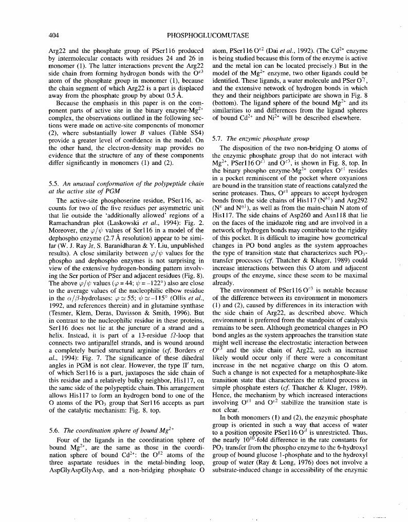
Fig. 8. The disposition of atoms and groups of atoms that interact directly or indirectly with the non-bridging O atoms of the enzymic phosphate group PSer: red. Atoms not covalently bonded to other atoms in the figure are respresented by a cross; hydrogen bonds and metal-ligand bonds are represented by green and orange dashed lines, respectively. Top. Interactions involving P S e r l l 6 0 ~1 and P S e r l l 6 0 ~3. The following abbreviations are used: D2', Asp262 C ~ ; H7, Hisll7 N~; N8', Asnll8 C#; P, PSerll6 P~; P10, Pro261 O; R2, Arg22 Ca; R2', Arg292 C#; SP, PSer116 C a, T4', Thr114 C#; W1 and W9, Wat 481 and Wat419, respectively. The unlabelled atom at the focus of four hydrogen bonds (center) is PSer116 O~1; PSer116 O ~3 is clockwise from PSer1160 E1 and is doubly hydrogen bonded to Arg22 N °l and Arg22 N °2. bottom. Interactions involving PSer116 O n and the active site Mg 2+. The following abbreviations are used: D7', Asp287 C~; D9, Asp289 Ca; D9', Asp389 C~; G8, Gly288 Ca; GO, Gly290 Ca; N3', Asn293 C#; OD1, Asp290 O~1; P10, Pro261 O; P, PSerll6 P~; K8, Lys388 Ca; $4, Ser94 Ca; T5, Thr95 Ca; W1, W3, W4, W7, and W9, Wat271, Wat483, Wat244, and Wat397; Wat329, respectively. The unlabelled crosses that form one and three hydrogen bonds are Wat285 and Thr380N, respectively; the focus of the six coordinate bonds (orange) is Mg 2+.
404 PHOSPHOGLUCOMUTASE
Arg22 and the phosphate group of PSerll6 produced by intermolecular contacts with residues 24 and 26 in monomer (1). The latter interactions prevent the Arg22 side chain from forming hydrogen bonds with the O ~3 atom of the phosphate group in monomer (1), because the chain segment of which Arg22 is a part is displaced away from the phosphate group by about 0.5 A.
Because the emphasis in this paper is on the com- ponent parts of active site in the binary enzyme.Mg 2+ complex, the observations outlined in the following sec- tions were made on active-site components of monomer (2), where substantially lower B values (Table SS4) provide a greater level of confidence in the model. On the other hand, the electron-density map provides no evidence that the structure of any of these components differ significantly in monomers (1) and (2).
5.5. An unusual conformation of the polypeptide chain at the active site of PGM
The active-site phosphoserine residue, PSerll6, ac- counts for two of the five residues per asymmetric unit that lie outside the 'additionally allowed' regions of a Ramachandran plot (Laskowski et al., 1994): Fig. 2. Moreover, the ~/~/~ values of Ser116 in a model of the dephospho enzyme (2.7 ~ resolution) appear to be simi- lar (W. J. Ray Jr, S. Baranidharan & Y. Liu, unpublished results). A close similarity between ~ / ~ values for the phospho and dephospho enzymes is not surprising in view of the extensive hydrogen-bonding pattern involv- ing the Ser portion of PSer and adjacent residues (Fig. 8). The above qo/~/~ values (~ = 44; ~ = -122 °) also are close to the average values of the nucleophilic elbow residue in the o~/fl-hydrolases: ~ _~ 55; ~ ~_ -115 ° (Ollis et al., 1992, and references therein) and in glutamine synthase (Tesmer, Klem, Deras, Davisson & Smith, 1996). But in contrast to the nucleophilic residue in these proteins, Ser116 does not lie at the juncture of a strand and a helix. Instead, it is part of a 13-residue S2-1oop that connects two antiparallel strands, and is wound around a completely buried structural arginine (cf. Borders et al., 1994): Fig. 7. The significance of these dihedral angles in PGM is not clear. However, the type II ~ turn, of which Ser116 is a part, juxtaposes the side chain of this residue and a relatively bulky neighbor, His 117, on the same side of the polypeptide chain. This arrangement allows His117 to form an hydrogen bond to one of the O atoms of the PO3 group that Ser116 accepts as part of the catalytic mechanism: Fig. 8, top.
5.6. The coordination sphere of bound Mg 2+
Four of the ligands in the coordination sphere of bound Mg 2÷, are the same as those in the coordi- nation sphere of bound Cd2+: the O e2 atoms of the three aspartate residues in the metal-binding loop, AspGlyAspGlyAsp, and a non-bridging phosphate O
atom, PSer116 O e2 (Dai et al., 1992). (The Cd 2+ enzyme is being studied because this form of the enzyme is active and the metal ion can be located precisely.) But in the model of the Mg 2+ enzyme, two other ligands could be identified. These ligands, a water molecule and PSer O ~/, and the extensive network of hydrogen bonds in which they and their neighbors participate are shown in Fig. 8 (bottom). The ligand sphere of the bound Mg 2+ and its similarities to and differences from the ligand spheres of bound Cd 2+ and Ni 2+ will be described elsewhere.
5.7. The enzymic phosphate group
The disposition of the two non-bridging O atoms of the enzymic phosphate group that do not interact with Mg 2÷, PSer116 O ~1 and O ~3, is shown in Fig. 8, top. In the binary phospho enzyme.Mg 2÷ complex O ct resides in a pocket reminiscent of the pocket where oxyanions are bound in the transition state of reactions catalyzed the serine proteases. Thus, O ~1 appears to accept hydrogen bonds from the side chains of His117 (N ~l) and Arg292 (N c and Nnl), as well as from the main-chain N atom of His117. The side chains of Asp260 and Asn118 that lie on the faces of the imidazole ring and are involved in a network of hydrogen bonds may contribute to the rigidity of this pocket. It is difficult to imagine how geometrical changes in PO bond angles as the system approaches the type of transition state that characterizes such PO3- transfer processes (cf. Thatcher & Kluger, 1989) could increase interactions between this O atom and adjacent groups of the enzyme, since these seem to be maximal already.
The environment of PSer116 O ~3 is notable because of the difference between its environment in monomers (1) and (2), caused by differences in its interaction with the side chain of Arg22, as described above. Which environment is preferred from the standpoint of catalysis remains to be seen. Although geometrical changes in PO bond angles as the system approaches the transition state might well increase the electrostatic interaction between O ~3 and the side chain of Arg22, such an increase likely would occur only if there were a concomitant increase in the net negative charge on this O atom. Such a change is not expected for a metaphosphate-like transition state that characterizes the related process in simple phosphate esters (cf Thatcher & Kluger, 1989). Hence, the mechanism by which increased interactions involving O ~ and O ~2 stabilize the transition state is not clear.
In both monomers (1) and (2), the enzymic phosphate group is oriented in such a way that access of water to a position opposite PSer116 O ~ is unrestricted. Thus, the nearly 101°-fold difference in the rate constants for PO3 transfer from the phospho enzyme to the 6-hydroxyl group of bound glucose 1-phosphate and to the hydroxyl group of water (Ray & Long, 1976) does not involve a substrate-induced change in accessibility of the enzymic

Y I W E I LIU, W I L L I A M J. R A Y JR A N D S E T H U R A M A N B A R A N I D H A R A N 405
phosphate to the acceptor hydroxyl group. Hence, the mechanism that PGM utilizes to prevent the loss of catalytic potential that would accompany the abortive transfer of the PO3 fragment of the enzymic phosphate group to a water molecule differs from that postulated for several kinases, e.g. hexokinase (Anderson, Zucker & Steitz, 1979).
A consideration of other structure-function relation- ships is deferred pending an evaluation of the proton- transfer steps that accompany the overall PO3-transfer process.
References
Anderson, C. M., Zucker, F. H. & Steitz, T. A. (1979). Science, 204, 375-380.
Borders, C. J. Jr, Broadwater, J. A., Bekeny, P. A., Salmon, J. E., Lee, A. S., Eldrige, A. M. & Pett, V. A. (1994). Protein Sci. 3, 541-548.
Brfinger, A. T. (1992). X-PLOR, Version 3.1, Yale University Press, New Haven, Connecticut, USA.
Brfinger, A. T. (1993). Acta Cryst. D49, 24-36. Dai, J.-B., Liu, Y., Ray, W. J. Jr & Konno, M. (1992). J. Biol.
Chem. 267, 6322-6337. Daopin, S., Davies, D. R. Schlunberger, M. P. & Grater, M.
G. (1994). Acta Cryst. D50, 85-92. Dill, K. (1990). Biochemistry, 29, 7133-7155. Finzel, B. C. & Salemme, F. R. (1985). Nature (London), 315,
686-688. Gerstein, M., Lesk, A. M. & Chothia, C. (1994). Biochemistry,
33, 6739-6749. Jones, T. A. (1978). J. Appl. Cryst. A36, 344-350. Kabsch, W. (1988). J. Appl. Cryst. 21, 916-924. Kabsch, W. & Sander, C. (1983). Biopolymers, 22, 2577-2637.
Kleywegt, G. J. & Jones, T. A. (1994). In From First Map to Final Model, edited by S. Bailey, R. Hubbard & D. Waller, pp. 59-66. Warrington: Daresbury Laboratory.
Laskowski, R. A., MacArthur, M. W., Moss, D. S. & Thornton, J. M. (1993). J. Appl. Cryst. 26, 283-291.
Lee, B. & Richards, F. M. (1971). J. Mol. Biol. 55, 379-400. Leszczynski, J. F. & Rose, G. D. (1988). Science, 234,
849-855. Ma, C. & Ray, W. J. Jr (1980). Biochemistry, 19, 751-759. Ollis, D. L., Chea, E., Cygler, M., Dijkstra, B., Frolow, F.,
Franken, S. M., Harel, M., Remington, S. J., Silman, I., Schrag, J., Sussman, J., Verschueren, K. H. G. & Goldman, A. (1992). Protein Eng. 5, 197-211.
Ray, W. J. Jr (1986). J. Biol. Chem. 261, 275-278. Ray, W. J. Jr, Baranidharan, S. & Liu, Y. (1997). Acta Cryst.
D53, 385-391. Ray, W. J. Jr, Bolin, J. T., Puvathingal, J. M., Minor, W.,
Liu, Y. & Muchmore, S. W. (1991). Biochemistry, 30, 6866-6875.
Ray, W. J. Jr, Burgner, J. W. II & Post, C. B. (1990). Biochemistry, 29, 2770-2778.
Ray, W. J. Jr, Long, J. W. & Owens, J. D. (1976). Biochem- istry, 15, 4006-4017.
Ray, W. J. Jr & Mildvan, A. S. (1973). Biochemistry, 12, 3733-3743.
Ray, W. J. Jr, Post, C. B., Liu, Y. & Rhyu, G. I. (1993). Biochemistry, 32, 48-57.
Ray, W. J. Jr & Roscelli, G. A. (1966). J. Biol. Chem. 241, 2596-2602.
Rossmann, M. G. & Argos, P. (1975). J. Biol. Chem. 250, 7525-7532.
Rossmann, M. G. & Argos, P. (1976). J. Mol. Biol. 105, 75-95. Tesmer, J. J. G., Klem, T. J., Deras, M. S., Davisson, V. J. &
Smith, J. L. (1996). Nature Struct. Biol. 3, 74-86. Thatcher, G. R. & Kluger, R. (1989). Adv. Phys. Org. Chem.
25, 99-263.