Embed Size (px)
Citation preview

Vol. 2, No. 2/February 1985/J. Opt. Soc. Am. A 343
Structure from stereo and motion
Whitman Richards
Natural Computation Group, E10-1.20, Massachusetts Institute of Technology, Cambridge, Massachusetts 02139
Received November 23, 1983; accepted September 5, 1984
Stereopsis and motion parallax are two methods for recovering three-dimensional (3D) shapes. Theoretical analy-ses of each method show that neither alone can recover rigid 3D shapes correctly unless other information, such asperspective and vertical disparity, is included. The solutions for recovering rigid structure from motion have a re-flection ambiguity; the depth scale of the stereoscopic solution will not be known unless the fixation distance isspecified in units of interpupil separation. (Hence the configuration will appear distorted.) However, the correctconfiguration and disposition of a rigid 3D shape can be recovered if stereopsis and motion are integrated, for thena unique solution follows from a set of linear equations. The correct interpretation requires only three points andtwo stereo views.
INTRODUCTION: THE PROBLEM
One of the essential tasks of vision is to determine the three-dimensional (3D) shape of objects in the world.1 Once suchinformation is available, a useful 3D model of an object canbe constructed, which is suitable for recognition or manipu-lation, for example. Unfortunately, neither stereopsis normotion parallax alone provides enough information to recoverthe correct 3D disposition or shape. Each method suffersserious defects unless other information is brought intoplay.
The critical defect with stereopsis is that the same rigidconfiguration of points seen at different distances will elicitdifferent angular disparities on the two retinas. To recoverthe correct distance relations between the points using onlyhorizontal disparity requires knowledge of the fixation dis-tance. 2 Let an observer view an equilateral triangle lying inthe horizontal plane at distance DA as illustrated in Fig. 1(a).If the altitude of the triangle is ZA, then the angular disparity6XA of the nearer point with respect to the farther two basepoints will be
6XA = ZA(I/DA 2 ), (1)
where I is the interpupil separation between the two eyes(cameras) and small angle approximations are taken. Now,if the triangle is moved farther away to position DB, thenclearly the angular disparity 3XB of the near vertex will bereduced by the factor DA 2/DB 2. However, the angular widthof the base will have decreased by only DA/DB. The trianglethat previously appeared equilateral should thus appearsquashed by the factor DA/DB as it is moved farther away.The triangle that appears equilateral based on (horizontal)disparity information alone must thus have a greater altitude,as shown in Fig. 1(b). In sum, the configuration or shape ofa rigid set of points is not uniquely determined from stereopsisalone.
Recovering the 3D configuration from motion also presentsproblems unless information other than the (orthographic)motion of the points is provided. To illustrate the difficulty,let us assume that the motion-parallax solution [or equiva-lently the structure-from-motion (SFM) solution] requiresat least three points and two views [for example, Hoffman and
Flinchbaugh3 and Bobick4 show conditions and constraintsunder which the 3D configuration can be recovered from thetwo-dimensional (2D) projection of three points]; Ullman5
used four points, and Prazdny6 used five points. With oneexception, all these solutions, including those velocity fields,are to a set of second-degree equations, which means thatthere is a duplicate solution that is a reflection about a plane.(More recently, Tsai and Huang7 have obtained a linear so-lution for eight points.) For the given minimum number ofpoints, therefore, each group containing this minimum hasat least two solutions, one being a reflection of the other.Consider then the configuration of six points shown in Fig.2(a). The triplets of points joined by solid lines are in a rigidrelation, but the link between the two groups of triplets is notrigid (dashed line), as if the two parts are joined by a flexiblerod. Because each of the two groups of triplets has a reflectionambiguity, other SFM interpretations of the entire configu-ration are possible, such as the one shown in Fig. 2(b). [Twoother possible interpretations are the reflections of Figs. 2(a)and 2(b) about the horizontal line of four points.] A uniqueSFM solution thus requires removal of the reflection ambi-quity.
By combining stereopsis with SFM we shall see that bothambiguities in the 3D interpretations can be eliminated.Stereopsis provides the sign needed to tell whether the am-biguous points seen with SFM are behind or in front of theothers; SFM, on the other hand, correctly interprets the an-gular relations between the points, thus aiding stereopsis byeliminating the fixation-distance dependency.
STRUCTURE FROM STEREO PROPOSITIONFOR TWO POINTS
Discrete CaseWe will begin by considering the simple discrete case in whicha stereo observer views a rigid configuration of points from oneposition (frame 1) and then moves to another position to ob-tain a second view (frame 2). Thus, although these discreteviews do not make explicit the instantaneous velocities of thepoints, a measure of the relative velocities of the points canbe obtained by keeping the temporal intervals between views
0740-3232/85/020343-07$02.00 © 1985 Optical Society of America
Whitman Richards
344 J. Opt. Soc. Am. A/Vol. 2, No. 2/February 1985
STEREOPSIS DEFECT: SCALE
T1
TDA
L
""
0ZA
I ,
I III I
T
Z
DB
10 /5
(a) (b)
Fig. 1. Two kinds of failings in the recovery of 3D structure. Forstereopsis, a given disparity will indicate a different distance, de-pending upon the observation distance, D. Thus (a) the near vertexof the equilateral triangle at distance DA has the same disparity as(b) the near vertex of the isosceles triangle DB-
either Op, or Zp1. Of course we know xp1 , which appears inthe image, and because the viewing is stereoscopic, we alsoknow the angular disparity of point P1 with respect to O. Letthis disparity be designated as xp1.
Unfortunately, knowledge of the angular disparity of P isnot sufficient to solve for its z coordinate, because by Eq. (1)we do not have knowledge of the interpupil separation or thefixation distance to 0. This was the fatal defect of stereopsisalone. However, if we move our head (or cameras) slightlyto one side, keeping the distance to 0 constant, then we havea second stereo view of P, namely, P2 seen at azimuth xp 2 withthe observed disparity 6xP2. Although this lateral motion hasintroduced a new unknown, namely, ZP2, the ratio ZP1/ZP2 willequal that of the observed disparities 6XP1/6XP2, as can be seenreadily from Eq. (1). Appendix A shows that this informationis then in principle sufficient to recover the distance OP andits orientation to the viewer. Specifically, we can solve for theangle 02 in Fig. 2 as follows:
(b)Fig. 2. When structure is recovered motion, there is a reflectionambiguity. This ambiguity becomes a problem as the structure be-comes increasingly nonrigid, such as when there is a flexible link(dashed line) between two rigid components.
constant. (Below we treat the case for which the instanta-neous velocities are available.) This is the approach used byUllman5 in his classical monocular SFM solution. Theproblem here, then, is to determine how many points P andhow many stereo views V are needed to recover the correctconfiguration of points.
Figure 3 shows the viewing conditions and the coordinatesystem used. The bisector of the lines of sight is taken as theZ axis (note direction); the XZ (horizontal) plane is definedas including the two lines of sight. (The solution will assumethat the horizontal axes of the two retinas or cameras lie in theXZ plane.) The Y axis is normal to the XZ plane at thefixation point 0. The point P(x, y, z) and the origin 0 of thecoordinate systems are assumed to be far away so that per-spective information is nil; hence the projections are ortho-graphic onto the separate frontal planes of the two eyes.
The basic problem is to recover the distance OP(x, y, z) andthe orientation a, r that the ray makes with the Z and Y axes.Because the views are orthographic and epipolar, r appearsin the image plane as does the elevation of P, namely, yp.Because the azimuth of P, namely, xp, also appears in theimage, the problem reduces to recovering r and the distanceOPxz = (Xp 2 + Zp2 )1/2 . Our two unknowns, up and zp, are
thus entirely confined to the horizontal plane. Let us thenconsider only the top view of the situation, as shown in Fig.4.
Here the projection of P(x, y, z) onto the XZ plane is de-noted as P1 for our first point, with the subscript 1 indicatingour first view. The complementary angle 01 = (r/2) - a, hasreplaced a. For any single view and point P, our unknown is
02 = tan- (XP12/XP22- 1)1/21- rp2
(2)
where rp = Xp1/6p 2 . Because OP 2 is simply xp 2 sec 02, wecan calculate OP from yp, which appears in the image plane.Hence we have the following SFM and stereo claim for twopoints:
Claim 1: Given two coplanar orthographic stereo views oftwo rigid points, their correct 3D disposition can be recovereduniquely, independent of fixation distance.
Note that the above claim speaks only of the disposition ofthe two points (i.e., the angle 01). Although we have taken theazimuth xp1 and elevation yp of P to be distances, in fact theyare seen only as angles on the retina. Thus the correct con-figuration, or angular relations between a set of points, can be
Y
z
Fig. 3. Schematic showing theused.
r. X',
I0,P1 ' 0' 0 '
,/' Q.
VIEW 1
coordinate system and notation
XP2 OXq2
zP2:
2 / 2
Zcp2 ,"I 2II
,I,,, U
VIEW 2
Fig. 4. Top view showing the projections of points onto the hori-zontal plane XZ. Note the angle has been replaced by its complement6.
SFM DEFECT: REFLECTION
v--v
(a)
Whitman Richards

Vol. 2, No. 2/February 1985/J. Opt. Soc. Am. A 345
determined uniquely from two stereoscopic views, but not theactual absolute distances.
Continuous CaseOur visual system is remarkably sensitive to directional mo-tion.8 Rather than simply taking snapshots of a configurationof points as we move our heads, let us now assume that theinstantaneous retinal velocity of any point is available, as wellas its position. Under these conditions, Appendix B thenshows that once again the angle 6 may be recovered by usingthe following relation:
(3)
We thus make the following second claim:Claim 2: Given one orthographic stereo view of two rigid
points and their velocities, their correct 3D disposition can berecovered uniquely independent of fixation distance.
Thus we now have two methods of recovering the correctangular relations between a set of points.
THE INTERPRETATION RULE
The above two claims specify the minimal input required inorder to obtain a unique solution for the 3D configuration ofa rigid set of points, as seen in the 2D image. Should we thenapply our solution for the 3D configuration of points to allpairs of points seen on our retinas? Clearly not, for some pairswill not be rigidly linked in three dimensions, and our inter-pretations will be incorrect. We thus need to be able to testfrom the image data whether or not a given pair of points isindeed rigidly linked. Specifically, we are required to identifyfalse targets.
Appendixes A and B analyze the false-target possibility andshow that either one more point or one more (stereo) view willallow the observer to eliminate point pairs that do not arisefrom rigid 3D configurations. Thus we may test and verifyour rigidity hypothesis from the sense data. If the points passthe rigidity test, then we propose that the points be inter-preted as arising from a rigid configurations We then havethe following four interpretation rules:
Rule 1: (Discrete Case): If three coplanar stereo viewsof two points have a fixed separation according to the appli-cation of Eq. (2), then these points should be interpreted asbeing in a rigid configuration.
Rule 2: (Discrete Case): If three points and two coplanarstereo views have a fixed separation according to the appli-cation of Eq. (A2), then these points should be interpreted asbeing in a rigid configuration.
Rule 3: (Continuous Case): If two independent stereoviews of two points plus their velocities suggest a fixed sepa-ration between these points according to Eq. (3), then thesepoints should be interpreted as being in a rigid configura-tion.
Rule 4: If any of the above rules fail to apply (within cer-tain as yet unspecified signal-to-noise considerations), thenthe points are not in a rigid configuration.
SENSITIVITY TO IMPERFECT DATA
The above analysis shows that, in principle, stereo and motioncan be combined to recover the correct 3D configuration of
0=CD
LU
AnUU
LLJL
DISPARITY ERROR, RADIANS
4'
lo-, lo-2 10 l
FRACTIONAL SIZE ERROR
Fig. 5. Effect of noisy image data on the recovery of a 3D configu-ration at 10 m. The ordinate shows the error in estimating a config-uration of two points separated at 1.4 m and oriented at 450 to theobserver in the horizontal plane. (A) Configuration errors introducedby incorrect disparity measurements. (B) Configuration errors in-troduced by incorrect angular-size measurements. The estimationerrors can be reduced substantially if greater lateral movements areused or if the configuration is closer to the observer.
points from 2D-image data. However, what kind of precisionis required of the data in order that the 3D configuration canbe reconstructed with reasonable accuracy? Will only a slightamount of noise in the data cause gross changes in the inter-preted 3D shape, or do the estimation errors increase mono-tonically as the data become increasingly unreliable?
Figure 5 shows the result of one simulation using two stereoviews of two points. (For this analysis, it is not necessary toadd a third view or point.) The test case was two pointsseparated by 1.4 m at 10 m, with one point lying at a 450 or-ientation to the other in the horizontal plane. The interpupildistance was taken as 6.4 cm, and the two stereo views corre-sponded to a 20 movement about the fixation point (i.e., alateral motion of about 0.3 in). Figure 5(A) shows the resultof increasing the disparity-measurement error; Fig. 5(B) showsthe result of increasing the error of the angular-size mea-surements. The crosshatched regions indicate the range ofthe misestimation error, which depends upon whether posi-tive- or negative-measurement errors are introduced. Notethat all estimation errors rise monotonically as the measure-ment errors increase. Hence the interpretation process willbe well behaved under measurement error.
Returning to Fig. 5(A), we see that for the particular con-ditions chosen, a disparity error of 10-5 rad will introduce a70 error in one's estimate of the configuration or orientationof the second to the first point. (The error in estimating the
Whitman Richards
0 = tan-' ( Aj/j 1/2�AWBJ

346 J. Opt. Soc. Am. A/Vol. 2, No. 2/February 1985
separation between points is trivial-less than 10% for mostof the data illustrated.) A disparity error of 10-5 rad corre-sponds to about 2 sec of arc, which is the limit of stereo acuity.An order-of-magnitude improvement in performance occurs,however, if the fixation distance and configuration is reducedto 1 m with the points separated by 14 cm. Alternatively, thelateral movement could be increased. Thus the exquisitehuman stereo sensitivity allows stereo and motion to becombined successfully, especially during locomotion. Figure5(B) shows the effect of introducing errors in the measurementof angular size. Again, because human sensitivity to size 9 isof the order of 3%, the recovery of the 3D structure from the2D-image data seems feasible. Combining both the stereoand size errors does not seriously change these results and mayin fact improve performance when the signs of the two errorsare chosen appropriately.
PSYCHOPHYSICAL PREDICTIONS
The above analysis suggests three possible schemes for re-covering the correct 3D configuration of points using stere-opsis together with motion. To date, no psychophysics isavailable to favor one scheme over another. However, we canpresent some past results showing that stereopsis and motionare indeed intimately coupled modules in the human visualsystem.
Research of Regan and BeverleyIt has long been known that changing an object's size canproduce a compelling impression that the object is moving indepth. 10 The physiological basis for this phenomenon, oftendescribed as looming, which can be seen monocularly, is dif-ferent from motion in depth created binocularly by changingdisparity."1-13 Over the past 10 years, Regan and his col-leagues have amassed considerable evidence for the presenceof separate and quasi-independent channels that each respondselectively either to changing-size stimulation or to chang-ing-disparity stimulation.12,14- 8 Regan's data thus supportthe plausibility of the human visual system's ability to com-pute Eq. (3), for example, which requires measurements ofchanging size or velocity (Ax) and of changing disparity(Abx).
Regan and Beverley' 9 also show that the changing-size andchanging-disparity channels feed into a common motion-in-depth stage. This conclusion is reinforced by more-recentdata of Richards and Liberman,2 0 who explore the nature ofthe interaction. These independent results thus support ourcomputational prediction that both motion and disparityinformation should come together early in the processing inorder that the correct 3D configuration of objects can be de-termined. According to Eq. (3), one possible form of thisinteraction would be a division, or, more simply, a subtractionif a logarithmic transformation of the signals were made enroute to the common stage.
In their 1979 paper, Regan and Beverley' 9 show that the oneadvantage of comparing changing size with changing disparityis that absolute size of the moving object can be recovered upto a constant scale factor, namely, the separation between theeyes. Alternatively, one might view the yardstick for absolutesize as simply the interpupil separation.
In this paper, another role is suggested for a stage thatcombines size change with changing disparity, namely, the
ability to recover the correct configuration of objects in space.To do this, however, requires that the changing size andchanging disparities be measured relative to their currentmagnitudes rather than that the actual increments themselvesbe used as proposed by Regan and Beverley. Thus we useAx/x and Abx/x rather than Ax and A6x.
DemonstrationPerhaps a most convincing argument for the plausibility ofcombining stereo and SFM is a simple demonstration. Ex-amine a tree from your window, or perhaps even your finger-tips arranged in a pentagon and held vertically at arm's length.If you view this tree (or the fingers) with one eye and rock yourhead sideways just a bit, then indeed a 3D shape emerges fromthe motion parallax. Similarly, with binocular viewing andno head motion a 3D shape is also apparent. But are theseimpressions correct? As soon as one combines binocularviewing with the lateral head motion, then the correct 3Dconfiguration becomes clear and vivid.2' Something is clearlygained by combining the two modules.
SUMMARY
Combining stereo disparity with SFM is one way that thecorrect 3D configurations and relations between objects canbe recovered from 2D images. Neither stereopsis nor motionparallax nor SFM can do this alone. That the human visualsystem indeed combines these two computational schemesinto one appears plausible. Not only do our impressions ofthe 3D world improve by the combination, but psychophysicalevidence suggests that the required neural mechanisms arepresent. One immediately is led to inquire whether othermodules in combination, such as stereo and shape fromshading,2 2 or motion and shape from shading, would offersimilar advantages.
APPENDIX A: STRUCTURE FROM STEREOPROPOSITION FOR TWO POINTS
Proposition 1Given two coplanar orthographic stereo views of two rigidpoints, their 3D disposition may be recovered uniquely in-dependent of fixation distance.
ProofLet the two lines of sight from each stereo view lie in the XZplane and intersect at 0, as shown in Fig. 3. Any point P(x,y, z) can then be specified by its distance from 0 and twoangles , r. Because the views are orthographic, r appearsin the image plane, as does the elevation of P, namely, yp andits azimuth x. The problem then reduces to recovering orP,,, the projection of P(x, y, z) onto the XZ plane.
As can be seen from the above remarks, the projection ofP(x, y, z) onto the XZ plane is shown in Fig. 4. For notationalconvenience P, has replaced Pxy and 0 = r/2 - . Our un-knowns are thus Oi and Zpi, because xpi appears in the imageplane.
From the fact that the length OPi is constant over all views,we obtain
Op 1 2 = °p 2 2 = Xp 2 + ZP ,2 = Xp22 + Zp22
with unknowns zpl, Zp2-
(Al)
Whitman Richards
Vol. 2, No. 2/February 1985/J. Opt. Soc. Am. A 347
From the fact that each view is stereoscopic, we obtain thedistance-disparity relation
6Xp = Zpl =rp,6Xp2 Zp2
However, because the disparity ratios for the two views of Pand Q are known, they must also be identical for P and Q toappear the same. Hence from Eq. (A2) we have
(A2)
where xpi is the measured disparity, thereby making rp aknown constant. This relation follows from the fact that thehorizontal disparity of P relative to 0 is given by
bXp = ZP (lID 2) (A3)
Z1= rq = rp =P Zq2 Zp2
Thus, combining Eq. (A7) with Eqs. (A6), we have
Zq_ afzp, Zp ,Zq2 a2 Zp2 Zp2
(A7)
(A8)
where I is the interpupil distance and D is the line-of-sightdistance to 0, and given that the distance OP is much smallerthan D. Taking the ratio of Eq. (3) for i = 1, 2 eliminates the(IID 2 ) dependency.
We now have two equations (Al) and (A2) in two unknowns,Zpl, Zp2 , which can be solved for 02:
02 = tan1 (xP' 2 /xp 22 1)1/2 (A4)
1 -rp2 The length OP2 is then simply xp2 sec 02, from which OP
can be calculated because Yp2 appears in the image plane.
UniquenessThe square root in the solution (A4) for the angle 02 allowsonly positive values for 02. Yet the correct value for 02 maybe either positive or negative, depending on whether point P 2lies in front of or behind the frontal plane containing thefixation point 0. The solution (A4) for 02 is thus not uniqueunless the sign of zp 2 is known. However, the sign of Zp2 is
known. The sign of zp 2 is the same as that for the disparityof P 2, namely, bxp2. Hence the position of P, and thus alsoP(x, y, z) can be determined uniquely.
DegeneraciesUnder some conditions, Eq. (4) cannot be solved for 02. Theonly case is when the denominator (1 - r
2) is zero. This
corresponds to bxpl = bXp2, or when P1 and P2 both lie in thesame frontal plane. [This can be shown to be the only singularcondition by evaluating the Jacobian of Eqs. (Al) and (A2).23
The value of this determinant will be zero only when rp =
zP2 /ZP1. But because rp = Zpl / Zp2 , this singularity corre-sponds to zpl = Zp2 , as before.]
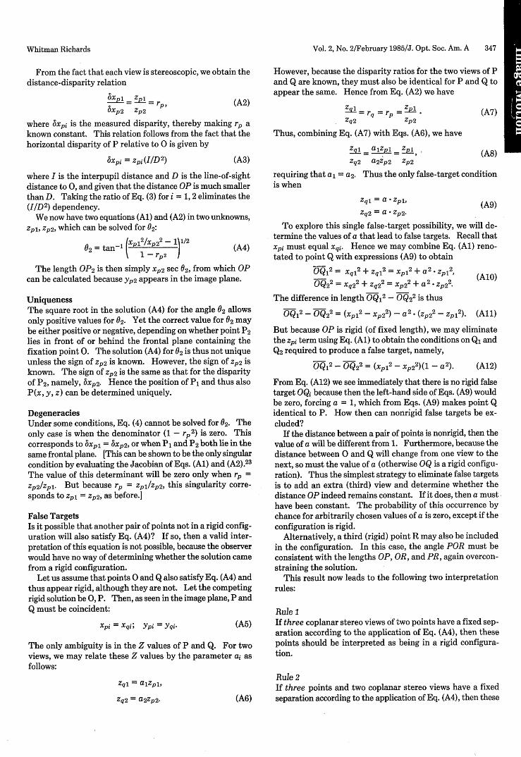
False TargetsIs it possible that another pair of points not in a rigid config-uration will also satisfy Eq. (A4)? If so, then a valid inter-pretation of this equation is not possible, because the observerwould have no way of determining whether the solution camefrom a rigid configuration.
Let us assume that points 0 and Q also satisfy Eq. (A4) andthus appear rigid, although they are not. Let the competingrigid solution be 0, P. Then, as seen in the image plane, P andQ must be coincident:
Xpi = Xqi; Ypi = Yqi- (A5)
The only ambiguity is in the Z values of P and Q. For twoviews, we may relate these Z values by the parameter ai asfollows:
Zq1 alzpl,
Zq2 = a2 Zp2- (A6)
requiring that al = a2. Thus the only false-target conditionis when
Zqi = a zpl,
Zq2 = a Zp2.(A9)
To explore this single false-target possibility, we will de-termine the values of a that lead to false targets. Recall thatXpi must equal Xqi. Hence we may combine Eq. (Al) reno-tated to point Q with expressions (A9) to obtain
OQ1 2 = Xql2 + Zql 2= xP1
2 + a2. zP1
2, (A10)OQ22 = Xq22 + Zq22 =Xp22 + a2 p22 (
The difference in length OQ12- OQ2
2 is thus
OQ12 - OQ22 = ( p 2 - Xp22) - a2 * (Zp22 - ZP1
2). (All)
But because OP is rigid (of fixed length), we may eliminatethe zpi term using Eq. (Al) to obtain the conditions on Q, andQ2 required to produce a false target, namely,
OQ12- OQ22 = (X p 2- xp2 2 )(1 - a2 ). (A12)
From Eq. (A12) we see immediately that there is no rigid falsetarget OQ, because then the left-hand side of Eqs. (A9) wouldbe zero, forcing a = 1, which from Eqs. (A9) makes point Qidentical to P. How then can nonrigid false targets be ex-cluded?
If the distance between a pair of points is nonrigid, then thevalue of a will be different from 1. Furthermore, because thedistance between 0 and Q will change from one view to thenext, so must the value of a (otherwise OQ is a rigid configu-ration). Thus the simplest strategy to eliminate false targetsis to add an extra (third) view and determine whether thedistance OP indeed remains constant. If it does, then a musthave been constant. The probability of this occurrence bychance for arbitrarily chosen values of a is zero, except if theconfiguration is rigid.
Alternatively, a third (rigid) point R may also be includedin the configuration. In this case, the angle POR must beconsistent with the lengths OP, OR, and PR, again overcon-straining the solution.
This result now leads to the following two interpretationrules:
Rule 1
If three coplanar stereo views of two points have a fixed sep-aration according to the application of Eq. (A4), then thesepoints should be interpreted as being in a rigid configura-tion.
Rule 2If three points and two coplanar stereo views have a fixedseparation according to the application of Eq. (A4), then these
Whitman Richards
348 J. Opt. Soc. Am. A/Vol. 2, No. 2/February 1985
points should be interpreted as being in a rigid configura-tion.
APPENDIX B: STRUCTURE FROM STEREOPROPOSITION FOR TWO POINTS PLUSVELOCITIES
Proposition 2Given one orthographic stereo view of two rigid points andtheir velocities, their 3D disposition may be recovereduniquely independent of fixation distance.
ProofOnce again, the relations between the viewer and point P(x,y, z) are as shown before in Fig. 3. Because the projectionsxp and yp are known, the problem reduces to recovering ar orPxz, the projection of P(x, y, z) onto the XZ plane.
From above, the projection of P(x, y, z) onto the XZ planeis shown in Fig. 2 as before, with the substitution 0 = (r/2) -
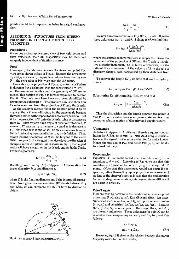
a. Because more details about the geometry of OP are re-quired, this portion of Fig. 4 is further expanded to becomeFig. 6. The notations here have also been simplified bydropping the subscript p. The problem now is to show how0 can be measured from the projection of P onto the X axis.
As the observer rotates about the fixation point 0 by anangle , the XZ axes will rotate by the same angle becausethey are defined with respect to the observer's position. LetR be the projection of P onto the X axis, lying at distance x1from 0. Then for any fixed angle of observer rotation 0, Rmoves to R', causing x1 to increase to x2 and z1 to decrease toZ2. Note that both R and R' will lie on the same arc becauseOP is fixed and zi is perpendicular to xi by definition. Thus,at any instant, the motion of R will be tangent to the circleORP. As 0 - 0, this tangent then describes the direction ofchange R in the XZ plane. As is shown in Fig. 6, the tangentvector will have a length Ax in the X axis and Az in the Z axis.From the geometry,
tan 0 = - . (Bla,b)Az X1
Recalling now from Eq. (A3) of Appendix A the relation be-tween disparity xpl and distance Zpl,
z = x1 (D2/I), (B2)
where D is the fixation distance and I the interpupil separa-tion. Noting that the same relation (B2) holds between Az1and Abxi, we can eliminate the (D2/I) term by division toobtain
Ax 1 AZ1
ox 1 Z1
(B3)
We now have three equations, Eqs. (Bla,b) and (B3), in thethree unknowns Azl, z 1 , and 0. Solving for 0, we find that
=tan-' ( Ax/x 1/2`AAJx)
(B4)
where the expression in parentheses is simply the ratio of theincrement-of the projection of OP onto the X axis to its rela-tive disparity increment. Or, in terms of velocities, it is theratio of the x component of the velocity of P to the rate ofdisparity change, both normalized by their distances from0.
To recover the length 0P1, we note that cos 0 = x0P 1.Hence
OP1 = x1 sec 0 = x,(I + tan 2 6)1/2. (B5)
Substituting Eq. (B4) into Eq. (B5), we find that
OP = ( [1 + /Ax/X 1/2OPJ~~~ex '3x (B6)
Thus the disposition and the length between two points 0and P are recoverable from one dynamic stereo view thatgenerates relative motion of disparity and angular extent.
UniquenessAs before in Appendix A, although there is a square-root so-lution for 0, Eqs. (B4) and (B6) will yield unique solutionsbecause the sign of z is the same as that for Ax and is known.Hence the position of Px, and hence P(x, y, z), can be de-termined uniquely.
DegeneraciesEquation (B5) cannot be solved when x or Abx is zero, corre-sponding to = 7r/2. Referring to Fig. 6, we see that thiscondition is equivalent to point P lying in the sagittal YZplane. (Note that this degeneracy would not occur if per-spective, rather than orthographic projection, were assumed.)As long as the observer's motion is such that the configurationOP will undergo some rotation, this degenerate condition willnot occur in practice.
False TargetsHere we wish to determine the conditions in which a pointother than P will also satisfy Eqs. (B4) and (B6). Let us as-sume that there is such a point Q, with position coordinates(x, y, zq) and velocities (Ax/At, Ay/At, Azq/At). Becausethe x, y, Ax, Ay values appear in the image, the zq and Azqare the only unknowns. These unknowns for point Q can berelated to the corresponding values zp and Azp for point P asfollows:
Zq = alzp,
AZq = a 2AzP.
Fig. 6. An expanded view of a portion of Fig. 4.
(B7)
However, Eq. (B3) gives us the relation between the knowndisparity ratios for points P and Q:
Whitman Richards
Vol. 2, No. 2/February 1985/J. Opt. Soc. Am. A 349
A5xP -ŽRZ6xP
(B8a)zp
AXq - AZq a2 AZP
5Xq Zq alzp
But the disparities Abxp,q and bxpq are observables and hencemust be the same. Equating Eqs. (B8a) and (B8b), we seethat a2 = a. Thus the only false-target condition is when
Azq = aAzp,
Za = azp. (B9)
To explore this single false-target possibility, we will de-
termine the values of a that lead to false targets.Referring to equation (B1), the angular values Op and Oq for
P and Q satisfy
tan O = q =Zp,A~z, x
tan q = AXq = q. (B10)AZq x
ThusxAx = pAzp,
x•Ax = Zq AZq = a2zp Azp, (B11)
where Eqs. (B9) have been used to express the z values for Qin terms of those for P. But Eqs. (B11) force a2
= 1 for all Q's.Hence from Eqs. (B9) we see that Q is identical to P and thereare no false targets. (This result may have been anticipated,because the solution for the configuration of OP was based oninstantaneous values of the position and velocity of P.) Thisresult now leads to the following interpretation rules:
Rule 1
If two independent stereo views of two points plus their ve-locities suggest a fixed separation between these points ac-cording to Eq. (B6), then these points should be interpretedas being in a rigid configuration.
Rule 2If Rule 1 fails to apply (within certain yet-to-be-specifiedsignal-to-noise considerations), then the two points are notin a rigid configuration.
Thus, because Proposition B is based on an instantaneousanalysis of the sensory data, it provides the basis for a po-tentially more powerful scheme for interpreting the structureof both rigid and nonrigid configurations.
ACKNOWLEDGMENT
This report describes research done in the Natural Compu-tation Group at the Department of Psychology, utilizing thefacilities of the Artificial Intelligence Laboratory of theMassachusetts Institute of Technology. Support for thiswork is provided by the National Science Foundation and theU.S. Air Force Office of Scientific Research (AFSOR) undera combined grant for studies in Natural Computation, grant79-23110-MCS, and by the AFOSR under an Image Under-standing contract F49620-83-C-0135.
REFERENCES
1. D. C. Marr, Vision: A Computational Investigation into theHuman Representation and Processing of Visual Information(Freeman, San Francisco, 1982).
2. J. E. W. Mayhew and H. C. Longuet-Higgins, "A computationalmodel of binocular depth perception," Nature 297, 376-378(1982), have shown that, in principle, the use of vertical disparitycan overcome this problem, but the resolution required appearsto be physiologically implausible.
3. D. D. Hoffman and B. E. Flinchbaugh, "The interpretation ofbiological motion," Biol. Cybernet. 42, 195-204 (1982).
4. A. Bobick, "A hybrid approach to structure-from-motion," inProceedings of the ACM Siggraph/Sigart Workshop on Motion(Association for Computing Machinery, New York, 1982), pp.91-109.
5. S. Ullman, The Interpretation of Visual Motion (MIT U. Press,Cambridge, Mass., 1979).
6. K. Prazdny, "Egomotion and relative depth map from opticalflow," Biol. Cybernet. 36, 87-102 (1980).
7. R. Y. Tsai and T. S. Huang, "Uniqueness and estimation ofthree-dimensional motion parameters of rigid objects with curvedsurfaces," Tech. Rep. R-921 (University of Illinois CoordinatedScience Laboratory, Urbana, Ill., 1981).
8. E. Levison and R. Sekuler, "A two-dimensional analysis of di-rection-specific adaptation," Vision Res. 20, 103-107 (1980).
9. C. A. Burbeck and D. Regan, "Independence of orientation andsize in spatial discriminations," J. Opt. Soc. Am. 73, 1691-1694(1983).
10. C. Wheatstone, "Contributions to the physiology of vision," Phil.Trans. B. 13, 371-394 (1838).
11. W. Richards, "Response functions for sine and square-wavemodulations of disparity," J. Opt. Soc. Am. 62, 907-911 (1972).
12. K. I. Beverley and D. Regan, "Evidence for the existence of neuralmechanisms selectively sensitive to the direction of movementin space," J. Physiol. 235, 17-29 (1973).
13. K. I. Beverley and D. Regan, "The relation between discrimina-tion and sensitivity in the perception of motion in depth," J.Physiol. 249, 387-398 (1975).
14. D. Regan and K. I. Beverley, "Looming detectors in the humanvisual pathway," Vision Res. 18, 415-421 (1978).
15. D. Regan and K. I. Beverley, "Visual responses to changing sizeand to sideways motion for different directions of motion indepth: linearization of visual responses," J. Opt. Soc. Am. 70,1289-1296 (1980).
16. M. Cynader and D. Regan, "Neurons in cat parastriate cortexsensitive to the direction of motion in three-dimensional space,"J. Physiol. 274, 549-569 (1978).
17. D. Regan and M. Cynader, "Neurons in cat visual cortex tunedto the direction of motion in depth: effect of stimulus speed,"Invest. Opthalmol. 22, 535-550 (1982).
18. D. Regan, K. I. Beverley, and M. Cynader, "The visual perceptionof motion in depth," Sci. Amer. 241, 136-151 (1978).
19. D. Regan and K. I. Beverley, "Binocular and monocular stimulifor motion in depth: changing disparity and changing size feedthe same motion-in-depth stage," Vision. Res. 19, 1331-1342(1979).
20. W. Richards and H. Lieberman, "A correlation between stereoability and the recovery of structure-from-motion," Am. J.Optom. (to be published).
21. Vertical head motion with stereopsis appears no better than headmotion with monocular viewing.
22. W. E. L. Grimson, "Binocular shading and visual surface recon-struction," A. I. Memo No. 697 (Massachusetts Institute ofTechnology, Cambridge, Mass., 1982).
23. W. A. Richards, J. M. Rubin, and D. D. Hoffman, "Equationcounting and the interpretation of sensory data," Perception 11,557-576 (1982); A. I. Memo No. 614 (Massachusetts Institute ofTechnology, Cambridge, Mass., 1981).
Whitman Richards


![Single View Stereo Matching · 2018-03-12 · passive stereo vision including stereo matching[17,25], structure from motion [35], photometric stereo [5] and depth cue fusion [31],](https://img.pdfslide.us/doc/110x75/5b5e73107f8b9a553d8c92d2/single-view-stereo-matching-2018-03-12-passive-stereo-vision-including-stereo.jpg)