Embed Size (px)
Citation preview
HAL Id: hal-01238551https://hal.archives-ouvertes.fr/hal-01238551
Submitted on 5 Dec 2015
HAL is a multi-disciplinary open accessarchive for the deposit and dissemination of sci-entific research documents, whether they are pub-lished or not. The documents may come fromteaching and research institutions in France orabroad, or from public or private research centers.
L’archive ouverte pluridisciplinaire HAL, estdestinée au dépôt et à la diffusion de documentsscientifiques de niveau recherche, publiés ou non,émanant des établissements d’enseignement et derecherche français ou étrangers, des laboratoirespublics ou privés.
Structure from motion using a hybrid stereo-visionsystem
François Rameau, Désiré Sidibé, Cédric Demonceaux, David Fofi
To cite this version:François Rameau, Désiré Sidibé, Cédric Demonceaux, David Fofi. Structure from motion using ahybrid stereo-vision system. 12th International Conference on Ubiquitous Robots and Ambient Intel-ligence, Oct 2015, Goyang City, South Korea. �hal-01238551�
The 12th International Conference on Ubiquitous Robots and Ambient Intelligence (URAI 2015)October 28 ⇠ 30, 2015 / KINTEX, Goyang city, Korea
Structure from motion using a hybrid stereo-vision systemFrancois Rameau, Desire Sidibe, Cedric Demonceaux, and David Fofi
Universite de Bourgogne, Le2i UMR 5158 CNRS, 12 rue de la fonderie, 71200 Le Creusot, France
Abstract - This paper is dedicated to robotic navigationusing an original hybrid-vision setup combining the ad-vantages offered by two different types of camera. Thiscouple of cameras is composed of one perspective cameraassociated with one fisheye camera. This kind of config-uration, is also known under the name of foveated visionsystem since it is inspired by the human vision systemand allows both a wide field of view and a detail frontview of the scene.Here, we propose a generic and robust approach for SFM,which is compatible with a very broad spectrum of multi-camera vision systems, suitable for perspective and om-nidirectional cameras, with or without overlapping fieldof view.
Keywords - Hybrid vision, SFM
1. Introduction
Binocular vision system is a well-known configura-tion in computer vision which has been studied over thepast decades. This configuration of two similar camerasis widely used for 3D reconstruction, mobile robot nav-igation, etc. Such type of system is particularly inter-esting because it allows the simultaneous capture of twoakin images from which stereo matching can be achievedaccurately using geometrical constraints and photometricdescriptors.In this paper we propose to modify the conventionalstereo-vision system by replacing one of the cameras byan omnidirectional sensor, more specifically a fisheyecamera. This new combination of cameras is very ver-satile as it combines the advantages from both cameras,offering desirable features for robot localisation and map-ping. Indeed, the fisheye camera provides a large visionof the scene. Furthermore, it has been proved in [1] thatspherical sensors are an appropriate solution to overcomethe ambiguities when small amplitude motions are per-formed. On the other hand, the perspective camera canbe employed to extract details from the scene capturedby the sensor. The other advantage offered by this secondcamera is the possibility to estimate the displacements ofa robot at the real scale.In this paper, we propose a novel approach to estimate themotion of a mobile robot using this configuration of cam-eras in an efficient way. This approach is mainly inspiredby non-overlapping SFM techniques.
This article is organized in the following manner. Inthe next section we give a definition of the term hybrid
This work was supported by DGA (Direction Generale de l’Armement)and the regional council of Burgundy.
vision system and review the previous works in 3D recon-struction using hybrid vision system. In the section 3.wedescribe our SFM framework adapted for heterogeneousvision system which does not need inter-camera corre-spondences. While the third part of this paper (section 4.) concerns the results obtained with our method. Finally,a short conclusion ends this article.
2. Previous works
In this section we review the already existing meth-ods developed for the calibration and the navigation usinghybrid-vision system. We are also giving a clear defini-tion about the term ”hybrid-vision system” and their uses.
2.1 Hybrid vision systemThe term of hybrid vision system means that the cam-
eras used within the vision system are of different naturesor modalities [2]. This type of camera association al-lows the acquisition of complementary informations, forinstance, an extension of the field of view, depth informa-tion or the study of a wider range of wavelength.For example, in [3] the authors proposed to merge infor-mation from a conventional binocular system and fromtwo infrared cameras in order to improve pedestrian de-tection process.RGB-D sensors, such as the Kinect, using a reconstruc-tion approach based on the projection of an infra-red pat-tern can also be viewed as hybrid vision sensor. In fact,a RGB camera is used to texture the reconstruction withvisible color, while the infra-red camera can analyse thepattern to reconstruct the 3D structure of the scene. Thesetwo sensors are very complementary. For instance, in [4]the registration of 3D point cloud is simplified by the uti-lization of information from the RGB images. Many oth-ers original combination exist, for example in [5], wherethe sensor consists in the association of a high resolu-tion camera with two low resolution cameras for real timeevents detection.In this article, we are interested in the case where cam-eras have different geometrical properties. More explic-itly, the association of one perspective and one omnidi-rectional camera. This specific type of system has al-ready been studied especially for video-surveillance pur-poses for its ability to obtain conjointly a global view ofthe scene and an accurate image of the target from oneor multiple perspective cameras. The calibration of suchtype of system is discussed in [6] where one omnidirec-tional camera is used in collaboration with a network ofperspective cameras.This configuration of camera can potentially be valuablefor robotic navigation. In [7], the authors propose to usea catadioptric sensor and a perspective camera for obsta-
cle detection. For multi-robot collaboration, Roberti etal. [8] propose an original approach to compute the struc-ture and the motion from multiple robots equipped withdifferent types of camera.Eynard et al. [2] also take advantage of this setup in or-der to estimate both the attitude and the altitude of a UAVusing a dense plane sweeping based registration.
2.2 3D reconstruction and localisation using a hy-brid vision system
Classical structure from motion methods consist in thejoint estimation of the scene structure and the motionfrom a single moving camera [9]. When this type of ap-proach is used to determine the displacements of a robot,the images are sorted temporally. Consequently, they areprocessed one after the other at every new frame acqui-sition, we call this strategy a sequential SFM. The 3Dreconstruction as well as the motion estimation obtainedfrom these methods are up to a scale factor, which repre-sents a limitation in robotic navigation. To overcome thisspecific problem, a common solution is to utilize multi-ple cameras, the most basic example being the conven-tional stereo-vision system (usually two similar perspec-tive cameras). Nevertheless, this sort of configurationneeds a full calibration of the system. Furthermore, anaccurate synchronisation of the cameras is mandatory inorder to ensure a simultaneous images acquisition. Thestereo image matching can be used to estimate the re-construction of the environment with real scale. Mostof the approaches of SFM using stereo-vision systemscan be split into two main steps, the first one being the3D reconstruction of the environment at a time t usingstereo-correspondences only. The second step is the tem-poral tracking of the feature points in the next images.A pose estimation can be performed by minimizing there-projection error of the 3D points on the new imagesacquired at time t+ 1 [10].
Other techniques are also possible. In [11] the authorsproposed a motion estimation using two interlaced tri-focal tensors in order to estimate the six degrees of free-dom of the stereo-rig motion. A more sophisticated waypresented in [12] uses quadrifocal tensor in order to re-cover the motion parameters by dense image registration.These approaches are very efficient as illustrated by theresults obtained with the KITTI dataset [13], howeverthe majority of them concerns perspective cameras only.Only few works focused on visual odometry based ona hybrid stereo vision system. In [2], the displacementof a UAV is evaluated from a hybrid vision system butit is limited to aerial application since the main assump-tion is the planarity of the observed surface (the ground).To the best of our knowledge, no methods have been de-signed for the particular case of calibrated hybrid stereo-vision SFM. The main difficulty arising with these spe-cific types of system equipped with one omnidirectionnalcamera and one perspective camera, is the stereo match-ing between two images of different nature. Multiple arti-cles tackled the problem of hybrid image correspondence,most of the current approaches are based on the adapta-
Mp
o
= [Rp
o
|tpo
]
Mp
o
Oo1
Op1
Op2
Oo2
Mo2
o1
Mp2
p1
Mo3
o1
Mp3
p1
Oo3
Mo3
o2
Mp3
p2
Op3
t+2
t+1
t
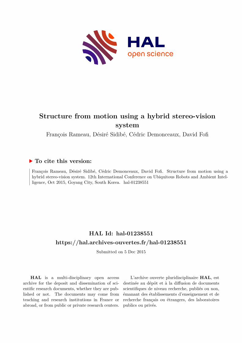
Fig. 1 Model of our system for two successive dis-placements
tion of the usual descriptor to the geometry of the cameras(for instance Harris [14] or SIFT [15]). These descriptorsare often used in conjunction with appropriated geomet-ric constraints in order to remove outliers. The mentionedapproaches can be used to achieve 3D reconstruction ofthe scene and to localize the cameras, however, they donot consider a calibrated stereo-vision system. In fact,this prior calibration is carrying valuable informationswhich can simplify the images matching, for instance,by rectification. Nevertheless, this epipolar rectificationwith cameras having notable different resolutions doesnot allow an accurate matching. Clearly, the inter-cameramatching is a particularly complicated step and needs theuse of sophisticated and computationally expensive ap-proaches. Moreover, the accuracy offered by such typeof process is highly depending upon the dissimilarity be-tween the cameras resolution. Indeed, this difference isemphasized as the focal length of the perspective cameraincreases, making the previously described methods inef-ficient.Nevertheless, the point matching between cameras ofsame nature (omnidirectional or perspective) is a rela-tively basic process since the usual descriptors remainsvery efficient. The proposed method takes advantage ofthis by getting rid of stereoscopic matching using a nonoverlapping field of view SFM method.
3. Methodology
In this paper we propose an adaptation of the non-overlapping SFM method develloped by Clipp et al. [16]to our specific case, that is to say a hybrid vision systemin motion as seen in figure 1. The original method is verysensitive to degenerated motion, so we propose to use anew formulation of the problem based on tri-focal tensorin order to robustify the approach.
3.1 The hybrid stereo-vision system in motionIn this section, we analyse the multi-views relation-
ships of our system. In a first place we consider two
successive displacements of the rig at times t, t + 1 andt+2. Hence, our system is fixed and calibrated, it meansthat the inter-cameras transformation between the fish-eye camera (o) and the perspective camera (p) written
Mp
o
=
✓Rp
o
tpo
0 1
◆is known.
The displacements of the cameras are then linked by thefollowing relations:
Mp
o
Mo2o1(M
p
o
)�1 = Mp2p1 (1)
Mp
o
Mo3o1(M
p
o
)�1 = Mp3p1 (2)
This rigid transformation between our cameras reducedthe number of degrees of freedom to 6 in case of a singlemotion, as it is the case in [16]. This number of DOFrises to 11 for two motions of our vision system, this isthe scenario which is examined in this paper.Despite an overlapping field of view, our approach doesnot consider any stereo correspondences between the twocameras. In other terms, only temporal correspondencesare employed.The only required conditions for our approach are the de-tection of 6 triplet of corresponding points on one cameraand 1 triplet on the other one.Indeed, our approach is essentially based on the fact thatit is possible to estimate the displacement of one camerafrom the computation of a trifocal tensor using 6 tem-poral correspondences [17]. Another minimal solutionfor calibrated cameras has been proposed by Nister andSchaffalitzky in [18], but this approach is less robust andcomputationally more complex. Projection matrices cantherefore be extracted from the mentioned tri-focal tensorusing the approaches described in [17]. Like the essen-tial matrix, this estimation is done up to a scale factor,leaving only a single degree of freedom to estimate. Thiscan be solved with a single matching triplet on the othercamera constituting the vision system. Finally, the min-imal solution needs 7 triplets of points in order to solvethe motion and its scale together. Note that this can eas-ily be extended for multi-camera setup with more thantwo cameras. Furthermore, it is compatible with any SVPcamera thanks to the use of the unified projection model.
3.2 Estimation of the scale factorThe estimation of the two first displacements of the
fisheye camera from the trifocal tensor gives Mo2o1(�) and
Mo3o1(�) where � is a unknown scale factor.
In this section, we describe an approach to retrieve thisscale factor � using only one triplet of correspondingpoints on the perspective camera.The trifocal tensor T 123
p
linking the three perspectiveviews p1, p2 and p3 can be expressed as follow:
T 123p = [T p1, T p2, T p3] (3)
T p1 = Mp2p1[(
2Mp1p1)
T .3Mp1p1 � 3Mp1
p1.2Mp1
p1][⇥](Mp3p1)
T (4)
T p2 = Mp2p1[(
3Mp1p1)
T .1Mp1p1 � 1Mp1
p1.3Mp1
p1][⇥](Mp3p1)
T (5)
T p3 = Mp2p1[(
1Mp1p1)
T .2Mp1p1 � 2Mp1
p1.1Mp1
p1][⇥](Mp3p1)
T (6)
where iM is the i
th line of the matrix M . The relations(1) lead to the following equations, which will be used to
rewrite the perspective camera trifocal tensor only usingthe projection matrices of the omnidirectional camera:
Mp1p1 = Mp
o
, (7)
Mp2p1 = Mp
o
Mo2o1(�), (8)
Mp3p1 = Mp
o
Mo3o1(�). (9)
Then the tensor can be re-written:T123
p
= [Tp1, T
p2, Tp3] (10)
Tp1 = Mp
o
Mo2o1(�)[(2Mp
o
)T .
3Mp
o
� 3Mp
o
.
2Mp
o
][⇥]Mp
o
Mo3o1(�), (11)
Tp2 = Mp
o
Mo2o1(�)[(3Mp
o
)T .
1Mp
o
� 1Mp
o
.
3Mp
o
][⇥]Mp
o
Mo3o1(�), (12)
Tp3 = Mp
o
Mo2o1(�)[(1Mp
o
)T .
2Mp
o
� 2Mp
o
.
1Mp
o
][⇥]Mp
o
Mo3o1(�). (13)
Now, all the entries of the tensor are known, except thescale factor �.The point-point-point (P
p1 �Pp2 �P
p3) transfer func-tion validating this tensor is usually expressed as follow:
Pp2[⇥](
3X
i=1
P i
p1T pi
)Pp3[⇥] = 03⇥3. (14)
The unknown scale factor is embedded in the trifocal ten-sor T
pi
, every single triplet of point provide 9 dependantlinear equations. Only one of these equation can be use tosolve �. Due to the complexity of the resulting equations,we obtained it using a computer algebra system (Matlabsymbolic solver).
3.3 The algorithmIn a first step, the detected points over the three suc-
cessive fisheye and perspective views are projected on theunitary sphere.Thereafter, six triplets of points from the fisheye cameraare used to compute a trifocal tensor. The method used inthis work is the one described in [17]. The robust estima-tion of this tensor is provided by a RANSAC algorithmin order to remove outliers from our data. The reprojec-tion error on the spheres being the criterion used to rejectoutliers in RANSAC.The poses of the fisheye camera can be thereafter ex-tracted from the tensor using methods from [17].At thispoint we have all poses up to a scale factor.
In order to determined the scale factor using only onetriplet of point from the other camera, we used the equa-tion obtained from the point-point-point transfer (14).Once again, a 1 point RANSAC is utilized in order tohave a robust estimation of the scale factor.Once all the poses of our cameras are retrieved, the lin-ear solution obtained can be refined through an ad-hocbundle adjustment process to ensure sufficient accuracy.
4. Results4.1 Synthetic data experimentsTo assess the quality and relevance of our approach
dedicated to poses estimation for not overlapping fieldof view cameras, we propose in this section a series ofsynthetic tests. Our method using the trifocal tensor for-malism is compared to [16], where the author develops a
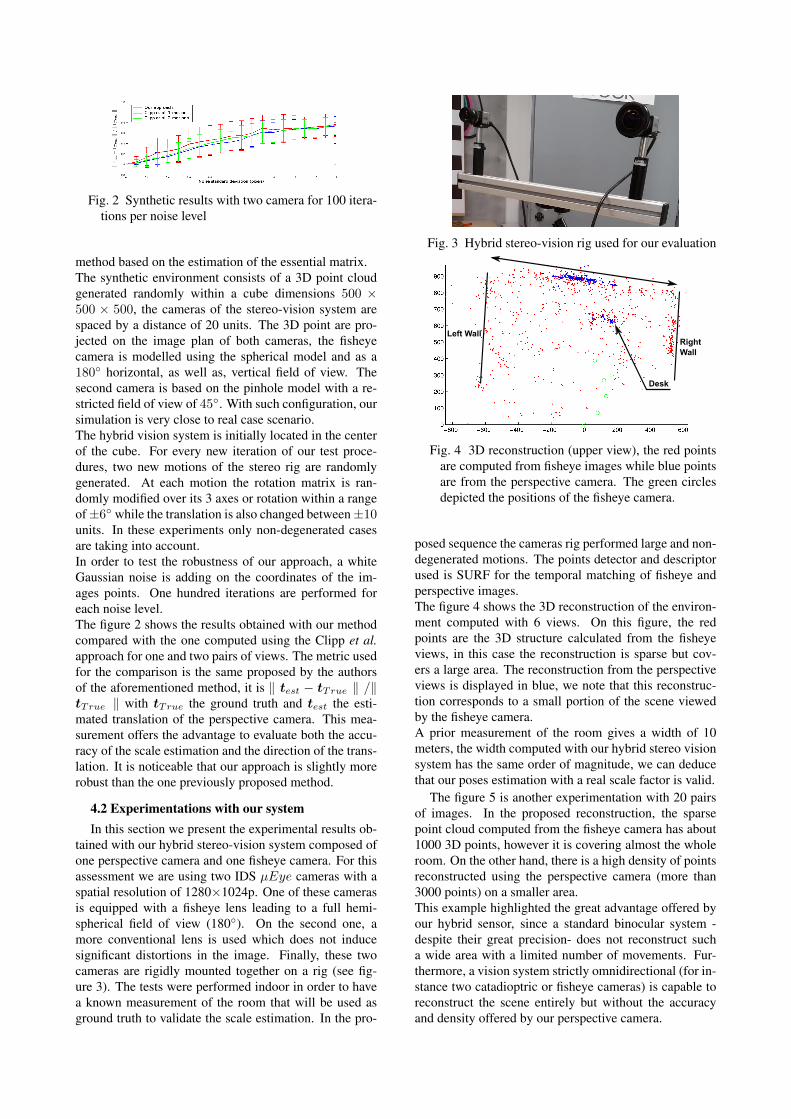
Fig. 2 Synthetic results with two camera for 100 itera-tions per noise level
method based on the estimation of the essential matrix.The synthetic environment consists of a 3D point cloudgenerated randomly within a cube dimensions 500 ⇥500 ⇥ 500, the cameras of the stereo-vision system arespaced by a distance of 20 units. The 3D point are pro-jected on the image plan of both cameras, the fisheyecamera is modelled using the spherical model and as a180� horizontal, as well as, vertical field of view. Thesecond camera is based on the pinhole model with a re-stricted field of view of 45�. With such configuration, oursimulation is very close to real case scenario.The hybrid vision system is initially located in the centerof the cube. For every new iteration of our test proce-dures, two new motions of the stereo rig are randomlygenerated. At each motion the rotation matrix is ran-domly modified over its 3 axes or rotation within a rangeof ±6� while the translation is also changed between ±10units. In these experiments only non-degenerated casesare taking into account.In order to test the robustness of our approach, a whiteGaussian noise is adding on the coordinates of the im-ages points. One hundred iterations are performed foreach noise level.The figure 2 shows the results obtained with our methodcompared with the one computed using the Clipp et al.approach for one and two pairs of views. The metric usedfor the comparison is the same proposed by the authorsof the aforementioned method, it is k t
est
� tTrue
k /ktTrue
k with tTrue
the ground truth and test
the esti-mated translation of the perspective camera. This mea-surement offers the advantage to evaluate both the accu-racy of the scale estimation and the direction of the trans-lation. It is noticeable that our approach is slightly morerobust than the one previously proposed method.
4.2 Experimentations with our systemIn this section we present the experimental results ob-
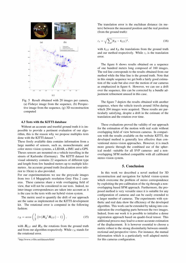
tained with our hybrid stereo-vision system composed ofone perspective camera and one fisheye camera. For thisassessment we are using two IDS µEye cameras with aspatial resolution of 1280⇥1024p. One of these camerasis equipped with a fisheye lens leading to a full hemi-spherical field of view (180�). On the second one, amore conventional lens is used which does not inducesignificant distortions in the image. Finally, these twocameras are rigidly mounted together on a rig (see fig-ure 3). The tests were performed indoor in order to havea known measurement of the room that will be used asground truth to validate the scale estimation. In the pro-
Fig. 3 Hybrid stereo-vision rig used for our evaluation
Left WallRight Wall
Desk
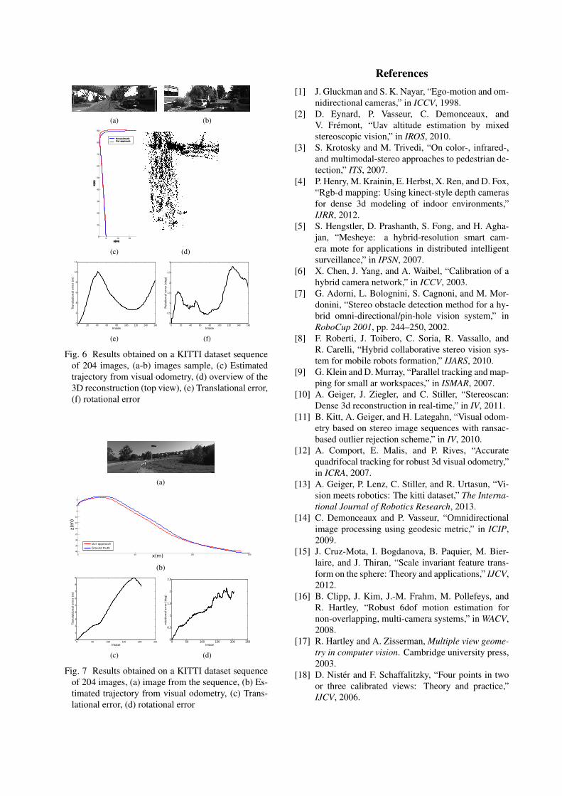
Fig. 4 3D reconstruction (upper view), the red pointsare computed from fisheye images while blue pointsare from the perspective camera. The green circlesdepicted the positions of the fisheye camera.
posed sequence the cameras rig performed large and non-degenerated motions. The points detector and descriptorused is SURF for the temporal matching of fisheye andperspective images.The figure 4 shows the 3D reconstruction of the environ-ment computed with 6 views. On this figure, the redpoints are the 3D structure calculated from the fisheyeviews, in this case the reconstruction is sparse but cov-ers a large area. The reconstruction from the perspectiveviews is displayed in blue, we note that this reconstruc-tion corresponds to a small portion of the scene viewedby the fisheye camera.A prior measurement of the room gives a width of 10meters, the width computed with our hybrid stereo visionsystem has the same order of magnitude, we can deducethat our poses estimation with a real scale factor is valid.
The figure 5 is another experimentation with 20 pairsof images. In the proposed reconstruction, the sparsepoint cloud computed from the fisheye camera has about1000 3D points, however it is covering almost the wholeroom. On the other hand, there is a high density of pointsreconstructed using the perspective camera (more than3000 points) on a smaller area.This example highlighted the great advantage offered byour hybrid sensor, since a standard binocular system -despite their great precision- does not reconstruct sucha wide area with a limited number of movements. Fur-thermore, a vision system strictly omnidirectional (for in-stance two catadioptric or fisheye cameras) is capable toreconstruct the scene entirely but without the accuracyand density offered by our perspective camera.
(a) (b)
−600 −400 −200 0 200 400 600 800
0
200
400
600
800
1000
1200Perspective camera trajectory
Fisheye points
Perspective points
Fisheye camera trajectory
(c)
Fig. 5 Result obtained with 20 images per camera,(a) Fisheye image from the sequence, (b) Perspec-tive image from the sequence, (g) 3D reconstructioncomputed
4.3 Tests with the KITTI databaseWithout an accurate and trustful ground truth it is im-
possible to provide a pertinent evaluation of our algo-rithm, this is the reason why we propose multiples testsdone with the KITTI dataset 1.These freely available data contains information from alarge number of sensors, such as, monochromatic andcolor stereo vision systems, a LIDAR, a IMU and a GPS.Theses sensors are mounted on a vehicle travelling in thestreets of Karlsruhe (Germany). The KITTI dataset forvisual odometry contains 22 sequences of different typeand length from few hundred meters up to multiple kilo-metres. An accurate ground truth (localisation error infe-rior to 10cm) is also provided.For our experimentations we use the greyscale imagesfrom two 1.4 Megapixels resolution Grey Flea 2 cam-eras. These cameras share a wide overlapping field ofview, that will not be considered in our tests. Indeed, nointer-image correspondences are taken into account as itis the case in the tests with our hybrid vision system.
The metric used to quantify the drift of our approachare the same as implemented on the KITTI developmentkit. The rotational error is computed in the followingfashion:
"
R
= acos
✓1
2
�tr(R�1
R
RGT
)� 1�◆
, (15)
with RGT
and RR
the rotations from the ground truthand from our algorithm respectively. While "
R
stands forthe rotational error.
1http://www.cvlibs.net/datasets/kitti/
The translation error is the euclidean distance (in me-ters) between the measured position and the real position(from the ground truth):
"
t
=qX
(tR
� tGT
)2. (16)
with tGT
and tR
the translations from the ground truthand our method respectively. While "
t
is the translationerror.
The figure 6 shows results obtained on a sequenceof one hundred meters long composed of 160 images.The red line corresponds to the results obtained from ourmethod while the blue line is the ground truth. Note thatin this simple sequence we get both a fairly good estima-tion of the scale but also over the motion of our camerasas emphasized in figure 6. However, we can see a driftover the sequence, this can be corrected by a bundle ad-justment refinement unused in this case.
The figure 7 depicts the results obtained with anothersequence, where the vehicle travels around 165m duringwhich 204 images were acquired. These results are par-ticularly satisfying, despite a drift in the estimate of thetranslation and the rotation over time.
These evaluations proved the validity of our approachfor the estimation of the motion with real scale withoutoverlapping field of view between cameras. In compari-son with the results available on the website KITTI, thedeveloped method is generally less effective than con-ventional stereo-vision approaches. However, it is muchmore generic through the combined use of the spher-ical model -suitable for all SVP cameras- and a non-overlapping SFM method compatible with all calibratedstereo-vision system.
5. Conclusion
In this work we described a novel method for 3Dreconstruction and navigation for hybrid vision-systemwhich overcome the problem of stereo correspondenceby exploiting the pre-calibration of the rig through a non-overlapping based SFM approach. Furthermore, the pro-posed method is very versatile since it is suitable for anyconfiguration of cameras and can be easily extended toa larger number of cameras. The experiments with syn-thetic and real data show the efficiency of the developedalgorithm. This work can be extended by taking into con-sideration the overlapping parts between the two images.Indeed, from our work it is possible to initialise a denseregistration approach based on quadri-focal tensor. Thisadditional process may lead to a more accurate estimationof the displacement. It is however essential to choose ametric robust to the strong dissimilarity between omnidi-rectional and perspective views. For instance, the mutualinformation which is a particularly well adapted metricfor this cameras configuration.
(a) (b)
0 10 200
10
20
30
40
50
60
70
80
90
Ground truthOur approach
z(m
)
x(m)
(c) (d)
0 20 40 60 80 100 120 140 1600
2
4
6
8
10
12
Image
Tran
slat
iona
l erro
r (m
)
(e)
0 20 40 60 80 100 120 140 1600
0.5
1
1.5
2
2.5
3
Image
Rota
tiona
l erro
r (de
g)
(f)
Fig. 6 Results obtained on a KITTI dataset sequenceof 204 images, (a-b) images sample, (c) Estimatedtrajectory from visual odometry, (d) overview of the3D reconstruction (top view), (e) Translational error,(f) rotational error
(a)
0 50 100 15040
35
30
25
20
15
10
5
0
5
Our approach
eGround truth
x(m)
z(m
)
(b)
0 50 100 150 200 2500
1
2
3
4
5
6
7
8
9
Image
Tran
slat
iona
l erro
r (m
)
(c)
0 50 100 150 200 2500
0.5
1
1.5
2
2.5
Image
rota
tiona
l erro
r (de
g)
(d)
Fig. 7 Results obtained on a KITTI dataset sequenceof 204 images, (a) image from the sequence, (b) Es-timated trajectory from visual odometry, (c) Trans-lational error, (d) rotational error
References[1] J. Gluckman and S. K. Nayar, “Ego-motion and om-
nidirectional cameras,” in ICCV, 1998.[2] D. Eynard, P. Vasseur, C. Demonceaux, and
V. Fremont, “Uav altitude estimation by mixedstereoscopic vision,” in IROS, 2010.
[3] S. Krotosky and M. Trivedi, “On color-, infrared-,and multimodal-stereo approaches to pedestrian de-tection,” ITS, 2007.
[4] P. Henry, M. Krainin, E. Herbst, X. Ren, and D. Fox,“Rgb-d mapping: Using kinect-style depth camerasfor dense 3d modeling of indoor environments,”IJRR, 2012.
[5] S. Hengstler, D. Prashanth, S. Fong, and H. Agha-jan, “Mesheye: a hybrid-resolution smart cam-era mote for applications in distributed intelligentsurveillance,” in IPSN, 2007.
[6] X. Chen, J. Yang, and A. Waibel, “Calibration of ahybrid camera network,” in ICCV, 2003.
[7] G. Adorni, L. Bolognini, S. Cagnoni, and M. Mor-donini, “Stereo obstacle detection method for a hy-brid omni-directional/pin-hole vision system,” inRoboCup 2001, pp. 244–250, 2002.
[8] F. Roberti, J. Toibero, C. Soria, R. Vassallo, andR. Carelli, “Hybrid collaborative stereo vision sys-tem for mobile robots formation,” IJARS, 2010.
[9] G. Klein and D. Murray, “Parallel tracking and map-ping for small ar workspaces,” in ISMAR, 2007.
[10] A. Geiger, J. Ziegler, and C. Stiller, “Stereoscan:Dense 3d reconstruction in real-time,” in IV, 2011.
[11] B. Kitt, A. Geiger, and H. Lategahn, “Visual odom-etry based on stereo image sequences with ransac-based outlier rejection scheme,” in IV, 2010.
[12] A. Comport, E. Malis, and P. Rives, “Accuratequadrifocal tracking for robust 3d visual odometry,”in ICRA, 2007.
[13] A. Geiger, P. Lenz, C. Stiller, and R. Urtasun, “Vi-sion meets robotics: The kitti dataset,” The Interna-tional Journal of Robotics Research, 2013.
[14] C. Demonceaux and P. Vasseur, “Omnidirectionalimage processing using geodesic metric,” in ICIP,2009.
[15] J. Cruz-Mota, I. Bogdanova, B. Paquier, M. Bier-laire, and J. Thiran, “Scale invariant feature trans-form on the sphere: Theory and applications,” IJCV,2012.
[16] B. Clipp, J. Kim, J.-M. Frahm, M. Pollefeys, andR. Hartley, “Robust 6dof motion estimation fornon-overlapping, multi-camera systems,” in WACV,2008.
[17] R. Hartley and A. Zisserman, Multiple view geome-try in computer vision. Cambridge university press,2003.
[18] D. Nister and F. Schaffalitzky, “Four points in twoor three calibrated views: Theory and practice,”IJCV, 2006.