Embed Size (px)
Citation preview
STRUCTURAL STABILITY OF UDIMET-500, A NICKEL-BASE SUPERALLOY
N. Lambert, J. M. Drapier, J. Collin, and D. Coutsouradisyc
ABSTRACT
The microstructure of Udimet-500 alloy was studied by optical microscopy, transmission electron microscopy, and electron diffraction after different heat treatments. These included short-time aging after different solution treatments and, also, exposure both without stress and under stress for up to 10,000 hours at various temperatures after a three- or four-stage heat treatment
* Respectively:
Research Metallurgist at CNRM Research Metallurgist at CNRM and Assistant at the University of Li'ege Chief Engineer and Head of Laboratories at FN Head of Department at CNRM.
312
STRUCTURAL STABILITY OF UDIMET-500, A NICKEL-BASE SUPERALLOF
INTRODUCTION
Udimet-500 is a wrought nickel-base superalloy extensively used in gas turbines. The use of these engines at increasingly higher temperatures and for longer service requires a more detailed knowledge of the evolution of mechanical properties and, in turn, of microstruc- tures under service conditions. In this study the microstructure of Udimet-500 was investigated by optical microscopy, transmission elec- tron microscopy of replicas or thin foils, and electron diffraction. The heat treatments studied were
(1) Holding at 1175 C or 1050 for various lengths of time and cooling at different rates
(2) Aging at 760 C or 840 C after a ones- or two- stage heat treatment at higher temperatures
(3) Exposure up to 5000 hours at 700-950 C after a three- or four-stage heat treatment
(4) Exposure up to 10,000 hours at 700-1000 C with different stress levels at each temperature after a three- or four-stage heat treatment.
The composition of the 5/8-inch bars of the alloys used in this study is given in Table 1.
Udimet-500 alloy is normally subjected to a three- and four- stage heat treatment. The three-stage heat treatment aims at producing the maximum high-temperature properties in forged material and consists of a solution treatment and a double aging as follows:
Solution treatment: 1080 C for 4 hours and air cooled Aging treatment: 840 C for 24 hours and air cooled Aging treatment: 760 C for 16 hours and air cooled
The four-stage heat treatment is used for bar stock with no subsequent forging. 2 hours at
It involves, prior to the treatments$uoted, an anneal for 1175 C, followed by air cooling.(l)"'
* The part of the investigation carried out at CNRM was sponsored jointly by the Centre d'Information du Cobalt-and the Institut pour 1'Encouragement de la Recherche Scientifique dans 1'Industrie et 1'Agriculture.
*;k References are shown on page 8.
313
PRELIMINARY INVESTIGATION ON HEAT-TREATING CONDITIONS
Solution Treatment
As pointed out above, the industrial heat treatment of Udimet-500 is rather complex and involves three or four stages. The preliminary investigation was carried out to gain a better understand- ing of the effect of heat-treating conditions on grain size and on the nature and distribution of precipitated phases.
Holding for 4 hours at temperatures from 850 to 1200 C followed by a water quench showed that the original ASTM 8 grain size remained unaffected to 1000 C. At 1100 and 1200 C the grain size in- creased considerably to ASTM 2 and ASTM 1, respectively. The initial x1 particle size of about 500 A increased to 3000-4000 A at 1000 C.
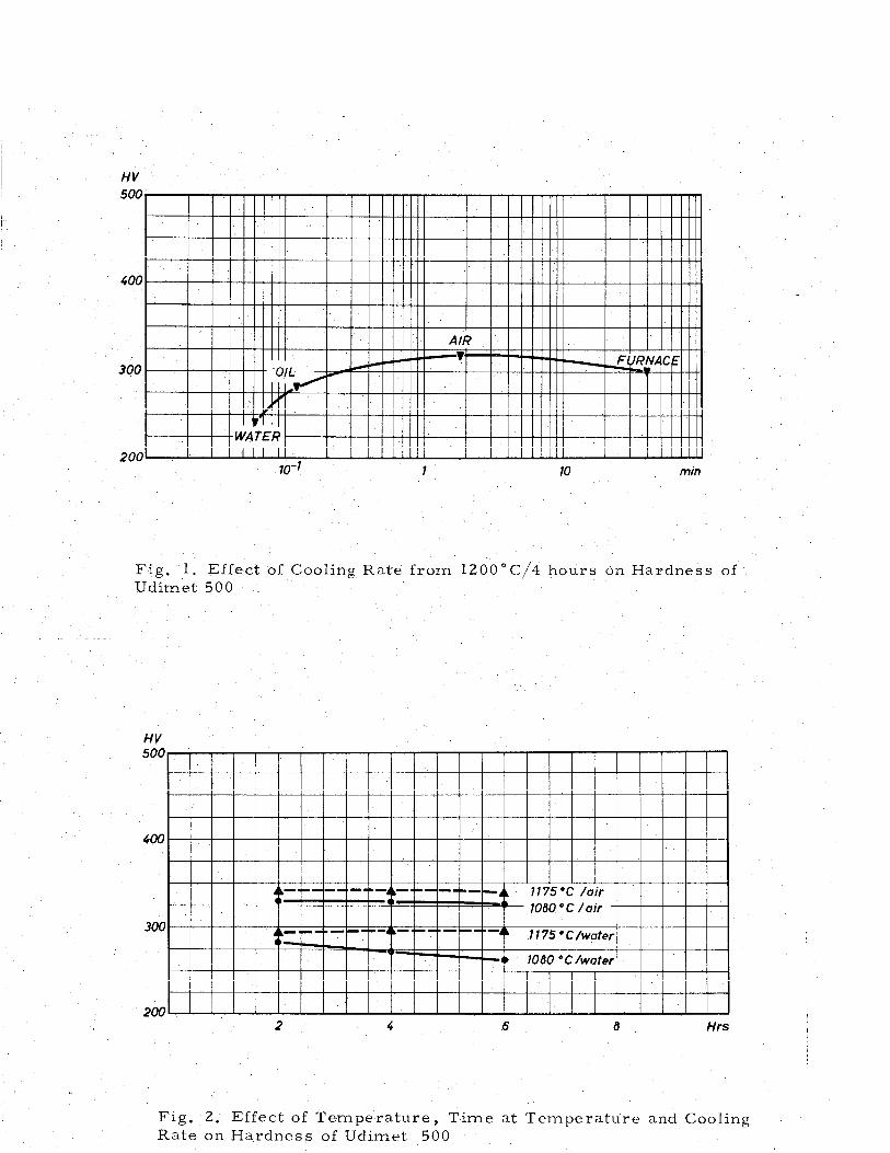
At 1100 C and above, thex' precipitate went into solution. The effect of cooling rate on hardness after holding for 4 hours at 1200 C is shown in Figure 1. cooling,
Because of the rapid.precipitation ofr' during the hardness increased as the cooling rate decreased. Furnace
cooling resulted in a coalescence of the decrease in hardness.
,j@' particles and, hence, in a
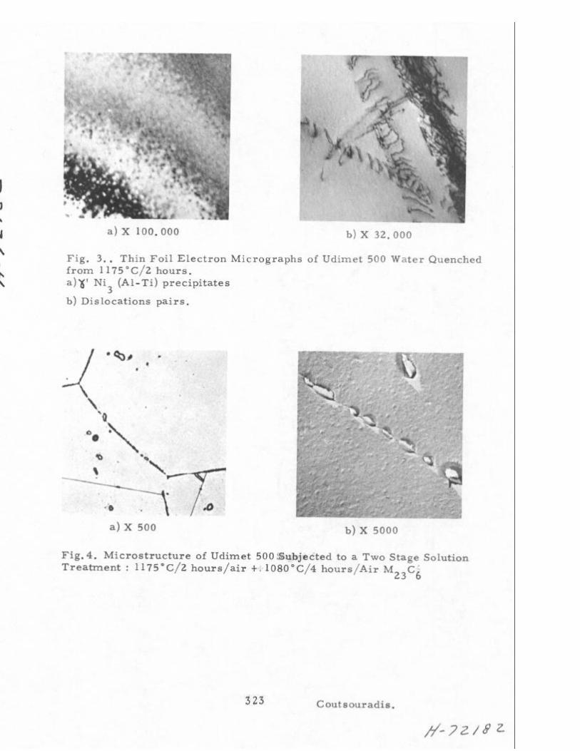
The effect of temperature, time at temperature, and cooling rate on the hardness of Udimet-500 is shown in Figure 2. Hardness increases with increasing temperature or decreasing cooling rate, and remains unaffected with time at 1175 C. The higher hardness obtained after treatment at 1175 C is explained by the fact that, at this tern- perature, MC-type carbides go progressively into solution and, thus, more titanium is available for precipitation during cooling. The rapid precipitation of 8' during cooling is illustrated in Figure 3 for specimens water quenched from 1175 C. The & ' particles are coherent and about 40 A in diameter. The presence of the ordered& ' particles is also demonstrated by the occurrence of dislocation pairs, as shown in Figure 3b, and of superlattice spots 'on electron-diffraction diagrams. After air cooling from 1175 C the #' particle size is about 500 A. Examination of the water-quenched specimen shows that no M23C6- type carbides are present. In air-cooled specimens, such carbides were identified to be in epitaxy relative to the fee matrix.
For specimens heat treated for 4 hours at 1080 C, the same relationships are generally valid as for those treated at 1175 C. As stated above, the grain size is appreciably smaller after the lower solution temperature: ASTM 4-5 instead of ASTM 2-3. The Y' particles are about 50 A in diameter after water quenching and about 300-650 A after air cooling. Because of the small grain size, 'boundary networks of carbides have not been observed.
314
. Specimens subjected successively to 2 hours at 1175 C/air and 4 hours at 108O,C/air shows a microstructure similar to that ob- tained after the single treatment at 1175 C except that discontinuous carbide networks are present at the grain boundaries. (Figure 4). The carbides have precipitated at grain boundaries from the saturated solid solution which resulted from the 1175 C treatment during cooling - and during the 1080 C treatment. The
Y ' size is 300-600 A.
Aging
In the aging experiments, specimens were aged for up to 64 hours after three different solution treatments: 1175 C/2 hr/air 1080 C/4 hr/air, and 1175 C/2 hr/air + 1080 C/4 hr/air.
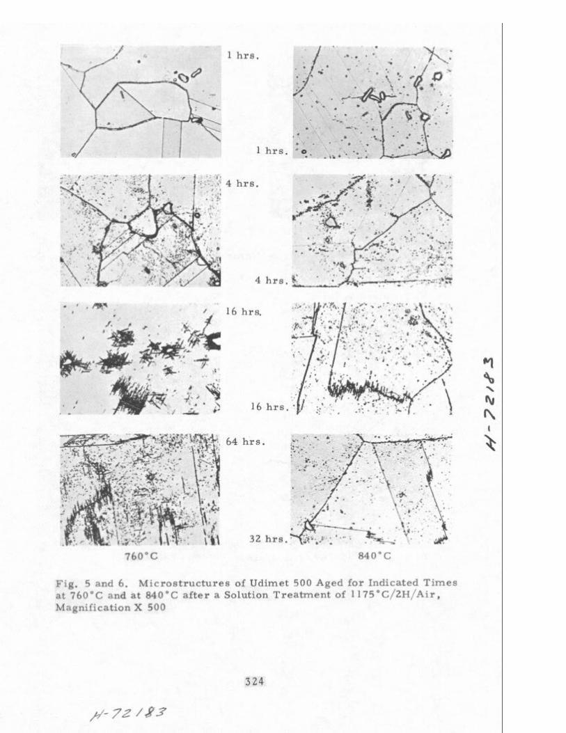
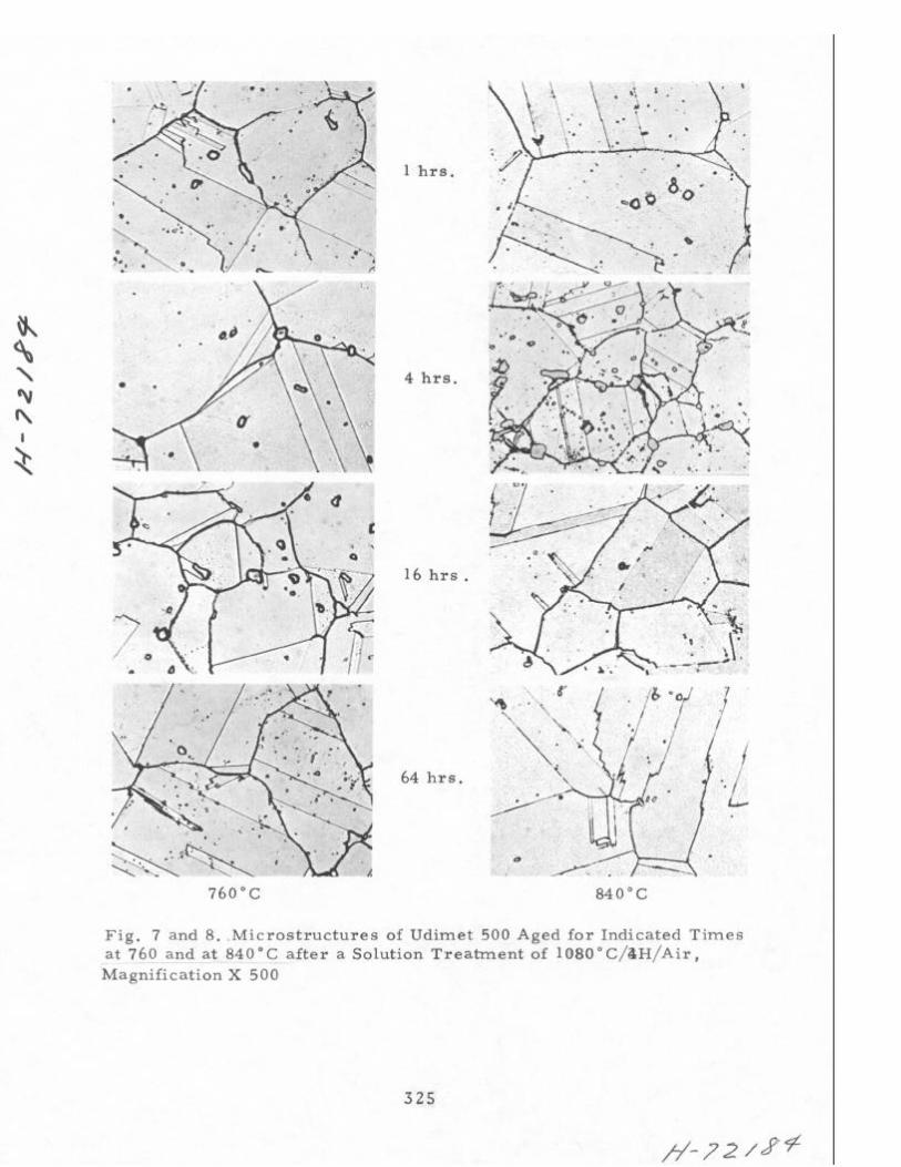
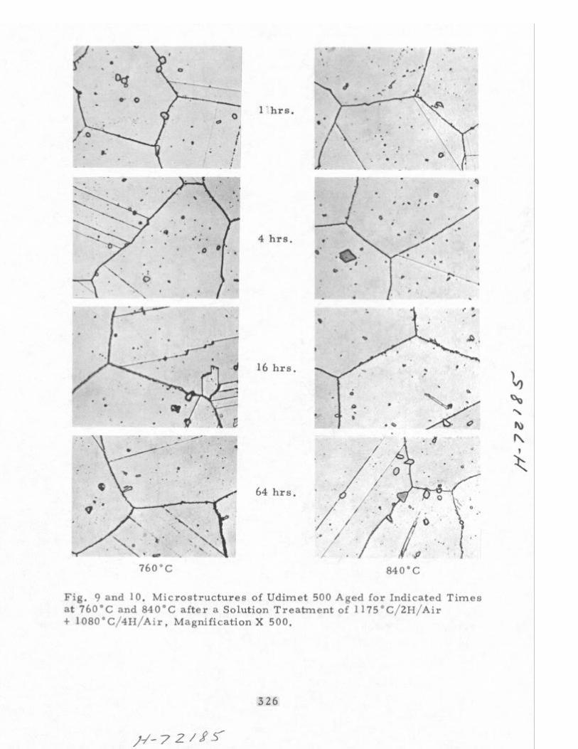
Figures 5 to 10 reproduce the corresponding optical micro- graphs. Examination of these micrographs shows that the solution treatment at 1175 C results,on holding both at 760 and 840 C, in the heterogeneous precipitation of carbides at preferred areas: grain or twin boundaries, massive MC-type carbides, etc. (Figures 5 and 6). Specimens subjected to a treatment at 1080 C do not exhibit this behavior. In this case, the carbides precipitate mainly at the grain boundaries. Specimens subjected to the industrial three- or four-stage heat treatment show a similar behavior. The heterogeneous precipitates of carbides after the treatment at 1175 C result, pre- sumably, in unsatisfactory mechanical and oxidation properties.
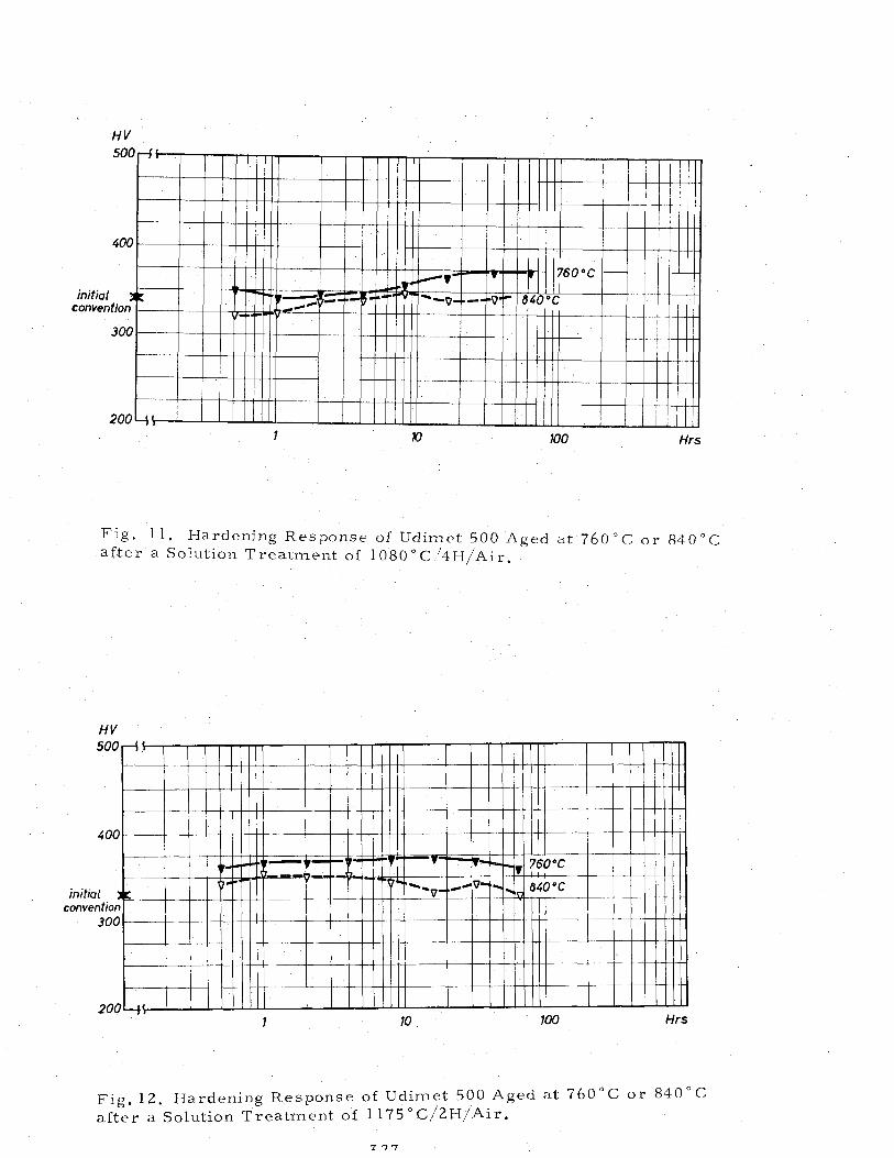
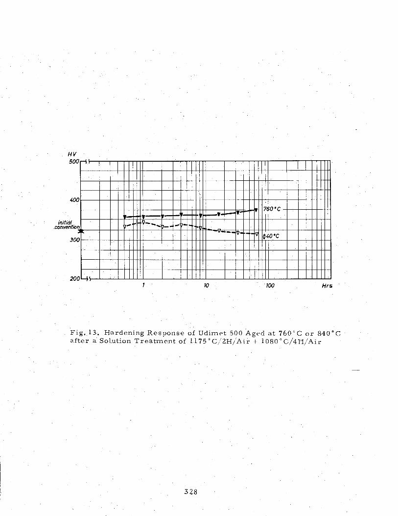
The hardness variation after the aging treatments described above is reproduced in Figures 11 to 13.
After the two-stage solution treatment and aging for 16 hours at 760 C,, the #' particle size is 450-700 A. For the same solution treatment and aging for 16 hours at 840 C, the f' size is 600-1200 A.
The M23C fi?
carbides precipitate at the grain bound.aries in the form of rods. T e fee carbides with a lattice parameter approximately three times that of the matrix are in epitaxial relationship with the latter (Figure 14). Specimens subjected, after the two-stage solution treat- ment, to the two-stage aging treatment exhibit a g' particle size of 350-1650 A. It is apparent that, during the 760 C aging, small &' particles have precipitated. In this case also, M23C6 carbides form at grain boundaries in epitaxy with the matrix.
PROLONGED AGING REACTIONS
Three-Stage Heat Treatment
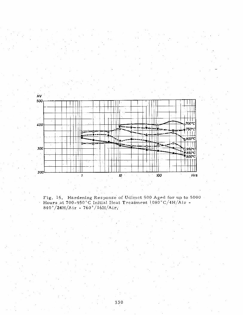
Specimens subjected to the three-stage heat treatment were exposed for up to 5,000 hours at temperatures from 700 to 950 C. The hardness variation during the prolonged treatment is reproduced in Figure 15.
315
7
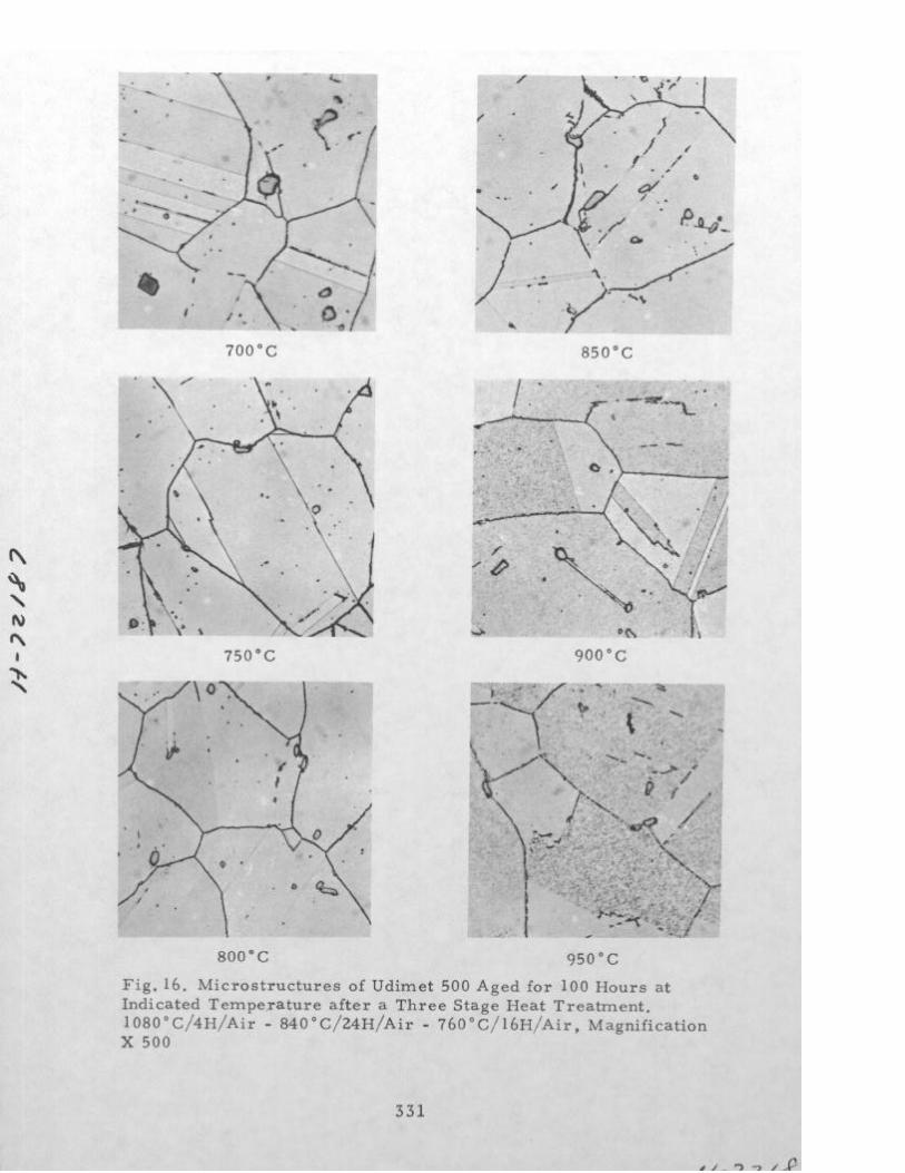
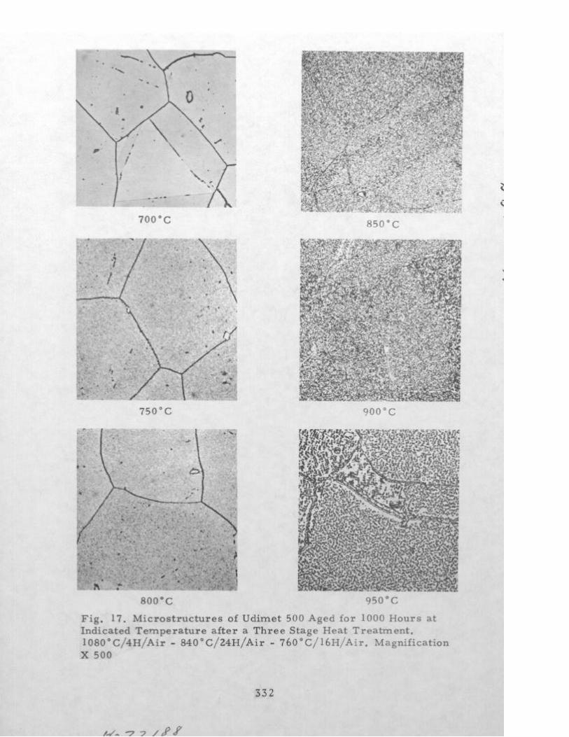
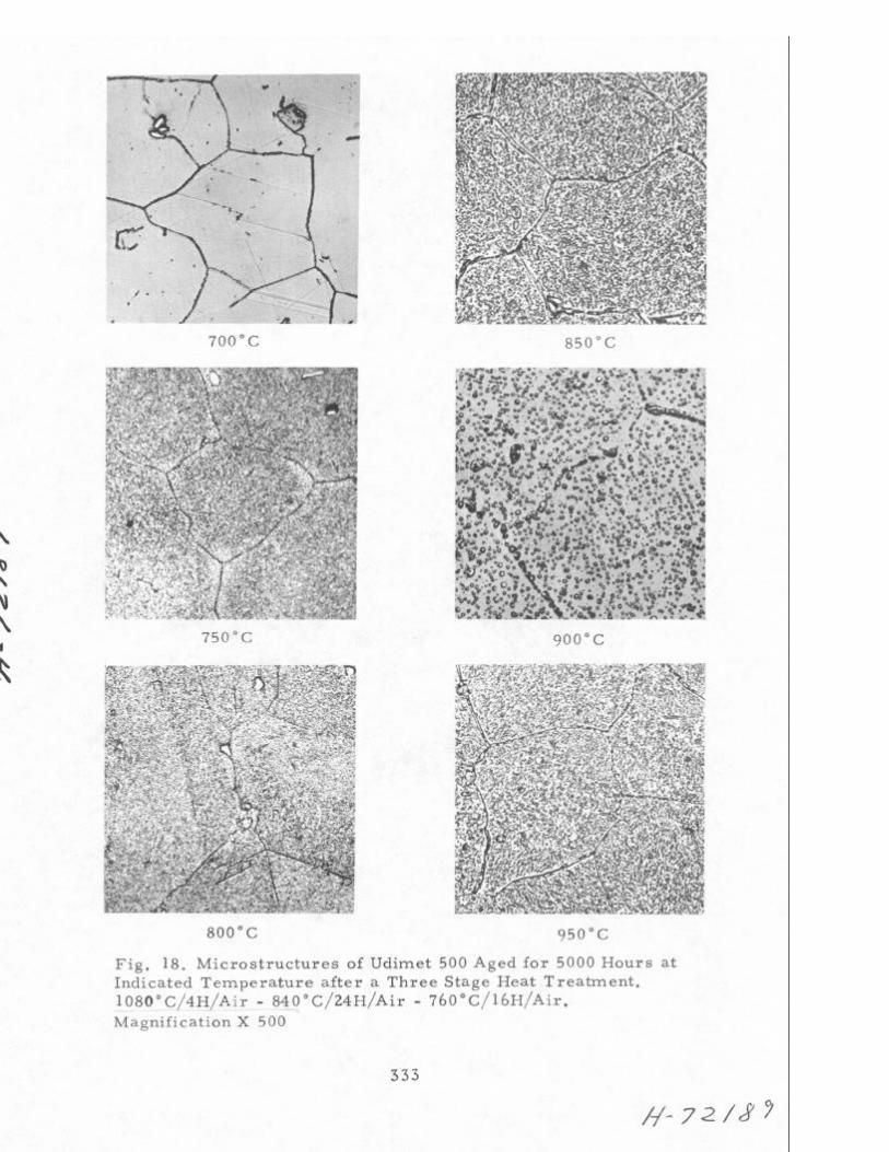
Figures 16, 17, and 18 reproduce the microstructures obtained . at different temperatures after 100, 1000, and 5000 hours, respectively.
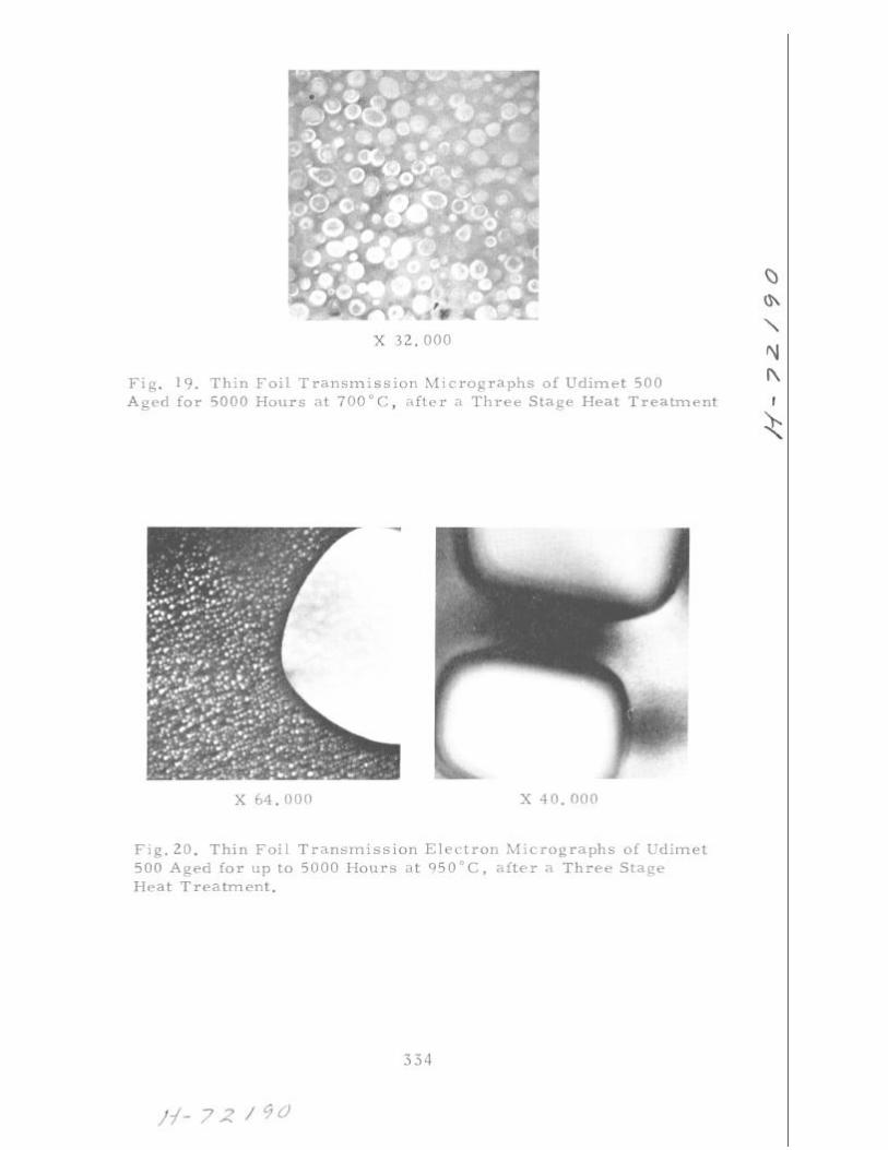
At 700 C no structural modification is apparent, even for the longest time considered. As shown in Figure 19 the particle size is 350-1700 A, i.e., the same as after the initial heat treatment. For the longer aging time the grain boundaries become more readily etched because - of the increase in the amount of precipitated carbides.' As the temper- ature increases the precipitation reactions become more pronounced. The -r' precipitates become visible on the optical micrographs, whereas the grain-boundary reactions results in their depletion ofr '.
The $' particles reach a size of 1800-14,000 A after 100 hours at 950 C and of 7,000-18,000.A after 5,000 hours at this temperature. Figure 20 shows that the large g"' particles have lost their spherical shape. They still have the same lattice parameter and remain apparently coherent. Along with the larger r' particles, much smaller particles (50-150 A) are visible*, which precipitated during the cooling from the aging temperature. M23C6 carbides have coarsened at the grain boundaries and also within the grains.
Four-Stage Heat Treatment
Specimens subjected to the four-stage heat treatment were sub- mitted to the same prolonged aging reactions as above.
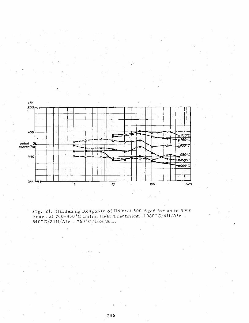
Figure 21 reproduces the variationof hardness after the aging treatments.
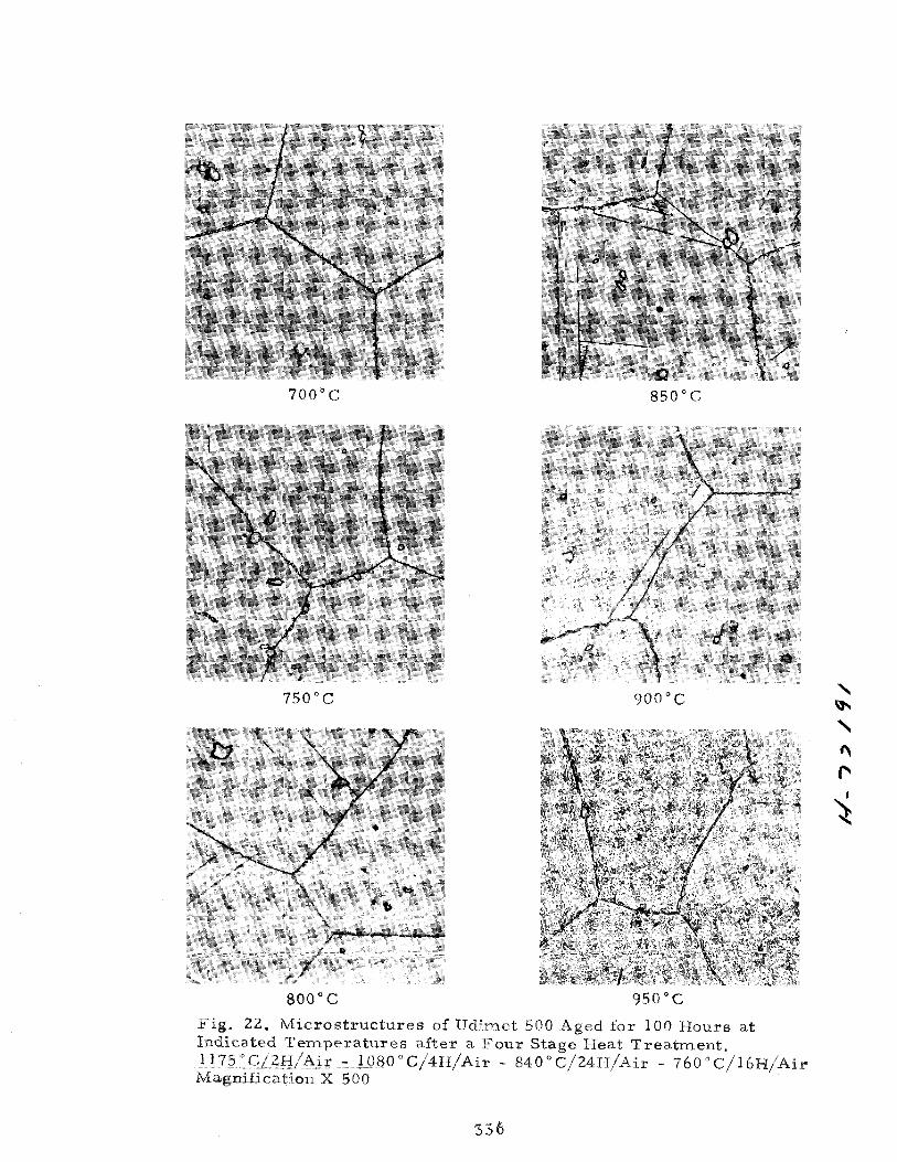
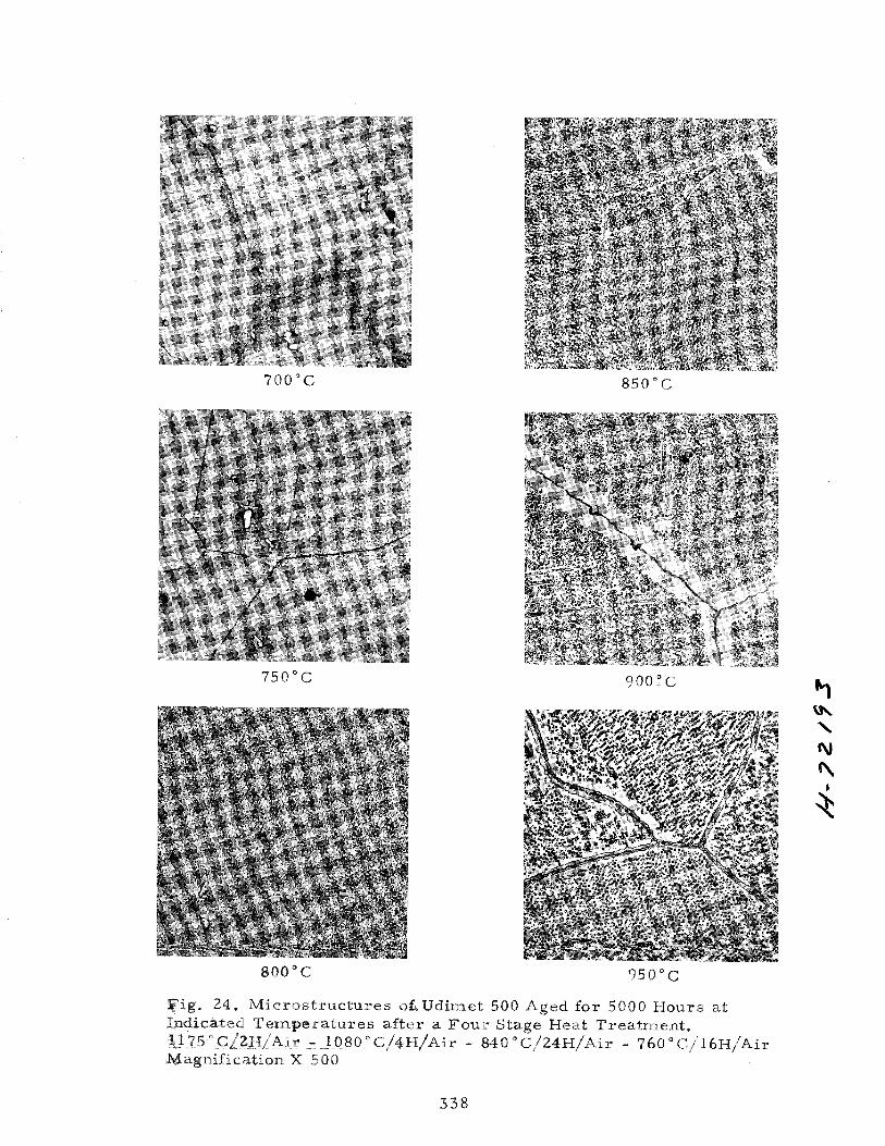
Figures 22, 23, and 24 shows the micro-structures of the alloy after 100, 1,000, and 5,000 hours, respectively, at different temper- atures. In all series of specimens the grain size is ASTM 2-3 instead of ASTM 4-5 as after the three-stage treatment. In these specimens the precipitation pattern is similar to that observed for the specimens subjected to the three-stage heat treatment. The grain-boundary reac- tions appear, however, to be more pronounced. Grain-boundary M23C6 carbides appear to be embedded within a phase that cannot be identified on the optical micrographs. Thin-foil transmission dark-field images showed that the carbides are surrounded by a continuous 5' phase. The %3C6 carbides also remain coherent with the matrix because of‘the parallel orientation of the lattices. Figure 25 shows typical views of carbides at grain boundaries and within the grains in specimens aged at 700 c.
The effect of prolonged exposure at elevated temperature on the room-temperature mechanical properties is illustrated in Table 2.
The prolonged exposure at 700 C results in a slight in- crease in the strength properties and a corresponding slight decrease in elongation. For the higher aging temperatures, a decrease in strength properties and a corresponding increase in elongation are observed. These observations are in agreement with the structural observations.
Prolonped Aping Under Stress
Three-Stage Heat Treatment
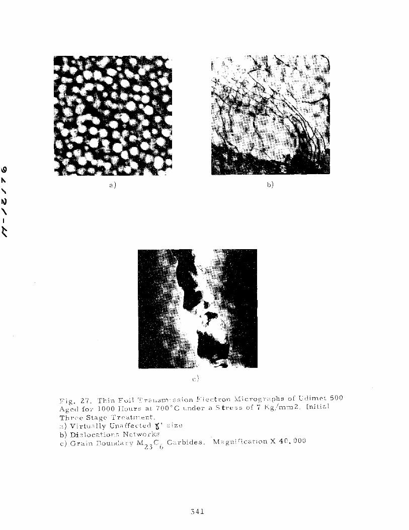
Specimens subjected to a three-stage heat treatment were maintained at 700 C for 1000 hours under a stress of 7 or 35 kg/mm2 and, for the same period, at 850 C under a stress of 3 or 15 kg/mm2. Metallographic examinations were made of the reduced section and of the practically unstressed head of the creep specimen.
The microstructures obtained of the specimens aged at 700 C are shown in Figure 26. There is a slight tendency for the grain boundaries to widen as the stress level increases. Figure 27 shows thin-foil transmission electron micrographs of the specimen stressed with 7 kg/mm2. The I' particles remained at practically the same size (500-1750 A) as before the stress-aging treatment. The grain- boundary carbides are in epitaxy with the matrix. Dislocation net- works showed that they have crossed the d ' particles.
The effect of this treatment on the room-temperature properties is shown in Table 3. Increasing the stress had no appre- ciable effect on the room-temperature tensile properties except for a decrease in elongation for the alloy that was creep tested at 850 C.
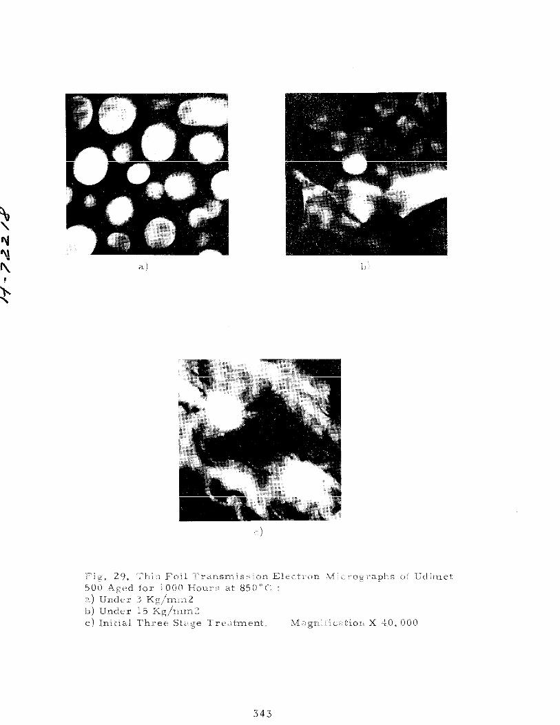
The effect of aging treatment under stress at 850 C on the microstructures is shown in Figure 28. Compared with the microstruc- ture obtained without stress (Figure 17), the grain boundary appears to be wider. The difference between the reduced-section and that of the head of the specimen is only slight. The $' particles have reached a size of about 5,000 A as shown in Figure 29. Comparing the results obtained without stress, it is apparent that coarsening of the
8' particles is due only to the temperature. The grain boundaries were shown to consist of discontinuoue %3C6 particles surrounded by&". A similar result was observed in optical micrographs of specimens ex- posed for 1,000 hours at 950 C (Figure 17).
The room-temperature tensile strength (Table 3) is lower after exposure for 1000 hours at 850 C under stress than after ex- posure under similar conditions at 700 C.
317
Four-Stage Heat Treatments
Specimens were subjected first to the four-stage heat treat- ment and then creep-rupture tested at temperature between 650 and 1,000 C and at stresses between 6 and 60 kg/mm2. Rupture time varied, depending on the stress and temperature, from a few hours to about 10,000 hours.
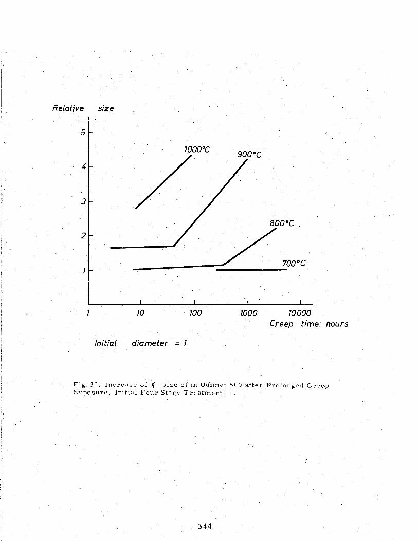
Examination of the reduced section and of the head of the ruptured specimens revealed that the &' particle size was dependent only on temperature and rupture time. This confirmed the findings (reported in the previous section) concerning the specimens subjected to the three-stage heat treatment. Figure 30 shows the relative in- crease in ?' particle size as a function of creep-rupture time for different temperatures.
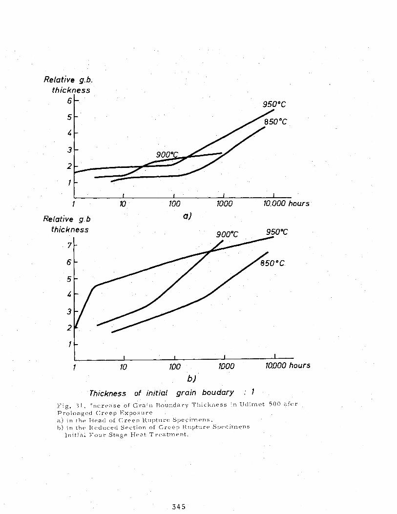
The grain-boundary reactions were assessed by their thickness as measured on optical micrographs obtained on similarly etched speci- mens. It was shown clearly that the carbide reactions were influenced largely by the stress conditions. Figure 31 illustrates the relative increase in grain-boundary thickness for the tests at 850, 900, and 950 c. The precise knowledge of the structural evolution of the alloy may prove useful in assessing the stress and temperature in a turbine blade when its actual time in service is known.
DISCUSSION OF THE RESULTS
For all the treatments considered in this study, the only phases identified were 6' or Ni3(A1, Ti), MC carbides, and C carbides. T 5 e observations are in-agreement with those and Beattie. 'ts
of 9 2gh However, no evidence was fou d for the presence of
a fee X phase, reported by Paliy)and Kaufmann If3) to precipitate in the grains. Hagel and Beattie have also observed the presence of sigma phase in a double-aged Udimet-500 alloy that was creep tested for 5,000 hours at 1350 F (732 C). In this study, no evidence was obtained of the presence of sigma phase either in the specimens creep tested for 1,000 hours or in the specimens aged for 5,000 hours. This behavior is in agreement with predictions from electron-vacancy calcula- tions(4), according to which Udimet-500 should not be considered as a sigma-prone alloy. The morphology of 8' and M23C6, as affected by heat treatments, to a large extent governs the properties of the alloy. Sev- eral investigations reported that optimum creep properties in nickel-base alloys are achieved by a large grain size, the precipitation of M.23C6 carbides at the grain boundaries, and the precipitation of r' by suit- able aging treatments.(2$3,and 5) An anneal treatment at 1175 C gives rise to a large grain size (ASTM 2-3) and results in the solutioning of all phases except that of MC carbides. Aging in this condition results, however, in the heterogeneous or cellular precipitation of M23C6 carbides from the supersaturated solid solution which is considered to be delete- rious.(4)
318
An additional treatment at the intermediate temperature 1080 C results in the partial precipitation of M23C6 carbides, preferable at the grain boundaries, and prevents, during subsequent aging, the heterogeneous precipitation of these carbides. In this respect the solution temperature of M23Cg carbides should be slightly higher than 1080 C rather than between 9 O-1080 C as reported by Kaufmann and Palty.(3) The solution treatment at 1080 C, practiced alone, results in a smaller grain size (ASTM 4-5) which is desirable when a high fatigue resistance is required.
The double-aging treatment gives rise to an optimum volume fraction of r' and particle sizes ranging from 350 to 1700 A.
Udimet-500 first subjected to a three- or four-stage heat treatment and then exposed for periods up to 10,000 hours, without stress or under stress, and at various temperatures does not form any compounds in addition to those formed during the initial heat treatment. Temperature affects both the increase in &" size and the grain-boundary reactions, whereas stress appears to affect only the increase in grain- boundary thickness. Grain-boundary recations are more pronounced in the alloy initially subjected to the four-stage treatment, which results in a larger grain size. Gamma prime particles are initially spherical
and, as the size increases, become cubic. Up to a particle size of 18,000 A the C' particles maintain practically the same lattice param- eter and remain coherent with the matrix.
The fee M23C6 carbide often is observed to grow at grain boundaries or within the grains in epitaxy with the matrix. Its lattice parameter is three times that of the solid solution. In many instances the grain boundaries where carbides have precipitated are surrounded with a & '-depleted matrix. Also M23C6 carbides appear to be surrounded with a J$' phase (see Figure 24). As discussed by S@$, chromium diffuses to the boundaries in order to form M23C6 carbide. In the chromium-depleted zones the solubility of r' increases, or the concentration of nickel and aluminum increases, and a continuous r' phase surrounding the carbides is formed. The grain-boundary reactions are enchanced by temperature, time at temperature, and stress level. The knowledge of the evolution of r ' size and grain-boundary thickness as a function of temperature, stress, and time permits the determination of the service conditions of a turbine component when its operation time is known.
Prolonged aging without stress or under stress of Udimet-500 subjected to a three- or four-stage heat treatment does not adversely influence the room-temperature elongation. At low temperature (n/700 C) a strengthening effect and a slight decrease in elongation were observed. Stress appears also to have only a small effect on room-temperature prop- erties. The effect of stress becomes more appreciable as the creep tem- perature increases.
319
REFERENCES
(1) Alloy Digest, Udimet-500, Engineering Alloy Digest Inc., New Jersey, October 1956.
(2) W. C. Hagel and H. 3. Beattie, Jr., Aging Reactions in Udimet-500 and M-252, Report DF 57-SL 349, General Electric Company Materials and Processes Laboratory, Rev., November 1958.
(3) M. Kaufmann and A. E. Palty, ~The Relationships of Structure to Mechanical Properties in Udimet-500, Trans. AIME, 218, 1960, 107.
(4) C. T. Sims, Contemporary View of Ni-Base Super$lloys, J. Metals, 1119, October 1966.
(5) W. Betteridge, The Nimonic Alloys, Edward Arnold Ltd, London, 1959.
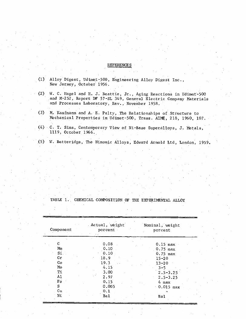
TABLE 1. CHEMICAL COMPOSITION OF THE EXPERIMENTAL ALLOY
Component Actual, weight Nominal, weight
percent percent
C Mn Si Cr co MO Ti Al Fe S cu Ni
0.08 0.10 0.10
18.9 19.3 4.15 3.00 2.97 0.15 0.005 0.1 Bal
0.15 max 0.75 max 0.75 max 15-20 13-20
3-5 2.5-3.25. 2.5-3.25 4 max 0.015 max
Bal
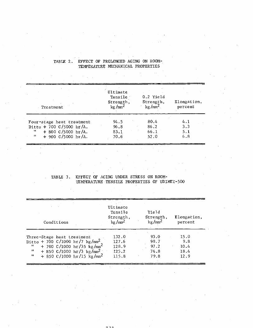
TABLE 2. EFFECT OF PROLONGED AGING ON ROOM- TEMPERATIJRR MEXHANICAL PROPERTIES
Treatment
Ultimate Tensile 0.2 Yield
Strength, Elongation, kg/mm2
Strength, kg/mm2 percent
Four-stage heat treatment 94.5 80.4 4.1 Ditto + 700 C/5000 hr/A. 96.8 86.2 3.3
11 + 800 C/5000 hr/A. 83.1 66.1 5.1 1, + 900 C/5000 hr/A. 70.6 52.0 6.8
TABLE 3. EFFECT OF AGING UNDER STRESS ON ROOM- TEMPERATURE TENSILE PROPERTIES OF UDIMET-500
Conditions
Ultimate Tensile
Strength, kg /mm2
Yield Strength, Elongation,
kg/mm2 percent
Three-Stage heat treatment 132.0 93.0 15.0 Ditto + 700 C/l000 hr/7 kg/mm2 127.6 98.7 9.8
11 + 700 C/l000 hr'/35 kg/mm2 128.9 97.2 10.4 11 + 850 C/l000 hr/3 kg/mm2' 125.2 74.8 18.4 (1 f 850 C/l000 hr/15 kg/mm2 115.8 79.8 12.9
I II I
I I I I II.III I I llll/ll
l---i-t ’ ’ ’ WA’TER
200 I III1 10-1 1 10 min
Fig. 1. Effect of Cooling Rate from 12OO”C,/4 hours 6n Hardness of Udimet 500
2 4 6 8 Hrs
Fig. 2. Effect of Temperature, Time at Temperature and Cooling Rate on Hardness of Udimet 500
I
a) X 100.000 b) X 32.000
Fig. 3.. Thin Foil Electron Micrographs of Udimet 500 Water Quenched from 1175”C/2 hours. a)\(’ Ni3 (Al-Ti) precipitates
b) Dislocations pairs.
J \ -34 ; .
.
/ . ‘Q
a) X 500 b) X 5000
Fig. 4. Microstructure of Udimet 5OOSubjec9ed to a Two Stage Solution Treatment : 1175”C/2 hours/air t, 108O”C/4 hours/Air M,,C,
323 Coutsouradis.
1 hrs.
1 hrs.
~~~~,~~~~.~~~~: 64 hrs. I .
32 hrs.~-~.-~,r : ‘-*- . !
l i** . .
. .
4 ‘..,
.:
f . ;* I
z .’ ;. \ ‘.. .
760°C 840°C
Fig. 5 and 6. Microstructures of Udimet 500 Aged for Indicated Times at 760°C and at 840°C after a Solution Treatment of 1175”C/2H/Air, Magnification X 500
324
1 hrs.
4 hrs.
16 hrs.
64 hrs.
Y,
t * * ‘i \
. 6: s : I;., :
-I * ‘! 1’ ‘;. , . ’ , , iJ ;* 1
840°C
Fig. 7 and 8. .Microstructures of Udimet 500 Aged for Indicated Times at 760 and at 840 “C after a Solution Treatment of 1080’ C/t?l:H/Air , Magnification X 500
325
760°C
1 “hrs.
4 hrs.
16 hrs.
64 hrs.
840°C
Fig. 9 and 10. Microstructures of Udimet 500 Aged for Indicated Times at 760°C and 840°C after a Solution Treatment of 1175”C/2H/Air t 108O”C/4H/Air, Magnification X 500.
326
HV
1 W 100 UC5
Fig, 11, Hardening Response of Udimet 500 Aged at 760°C or 840°C after a Solution Treatment of 1080°C ‘4H/‘Air.
HV
t-4 I I IllIll I llllllll HI
Fig. 12. Hardening Response of Udimet 500 Aged at 760°C or 840°C after a Solution Treatment of 1175”C/2H/Air.
HV 500
Fig, 13. Hardening Response of Udimet 500 Aged at 760°C or 840 “C after a‘ Solution Treatment of 1175”C/2HjAir + 1080”C/4H/Air
-
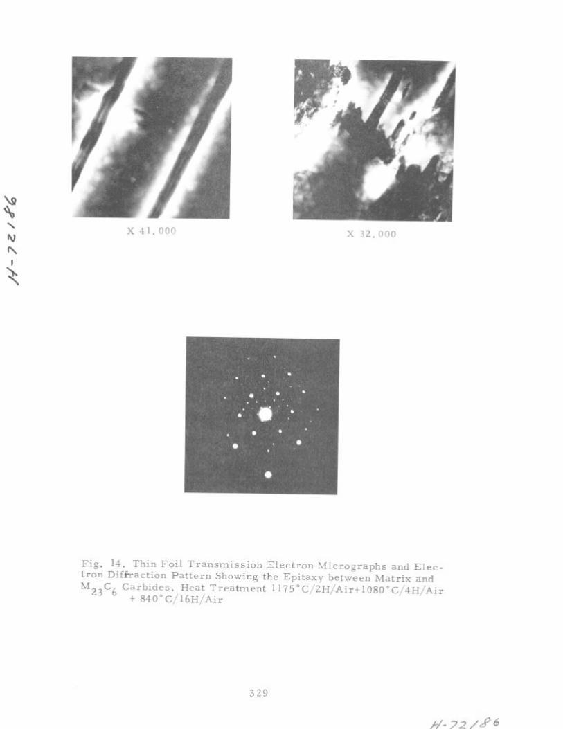
Fig. 14. Thin Foil Transmission Electron Micrographs and Elec- tron Diffraction Pattern Showing the Epitaxy between Matrix and M23C6 Carbides, Heat Treatment 1175”C/2H/AirflO8O”C/4H/Air
t 840”C/16H/Air
329
f/-72/
HV 500
I I L
-o- 400
I -L-r\-. !ll! ly+ .7 . -\.
, +pw-cl I ““’
300,
I 200
1 10 100 Hrs
Fig. 15. Hardening Response of Udimet 500 Aged for up to 5000 Hours ,at 700-950°C Initial Heat Treatment 1080”C/4H,/Air - 840”/24H/Air - 760”/16H/Air.
c- -c
I
8 .:
‘, 3 @c1 1 i
900°C
800°C 950°C
Fig. 18. Microstructures of Udimet 500 Aged for 5000 Hours at Indicated Temperature after a Three Stage Heat Treatment. 1080”C/4H/Air - 840°C/24H/Air - ‘760”C/l6H/Air. Magnification X 500
333
H- 72
Q cs\ \
x 32.000 ‘\s
Fig. 19. Thin Foil Transmission Micrographs of Udimet 500 n
Aged for 5000 Hours at 7OO”C, after a Three Stage Heat Treatment I
Fig. 20. Thin Foil Transmission Electron Micrographs of Udimet 500 Aged for up to 5000 Hours at 95O”C, after a Three Stage Heat Treatment.
334
/v- 72 150
HV 500
400 i
initial J conventi
--- -
---wweC
I I I I Illll I I I IIIL
200. :: 1 I t111111 1 W 100 HrS
Fig. 2,l. Hardening Response of Udimet 500 Aged for up to 5000 Hours at 700-950°C Initial Heat Treatment. 1080”C/4H/Air - 840”C!24H/Air - 760°C/16H/Air.
335
850°C
750°C
800°C
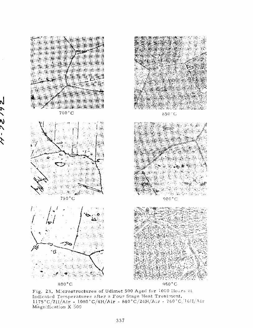
Fig. 23. ~ic~~s~~uc~u~es of Udimet 500 Aged for 1000 Hours al. Indicated Temperatures after a Four Stage Neat Treatment* 1175”C/2EJ/Air - 108~O~~4~/A~~ - 840~~~2~~/Ai~ - 60a~~161--I/Air Magnification X 500
337
850°C
24,
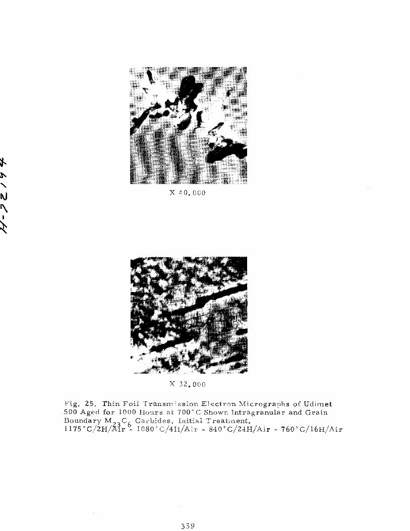
Fig, 25. Thin Foil Tr~~srn~~si~~ Electron Micrographs of Udimet 500 Aged far IO00 Hours at 00 o C Shown Intragranular and Grain Boundary M C Carbides B Initial Treatment, 1175”C/2H,/.&~x 6, l~80°~~4~~Ai~ - 84O”C/Z4H/Aix - 760”C/16H/Air
339
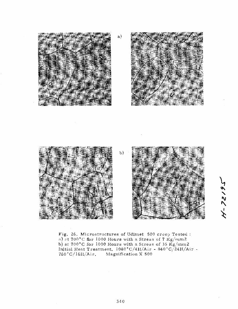
Fig. 26, Microstructures of Udimet 500 creep Tested : a) at 7QO”C for 1000 Hours with a Stress of 7 Kg/mm2 b) at 7’00°C for 1000 Hours with a Stress of 35 Kg/mm2 ~~iti~~ Heat Treatment. 1080”C/4H/Air - 840”C/24H/Air - “GO”C/16H/Air. Magnification X 500
340
341
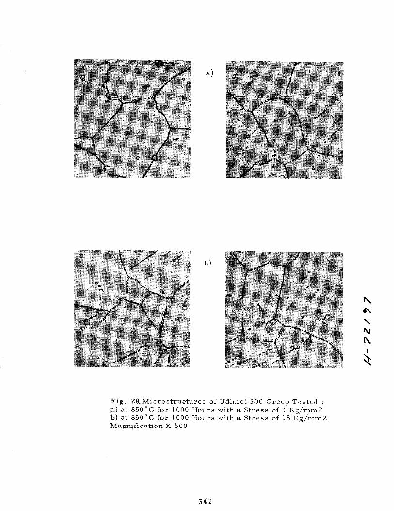
Fig. 28,Mic~~struct~r~s of Udimet 500 Creep Tested : a) at 850°C for 1000 Hours with a Stress of 3 Kg/mm2 b) at 850°C for 1000 Hours with a Stress of 15 Kg/mm2 ~~~~~~~~~~~0~ x 500
342
a)
343
Relative size
1
I I I I
1 10 100 IOQO 10.000 Creep time hours
Initial diameter = 1
Fig. 30. Increase of 8 ’ size of in Ud’imet 500 after Prolonged Creep Exposure. Initial Four Stage Treatment. I
Relative g. 6. thickness
6-
s-
4-
3-
1 I I
10 700 I
1000 I
10.000 hours
Relative g. b
I I I
100 moo 10000 hours
6)
Thickness of initial grain boudary : 1
Fig. 31, Increase of Grain Boundary Thickness in Udimet 500 afer Prolonged Creep Exposure a) in the Head of Creep Rupture Specimens. b) in the Reduced Section of Creep Rupture Specimens
Initial Four Stage Heat Treatment.
345