Embed Size (px)
Citation preview
STUDY OF CAVITATION DAMAGE TO HIGH-PURITY METALS AND A NICKEL-BASE SUPERALLOY I N WATER
by Stanley G. Young
Lewis Research Center i Cleveland, Ohio 441 35 I
NATIONAL AERONAUTICS A N D S P A C E ADMINISTRATION WASHINGTON, D. c. SEPTEMBER 1970
-. 1
https://ntrs.nasa.gov/search.jsp?R=19700029252 2018-07-18T16:13:46+00:00Z

-,- . r
19. Security Class i f . (of t h i s report)
Unclassified
TECH LIBRARY KAFB, NM
20. Security Classi f . (of t h i s page) 21. NO. o f Pages 22. P r i c e *
Unclassified 1 ~ - 3 2 I $3.00
1. Report No. NASA TN D-60
2. Government Accession No.
- i 4 __ 4. T i t l e and Subt i t le STUDY OF CAVITATION DAMAGE TO
HIGH-PURITY METALS AND A NICKEL-BASE SUPER- ALLOY IN WATER
__ _ _ __ 7. Author(s)
Stanley G, Young
Lewis Research Center National Aeronautics and Space Administration Cleveland, Ohio 44135
National Aeronautics and Space Administration Washington, D. C. 20546
9. Performing Organizat ion Name and Address
_ _ ~ _ _ 2. Sponsoring Agency Name and Address
__ .. - 5. Supplementary Notes
~ - 6. Abstract
0132663 - ~
3. Recipient’s Catalog No.
5. Report Date September 1970
6. Performing Organization Code
8. Performing Organization Report No. E-5688
IO. Work Un i t No. 129 YO 3
11. Contract or Grant No.
~ ___ 13. Type o f Report and Per iod Covered
Technical Note
. -.
14. Sponsoring Agency Code
Stationary specimens of unalloyed zinc, nickel, iron, and tantalum and Udimet 700 were subjected t o cavitation damage in water by means of a vibratory apparatus. Most t e s t conditions were those established in an earlier ASTM round robin. Damage was maximum a t separation dis tances of the specimen from a vibrating head of 0.015 to 0.020 inch (0.038 to 0.051 cm). The damage to stationary specimens was about half the damage t o vibrated specimens of the s a m e mater ia l . Cavitation damage was measured by volume loss and by surface roughness. Metallographic studies were conducted to determine the nature of damage.
.. ._
17. Key Words (Suggested b y Authorcs))
Cavitation; ultrasonic vibration; erosion; corrosion; liquid impingement; zinc; nickel; iron; tantalum; Udimet 700; metallography
18. Dis t r ibut ion Statement
Unclassified - unlimited
STUDY OF CAVITATION DAMAGE TO HIGH-PURITY METALS
AND A NICKEL-BASE SUPERALLOY IN WATER
by Stanley G. Young
Lewis Research Center
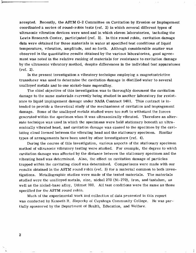
SUMMARY
Unalloyed zinc, nickel, iron, and tantalum and Udimet 700 were subjected to cavi-
Other test conditions were those estab- tation damage in water. A vibrating head generated a cavitation cloud which impinged on stationary specimens of the tes t materials. lished ear l ier in an ASTM round robin.
The order of decreasing cavitation damage based on both volume loss and surface roughness after approximately 400 minutes, w a s zinc, annealed nickel 270, iron, as- received nickel 270, tantalum, and Udimet 700. The effect of separation distance be- tween specimens and the vibrating head w a s determined, and the peak damage w a s found to be at separation distances of 0.015 to 0.020 inch (0.038 to 0.051 cm).
Damage to stationary specimens w a s found to be generally less than 50 percent of the damage sustained by vibrating specimens of the same material. Preferential dam- age observed in all the specimens indicated that cavitation may be useful as a mechan- ical etching technique in situations where reactive chemicals would be undesirable. Examination of cross-cut specimens showed undercutting, transgranular cracking, and subsurface deformation, the same types of damage characterist ics observed in ear l ier tes ts of steels and superalloys in sodium.
I NTRODUCTI ON
Cavitation damage to materials occurs in many different engineering applications where bubbles, formed by transient low pressures in moving liquids colla.pse rapidly on or near solid surfaces. A recent excellent review of the field of cavitation erosion, as well as erosion by solid and liquid impingement can be found in reference 1.
damage in the laboratory, the ultrasonic vibration technique has become the most widely Of the various possible methods of evaluating materials for resistance to cavitation
accepted. Recently, the ASTM G-2 Committee on Cavitation by Erosion or Impingement coordinated a series of round-robin tes t s (ref. 2) in which several different types of ultrasonic vibration devices were used and in which eleven laboratories, including the Lewis Research Center, participated (ref. 3). In this round robin, cavitation damage data were obtained for three materials in water at specified test conditions of liquid temperature, vibration, amplitude, and so forth. Although considerable scatter was observed in the quantitative resul ts obtained by the various laboratories, good agree- ment w a s noted in the relative ranking of materials for resistance t o cavitation damage by the ultrasonic vibratory method, despite differences in the individual test apparatuses (ref. 2).
In the present investigation a vibratory technique employing a magnetostrictive transducer w a s used to determine the cavitation damage in distilled water t o several unalloyed metals and to one nickel-base superalloy.
damage to the same materials currently being studied in another laboratory for res is t - ance to liquid impingement damage under NASA Contract 1481. This contract is in- tended to provide a theoretical study of the mechanisms of cavitation and impingement damage. Some of the unalloyed metals studied w e r e too soft to withstand the forces generated within the specimen when it w a s ultrasonically vibrated. Therefore an alter- nate technique w a s used in which the specimens were held stationary beneath an ultra- sonically vibrated head, and cavitation damage w a s caused to the specimen by the cavi- tating cloud formed between the vibrating head and the stationary specimen. types of arrangements have been used by other investigators (ref. 4).
During the course of this investigation, various aspects of the stationary specimen method of ultrasonic vibratory testing were studied. For example, the degree to which cavitation damage w a s affected by the distance between the stationary specimen and the vibrating head w a s determined. Also, the effect on cavitation damage of particles trapped within the cavitating cloud w a s determined. results obtained in the ASTM round robin (ref. 3) for a material common to both inves- tigations. Metallographic studies were made of the tested materials. The materials studied were the unalloyed metals, zinc, nickel 270 (Ni-270), iron, and tantalum, as well as the nickel-base alloy, Udimet 700. specified for the ASTM round robin.
was conducted by Kenneth R. Slepecky of Cuyahoga Community College. tially sponsored by the Department of Health, Education, and Welfare.
The chief objective of this investigation w a s t o thoroughly document the cavitation
Similar
Comparisons were made with our
All test conditions were the same as those
Much of the experimental work and collection of data presented in this report He was par-
2
\
MATERIALS, APPARATUS AND PROCEDURE
Mater ia Is
The materials investigated for cavitation damage in water were the unalloyed met- als, zinc, as-received Ni-270, annealed Ni-270, iron, and tantalum, and Udimet 700, a nickel-base superalloy. All materials except as-received Ni-270 were obtained from Dr. 0. G. Engel, General Electric Company, Cincinnati, Ohio. The chemical compo- sitions and conditions of heat treatment a l so received from Dr. Engel, are listed in ta- ble I. All heat treatments were performed after machining of the specimens unless otherwise stated. tested in both the as-received and the annealed conditions. tested in an ASTM round robin in the as-received condition with no heat treatment after machining of the specimens (ref. 3).
Physical properties of the metals are listed in table 11. Nickel w a s This material was previously
Cavitation Damage Apparatus
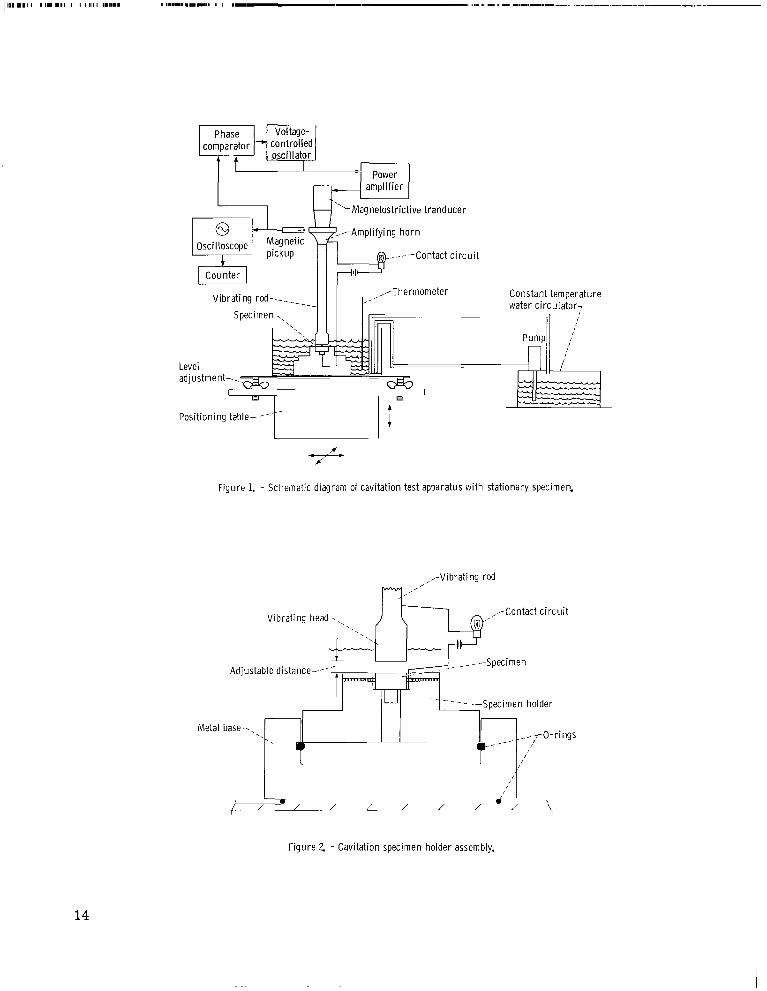
A schematic diagram of the apparatus used is shown in figure 1, and a more de- tailed schematic diagram of the specimen and holder assembly is shown in figure 2. magnetostrictive transducer w a s used to vibrate a rod with its free end immersed in distilled water. This end of the vibrating rod, called the vibrating head, w a s detachable and made from L-605, a moderately cavitation-damage-resistant material. The head w a s replaced three t imes during the entire program, although very little damage w a s noted to the L-605. The test specimen, shown in the figure, is mounted directly below the vibrating head. Cavitation bubbles induced in the water by vibration collapsed on the face of the stationary specimen where they caused damage.
A feedback signal from the magnetic pickup w a s used to control the transducer input frequency to match the natural resonant frequency of the transducer assembly which w a s approximately 25 000 hertz. Level and translational adjustments and a contact c i r - cuit were used to position vibrating head and specimen surfaces and in obtaining parallel measured gaps between the specimen and the vibrating head. Water temperatures were maintained constant by a water circulator capable of either heating or cooling the dis- tilled water test fluid.
A
A s shown in figure 1 a magnetic pickup w a s used to monitor the vibration amplitude.
3
S peci m ens
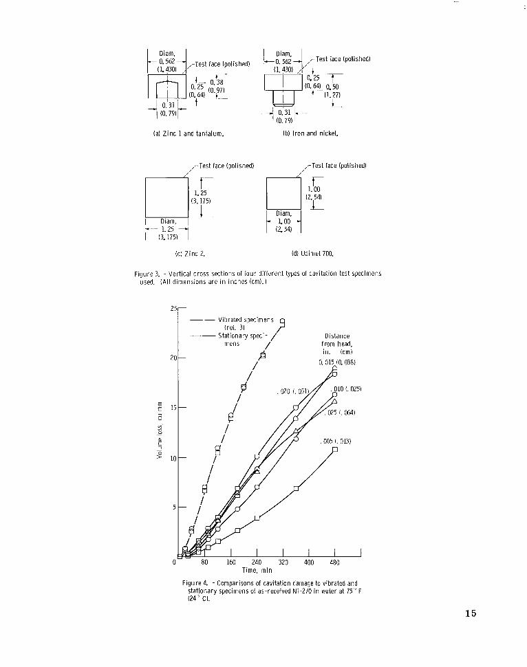
The several different types of test specimens used in these experiments are shown in figure 3. The threaded specimens shown in figures 3(a) and (b) were designed for earlier experiments in which the specimens were vibrated; however, the soft zinc speci- mens could not withstand forces generated in the threads by vibration. Therefore, all specimens were tested in the stationary position explained in the previous section. One specimen each of zinc and Udimet 700 shown in figures 3(c) and (d) was not threaded and was larger in diameter than others to study the effect of specimen diameter on the damage pattern. The surfaces of all specimens were polished metallographically before test except for as-received nickel 270. These specimens were ground to a 600 paper finish.
Test Conditions
The test conditions for cavitation damage were made to conform with those previ- ously specified by the ASTM for the round-robin tes t s in which eleven laboratories par- ticipated (ref. 2). The primary exceptions to the round-robin conditions were that specimens were held stationary and face up under a vibrating head.
All tes ts were made in distilled water a t 75*1° F (24' C). Local atmospheric pressure was 29.17+0.25 inches of mercury (1x10 N/mX).
The total displacement (double amplitude) of the vibrating head w a s 0.00175~0.00005 inch (4. 45X10-2 mm). The suggested amplitude for the round-robin tes t s w a s 0.002 inch (5. 1X10⁻² mm). The amplitude of 0.00175 inch (4. 45X10-2 mm) w a s used in our tes t s of both vibrated and stationary specimens because of limitations of the equipment at the high frequency used. The nominal frequency of vibration w a s 25 000 hertz.
The distance between the specimen and vibrating head w a s held at 0.015 inch (0.038 cm) for all tes t s except those which were made t o determine the effect of sepa- ration distance on cavitation damage.
5
Test Procedure
Specimens were cleaned in distilled water and alcohol and air dried; then they were photographed and weighed. After the test bath w a s brought to the desired temperature, specimens were securely placed in the specimen holder, and the specimen and holder were placed into the test bath. The specimen assembly w a s then adjusted to place the specimen surface directly below the L-605 head and to a s su re parallel surfaces between the specimen and head. The specimen assembly w a s then raised until contact w a s made
4
with the L-605 head as indicated by a contact circuit light. Then the specimen w a s backed away t o the desired separation distance for the test. Distance was measured to the nearest 0.001 inch (0.025 mm) by a dial on the positioning table. supplied to the magnetostrictive vibrator and the specimens were subjected to cavitation for varying intervals. After each period of operation, the specimens were removed from the bath, cleaned, weighed, and photographed. Finally, surface roughness t races of the uniformly damaged portions of the specimens were obtained with a linear profiler having a diamond stylus with a 0.005-inch (0. 127-mm) radius and a cone angle of 51. 5'. Usually a single t race approximately 0.25 inch (0.63 cm) in length w a s taken.
ically to determine the nature and depth of cavitation attack.
Power w a s then
After testing, some specimens were sectioned axially and examined metallograph-
RESULTS AND DISCUSSION
Determination of Optimum Separation Distance Between
Specimen and Vibrat ing Head
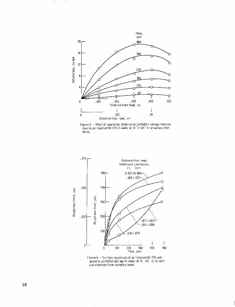
The cavitation damage t o as-received Ni-270 at various separation distances be- tween the specimen and vibrating head is summarized in table I11 and plotted in figure 4. This figure also shows the resul ts of ASTM round-robin tes t s with vibrating specimens of the same material (ref. 3). For most separation distances, the cavitation damage to the stationary specimen w a s l e s s than one-half the damage sustained by vibrating speci- mens. tion exposure t imes in figure 5. tion w a s observed at approximately 0.015 inch (0.038 cm). gave the most nearly linear damage curve (see fig. 4). Therefore, this value w a s chosen as a "standard" gap to be used for tes t s of all other materials. shorter than 480 minutes, a maximum in damage occurred at a separation of 0.020 inch (0.041 cm).
Further studies of the effect of separation distance on cavitation damage were made by making surface roughness t races at various t imes during the tests. these measurements a r e shown in figure 6. With one exception for a given test time the greater the separation distance (from 0.010 to 0.025 in. (0.025 to 0.064 cm)) the rougher the damage surface. The one exception w a s above 400 minutes; the 0.005-inch (0.013-cm) curve crossed the 0.010-inch (0,025-cm) curve. It is postulated that bub- bles further away from the vibrating head may be larger and cause a more deeply cra- tered, coarser damage surface than smaller bubbles near the head. However, because the total damage is not greater at these larger distances (fig. 5), the number of these
Volume loss is plotted against separation distance for several different cavita- The maximum damage for tes ts of 480 minutes dura-
Moreover th i s separation
For test t imes
The resul ts of
5
larger bubbles should decrease with distance. At 0.015 to 0.020 inch (0.038 t o 0.051 cm) optimum combinations of bubble s ize and number may exist t o cause maxi- mum damage.
Comparisons of Materials
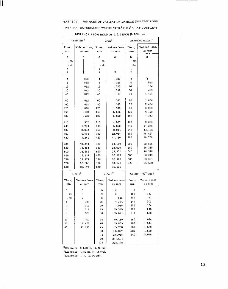
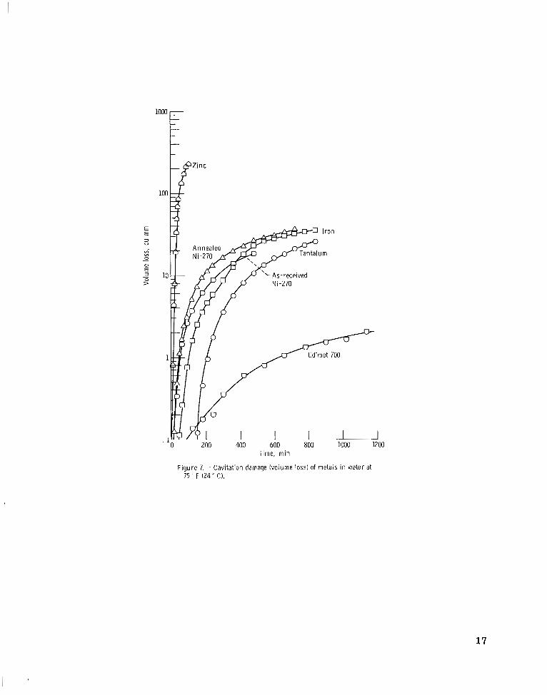
Cavitation damage resul ts for all materials are expressed in t e r m s of volume loss in table IV. Volume loss curves for these materials are shown in figure 7. Because the curves for zinc and Udimet 700 are separated by three orders of magnitude, it was necessary to plot the volume loss on a logarithmic scale to include both materials on the same plot. Zinc lost approximately 233 cubic mill imeters during 105 minutes of test, while Udimet 700 lost only 2 cubic mill imeters in 1140 minutes. Annealed Ni-270 was less resistant to cavitation damage than Ni-270 in the as-received condition. This probably resulted from the lower hardness of the annealed nickel when compared to the as-received nickel. resul ts which fell between those of the as-received and annealed nickel specimens. Tantalum was the most resistant of the unalloyed metals that were tested.
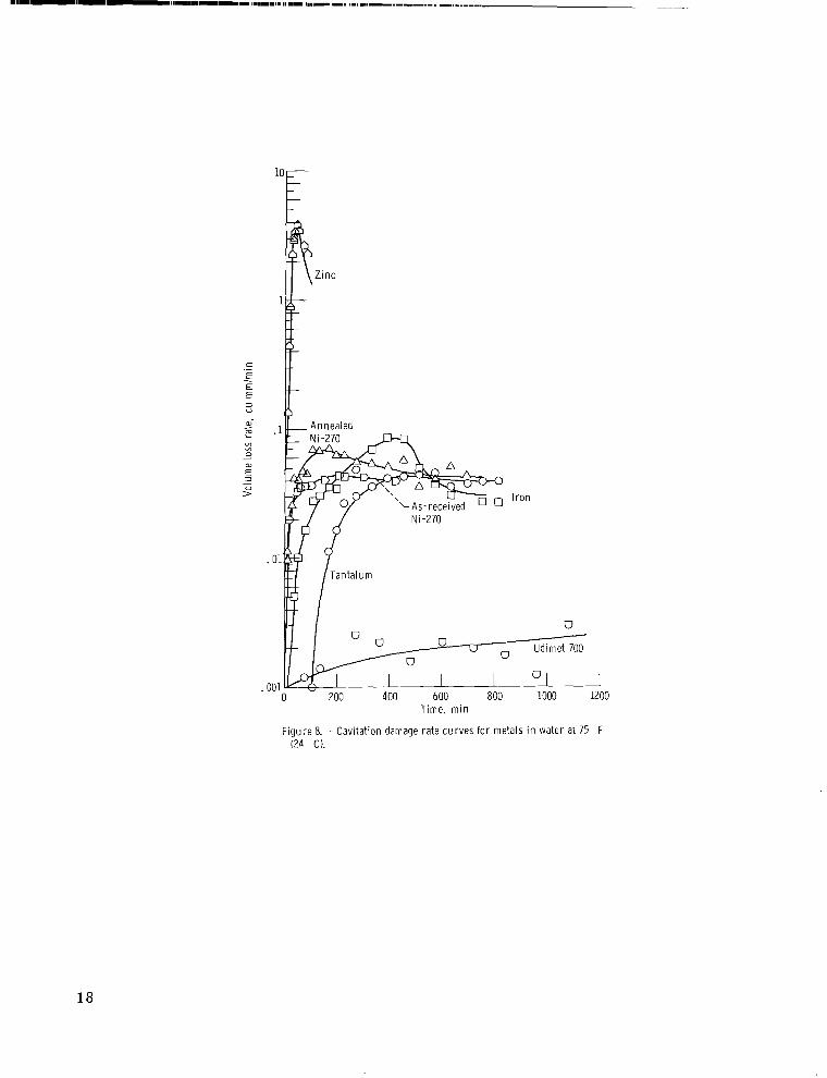
Volume loss ra te curves for the tes t mater ia ls are presented in figure 8. These curves followed patterns s imilar to volume loss ra te curves established previously for vibrated specimens in sodium and mercury (ref. 5); but much more scatter w a s present and "steady-state'' rates did not develop for all the test materials. Also, the iron specimen which had a high peak (above both nickel specimens and tantalum), had a lower "steady-state'' rate. This behavior may be due t o receding damage surfaces of the test specimens. Because the actual damaged surface has receded, a gap exists that is wider than measured. The gap measurement was always made from the relatively undamaged r im of the tes t specimen. As shown earlier in figure 5, i f this gap w a s greater than approximately 0.020 inch (0.051 cm) the damage w a s reduced.
From this figure it can be seen that the materials are clearly ranked in the same order as shown in the ear l ier volume loss curves (fig. 7); the as-received nickel and i ron curves even cross each other a t approximately the same time in both figures.
After about 400 minutes, the iron specimen showed volume loss
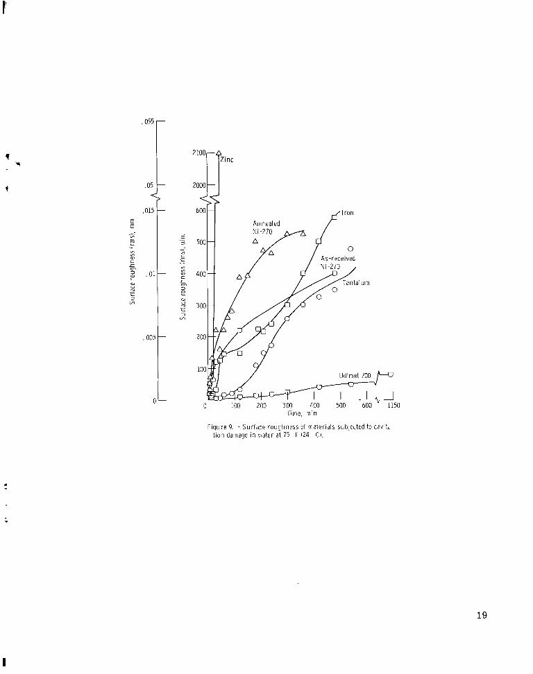
Surface roughness measurements f o r all the mater ia ls a r e shown in figure 9.
Metallography
Comparisons of ~ - - tested ~ ~. . . . specimens. . . . - Macrcgraphs were taken of all the specimens
These were exposed to cavitation damage in tested. of the as-received Ni-270 specimens. water at 75' F (24' C) for t imes up to 480 minutes and for separation distances from
These are included in figures 10 to 12. Figure 10 shows the damaged surfaces
6
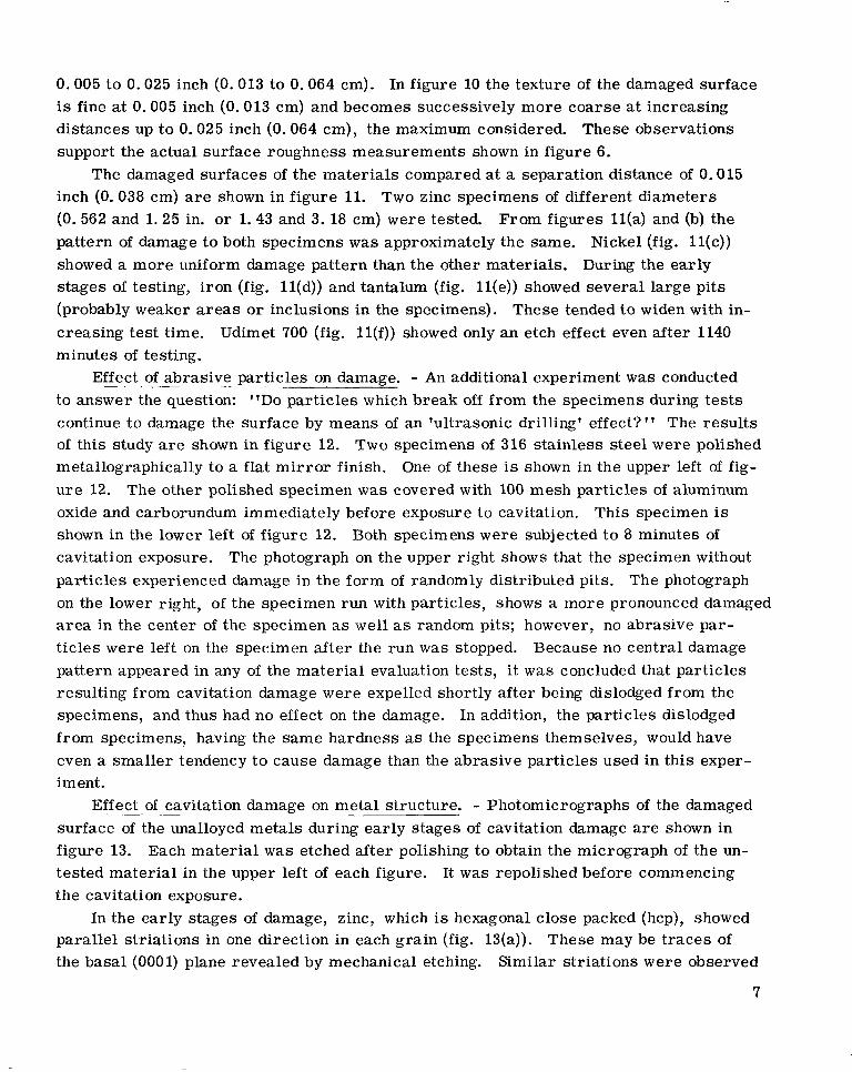
0.005 to 0.025 inch (0.013 to 0.064 cm). In figure 10 the texture of the damaged surface is fine at 0.005 inch (0.013 cm) and becomes successively more coarse at increasing distances up to 0.025 inch (0.064 cm), the maximum considered. These observations support the actual surface roughness measurements shown in figure 6.
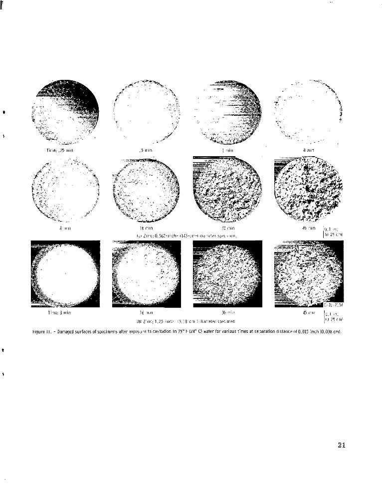
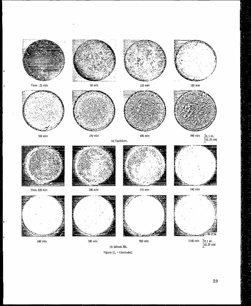
inch (0.038 cm) are shown in figure 11. Two zinc specimens of different diameters (0. 562 and 1.25 in. o r 1.43 and 3. 18 cm) were tested. From figures ll(a) and (b) the pattern of damage to both specimens w a s approximately the same. Nickel (fig. l l(c)) showed a more uniform damage pattern than the other materials. During the early stages of testing, iron (fig. ll(d)) and tantalum (fig. l l(e)) showed several large pits (probably weaker areas or inclusions in the specimens). creasing test time. Udimet 700 (fig. l l ( f ) ) showed only an etch effect even after 1140 minutes of testing.
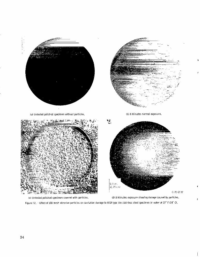
Effect - of ~ abrasive _. particles on damage. - An additional experiment w a s conducted to answer the question: "DO particles which break off from the specimens during tes t s continue to damage the surface by means of an 'ultrasonic drilling' effect?'' The results of this study a r e shown in figure 12. Two specimens of 316 stainless steel were polished metallographically to a flat mi r ro r finish. One of these is shown in the upper left of fig- ure 12. oxide and carborundum immediately before exposure to cavitation. shown in the lower left of figure 12. Both specimens were subjected t o 8 minutes of cavitation exposure. particles experienced damage in the form of randomly distributed pits. on the lower right, of the specimen run with particles, shows a more pronounced damaged a r e a in the center of the specimen as well as random pits; however, no abrasive par- t icles were left on the specimen after the run w a s stopped. Because no central damage pattern appeared in any of the mater ia l evaluation tests, it w a s concluded that particles resulting from cavitation damage were expelled shortly after being dislodged from the specimens, and thus had no effect on the damage. In addition, the particles dislodged from specimens, having the same hardness as the specimens themselves, would have even a smaller tendency to cause damage than the abrasive particles used in this exper- iment.
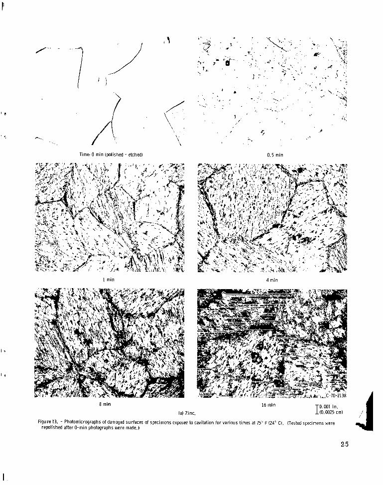
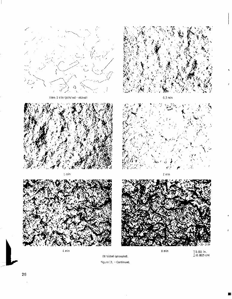
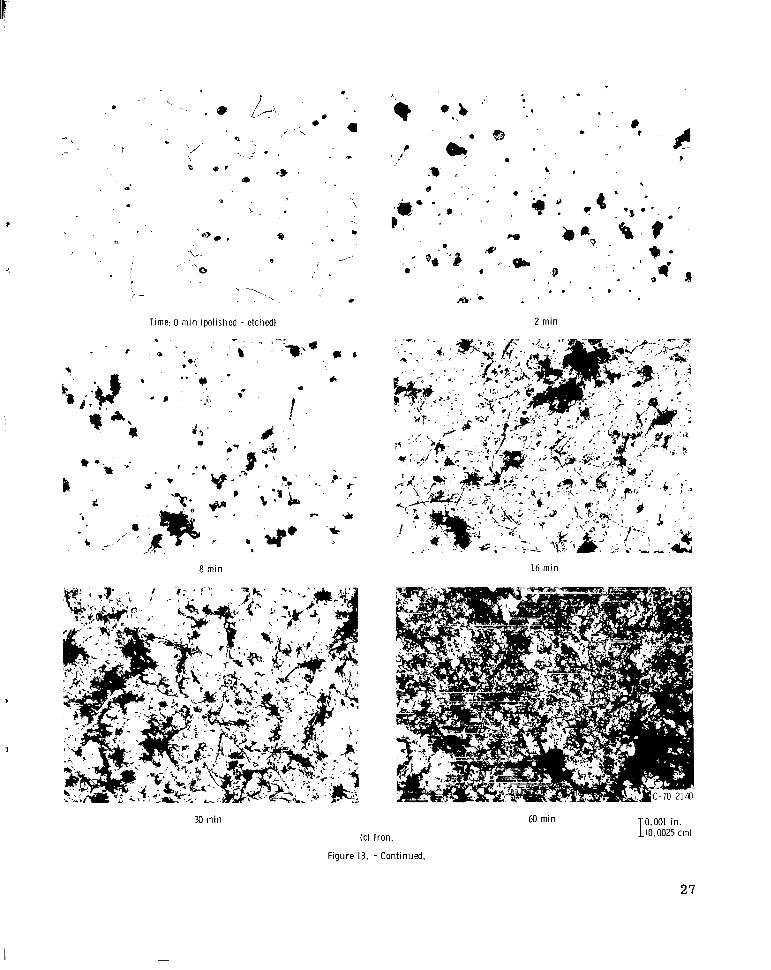
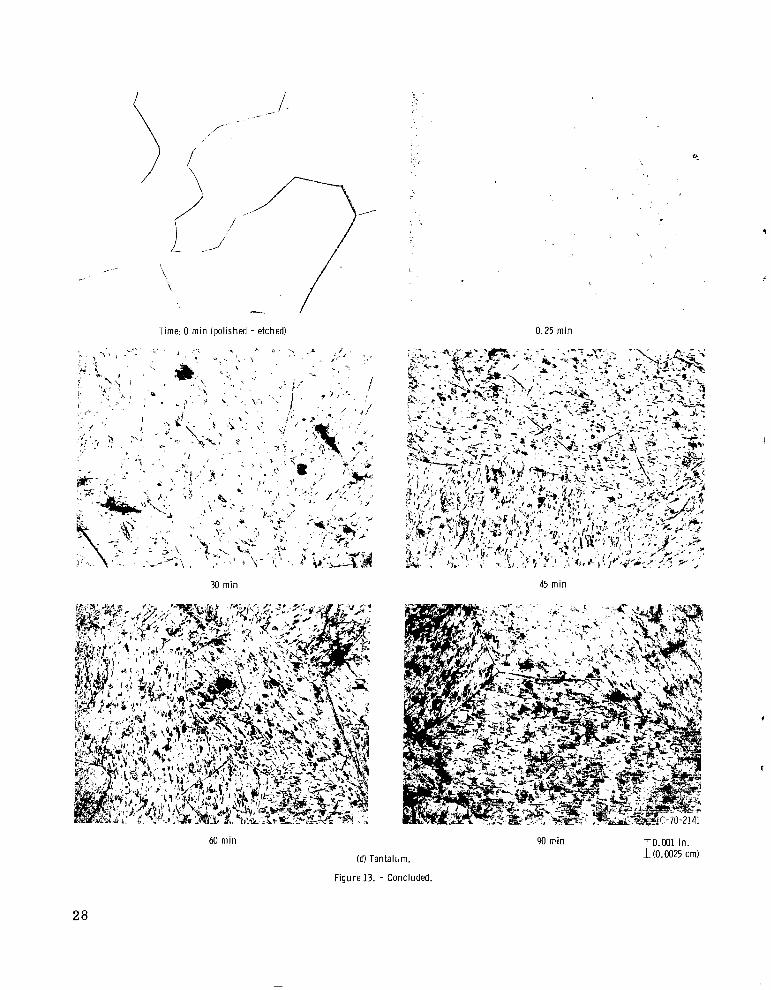
Effect ~ . _ _ of .- cavitation damage on metal structure. - Photomicrographs of the damaged surface of the unalloyed metals during early stages of cavitation damage a r e shown in figure 13. Each material w a s etched after polishing to obtain the micrograph of the un- tested material in the upper left of each figure. It w a s repolished before commencing the cavitation exposure.
In the early stages of damage, zinc, which is hexagonal close packed (hcp), showed parallel striations in one direction in each grain (fig. 13(a)). These may be t races of the basal (000 1) plane revealed by mechanical etching.
The damaged surfaces of the materials compared at a separation distance of 0.015
These tended to widen with in-
The other polished specimen w a s covered with 100 mesh particles of aluminum This specimen is
The photograph on the upper right shows that the specimen without The photograph
Similar striations were observed
7

by previous investigators (ref. - 6) after chemically etching a single crystal of zinc cleaved on a twinning plane (1012). After extended cavitation damage, individual grains of zinc were removed and cleaved faces were observed.
The face-centered cubic (fcc) nickel specimens were relatively fine grained and had a number of annealing twins. This soft material w a s rapidly damaged, and after only 0. 5 minute (fig. 13(b)) linear features which were probably due to the presence of annealing twins were barely discernible. At longer t imes the surface exhibited the "hills and valleys" pattern reported to be characterist ic of soft nickel (ref. 6).
On a macro scale the body-centered cubic (bcc) iron specimens were s imilar in appearance to the fcc nickel specimens (figs. l l (d) and (c), respectively). However, on a micro scale, grain boundaries of the iron specimens (fig. 13(c)) were evident up to 30 minutes exposure. The pits and inclusions evident in the as-polished specimen tended to widen as cavitation damage progressed.
Tantalum (bcc structure) on both a macro and micro scale exhibited its grain struc- ture in the early stages of damage. Boundaries were still evident in the tantalum speci- men even after 90 minutes cavitation (fig. 13(d)). Although no inclusions or voids were evident in the polished and etched specimen, cavitation formed pits similar to those ob- served in the iron specimen. At longer test t imes the pits widened and joined with small linear damage features in the matrix.
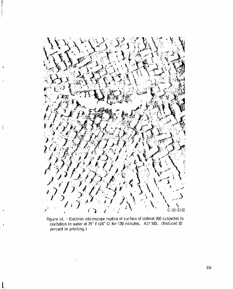
plex alloy such as Udimet 700. microstructure showing features typical of a gamma prime strengthened superalloy. It w a s mechanically etched by 120 minutes exposure to cavitation.
In view of the previous findings, that is, preferential damage of unalloyed metals and mechanical etching of a nickel-base alloy, it is conceivable that cavitation may be useful as a technique for selective etching of materials. The weaker phases would be removed, leaving the tougher, harder, impact resistant phases. This method would a l so allow the investigator to easily recover material from the distilled water (or any other fluid desired) for further analysis without the disadvantages associated with the use of reactive chemicals.
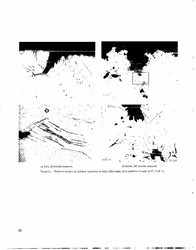
Comparison of cavitation damage characterist ics - - in water and sodium. - At the end of each test the unalloyed metals were sectioned axially, mounted, polished, and etched. Photomicrographs of the sectioned specimens a r e shown in figure 15. The predominant feature of cavitation damage observed in all specimens w a s undercutting; a lso some subsurface deformation w a s noted. Parallel subsurface cracks were observed in the zinc, and a deformation zone indicated by a loss of grain structure to a depth of -0.01 millimeter w a s noted in nickel. Transgranular cracking w a s a lso observed in zinc and iron. These damage characterist ics were observed previously in studies of cavitation damage to alloys in liquid metals (ref. 7). This similarity in damage characterist ics
Cavitation appears to be effective in revealing microstructural features of a com- Figure 14 is a replica electron micrograph of such a
% . . . . . . - . . . . . . . . . . . . -.
8
of materials in water and sodium lends further credence to the view that cavitation dam- age in the ultrasonic vibratory tests is primarily mechanical in nature.
SUMMARY OF RESULTS
Specimens of several unalloyed metals (zinc, nickel, iron, and tantalum) and Udimet 700 were subjected to cavitation damage in water using a vibratory apparatus under conditions which were with one exception those established for ear l ier ASTM round-robin tests. In the present investigation the specimens were stationary instead of being vibrated and were placed beneath an ultrasonically vibrated head. ing resul ts were obtained:
proximately 400 minutes of testing w a s zinc, annealed nickel 270 (Ni-270), iron, as- received Ni-270, tantalum, and Udimet 700. The volume loss of zinc and Udimet 700 were displaced by three orders of magnitude.
2. Surface roughness measurements clearly ranked the materials in the same order with regard to damage as shown by the volume loss measurements.
3. For as-received Ni-270, the one material tested at various separation distances between the specimen and vibrating head, a distance of 0.015 inch (0.038 cm) gave both the most constant damage rate over the longest period of time and the highest damage for the total length of the test.
4. In general, damage to stationary specimens of as-received Ni-270 w a s less than 50 percent of that observed with vibrating specimens of this same material in the ASTM round robin.
5. When abrasive particles of aluminum oxide and carbides were intentionally
The follow-
1. The relative ranking of materials, in order of decreasing volume loss after ap-
placed between the vibrating head and a stationary specimen, increased damage w a s ob- served at the center of the specimen; however, no preferred damage such as this w a s observed when no abrasives were added. dislodged during normal cavitation testing a r e probably ejected by the cavitating cloud and do not contribute further to specimen damage.
6. Preferential damage observed in unalloyed metals and Udimet 700 in distilled water indicates that cavitation may be useful as a technique for mechanically etching materials in certain situations where reactive chemicals would be undesirable.
showed that cavitation damage w a s characterized by undercutting, transgranular crack-
This result suggests that any metal particles
7 . Metallographic examination of specimen c ross sections of the unalloyed metals
9
ing, and subsurface deformation. The same damage characterist ics were observed earlier in steels and superalloys subjected t o cavitation damage in sodium.
Lewis Research Center, National Aeronautics and Space Administration,
Cleveland, Ohio, June 25, 1970, 129-03.
REFERENCES
1. Heymann, F. J. : Erosion by Cavitation, Liquid Impingement, and Solid Impingement. A Review. Rep. E-1460, Westinghouse Electric Corp. , Mar. 15, 1968.
2. Chao, C.; Hammitt, F. G. ; King, C. L. ; and Rogers, D. 0. : ASTM Round Robin Test with Vibratory Cavitation and Liquid Impact Facilities of 6061-T 6511 Alum- inum Alloy, 316 Stainless Steel, Commercially P u r e Nickel. Rep. MMPP-344-3-T, 01357-4-T, Univ. Michigan, Nov. 1968.
3. Young, Stanley G. : Cavitation Damage of Stainless Steel, Nickel, and an Aluminum Alloy in Water for ASTM Round Robin Tests. NASA TM X-1670, 1968.
4. Brager, D.; Cheesewright, R.; Hammitt, F. G. ; and Kemppainen, D. J.: Cavita- tion Erosion of a Stationary Specimen in Close Proximity to an Oscillating Surface. Rep. TR-08153-4-T, Univ. Michigan, May 1967. 816260. )
(Available from DDC as AD-
5. Young, S . G. ; and Johnston, J. R. : Accelerated Cavitation Damage of Steels and Superalloys in Sodium and Mercury. Tech. Publ. 408, ASTM, 1967, pp. 186-212.
Erosion by Cavitation or Impingement. Spec.
6. Plesset, M. S. ; and Ellis, A. T. : On the Mechanism of Cavitation Damage. Trans. ASME, vol. 77, no. 7, Oct. 1955, pp. 1055-1064.
7. Young, Stanley G. ; and Johnston, J ames R. : Effect of Cover Gas Pressures on Ac- celerated Cavitation Damage in Sodium. NASA TN D-4235, 1967.
10
=-I. 111 1.11.-11.- 1 1 1 1 1 1 1 1.1111.. I I I 1 -1- I
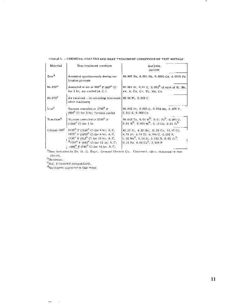
TABLE I. - CHEMICAL ANALYSIS AND HEAT TREATMENT CONDITIONS OF TEST METALS ~
Analysis, percent
99.997 Zn, 0 .001 Pb , 0.0005 Cd, 0.0015 F e
99 .981 Ni, 0. 0 1 C, O . O O l b of each of Si. Mn, Fe. S. Cu, C r . T i , Mg, C o
99.98 Ni, 0.005 C
99 .842 Fe , 0 .025 C. 0 .054 Mn, 0.006 P. 0. 011 S. 0.062 Cu
99 .845 T a , 0 . 0 1 Wb, 0 . 0 1 Feb, 0 , 0 0 1 C . 0 . 0 1 Sib. 0 .005 Nib. 0. 10 Cb. 0.01 Tib
42. 33 NI. 4. 32 Mo. 15. 55 Co, 14. 47 C r . 4. 28 Al. 3. 18 T I , 0. 104 C. 0.002 S,
0. 0 2 Mnb, 0 .04 SI. 0. 012 B. 0 . 02 %rb, 0 . 31 Fe. 0.02 Cub, 0. 004 P
Mater ia l
Zinca
Ni-270a
Ni-270'
Iron"
Tantaluma
udiniet -700"
Heat t rea tment condition
Annealed spontaneously during ex- t rus ion p r o c e s s
Annealed in a i r a t 900' F (482' C) f o r 1 hr; a i r cooled (A. C . )
A s rece ived - no annealing t rea tment a f t e r niach ining
Vacuum annealed a t 1750' F (954' C) for 3 hr; furnace cooled
~ a c u u i i i annealed at 2350' F (1288' C) for I Iir
2135" F (1168' C) for 4 hr ; A.C. 1975" F (1079' C) for 4 hr ; A. C. 1550" F (843' C) for 1 2 hr; A . C. d1550" F (843' C) f o r 1 2 hr: A . C. 140LF (760' C) f o r 16 .. hr; A.C.
"Data furnishrcl b y Dr . 0. G. Engel. Gcnera l Elec t r ic C o . , Cincinnati. Ohio. (ana lys i s b y SUI) -
p l t r r s ) . " M , x i ~ l u m . "Rcf. 3 (nominal composition). dSpccimens tnactiined at th i s stage.
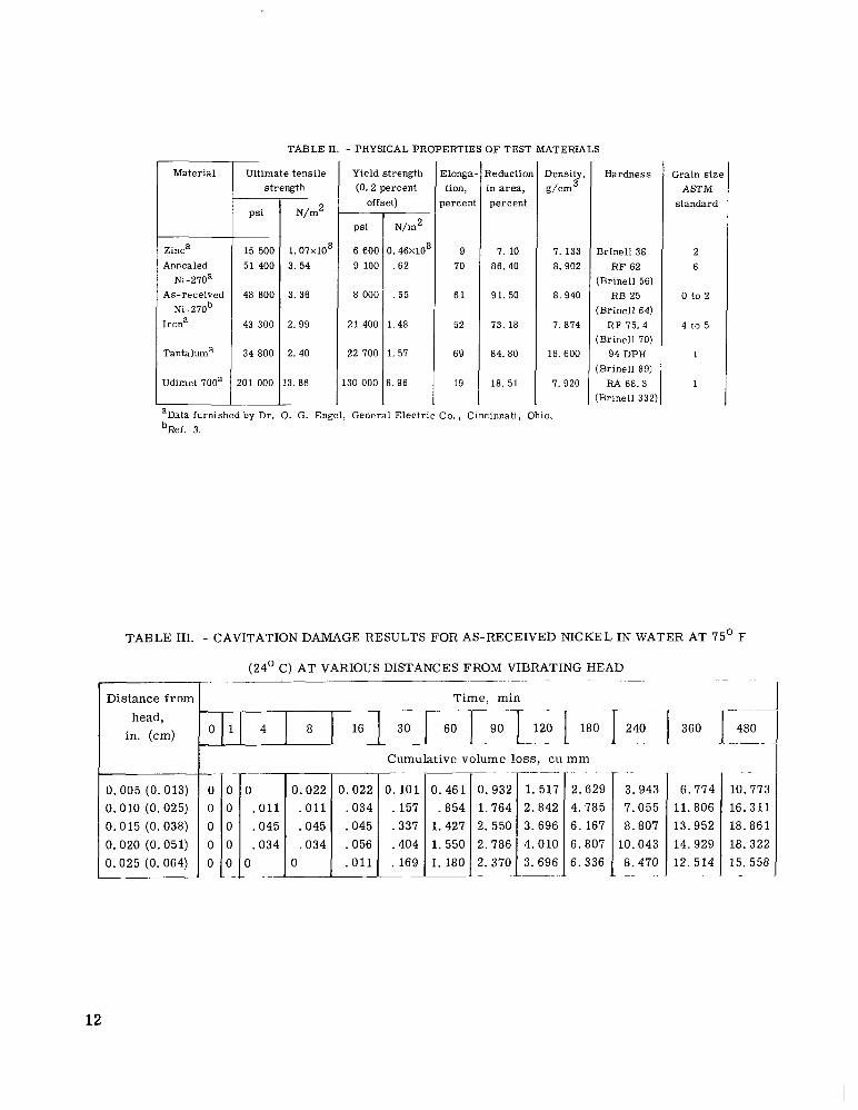
TABLE 11. - PHYSICAL PROPERTIES OF TEST MATERIALS
_.
-
Ultimate tens i le s t rength
Yield strength (0.2 percent
offset)
Elonga- tion,
Iercent
9 70
6 1
52
69
19
?eduction in a r e a , percent
7. 10 86.40
91. 50
73. 18
84.80
18. 51
Density,
g/cm3
7. 133 8.902
8.940
7.874
16.600
7.920
Hardness
Br ine l l 38 R F 62
(Br ine l l 56) RB 25
(Br ine l l 64) R F 75.4
(Br ine l l 70) 94 DPH
(Br ine l l 89) RA 68.3
(Br ine l l 332)
Grain sizi ASTM
standard
2 6
0 to 2
4 to 5
1
1
Mater ia l
- p s i
__ 15 500 51 400
48 800
43 300
34 800
101 000
N/m2
1.07x10⁸ 3. 54
3. 36
2. 99
2. 40
3. 86
~
psi
6 600 9 100
8 000
21 400
22 700
30 000
N/m2
3. 46X108
.62
.55
1. 48
1. 57
3 . 96
Zinca Annealed
Ni-270a As-received
Ni-270b [rona
Tantaluma
Udimet 700a
'Data 'Ref.
furnished 3.
Dr. ). G. Engel, General Elec t r ic C o . , Cincinnati, Ohio.
TABLE 111. - CAVITATION DAMAGE RESULTS FOR AS-RECEIVED NICKEL IN WATER AT 75' F
Distance from head,
in. (cm)
Cumulative volume loss, cu m m __
0.022 . O l l .045 .034
0 __
- ..
3.943 7.055 8.807
10.043 8.470
- _ _ .
. -
10.772 16.311 18.861 18.322 15.558
D. 005 (0.013) 3.010 (0.025) 3.015 (0.038) 3. 020 (0.051) 3.025 (0. 064)
0 . O l l . 045 .034
0 ~~
6.774 11.806 13.952 14.929 12. 514
0.022 .034 .045 .056 . 0 1 1
0 0
0 0 0
12
II I
TABLE IV. - SUMMARY OF CAVITATION DAMAGE (VOLUME L o s s )
DATA FOR MATERIALS IN WATER AT 75’ F (24’ C) A T CONSTANT
DISTANCE FROM HEAD OF 0.015 INCH (0.038 c m )
Tantaluma
rime, min
0 .25 .50 1 2
4 8 16 30 45
60 90
120 150 180
2 10 ? 40 300 360 120
180 5 40 $00 560 720 780 3 40
~ -
Volume loss, cu mm
I ,006 .012 .012 .012 .012
,012 ,048 .078 . 120 .458
. 952 1.153 3.602 5.735 8.241
10.813 13.464 16. 181 18.331 21. 127 23. 506 25.874
Zinc la
Time, min
0 .25 . 50 1 2 4 8
16 30 45
Volume loss, cu mm
0 0 0 .098 . 112 . 112 . 168
.463 18.477 43.931
Time, min
0 .25 . 50 1 2
4 8 16 30 45
60 90 120 150 180
2 10 240 300 360. 420
480 540 600 660 120 780 840 _______
Irona
‘olume loss cu mm
i .025 .025 .025 ,038 . 114
,261 .762 1.600 2. 515 3. 569
4.597 5.893 8.814 12.967 18. 136
23. 139 26.099 28.321 30. 163 32. 423 34.049 35.725
Zinc zb Time,
min
0 2 8 16 20 25 30
35 40 45 60 75 90 105 _______
Volume 10s cu mm
0 0
~
. 813 4.374 7.935 19.375 33.871
49. 180 65.835 85.238 136. 857 176.938 211.594 233. 128
Annealed nickela ~ . ~~
r i m e , min
0 .25 .50 1 2
4 8 16 30 45
60 75 90 120 150
180 2 10 240 300 360
420 480 540 600 660 720
~
~
Volume loss, c u mm
1 .045 . 124 .483 1.101
1.696 2.404 3.089 5. 179 7.212
9.335 11.245 13.143 16.457 19.148
22.826 26.219 28.376 30.813 33.891 36. 520
Udimet-700c aged _______
Time, min
0 120 180 240 300 420 540
660 I80 900 1020 1140
_______
~
Volume loss, cu m m
0 .139 . 177 ,202 ,354 .6 19 ,809
1.074 1. 314 1.529 1.680 2.046
aDiameter , 0. 562 in. (1. 43 cm). bDiameter, 1. 25 in. (3. 18 em). ‘Diameter, 1 in. (2. 54 em).
13
1111 1111 I I1111 I l l I I I 111 I 111111111
= Power ampl i f ie r -
". - 'Magnetostrictive t r a n d u c e r
Oscilloscope Magnetic
4 p ickup
C o u n t e r 1 I I ,,,,,-Thermometer V i b r at i ng rod - - - _ _
Level adjustment
Pos i t ion ing tab le - - * 7
Constan t tempera ture water circulator,
F igure 1. - Schematic diagram of cavitat ion test apparatus w i t h stat ionary specimen.
,,Vibrating rod y - y '
Adjustable distance---- -,-j. - - -Spec imen
- = , ' I -{-----;Specimen holder
Metal b a s e - . , , , r l 1 _- 7 0-ri ngs
t---- I I I
F igure 2. - Cavitat ion specimen ho lder assembly.
14
I Diam, I
(a) Z i n c 1 and tantalum. (b) I r o n and nickel.
,-Test face (polished) ,-Test face (polished) ,
(c) Z i n c 2. (d) Udimet 700.
F igure 3. - Ver t ica l c ross sections of i o u r d i f ferent types of cavitat ion test specimens used. ( A l l d imens ions are in inches (cm).)
Distance f rom head.
_ _ Vibrated specimens (ref. 3)
Stationary speci- / mens /
in. (cm) 0. 015 (0. 038)
-
/ /
Time, m i n
F i g u r e 4. - Comparisons of cavitat ion damage to vibrated and stat ionary specimens of as-received Ni-270 i n water at 75" F (24 C).
1 5
Time, m i n
20
16 E E
2 12 VI u) 0 - E 8
s - 4
0 .005 ,010 .015 ,020 ,025 Distance f rom head, in.
I I 0 ,025 .05
F i g u r e 5. - Effect of separation distance o n cavitat ion damage (vo lume loss) to as-received Ni-270 in water at 75" F (24" C ) at var ious test times.
Distance f rom head, cm
E E - VI
I E I
VI w, aJ c
3 0 m
Distance f r o m head (stat ionary specimens),
in. (cm)
0 100 200 300 400 500 Time, m i n
F i g u r e 6. - Sur face roughness of as-received Ni-270 sub- jected to cavitat ion damage i n water at 75 ' (24' C ) at v a r i - ous distances f rom v ib ra t ing head.
16
tfZinc
Time, m i n
F igu re 7. - Cavitat ion damage (vo lume loss) of metals in water at 75 F (24' C).
17
c .- E E E
\
3 V
c m I
VI VI 0 -
10
Z i n c
1
I r o n
ky5, Udimet 700
0 200 400 600 800
U
1000 1200 001
Time, m i n
F igu re 8. - Cavitat ion damage rate cu rves fo r metals in water at 75 F (24 C).
18
rl ir
t
.055
.05 .c
.015 E E - VI
E - m L n a,
c r m
2 . o L
a, U m L 3
LA
-
. 00'
2000 loo LBI " 600
500
400
300
200
100
0 100 200 300 400 500 50 Time, m i n
F i g u r e 9. - Sur face roughness of mater ia ls subjected to cavita t i o n damage in vjater at 75 F 124 C1.
19
I

r------.
f .
8”
Time: 4 min
(a) Distance from head, 0.025 inch (0.064 cm).
(b) Distance from head, 0.020 inch (0.051 cm).
(c) Distance from head, 0.015 inch (0.038 cm).
(d) Distance from head, 0.010 inch (0.025 cm).
M min 120 min
(e) Distance from head, 0.005 inch (0.013 cm).
480 min
$ i
?
Figure 10. - Damaged surfaces of as-received Ni-270 specimens after exposure i n water at 75’ F (24” C) for various times and distances from head.
20
* " ' . . j
i > ..., , ,.
8 min
Time: 8 niin
5 min
16 mln
1 min
30 1'1 in
( a i Zinc: 0.562-inch- 1143-cm-I t l idi i ieler r p r c i m w
16 min U, icin
tb) Zinc: 1.25-inch- (3.18-cin-I rlidrieier specimen.
4 min
Figure 11. - Damaged surfaces of specimens after exposure to cavitation i n 75" F (24" C) Water for Various times at separation distance of 0.015 inch (0.038 cm).
21

Time .25 min 8 min
90 min
Time 2 min
360 min
150 min
15 min
360 min
(c) Nickel (annealed).
." "
16 min 45 min
. .
420 min 600 min (d) Iron.
Figure 11. - Continued.
60 min r
720 min 0.1 in. (0.25 cm) I
210 min
22
Time: 2 5 min
300 min
Time: I20 min
90 min
420 min
120 min
6(K1 min
(e) Tantalum.
280 min 240 min
180 min
540 min
900 min 660 min 780 min
( f ) Udimet 700.
Figure 11. -Concluded-
23
(a) Untested pol ished specimen w i t h o u t part icles. (b) 8 M i n u t e s n o r m a l exposure.
(c) Untested pol ished specimen covered w i t h part icles. (d) 8 M i n u t e s exposure showing damage caused by part icles.
F i g u r e 12. - Effect of 100 mesh abras ive part icles o n cav i ta t ion damage to AIS1 type 316 s ta in less steel specimen in water at 75" F (24" 0.
31
I
24
T i m e 0 m i n (pol ished - etched)
1 m i n
8 m i n
c
0.5 m i n
4 m i n
16 m i n TO.OO1 in. 110.0025 cm) (a) Zinc.
Figure 13. - Photomicrographs of damaged surfaces of specimens exposed to cavitation for various times at 75' F (24" C). (Tested specimens were repolished after 0 -min photographs were made.)
25
I
Time: 0 m i n (pol ished - etched) 0.5 m i n
1 m i n 2 m i n
4 m i n
(b) Nickel (annealed).
F igure 13. - Continued.
0.001 in. I (0.0025 cm) 8 m i n
26
?
O . * . . . A. (L , . .~. ' i --..
0 - _
, . . .
Time: 0 min (polished - etched) 2 min
t
8 i ,
f .i
s v .3.
I . r .
. F- *-
I
3, '* 8 min 16 min
1
u) min
( c ) Iron.
Figure 13. - Continued.
0.001 in. I (0.0025 cm)
60 min
27
-_ Time: 0 m i n (pol ished - etched) 0.25 m i n
u) m i n 45 m i n
60 m i n
Id) Tantalum.
F igure 13. - Concluded.
0.001 in. I (0.0025 cm) 90 m i n
28
1
Figure 14. - Electron microscope replica of surface of Udimet 700 subjected to cavitation in water at 75" F (24" C) for 120 minutes. X17 500. (Reduced 30 percent in pr int ing.)
29
I.
f
& . * * .
4
(a) Z i n c ; 45 minutes exposure.
F igure 15. - Photomicrographs of sectioned specimens of metals after exposure to cavitat ion in water at 75' F (24' C )
(b) Nickel; 720 minutes exposure.
I
30
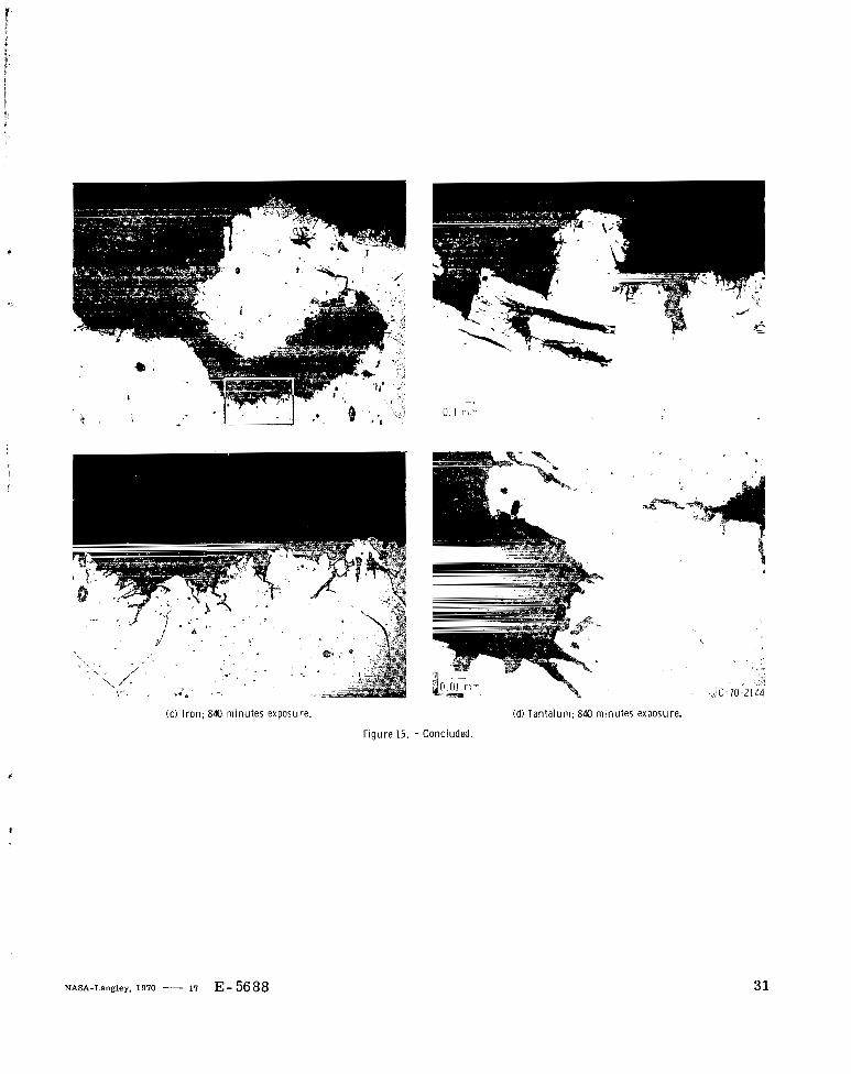
( c ) I ron; 840 minutes exposure. (d) Tantalum; 840 m i n i
'
utes exposure.
F igure 15. - Concluded.
NASA-Langley, 1970 - 17 E- 5688 31
I mll11l1ll !
NATIONAL AERONAUTICS AND SPACE ADMINISTRATION WASHINGTON, D. C. 20546
OFFICIAL BUSINESS FIRST CLASS MAIL
12
"The arsonnittical a i d space nctii'ities of the Uizited Strifes shall be coizdncted so cis t o coiztribiitr . . . t o the expmisioia of h/i~icciz knorul- edge of pheuoiiieua iiz the atniosphese and space. The Administrcctioii shall pro ride fo r the widest prdctirLzble alzd appropsiate disse))ziiaation of iiifosui'itioii coiireriziizg its nctiz'itjes a i d the r e s d t s theseof."
-NATIONAL AERONAUTICS AND SPACE ACT OF 1958
NASA SCIENTIFIC AND TECHNICAL PUBLICATIONS
TECHNICAL REPORTS: Scientific and technical information considered important, complete, and a lasting contribution to existing knowledge.
TECHNICAL NOTES: Information less broad in scope but nevertheless of importance as a contribution to existing knowledge.
TECHNICAL MEMORANDUMS: Information receiving limited distribution because of preliminary data, security classifica-
_ . . .
TECHNICAL TRANSLATIONS: Information published in a foreign language considered to megt NASA distribution in English.
SPECIAL PUBLICATIONS: Information derived from or of value to NASA activides. Publications include conference proceedings, monographs, data compilations, handbooks, sourcebooks, and special bibliographies.
TECHNOLOGY UTILIZATION PUBLICATIONS: Information on technology
tion, or other reasons.
CONTRACTOR REPORTS: Scientific and technical information generated under a NASA contract or grant and considered an important contribution to existing knowledge.
iised by NASA that may be of particular interest in commercial and other non-aerospace npplications. Publications include Tech Briefs, ~ c c h n o l o g y Uti~iZdtioIl Reports and Notes, and Technology Surveys.
Details on the availability of these publications may be obtained from:
SCIENTIFIC AND TECHNICAL INFORMATION DIVISION
NATIONAL AERONAUTICS AND SPACE ADMINISTRATION Washington, D.C. 20546