Embed Size (px)
Citation preview

American Institute of Aeronautics and Astronautics
1
Structural Sizing Methodology for the Tendon-Actuated
Lightweight In-Space MANipulator (TALISMAN) System
Thomas C. Jones1, John T. Dorsey
2 and William R. Doggett
3
NASA Langley Research Center, Hampton, VA, 23681
The Tendon-Actuated Lightweight In-Space MANipulator (TALISMAN) is a versatile
long-reach robotic manipulator that is currently being tested at NASA Langley Research
Center. TALISMAN is designed to be highly mass-efficient and multi-mission capable, with
applications including asteroid retrieval and manipulation, in-space servicing, and astronaut
and payload positioning. The manipulator uses a modular, periodic, tension-compression
design that lends itself well to analytical modeling. Given the versatility of application for
TALISMAN, a structural sizing methodology was developed that could rapidly assess mass
and configuration sensitivities for any specified operating work space, applied loads and
mission requirements. This methodology allows the systematic sizing of the key structural
members of TALISMAN, which include the truss arm links, the spreaders and the tension
elements. This paper summarizes the detailed analytical derivations and methodology that
support the structural sizing approach and provides results from some recent TALISMAN
designs developed for current and proposed mission architectures.
Nomenclature
A = cross-sectional area
a = width of truss link and I-beam spreader webbing
ARM = Asteroid Redirect Mission
ARV = Asteroid Retrieval Vehicle
B = buckling coefficient (end fixity)
Cw = warping stiffness
COTS = Commercial Off-The-Shelf
Dn = principle diameters of boulder
dt = tab width on cutout webbing of open-section I-beam
δp = percent deflection
δy = tip deflection
E = modulus of elasticity
EVA = Extra-Vehicular Activity
F = internal member load
Fkl = kick load
Fx, Fy, Fz = applied tip loads in the principle directions
G = shear modulus
h = total height of spreader
hcs = height of closed-section side of spreader
hos = height of open-section side of spreader
Io = polar area moment of inertia
I = area moment of inertia
J = Jacobian Matrix
J+
= Pseudo-Inverse Jacobian
L = length of a structural member
Lbend = length of moment arm in bending
Llink = length of a single link
1 Research Engineer, Structural Mechanics and Concepts Branch, MS 190, Member, AIAA.
2 Senior Research Engineer, Structural Mechanics and Concepts Branch, MS 190, Associate Fellow, AIAA.
3 Senior Research Engineer, Structural Mechanics and Concepts Branch, MS 190, Associate Fellow, AIAA.
https://ntrs.nasa.gov/search.jsp?R=20160006316 2018-07-05T18:01:41+00:00Z
American Institute of Aeronautics and Astronautics
2
Ltors = length of moment arm in torsion
Ltotal = total length of TALISMAN
LaRC = Langley Research Center
LSMS = Lightweight Surface Manipulation System
M = mass
MT
Mx, My, Mz
= metric ton
= moments about the principle axes
MATLAB = MATrix LABoratory (software suite)
OA = obstacle avoidance
Pcr = critical buckling load
R = radius of tendon
(SF)b = safety factor on buckling
(SF)s = safety factor on strength
T = applied torque
TALISMAN = Tendon-Actuated Lightweight In-Space MANipulator
t = wall thickness
W = flange width or tendon webbing width
Ẋ = nodal velocities
z = vector of arbitrary joint velocities
α = truss link bay length / width ratio
γ = truss link bay depth / width ratio
σs = ultimate stress
θi = joint angles
�̇� = joint velocities
I. Introduction
ASA Langley Research (LaRC) Center has been studying long-reach, tendon-actuated manipulators for a
decade. During the constellation program (2005-2009), there was a need for a versatile, dexterous manipulator
that could offload payloads from the Altair lunar lander and that could also perform additional tasks on the lunar
surface1. The Lightweight Surface Manipulation System (LSMS) was designed to meet these needs (Fig. 1a) and
provided a highly mass-efficient approach to performing multiple tasks including payload positioning, digging, fork-
lift operations, grappling and precision welding1, 2
. The modular, periodic, tension-compression design of the LSMS
provides several benefits that have been incorporated into the latest generation, Tendon-Actuated Lightweight In-
Space MANipulator (TALISMAN). These benefits include the mechanical advantage provided by the spreaders that
offset the tension elements at the joints, reducing the required motor size and providing geometric stiffness in the
plane of the spreaders; and the simplicity of the structural design that allows rapid analytical modeling and sizing.
TALISMAN, like the LSMS, provides multi-mission capabilities, with applications including asteroid retrieval and
N
a) LSMS during field testing at Moses Lakes, WA. b) TALISMAN prototypes at NASA LaRC.
Figure 1. Long-reach manipulators developed at NASA LaRC.
American Institute of Aeronautics and Astronautics
3
manipulation, in-space servicing, and astronaut and payload positioning3-5
. Given this mission versatility, a
structural sizing methodology was developed to rapidly assess mass and configuration sensitivities for any specified
operational work space, applied loads and mission requirements. This methodology allows the systematic sizing of
the three sets of TALISMAN primary structural members (Fig. 1b), which include the truss arm links, the spreaders
and the tendons (tension elements). This analysis capability allows TALISMAN designs to be integrated into
mission architecture trade studies that are ongoing at NASA and provides the initial design sizing for more detailed
dynamics6, 7
and controls8 studies being performed within the TALISMAN research team. This paper details the
implementation of the structural sizing methodology in a custom code written in MATLAB, and provides results
from a recent design of multiple TALISMANs envisioned for use on the Asteroid Redirect Mission (ARM) Concept
B. Derivations of the sizing equations are provided in the Appendix.
II. Structural Sizing Methodology
Initially, closed-form, parametric equations were derived for sizing the three primary sets of structural members
for TALISMAN and were used in a rapid-design spreadsheet described in Doggett et al3. This spreadsheet-based
design tool produced conservative structural mass estimates and sizing for a fully-extended TALISMAN, subject to
in-plane tip loads, where the design used the same member geometry for each set of arm links, spreaders and
tendons throughout. However, the closed-form equations did not include axial tip loads, and only the maximum
resultant loads in each set of primary structural members were used for sizing. Recent mission analyses have
required a more comprehensive structural optimization approach that includes the ability to vary individual member
lengths; size members based on the individual member loads; include the effects of different manipulator poses; and
consider a well-defined and actively-controlled operational envelope to better specify the loading and stiffness
requirements. As a result, a new and more sophisticated design tool was created in MATLAB and is being used for
sizing and sensitivity analyses that are based on current NASA mission architectures and possible future
TALISMAN applications.
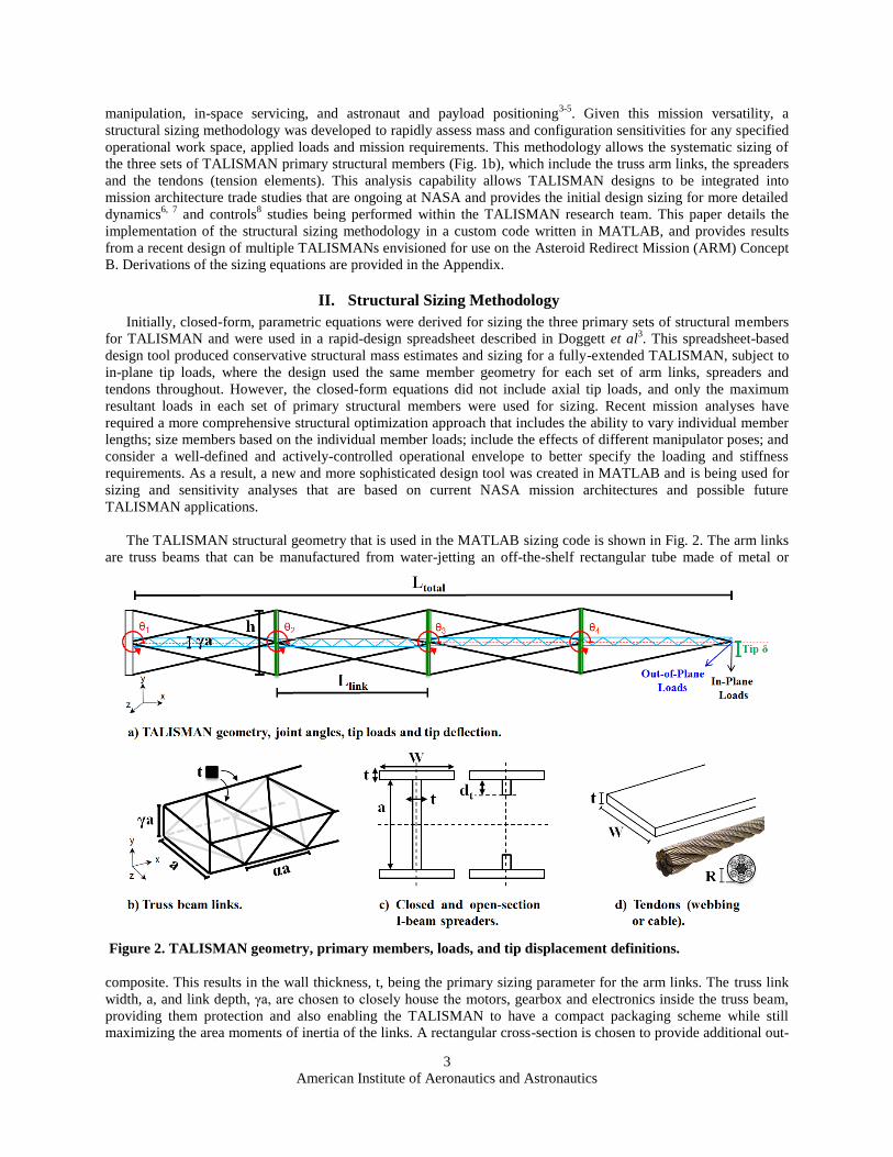
The TALISMAN structural geometry that is used in the MATLAB sizing code is shown in Fig. 2. The arm links
are truss beams that can be manufactured from water-jetting an off-the-shelf rectangular tube made of metal or
composite. This results in the wall thickness, t, being the primary sizing parameter for the arm links. The truss link
width, a, and link depth, γa, are chosen to closely house the motors, gearbox and electronics inside the truss beam,
providing them protection and also enabling the TALISMAN to have a compact packaging scheme while still
maximizing the area moments of inertia of the links. A rectangular cross-section is chosen to provide additional out-
Figure 2. TALISMAN geometry, primary members, loads, and tip displacement definitions.
American Institute of Aeronautics and Astronautics
4
of-plane stiffness, since the global stiffness in that direction is not aided by the spreaders. The truss links have an
additional sizing parameter, α, that defines the length of the local bays in each link. This parameter changes the
angles of the diagonals and allows optimization of the link torsional stiffness that may be required for out-of-plane
loads induced when the joint angles, θi, are non-zero. The spreaders are the vertical members attached at each joint,
and used in conjunction with the tendons, to provide mechanical advantage and in-plane stiffness. I-beams are used
for the spreaders to enable compact stowage alongside the arm links. Each spreader is composed of two cross-
sections; a standard, closed-section I-beam on one side of the link, and an open-section I-beam on the otherside
(with a large portion of the central webbing cut out from top to bottom). The open-section side allows the spreader
to be unlocked at the joint and driven in the direction of the closed section5, providing the ability to dynamically
alter the geometry of the TALISMAN for a specific operation, such as increasing the in-plane stiffness on that side.
In addition, a more compact packaged state can be achieved by retracting the spreaders. Since the packaging scheme
requires a Z-fold of the links, the open- and closed-section sides of the spreaders alternate at each adjacent joint
along the length of the TALISMAN to provide the most compact packaging. The spreaders are constrained to the
width of the truss links, a, however, the wall thickness, t, could be used as a sizing parameter, although it is also
partially constrained by the desire to maintain a compact joint. The flange width, W, is therefore used as the sizing
parameter, as its magnitude is only restricted by the link depth, γa, on each side. Finally, the tendons are cables in
the current, as-built hardware prototypes, but future variants of the TALISMAN may use composite webbings or
tapes for their increased stiffness and linearity. The sizing parameter is the cable radius, R, but since the sizing is
only based on the tensile strength, the sized area can be readily converted to a width and thickness of a candidate
webbing for future studies.
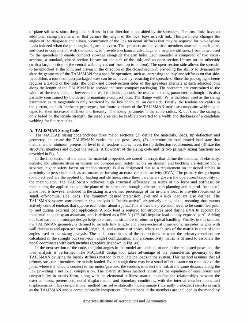
A. TALISMAN Sizing Code
The MATLAB sizing code includes three major sections: (1) define the materials, loads, tip deflection and
geometry, i.e. create the TALISMAN model and the pose cases, (2) determine the equilibrated load state that
maintains the minimum pretension level in all tendons and achieves the tip deflection requirement, and (3) size the
structural members and output the results. A flowchart of the sizing code and its two primary sizing functions are
provided in Fig. 3.
In the first section of the code, the material properties are stored in arrays that define the modulus of elasticity,
density, and ultimate stress in tension and compression. Safety factors on strength and buckling are defined and a
separate, higher safety factor on tendon strength is also designated due to a requirement on tensioned cables in
proximity to personnel, such as astronauts performing an extra-vehicular activity (EVA). The primary design inputs
(or objectives) are the applied tip loading and stiffness, since these parameters govern the operational capability of
the manipulator. The TALISMAN achieves high structural efficiency, in terms of tip force and stiffness, by
maintaining the applied loads in the plane of the spreaders through judicious path planning and control. An out-of-
plane load is however included in the sizing as a defined percentage of the in-plane load, to provide robustness to
small, off-nominal side loads. The minimum desired pretension level and a kick load are also defined. The
TALISMAN system considered in this analysis is “active-active”, or actively-antagonistic, meaning that motors
actively control tendons that oppose each other about a joint. This allows the pretension level to be controlled prior
to, and during, external load application. A kick load is required for structures used during EVA to account for
incidental contact by an astronaut, and is defined as a 556 N (125 lbf) impulse load on any exposed part9. Adding
this load case to a prototype design helps to ensure the structure is robust to typical handling. Finally, in this section,
the TALISMAN geometry is defined to include link lengths and cross-sectional dimensions; spreader heights with
wall thickness and open-section tab length, dt; and a matrix of poses, where each row of the matrix is a set of joint
angles used in the sizing analysis. The nodal coordinates of the connections between the primary members are
calculated in the straight out (zero-joint angle) configuration, and a connectivity matrix is defined to associate the
nodal coordinates with each member (graphically shown in Fig. 4a).
In the next section of the code, the joint angles in the model are updated to one of the requested poses and the
load analysis is performed. The MATLAB design tool takes advantage of the pinned-truss geometry of the
TALISMAN by using the matrix stiffness method to calculate the loads in the system. This method assumes that all
primary structural members are axially loaded. Even though there may be a small offset distance on each side of the
joint, where the tendons connect to the motor/gearbox, the tendons intersect the link at the same distance along the
link providing a net axial compression. The matrix stiffness method constructs the equations of equilibrium and
compatibility in matrix form, along with the elemental stiffness matrix, to define the relationships between the
external loads, pretensions, nodal displacements and boundary conditions, with the internal member loads and
displacements. This computational method can solve statically indeterminate (internally preloaded) structures such
as the TALISMAN and is computationally inexpensive. The preloads in the members are included in the model by
American Institute of Aeronautics and Astronautics
5
converting them, through the equilibrium matrix, to nodal forces that are added to the external nodal load vector.
Initially, the preloads are set to zero and the member loads are calculated with only external loads applied, which
results in some of the tendons going into compression. The tendons with the lowest loads associated with each link
(see Fig. 4 for definition of the member groups) are selected as the driving tendons for the pretension iterations, in
order to guarantee all tendons will achieve the minimum required preload after equilibrium. The initial pretensions
are set equal to the applied tip load in the first pretension iteration, after which they are updated by polynomial curve
Figure 3. TALISMAN sizing code and function flow charts.
Figure 4. Nodal coordinates and connectivity for a 4-link TALISMAN in a zero joint angle configuration.
(Colors represent structural members associated with each of the four links).

American Institute of Aeronautics and Astronautics
6
fitting of the initial and resultant preload data from each iteration. Once the model obtains an equilibrated load state,
where the minimum tendon load is met, the members are sized (as detailed below) and the tip displacement
requirement is checked. If the tip displacement does not meet the requirement, then the tendon radius is scaled in
proportion to the current tip displacement and the load and sizing calculations are performed again until the tip
displacement requirement is satisfied within a defined error bound.
The sizing section of the code is split into three functions that size the truss links, spreaders and tendons. The
derivations of the sizing equations used in these functions are included in the Appendix and a flow chart of the truss
link and spreader sizing functions are given in Fig. 3. The tendon sizing function is the simplest, as it only requires
checking the ultimate tensile strength to size the radius. However, as detailed in the previous section, iterations are
also performed (in the green loop A of Fig. 3) that adjust the radius to meet the global tip stiffness requirement. The
truss links are sized primarily by the local members that are produced from water-jetting a rectangular tube. These
local members are the longerons and diagonals of the truss link and have square cross-sections of side t (i.e. the wall
thickness of the link). The truss link sizing function receives the property data for the current link and its member
forces. If an out-of-plane load is specified, the bending and torsional moments, produced at the root of the link, are
calculated and included in the resultant loads for sizing. Buckling and strength equations are formulated for the
longerons and diagonals (Appendix) and the maximum wall thickness, t, is calculated along with the resulting truss
link mass. These equations are executed within an iterative loop that searches for the α (local truss bay length /
width ratio, Fig. 2) that produces the lowest link mass. The final values of t, α, cross-section area, mass and the
sizing failure criterion are returned to the main code. The spreader sizing function also receives the properties and
member loads, but is unaffected by any out-of-plane tip load for these initial sizing assumptions due to its location at
the joint. In theory, a large moment at the tip could impact the spreader locally, but the joint and links are likely to
fail first under such loading. Buckling and strength criteria are defined, for both the open- and closed-sections of the
spreader (Appendix) and the flange width, W, is sized for both sections. Since the spreader is a continuous member,
the maximum value of W, from both sides, is selected and used to calculate the spreader mass. The final values of
W, cross-section area, mass and the sizing failure criterion are then returned to the main code.
Sizing of the truss links and spreaders is only performed in the first iteration of the outer, tip displacement loop
(loop A in Fig. 3). This might seem counter-intuitive for a statically indeterminate structure, where a change in the
stiffness of the tendons could alter the loads, and hence the required sizing of the other members. However, due to
the pretension level being set in each iteration, and the applied loads remaining constant, the member loads also
remain constant throughout this loop. For each TALISMAN pose case, a data array is produced that stores
geometric, mass, and failure criterion data. After all pose cases are processed, the maximum member sizes are
selected from all analyzed cases and are output as the final design sizing from the code. This design meets all load
and displacement requirements across all pose cases.
B. TALISMAN Geometry / Link Sizing Code for ARM
The MATLAB sizing code described in Section II. A, takes the initial geometry of the links and spreaders as an
input. For a given TALISMAN design, the number and length of the links are chosen to provide both a desired reach
and operational workspace, i.e. dexterity within the reach envelope. Packaged volume may also be important for a
particular mission, thus more shorter links may be advantageous over fewer, longer links. The most recent design
study for which TALISMAN sizing was performed was for the Asteroid Redirect Mission (ARM) Concept B4. This
mission architecture employed three TALISMANs as grapple arms to pick up a boulder on the surface of a
100 m class asteroid, and three additional TALISMANs as landing legs to enable a soft touchdown on, and push-off
from, the asteroid. This mission architecture added a further series of constraints on the TALISMAN geometry and
workspace by requiring obstacle avoidance around the spacecraft, the boulder, and the surface of the asteroid. To
expedite the selection of link and spreader lengths for ARM-like architectures, an additional MATLAB code was
written to investigate and size the TALISMAN geometry required for grapple and landing operations. This code, to
define and plot the geometry, and its core joint angle configuration function is described by the flow charts in Fig. 5.
The TALISMAN ARM geometry code requires the user to input the dimensions of the Asteroid Retrieval
Vehicle (ARV) to which the TALISMAN grapple arms and landing legs are attached around the ARV hexagonal
baseplate. The boulder is defined as an ellipsoid, with principle axes (diameters) of lengths D1, D2, and D3.
Additional inputs include the current distance between the ARV baseplate and the asteroid surface (Fig. 6); the
buried depth of the boulder; the minimum clearance distance between the TALISMAN spreaders and the boulder;
and the tip contact point on the boulder for the grapple arms or on the surface for the landing legs. The three grapple
arms and three landing legs are run as two separate sizing cases. For the grapple arm case, each of the three
TALISMANs may have a unique set of joint angles if the radius (semi-major axis of the elliptical surface path) of
the tip contact point on the boulder is different for each, which depends on the dimensions of the boulder ellipsoid.

American Institute of Aeronautics and Astronautics
7
As all three grapple arms have to perform a coordinated grapple and retraction (or for the landing legs, an extension
and push-off), the tips of the TALISMANs in both cases trace a vertical path. Therefore, a final parameter defines
the tip location along that vertical motion path, as a percentage of the total distance it travels in each case,
simplifying the definition of the tip contact point for the user. Initial link and spreader lengths are defined and the
Figure 5. TALISMAN geometry code and joint angle function flow charts.
Figure 6. TALISMAN grapple arm geometry with key features and nodes highlighted.
American Institute of Aeronautics and Astronautics
8
ARV, boulder and surface plane are plotted in three-dimensions (3-D). Each of the three TALISMANs, for a given
mission design analysis, are equally spaced at 120 degrees around the base of the ARV. The grapple arms and
landing legs are adjacent to each other, 60 degrees apart. The actuation plane of each grapple arm is aligned with an
elliptical slice through the boulder. This elliptical surface path defines the set of viable grapple arm tip contact points
and is added to the 3-D plot for each arm. This ellipse is also used in the joint angle configuration function to define
the two-dimensional (2-D) shape of the boulder.
The joint angle function is called for each of the three TALISMANs in a set (either grapple arms or landing legs)
and includes the following inputs: the elliptical surface definition, the base node and tip contact coordinates, the
boulder buried depth, the slope at the boulder-tip contact point (for the grapple arms) and the minimum clearance
distance. This function was primarily written to adjust the joint angles of the grapple arms while following three
objectives: 1) place the tip at the desired contact point on the boulder; 2) avoid ancillary contact between the
TALISMAN and the ARV, boulder or surface; and 3) try to balance the joint angles to reduce the peak magnitude of
any one angle (i.e. eliminate kinks) and thus reduce peak loads in the TALISMAN. An example of a grapple arm
with balanced joint angles is shown in Fig. 6. Currently, a pseudoinverse kinematics approach is being explored to
iterate the joint angles, while also implementing forcing functions for obstacle avoidance and joint angle balancing,
as described in the robotics literature10, 11
. The pseudoinverse, J+, is a generalized inverse of the Jacobian, J, for
transforming nodal velocities, , into joint velocities, , in manipulators with redundant degrees of freedom. From
reference 10, where I is the identity matrix and z is an arbitrary vector of joint velocities:
(1)
The first part of Eq. 1 is the least squares solution to the redundant system of equations, and the second part is a
homogeneous solution that operates in the null space of the transformation. z can be produced by a forcing function
and projected, via the term in parentheses, into the null space. Several forcing terms can be included in this manner
that influence the joint angle iterations without hindering the primary goal of directing the tip to the desired contact
point. The obstacle avoidance (OA) forcing terms are written for three OA nodes (shown in Fig. 6) that make the
closest approaches to the ARV, boulder and asteroid surface. An OA term is only activated once the OA node comes
within a defined sphere of influence (SOI) of the obstacle with which the OA node is associated. The gain of the OA
term is then ramped up quadratically as the node approaches the obstacle until a maximum gain is reached at a
prescribed distance. These distances and gains can be varied in the code to adjust their influence on the joint angle
iterations. Soft joint limits are also prescribed, using a fourth forcing term that acts in a similar manner to the OA
terms, ramping quadratically to a maximum gain at the joint limits around a defined optimal angle. These limits are
classified as ‘soft’ as there is not a hard cutoff of the analysis at the joint limits, instead the specified maximum gain
would be exceeded. The optimal angles are defined as the set of balanced interior angles (Fig. 6) that place the tip at
the desired contact point given a fixed base point. If the obstacle constraints are met in this initial, balanced angle
configuration then no iteration is needed. If an obstacle constraint is violated then iterations are performed to
progress towards a more optimal joint angle solution. It is also possible that no solution exists, if the original link or
spreader dimensions were poorly chosen for the current boulder geometry. At each stage of the iteration cycle, a plot
like that shown on the right side of Fig. 6 is produced to display the progress of the optimization to the user. Once a
final set of joint angles are obtained, the angles and nodal coordinates are returned to the main geometry code.
The function is repeated for the other two TALISMANs and the final configurations are plotted in the original
3-D figure. The configuration results are stored to an output data file that can be referenced in the TALISMAN
sizing code as pose input data. When performing configuration analyses in which multiple different sized boulders
are to be retrievable by the capture system of grapple arms and landing legs, it is likely, that the initially chosen link
and spreader lengths will have to be updated and additional runs of the program performed to obtain a final
geometry for the arms and legs that satisfy all boulder cases (outer loop of TALISMAN ARM geometry code,
Fig. 5). The following section discusses results from a recent case study for the ARM Concept B that utilizes both
codes described in Section II to size sets of grapple arms and landing legs with the capability to retrieve a wide
range of different boulder sizes from an asteroid.
III. Results from ARM Concept B Mission Sizing for asteroid 2008 EV5
The ARM Concept B was selected in March 2015 as the focus for ongoing studies into a boulder retrieval and
return mission with a possible launch in late 2020. Several candidate 400 m+ diameter carbonaceous asteroids have
been identified as possible targets for such a mission including: Bennu, currently the target of the OSIRIS-Rex
X
zJJIXJ

American Institute of Aeronautics and Astronautics
9
sample return mission; 1999 JU3, the target of the Japanese Hayabusa 2 sample return mission; and 2008 EV5. 2008
EV5 is currently preferred in the NASA ARM Concept B studies
12 due to EV5 having been extensively observed
and characterized from ground-based infrared telescopes and radars (Fig. 7). The MATLAB codes described in
Section II were used to size three TALISMAN grapple arms and three TALISMAN landing legs for a conceptual
boulder retrieval mission to 2008 EV5. The key stages of the capture operation are shown in Fig. 8 for a previously
studied boulder retrieval mission to Phobos, using the same TALISMAN-based capture architecture. The current
baseline operations for the capture portion of the EV5 mission begin with the ARV at zero relative velocity to the
surface, 20 m above the center of the boulder. The ARV then uses the low gravity of EV5 to pull itself towards the
surface at a very slowly increasing velocity until the landing legs make contact. The landing legs then lower the
ARV toward the surface until the grapple arms can secure the boulder at three points. The grapple arms then retract
the boulder and secure it against the ARV, after which the landing legs push the ARV off the surface, reaching a
maximum velocity that, at a minimum, propels the ARV to a height of 50 m above the surface.
A. TALISMAN Geometry and Configuration
The ARM mission Concept B is focused on retrieving one boulder, 1 m to 5 m in diameter, with a maximum
mass of 70,000 Kg (70 metric tons [MT]) from the surface of 2008 EV5. The LaRC ARM study team defined ten
ellipsoid boulder geometries for study that encompassed a wide range of sizes (Fig. 9). These shapes provide a
baseline set of analysis cases that any capture system must be able to grapple and secure, and assist in the push-off
of the spacecraft and boulder from the asteroid surface. From a geometric sizing perspective, the links of the grapple
Figure 7. 2008 EV5 properties13, 14
and radar shape model from Ref. 14.
Figure 8. Artist’s concept of TALISMANs used as landing legs and grapple arms for a Phobos boulder
retrieval mission.

American Institute of Aeronautics and Astronautics
10
manipulators must be able to reach around any of the boulders and maintain tip contact throughout the grapple and
secure maneuver while avoiding any ancillary contact with the boulder, surface or ARV. The landing leg geometries
are not as constrained by the boulder geometry, but they must provide enough force and vertical stroke to launch the
full mass of the ARV and boulder to at least a height of 50 m above the surface. The launch height is stipulated in
the mission architecture to avoid having to use thrusters near the surface of the asteroid, which could cause
damaging dust particles to be ejected toward the spacecraft and solar arrays. A push-off stroke of 1 m was chosen
for the landing legs as a reasonable estimate (given the low gravity environment) over which to accelerate the ARV
and boulder to a velocity that could achieve the required 50 m height.
The boulder cases that drove the sizing were found to be the smallest boulder (1 m by 1 m by 1 m), and the two
largest boulders (5 m by 5 m by 2.5 m and 4 m by 4 m by 4 m). These three cases are all axisymmetric about the
vertical axis and thus only one set of poses was required for each set of grapple arms and landing legs. The mass of
the 1 m by 1 m by 1 m boulder is only 1 MT to 2 MT, but due to the requirement of using the same manipulator
geometry for all ten boulder sizes, retracting such a small boulder leads to a larger range of motion and more severe
joint angles which must be checked. For the two largest boulders (cases 9 and 10 in Table 1), the manipulators are
geometrically sized to achieve minimum clearances. The range in density of 2008 EV5 allows for a factor of 2
difference in mass for any given boulder volume. Due to the maximum payload limit of 70 MT for this mission, the
only way the two largest boulders could be retrieved would be if their densities were at most, approximately 2
g/cm3. For boulder cases 1 to 8, the density is assumed to be 4 g/cm
3 to be conservative.
The final sized link lengths for the grapple arms and landing legs, that met all constraints and boulder cases,
were determined to be 1.3 m and 1.6 m, respectively. 4-Link TALISMANs were used for both the grapple arms and
landing legs to provide greater dexterity for orienting the tip while performing the operations described. Although a
3-link landing leg configuration was considered, and could provide the necessary motion paths for the EV5 mission,
the 4-link design was selected because it provides tighter packaging around the base of the ARV alongside the
grapple arms, and some degree of operational redundancy since the design loads on both the arms and legs are very
similar for this mission. The spreader lengths for both sets of TALISMANs were 0.25 m on each side of the link
(0.5 m total height). At the root link, the tendons are connected directly to the ARV (nodes 2 and 3 in Fig.4) in place
Figure 9. Boulder geometry cases for ARM Concept B (dimensions in meters).
Table 1. Boulder dimensions and masses for 2008 EV5 expected density range.

American Institute of Aeronautics and Astronautics
11
of spreaders. As the ARV hexagonal baseplate (to which all the TALISMANs connect) is 2 m in diameter, and the
ARV is 3 m in diameter, the connections are placed at the maximum distance of 0.5 m on each side of the root link.
It would also be possible to use telescoping spreaders at the root to provide greater mechanical advantage, but since
the final structural masses for the EV5 mission were relatively small, this approach was unnecessary. The pose cases
determined for the structural sizing are shown in Table 2, with Fig. 10 illustrating the pose cases studied for the 5 m
by 5 m by 2.5 m boulder, as an example. The landing legs react the full inertial load throughout the push-off
maneuver, as they accelerate the ARV and boulder; therefore the legs have to be sized to meet the design
Table 2. 2008 EV5 TALISMAN landing leg and grapple arm pose cases and sized dimensions.
a) Grapple Arms lifting partially buried boulder to secured position against ARV.
b) Landing Legs pushing ARV off the surface to escape velocity.
Figure 10. Grapple arm and landing leg positions for the 5 m by 5 m by 2.5 m boulder case. Dashed lines
represent the geometry code tracking the minimum clearance distances to the spreaders.

American Institute of Aeronautics and Astronautics
12
requirements throughout their motion path. Three points along the landing leg motion path for each boulder were
selected for sizing, at 0 m (boulder is on the surface), 0.5 m, and 1 m (full acceleration has been reached). The 4 m
by 4 m by 4 m and 5 m by 5 m by 2.5 m, 70 MT boulders generated the peak load and geometric sizing cases. It was
determined to be feasible, given the low gravity of EV5, to design the legs to propel the ARV and boulder to escape
velocity. As a result, given the total mass of the ARV and boulder (79,000 Kg), the escape velocity on EV5
(0.26 m/s), and the 1-m stroke distance, the inertial load on each landing leg at launch is calculated to be 921 N
(207 lbf). The peak load for the grapple arms occurs after the ARV has returned to cis-lunar space12
during the final
docking maneuver, thus only the fully retracted pose is structurally sized for each of the three critical boulder cases
mentioned previously. The docking load on each arm is 885 N (199 lbf).
The structural sizing code is run using the link and spreader lengths, together with pose cases determined in the
geometry sizing code, and a final sizing and mass estimate for each TALISMAN is returned (Table 3). The link
cross-sectional dimensions of 76 mm by 38 mm (3 in. by 1.5 in.) used here were chosen based on the volume needed
for the internal systems, such as motors, gearboxes and electronics for these smaller manipulators. The tendon radii,
particularly at the roots of these TALISMANs, are quite large in this sizing due to the highly conservative
requirement of 1% tip deflection (which has been used in previous TALISMAN sizing studies). The TALISMAN
team is currently studying the flexible multibody dynamics6, 7
and the means to control8 this class of manipulators
which could reduce the conservative static stiffness requirements currently imposed during design sizing, and
decrease the radii of the tendons. The total masses for a single grapple arm and landing leg are given in Table 3,
where the quantity and total mass of each set of components is given. The structural mass for an entire arm or leg for
this mission is approximately 4.5 Kg (10 lbs) using current polymeric composite materials. The system mass for
each TALISMAN is based on known masses of commercial off-the-shelf (COTS) components that are being used in
the two laboratory prototypes shown in Fig. 1b. The COTS control box masses are reduced by a factor of four to
reflect the change from modular, plug-and-play electronics to custom, integrated circuits. The current camera masses
were doubled to reflect upgrading to space-rated cameras for a flight system. The end effector is application
dependent and currently not well defined, thus an estimate was made to indicate a simple, lightweight boulder or
Table 3. 2008 EV5 TALISMAN landing leg and grapple arm component masses.

American Institute of Aeronautics and Astronautics
13
surface contact pad. The other component masses are scaled based on the change in geometry of the cross-section
and the link lengths. Finally, a 30% growth factor is added to the subtotal to cover small design changes, space
hardening and additional minor hardware that has not been specifically accounted for. The landing leg and grapple
arm TALISMANs are estimated to have masses of 29 Kg (64 lbs) and 26 Kg (58 lbs), respectively, resulting in a
total system mass of 166 Kg (366 lbs) for all six TALISMANs.
IV. Conclusion
In this paper, a structural sizing methodology and analysis code for sizing the geometry and structure of the
TALISMAN system was presented. The sizing code enables the rapid investigation of the sensitivities of a design to
a variety of parameters including the number, length and cross-section of the arm links; spreader height and
geometry; required material properties; safety factors on strength and buckling; the lacing pattern of truss diagonals,
and; tip loads and deflections. Due to the low computational requirements of the sizing code, a large number of
parametric analyses can be performed on multiple sets of poses within a few minutes. The code also generates plots
of the sized geometry that includes deformations and loads, and provides an output file containing parameterized
sizing results from all analysis cases, from which it determines the sizing that meets all requirements for all poses.
The pose cases can be obtained, for missions like the ARM, via the geometry sizing code that provides the user with
the tools to quickly converge on feasible member lengths to perform the mission and provide the TALISMAN
geometry to the sizing code for analysis. This initial design sizing can serve as a basis for further analysis using
detailed finite element models, which may direct further cycles on the initial design via updated load requirements.
Similarly, ongoing research into a TALISMAN control system could also refine the stiffness requirements, which
may require further iterations on the initial design.
Results were presented that detailed the sizing of a TALISMAN capture system in application to the ARM
Concept B. The masses for non-structural items, such as the joints, motors, gearboxes, electronics, and additional
hardware were estimated, added to the sized structural mass and used to compute the total mass for the grapple arm
and landing leg TALISMAN capture system. Finally, the derivations of the structural sizing equations, used in the
customized sizing script, are presented in the attached appendix.
Appendix – Derivations of Structural Sizing Formulas
The appendix provides the derivations of the structural sizing formulas used in the MATLAB sizing code for the
truss links, spreaders and tendons. The final sizing equations used in the code are highlighted with a box drawn
around them.
I. Truss Links – Longeron Buckling
The truss links are loaded in axial compression from equilibrium with the tendon tension loads and any bending
moments resolved into the truss link longerons due to out-of-plane tip loads (Fig. A1). These compressive loads are
carried solely by the four longerons of the truss links. The structural efficiency of TALISMAN comes from
concentrating stiffness in one-primary plane of operation (the plane-of the spreaders), thus operationally, lateral
loads should be minimized. For the design case presented in this paper, a lateral load equal to 10% of the applied in-
a) Axial member load. b) Bending load reacted by longerons. c) Bending and torsional moment arms
Figure A1. Truss link axial loads from equilibrium with in-plane and out of plane tip loads.
American Institute of Aeronautics and Astronautics
14
plane tip load is included and accounted for as detailed below when calculating the longeron buckling loads.The
Euler buckling load, Pcr, with buckling factor, B, that accounts for end fixity is:
2
2
LSF
EIBP
b
cr
(A-1)
where E is the modulus of elasticity, I is the area moment of inertia, (SF)b is the safety factor on buckling and L is
the length of the member. The area moment of inertia for a square longeron of side, t, is:
12/4tI (A-2)
The longeron length, in terms of the truss width, a, and the truss link bay length / width ratio, α, is:
aLlong 2 (A-3)
Two loads affect the sizing of the longerons: the axial member load, F, (which is applied equally to all four
longerons) resulting directly from equilibrium with the in-plane tip load; and the resultant axial load in each
longeron, Flong_bend, induced by an applied bending moment due to an out-of-plane tip force, Fz:
bendlonglong FF
F _4
(A-4)
The length of the moment arm, Lbend, is defined as the axial distance from the end of the link, being currently sized,
to the tip (Fig. A1). This assumes a rigid link between the two points, which is conservative given that the arm is
flexible and bending would shorten this distance. The bending load is resolved into the four longerons as:
24 _
aFLF bendlongbendz
(A-5)
Where, Fz is the out-of-plane tip load. Eq. A-5 can be solved for F_long_bend and substituted back into Eq. A-4 to give:
a
LFFF
FF bendz
bendlonglong244
_ (A-6)
Now, Eqs. A-6, A-2 and A-3 can be substituted into Eq. A-1 to yield the wall thickness, tbkl_l, that meets the buckling
requirement in the longerons:
12)4(24
4
22
2 t
aSF
EB
a
LFF
b
bendz
(A-7a)
4/1
2
22
_24
)(48
a
LFF
EB
SFat bendzb
lbkl
(A-7b)
II. Truss Links – Diagonal Buckling
Torque in the truss links is due solely to the out-of-plane tip load, Fz, and is resolved entirely by the diagonal
members. The torsional moment arm is the normal distance, Ltors, from the end of the link to the tip (Fig. A1):

American Institute of Aeronautics and Astronautics
15
torsz LFT (A-8)
In reference to Fig. A2a, the resultant load, F, due to an applied torque, T, is:
21
a
TF (A-9)
The relationships between the cross-sectional link geometry and the angle of the load, F, are:
21
1sin
A
(A-10)
21
cos
A
(A-11)
The angle of the long-side diagonal in Fig. A2b can be found from the relationship:
21
1cos
B (A-12)
Using Eqs. A-9, A-11 and A-12, the long diagonal force, Fdl, is:
2
2
1
1
cos
cos
a
TFF
B
Adl (A-13)
The angle of the short-side diagonal in Fig. A2c can be found from the relationship:
22
cos
C
(A-14)
Using Eqs. A-9, A-10, and A-14, the short diagonal force, Fds, is:
Isometric view a) Front view. b) Top view. c) Side view.
Figure A2. Truss link diagonal loads from an applied torque.
American Institute of Aeronautics and Astronautics
16
2
22
1cos
sin
a
TFF
C
Ads (A-15)
The length of the long diagonal is:
21 aLdl (A-16)
The length of the short diagonal is:
22 aLds (A-17)
Using Eq. A-1, and substituting in; the long diagonal force from Eq. A-13; the area moment of inertia from Eq. A-2;
and the long diagonal length from Eq. A-16, yields the wall thickness that meets the buckling requirement in the
long diagonals:
22
42
2
2
1121
1
aSF
EtB
a
T
b
(A-18a)
4/1
22
2/32
_1
112
EB
aTSFt b
dlbkl (A-18b)
Similarly, using Eq. A-1, and substituting in; the short diagonal force and length from Eqs. A-15 and A-17; and the
area moment of inertia from Eq. A-2, yields the wall thickness that meets the buckling requirement in the short
diagonals:
4/1
22
2/322
_1
12
EB
TaSFt b
dsbkl (A-19)
III. Truss Links – Ultimate Stress Longerons and Diagonals
The ultimate stress, σs, of the longerons and diagonals is determined according to Eq. A-20, where (SF)s is the
safety factor on strength, and the load, F, is replaced by the forces from one of Eqs. A-4, A-13 or A-15:
A
FSF ss
)( (A-20)
The cross-sectional area of the longerons and diagonals is:
2tA (A-21)
Rearranging Eq. A-20, and substituting in Eq. A-21 yields the wall thickness sized for the ultimate strength
requirement:
s
sstr
FSFt
)( (A-22)

American Institute of Aeronautics and Astronautics
17
IV. Truss Links – Mass Calculation
The truss link mass is calculated by determining the total length of all of its longerons, diagonals and the two end
frames (i.e. the two rectangles at the end of each link, shown in Fig. A2b and multiplying by the density and area.
The perimeter length of the end frames is:
aaLends 44 (A-23)
and the total length of the longerons and diagonals for a single truss bay is:
dsdlbay LLaL 224 (A-24)
where Ldl and Lds were determined in Eqs. A-16 and A-17. To find the total length of all local truss members, Lbay is
multiplied by the total link length, L, divided by the bay length, αa, then added to Lends. The total mass is then:
endsbay LL
a
LtALM
2
(A-25a)
12122 2222 a
LtM link (A-25b)
V. Spreaders – Area and Mass
The spreaders are I-beams with an inner width of a (the width of the truss links), flange width, W, and a wall
thickness of t. The cross-sectional area and mass of the closed-section side of a spreader with height, hcs, are:
atWtA 2 (A-26)
cshaWtM )2( (A-27)
and the open-section side of a spreader has the following cross-sectional area and mass, where dt is the tab width
(shown in Fig. 2c) and hos is the open-section side height:
tdWtA t22 (A-28)
ost hdWtM )2(2 (A-29)
VI. Spreaders – Lateral Buckling due to Axial Compression
The area moments of inertia for the spreaders are found by applying the parallel axis theorem in Eq. A-30. The
parallel axis theorem divides the I-beam into rectangular areas, Ai, with parallel axes at distances, δyi from the
centroidal axis of the I-beam. The theorem is written:
n
i
yiixix AII1
2' (A-30)
The spreaders have a strong and weak direction in bending. The strong direction is in the plane of the webbing (i.e.
out of plane with respect to the TALISMAN, about the x-axis), while the weak direction is in the plane of the
American Institute of Aeronautics and Astronautics
18
flanges (about the z-axis), which are typically shorter than the webbing width, a. For the closed-section side of the I-
beam spreader, the following area moments of inertia are obtained:
233
2122
12
taWt
WttaI x (A-31)
3233
21212
2
12Wat
ttWatI z (A-32)
Likewise, the area moments of inertia for the open-section side of the spreader are:
2323
2122
2122
taWt
Wtdatd
tdI t
tt
x (A-33a)
22223
63
6tat
Wtdad
tdI tt
tx (A-33b)
3233
612
2
12
2Wtd
ttWtdI t
tz (A-34)
Rearranging Eq. 1 in terms of the area moment of inertia, and substituting in Eq. A-31, and the height of the closed-
section side of the spreader, hcs, for L, the sizing equation for W, based on buckling for the closed-section side of the
spreaders in the strong direction (about the x-axis) is:
223
2
2
2122
12
tatWt
ta
EB
hSFF csb
(A-35a)
22
2
322
21224
12 tatW
EtB
EtaBhSFF csb
(A-35b)
222
322
__62
12
tatEtB
EtaBhSFFW csb
xcsbkl
(A-35c)
Similarly in the weak direction (about the z-axis), substituting in Eq. A-32 instead, the sizing equation is:
32
2
2
212
Watt
EB
hSFF csb
(A-36a)
3/12
2
2
__2
6
at
EtB
hSFFW b
zcsbkl
(A-36b)
For the open-section side with height, hos, the strong direction sizing equation for buckling is:

American Institute of Aeronautics and Astronautics
19
2222
2
2
36
36
tatWt
dadtd
EB
hSFFtt
tosb
(A-37a)
222
2222
__3
36
tatEtB
dadtEdBhSFFW tttosb
xosbkl
(A-37b)
and in the weak direction:
32
2
2
6Wtd
t
EB
hSFFt
osb
(A-38a)
3/1
2
2
2
__
6
td
EtB
hSFFW t
osbzosbkl
(A-38b)
VII. Spreaders –Torsional Buckling due to Axial Compression
The torsional stiffness, GIo, and warping stiffness, Cw, for the closed-section side of the spreader are defined as:
aWGt
GIo 23
3
(A-39)
24
2 32tWta
C
(A-40)
The warping stiffness, Cw, for the open-section of the spreader is the same as Eq. A-40, while the torsional stiffness
for the open-section is defined as:
33
3
2to tdWt
GGI (A-41)
The polar area moment of inertia is defined in Eq. A-42. The area moments of inertia for the closed and open section
sides of the I-beam spreaders in Eqs. A-31 and A-32, and in Eqs. A-33b and A-34, respectively, can be substituted
into Eq. A-43 and, then through substitution of the appropriate cross-sectional area from Eqs. A-26 or A-28, can be
used to size the flange width based on torsional buckling:
zxo III (A-42)
2
2
1)(L
CCI
AFSF
o
b
(A-43)
VIII. Spreaders – Ultimate Stress
The spreaders can experience both tension and compression during normal operations as the joint angles vary,
therefore the ultimate strength of the materials used for the spreader must be defined in both tension and
American Institute of Aeronautics and Astronautics
20
compression. The general sizing equation for the critical stress was defined in Eq. A-20. Rearranging this equation
to equate to the cross-sectional area and substituting in Eq. A-26 for the closed-section side of the spreader gives:
aWtFSF
s
s 2)(
(A-44a)
22
)(_
a
t
FSFW
s
scsstr
(A-44b)
and for the open-section side, where Eq. A-28 is substituted into Eq. A-20 it follows:
t
s
s dWtFSF
2)(
(A-45a)
t
s
sosstr d
t
FSFW
2
)(_ (A-45b)
I. Tendons – Ultimate Stress
Since the tendons only experience tension, only the ultimate strength equation is required for sizing:
2)(
RFSF
s
s
(A-46a)
s
s FSFR
)( (A-46b)
References
1Dorsey, J. T., Mikulas, M. M., and Doggett, W. R., “Preliminary Structural Design Considerations and Mass Efficiencies for
Lunar Surface Manipulator Concepts.” Proceedings of the AIAA Space 2008 Conference and Exposition, San Diego CA, 2008. 2Dorsey, J. T. et al., “Recent Developments in the Design, Capabilities and Autonomous Operations of a Lightweight Surface
Manipulation System and Test-bed.” Proceedings of the AIAA Space 2011 Conference and Exposition, Long Beach CA, 2011. 3Doggett, W. R., Dorsey, J. T., Jones, T. C., and King, B., “Development of a Tendon-Actuated Lightweight In-Space
MANipulator (TALISMAN).” Proceedings of the 42nd Aerospace Mechanisms Symposium, NASA Goddard Space Flight
Center, Greenbelt MD, 2014. 4Dorsey J. T., Doggett W. R. et. al., “Application of a Novel Long-Reach Manipulator Concept to Asteroid Redirect
Missions,” Proceedings of the AIAA 2015 SciTech Conference, Kissimmee FL, 2015. 5Doggett, W. R., Dorsey, J. T., Jones, T. C., “Overview of Recent Updates to TALISMAN.” Proceedings of the AIAA Space
2015 Conference and Exposition (in preparation), Pasadena CA, 2015. 6Altenbuchner, C., Dorsey, J. T., Jones, T. C., “Dynamic Response Characteristics of a Robotic Manipulator-Based Capture
System Performing the Asteroid Redirect Mission,” Proceedings of the AIAA Space 2015 Conference and Exposition (in
preparation), Pasadena CA, 2015. 7Altenbuchner, C., Dorsey, J. T., Jones, T. C., “Flexible Multibody Dynamic Modeling of Tendon-Actuated Lightwight In-
Space Manipulator (TALISMAN),” Proceedings of the AIAA Space 2015 Conference and Exposition (in preparation), Pasadena
CA, 2015. 8Komendera, E. E., Doggett, W. R., Dorsey, J. T., Debus, T. J., Holub, K. and Dougherty, S. P., “Control System Design
Implementation and Preliminary Demonstration for a Tendon-Actuated Lightweight In-Space MANipulator (TALISMAN),”
Proceedings of the AIAA Space 2015 Conference and Exposition (in preparation), Pasadena CA, 2015.

American Institute of Aeronautics and Astronautics
21
9Crocker, L., NASA JSC 28918 – “EVA Design Requirements and Considerations”, Johnson Space Center, Houston TX,
2005. 10Maciejewski, A. A., and Klein, C. A., “Obstacle Avoidance for Kinematically Redundant Manipulators in Dynamically
Varying Environments,” The International Journal of Robotics Research V4, No. 3 (1985): pp. 109-117. 11Klein, C., and Huang, C-H., "Review of Pseudoinverse Control for Use with Kinematically Redundant Manipulators,"
Systems, Man and Cybernetics, IEEE Transactions on 2 (1983): 245-250. 12Reeves D. M., Naasz, B. J., Wright, C. A., and Pini, A. J., “Proximity Operations for the Robotic Boulder Capture Option
for the Asteroid Redirect Mission,” Proceedings of the AIAA Space 2014 Conference and Exposition, San Diego, CA, Aug 2014. 13Llanos, P. J., Miller, J. K., and Hintz, G. R., “Orbital Evolution and Environmental Analysis Around Asteroid 2008 EV5,”
American Astronautical Society National Conference, AAS 14-360, February, 2014. 14Busch, M. W., et al., “Radar Observations and the Shape of Near-Earth Asteroid 2008 EV5,” Icarus 212.2 (2011): pp. 649-
660.