Embed Size (px)
Citation preview

Simpson Gumpertz & HegerSimpson Gumpertz & Heger Consulting EngineersConsulting Engineers
Building Engineering Building Engineering Infrastructure and Special Structures Infrastructure and Special Structures Construction EngineeringConstruction Engineering
Structural Response of Components, Subsystems, Structural Response of Components, Subsystems, and Global Models of WTC Towers and Global Models of WTC Towers
to to Aircraft Impact and FireAircraft Impact and Fire
Simpson Gumpertz & Heger Inc.Simpson Gumpertz & Heger Inc.Waltham, MA 02453Waltham, MA 02453
15 September 200515 September 2005

ConsultingEngineersObjective and ApproachObjective and Approach
•• Objective: Present the results of the finite element analyses Objective: Present the results of the finite element analyses performed for each of the WTC towers to determine their performed for each of the WTC towers to determine their structural response to aircraft impact damage and structural response to aircraft impact damage and subsequent fires.subsequent fires.
•• Approach: For components, subsystems, and towersApproach: For components, subsystems, and towers
Identify probable failure modes and key structural responses
Improve numerical efficiency in larger subsystem and global analyses by developing reduced degree of freedom (DOF) models that capture essential behavior and failure modes
Guide and validate structural response using key observations

ConsultingEngineersMethod of ApproachMethod of Approach
Components and Connections
Full Floor Subsystem Exterior Wall Subsystem
Global Analysis
Observed Damage
Impact Damage
Temperature
Failure Modes and Reduced DOF Model
Reduced DOF ModelPredicted Fire-Induced Damage
Fire-Induced Damage:Disconnections and Pull-in Forces
Isolated Wall and Core

ConsultingEngineersFloorsFloors

ConsultingEngineersFloor Truss with Concrete SlabFloor Truss with Concrete Slab
288 in.
span=713 in.
y
z
X Y
40 in.
4.35 in.
29 in.concrete slab
top chord
bearing angle
bottom chord
web
bottom chord
web diagonal
knuckle top chord

ConsultingEngineersTemperatureTemperature--Dependent Material PropertiesDependent Material Properties
•• SteelSteelModulus of ElasticityYield StrengthTensile StrengthCoefficient of Thermal ExpansionCreepεtot = εelastic + εplastic + εcreep + ε∆T
•• ConcreteConcreteModulus of ElasticityCompressive StrengthTensile StrengthCoefficient of Thermal Expansion
0 200 400 600 800 10000
0.2
0.4
0.6
0.8
1
Construction SteelBolt Steel
Temperature (°C)
Yie
ld S
treng
th R
educ
tion
Fact
or

ConsultingEngineersExterior Truss Seat ModelExterior Truss Seat Model

ConsultingEngineersTruss Seat Failure ModesTruss Seat Failure Modes
Stand-off plates
Seat angle
5/8 in. diameter bolt
Truss top chordGusset plate
Bearing angle
Possible failure sequence under horizontal load…
Bolt comes into bearing and shears off
Bearing angle “walks off” seat angle
Gusset plate fails

ConsultingEngineers
Break Element Model for Interior Truss SeatBreak Element Model for Interior Truss Seat
Rigid beam
Beam element
Beam element
Beam element (Out-of-plan)
2n
3n
6n5n
4n
Rigid beam
1n
Break element No. 1: Capture walk-off support B1[(2,3,UZ);(2,1,UY);(K,∆0)]
1n3n2n
3n
2n
zP
yP
Break element No. 2: Capture seat vertical shear capacity B2[(1,3,UZ);(4,2,UZ);(K,∆0)]
Break element No. 4: Capture bolt shear capacity B4[(1,3,UY);(2,5,UY);(K,∆0)]
Break element No. 3: Capture loss of horizontal resistance if seat fails vertically B3[(2,3,UY);(4,2,UZ);(K,∆0)]
6n 5n
4n Beam element No. 1: Make seat vertical shear capacity temperature- dependent
Beam element No. 2: Make bolt shear capacity temperature-dependent
Y
Z
Coordinate system
Rigid beam Constraint equations Coupling displacement DOF of node 1 and 6
Beam element (Out-of-plan)
Fix rotational DOF
Seat model was used to make the connection between node n1, which is part of the seat and channel beam, and node n2, which part of the floor truss. The seat model consists of four break elements, two beam elements, and six nodes
•• Break elements were defined as Break elements were defined as the elements that capture loss of the elements that capture loss of stiffness resulting from a certain stiffness resulting from a certain failure mode.failure mode.
•• Break elements had temperatureBreak elements had temperature--dependent capacities.dependent capacities.
ConsultingEngineersKnuckle AnalysisKnuckle Analysis
Crush Region in Gray

ConsultingEngineersAxial Stress in Truss Members Near the Interior EndAxial Stress in Truss Members Near the Interior End
Displacement magnification factor = 1.0
ConsultingEngineers
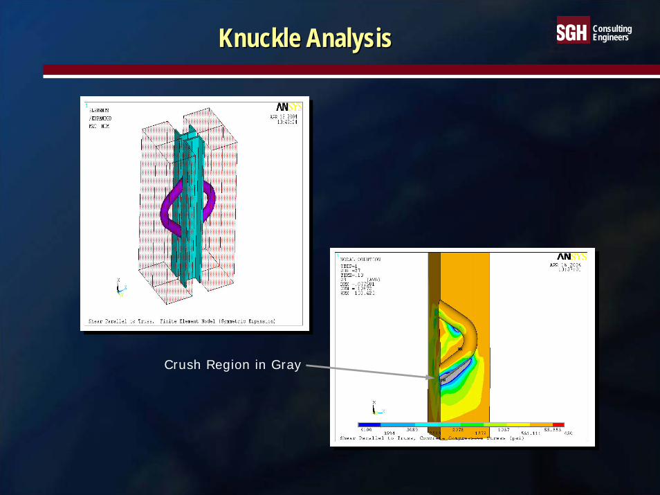
Sagging Observed in the Detailed Truss ModelSagging Observed in the Detailed Truss Model
MN
MX
-42.11-37.357
-32.603-27.849
-23.095-18.342
-13.588-8.834
-4.081.673211
Vertical displacement contour at 700 ˚CBuckling of web members
-100
-80
-60
-40
-20
0
20
40
0 100 200 300 400 500 600 700 800
Temperature of truss (°C)
Tota
l Hor
izon
tal R
eact
ion
Forc
e (k
ip)
web
mem
ber b
uckl
ing
inte
rior s
eat b
olt s
hear
-off
guss
et p
late
frac
ture
exte
rior s
eat b
olt s
hear
-
exte
rior s
eat w
alk-
off
•• After web members buckled, the After web members buckled, the truss pulled exterior columns in.truss pulled exterior columns in.
•• The tension force ranged from 9 The tension force ranged from 9 kip to 14 kip per column in this kip to 14 kip per column in this model.model.

ConsultingEngineersResponse of Reduced DOF Truss Model to TemperaturesResponse of Reduced DOF Truss Model to Temperatures
XYZ
M
XY
Z
-40
-35
-30
-25
-20
-15
-10
-5
0
0 100 200 300 400 500 600 700Temperature (˚C)
Vert
ical
Dis
plac
emen
t (in
)
Detailed Truss Model
Simplified Truss Model
-100
-80
-60
-40
-20
0
20
40
0 100 200 300 400 500 600 700Temperature (˚C)
Hor
izon
tal R
eact
ion
Forc
e pe
r Col
umn
(kip
)
Detailed Truss Model
Simplified Truss Model
Vertical displacement at midspan Horizontal reaction per exterior column

ConsultingEngineersCreep Effect on Vertical Displacement of Truss ModelCreep Effect on Vertical Displacement of Truss Model
1
MN
MX
X Y
Z
Simplified Truss Model at COL333 from Full Floor Model w/o Creep
-25.523-22.523
-19.522-16.521
-13.521-10.52
-7.52-4.519
-1.5191.482
MAR 29 200516:29:34
NODAL SOLUTION
STEP=5SUB =12TIME=2400UZ (AVG)RSYS=0DMX =25.523SMN =-25.523SMX =1.482
1
MN
MX
X Y
Z
Simplified Truss Model at COL333 from Full Floor Model with Creep
-44.184-39.117
-34.051-28.984
-23.918-18.851
-13.785-8.718
-3.6521.415
MAR 29 200515:45:08
NODAL SOLUTION
STEP=5SUB =54TIME=2400UZ (AVG)RSYS=0DMX =44.221SMN =-44.184SMX =1.415
w/o Creep at 2,400 sMax. = 25.5 in.
w/ Creep at 2,400 sMax. = 44.2 in.
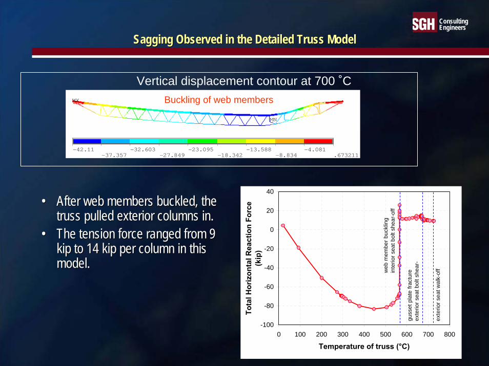
ConsultingEngineersFull Floor ModelFull Floor Model
1
APR 19 200420:40:22
ELEMENTS
TYPE NUM
Bridging Truss
Knuckle
Knuckle
Primary truss to bridging truss bottom chord connection
Primary truss to bridging truss top chord connection
Diagonal buckling and weld fracture
Primary Truss1
APR 19 200420:40:22
ELEMENTS
TYPE NUM
Bridging Truss
Knuckle
Knuckle
Primary truss to bridging truss bottom chord connection
Primary truss to bridging truss top chord connection
Diagonal buckling and weld fracture
Primary Truss
Component Models:• Knuckle• Truss Seat/Connections• Truss/Exterior Column
Subsystem Model: Full Floor• Concrete slab• Primary floor trusses• Bridging trusses• Transfer trusses• Strap anchors• Interior and exterior columns• Spandrels• Core beams

ConsultingEngineersFinite Element Model of Full FloorFinite Element Model of Full Floor
X Y
Z
SEP 2 200417:39:01
TYPE NUM
X Y
Z
X Y
Z
exterior column
spandrel
bridging truss
long-span primary truss
concrete slab
core beam
core column
short-span primary truss

ConsultingEngineersWTC 1 Floor 98 WTC 1 Floor 98 -- Temperatures at 50 minTemperatures at 50 min
1
X Y
Z
0
100200
300400
500600
700800
900950
SEP 18 200417:27:20
ELEMENTS
TEMPERATURESTMIN=24.41TMAX=920.169
1
X Y
Z
0
100200
300400
500600
700800
900950
SEP 18 200417:26:41
ELEMENTS
TEMPERATURESTMIN=20TMAX=924.418
N N
˚C˚C
Steel TemperaturesConcrete Slab Temperatures
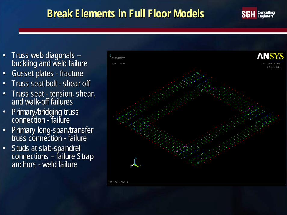
ConsultingEngineersBreak Elements in Full Floor ModelsBreak Elements in Full Floor Models
1
X Y
Z
WTC2 FL83
OCT 28 200415:12:57
ELEMENTS
SEC NUM
•• Truss web diagonals Truss web diagonals ––buckling and weld failure buckling and weld failure
•• Gusset plates Gusset plates -- fracturefracture•• Truss seat bolt Truss seat bolt -- shear offshear off•• Truss seat Truss seat -- tension, shear, tension, shear,
and walkand walk--off failuresoff failures•• Primary/bridging truss Primary/bridging truss
connection connection -- failurefailure•• Primary longPrimary long--span/transfer span/transfer
truss connection truss connection -- failurefailure•• Studs at slabStuds at slab--spandrel spandrel
connections connections –– failure Strap failure Strap anchors anchors -- weld failureweld failure

ConsultingEngineersWTC 1 Floor 98 WTC 1 Floor 98 -- Vertical Displacement at 100 minVertical Displacement at 100 min
1
MN
MX
X Y
Z
WTC1 FL98 - Maximum Damage Case Temperature at 6000 sec
-49.045-43.13
-37.215-31.301
-25.386-19.472
-13.557-7.643
-1.7284.187
OCT 29 200409:46:43
NODAL SOLUTION
STEP=15SUB =18TIME=6000UZ (AVG)RSYS=0DMX =49.136SMN =-49.045SMX =4.187
1
MN
MX
X Y
Z
WTC1 FL98 - Maximum Damage Case Temperature at 6000 sec
-49.045-43.113
-37.181-31.249
-25.318-19.386
-13.454-7.522
-1.594.341
OCT 29 200409:46:42
NODAL SOLUTION
STEP=15SUB =18TIME=6000UZ (AVG)RSYS=0DMX =49.136SMN =-49.045SMX =4.341
N
Floor/wall disconnection
N
Max displacement = 49.0 in.
5x displacement magnification

ConsultingEngineersWTC 1 Floor 96 WTC 1 Floor 96 –– Effect of FireproofingEffect of Fireproofing
1
X Y
Z
0
100200
300400
500600
700800
900950
SEP 15 200420:21:51
ELEMENTS
TEMPERATURESTMIN=29.539TMAX=902.356
1
MN
MX
X Y
Z
WTC1 FL96 - Maximum Damage Case Temperature at 6000 sec
-22.431-19.594
-16.756-13.918
-11.08-8.243
-5.405-2.567
.270363.108
SEP 27 200409:20:52
NODAL SOLUTION
STEP=11SUB =8TIME=6000UZ (AVG)RSYS=0DMX =22.529SMN =-22.431SMX =3.108
N N
Area of fireproofing damage
•• Maximum temperature of steel members with fireproofing reached aMaximum temperature of steel members with fireproofing reached approximately 400pproximately 400 ˚C.˚C.•• Maximum temperature of steel members without fireproofing exceedMaximum temperature of steel members without fireproofing exceeded 600ed 600 ˚C and often ˚C and often
reached 800reached 800 ˚C.˚C.
Temperature of steel membersat 100 min
Vertical displacement(5x displacement magnification)

ConsultingEngineers
Exterior WallsExterior Walls

ConsultingEngineersOneOne--Story Exterior Column ModelStory Exterior Column Model
2 in. pushdown at room temperature
2 in. pushdown at 700 °C

ConsultingEngineersAxial Load Deflection of Exterior ColumnAxial Load Deflection of Exterior Column
0
175
350
525
700
875
1050
1225
0.0 0.5 1.0 1.5 2.0 2.5 3.0Vertical Displacement (in)
Axi
al L
oad
(kip
s)
1-Story (RT)
1-Story (700C)
2-Story (RT)
2-Story (400C)
3-Story (RT)
3-Story (400C)
Elastic local buckling load for 1-story high column at RT =1004 Kip
Axial yield load of column at RT =1177 Kip
Gravity load demand
Elastic local buckling load at 700C = 682 Kip
Axial yield load of column at 700C = 444 Kip

ConsultingEngineers
10 ft
52 in.
40 in. 40 in.
12 ft
Prefabricated panel
Column splice
Spandrel splice
Floor 99
Floor 98
Floor 97
Floor 96
Floor 95
Floor 94
Floor 93
Floor 92
Floor 91
A A
CO
L158
C
OL1
57
CO
L156
C
OL1
55
CO
L154
C
OL1
53
CO
L152
C
OL1
51
CO
L150
Exterior Wall ModelExterior Wall Model
Subsystem Model: 9x9 wall section• Columns• Spandrels• Column splices• Spandrel splices

ConsultingEngineersExterior Wall Load CasesExterior Wall Load Cases
XYZ
Lateral FloorLoads
VerticalLoads
•• All floors connected All floors connected •• Two floors disconnectedTwo floors disconnected•• Three floors disconnectedThree floors disconnected•• Three floors disconnected Three floors disconnected
with pullwith pull--in forcesin forces•• Three floors disconnected Three floors disconnected
with push down forces. with push down forces.

ConsultingEngineers
Large Inelastic Buckling of Spandrel Large Inelastic Buckling of Spandrel and Partial Separation at Connectionsand Partial Separation at Connections
Add 14 Tear 94
50x displacement magnification

ConsultingEngineers
Instability of Exterior Wall subjected Instability of Exterior Wall subjected to Horizontal Pullto Horizontal Pull--in Forces at Three Floorsin Forces at Three Floors
19uy2.avi10X displacement magnification

Simpson Gumpertz & HegerSimpson Gumpertz & Heger Consulting EngineersConsulting Engineers
Building Engineering Building Engineering Infrastructure and Special Structures Infrastructure and Special Structures Construction EngineeringConstruction Engineering
Global Analysis of WTC 1 and WTC 2Global Analysis of WTC 1 and WTC 2

ConsultingEngineersGlobal ModelsGlobal Models
•• ANSYS models were developed for nonlinear ANSYS models were developed for nonlinear large deflection analysis of the towers.large deflection analysis of the towers.
•• WTC 1: Truncated below Floor 91 with WTC 1: Truncated below Floor 91 with vertical springs for stiffness of floors below.vertical springs for stiffness of floors below.
•• WTC 2: Truncated below Floor 77 with vertical WTC 2: Truncated below Floor 77 with vertical springs for stiffness of floors below and springs for stiffness of floors below and superelement above Floor 86.superelement above Floor 86.
1
MN
MX
X Y
Z
WTC1 - Severe Temp at 6000s w/5kip pull
-6.499-5.757
-5.015-4.273
-3.532-2.79
-2.048-1.306
-.564029.177856
MAR 30 200510:23:21
NODAL SOLUTION
STEP=33SUB =1437TIME=150UZ (AVG)RSYS=0DMX =42.979SMN =-6.499SMX =.177856
WTC 1
•• Tower Model FeaturesTower Model FeaturesColumns included creep and inelastic buckling. Spandrels were axially released to prevent local plate buckling, without loss of bending and shear stiffness.Office floors modeled as a membrane capable of transferring in-plane loads between core and exterior wall.Core slab and beams with moment connection were modeled simulating both membrane and bending stiffness for load transfer between columns. Core beams without moment connections were not modeled. Core slab above these beams was modeled to match the in-plane stiffness of the composite floor.
N

ConsultingEngineersGlobal ModelsGlobal Models
•• Core and exterior columns had temperatureCore and exterior columns had temperature--dependent propertiesdependent properties
Thermal expansionPlasticity Creep
•• Gravity Loads Gravity Loads Self-weight plus 8 psf superimposed deadLive (25% of design live load)Weight of antenna (750 kip) at the top of WTC 1
•• Thermal Loads Thermal Loads Temperatures at 10 min intervals
1
MNMX
XYZ
WTC2 Reduced Model At 2540s
-11.25-10
-8.75-7.5
-6.25-5
-3.75-2.5
-1.250
MAR 2 200510:45:47
NODAL SOLUTION
STEP=17SUB =523TIME=63.523UZ (AVG)RSYS=0DMX =61.911SMN =-11.096
WTC 2
•• FloorsFloorsFull floor models were not included in global models due to computational limitationsEffects of the floor disconnections and inward pull forces due to floor sagging were included
N
ConsultingEngineers
WTC 1 South Wall
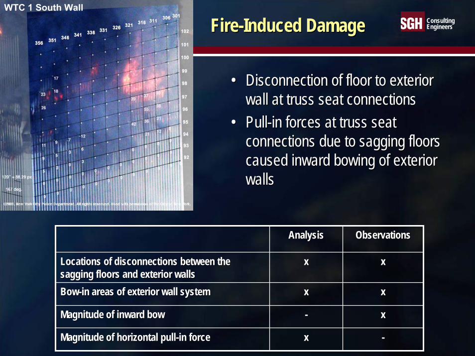
FireFire--Induced DamageInduced Damage
•• Disconnection of floor to exterior Disconnection of floor to exterior wall at truss seat connections wall at truss seat connections
•• PullPull--in forces at truss seat in forces at truss seat connections due to sagging floors connections due to sagging floors caused inward bowing of exterior caused inward bowing of exterior wallswalls
AnalysisAnalysis ObservationsObservations
Locations of disconnections between the Locations of disconnections between the sagging floors and exterior wallssagging floors and exterior walls
xx xx
BowBow--in areas of exterior wall systemin areas of exterior wall system xx xx
Magnitude of inward bowMagnitude of inward bow -- xx
Magnitude of horizontal pullMagnitude of horizontal pull--in forcein force xx --
ConsultingEngineers
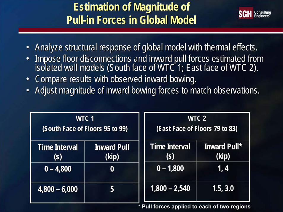
Estimation of Magnitude of Estimation of Magnitude of PullPull--in Forces in Global Modelin Forces in Global Model
•• Analyze structural response of global model with thermal effectsAnalyze structural response of global model with thermal effects..•• Impose floor disconnections and inward pull forces estimated froImpose floor disconnections and inward pull forces estimated from m
isolated wall models (South face of WTC 1; East face of WTC 2).isolated wall models (South face of WTC 1; East face of WTC 2).•• Compare results with observed inward bowing.Compare results with observed inward bowing.•• Adjust magnitude of inward bowing forces to match observations.Adjust magnitude of inward bowing forces to match observations.
WTC 2WTC 2(East Face of Floors 79 to 83)(East Face of Floors 79 to 83)
Time Interval Time Interval (s)(s)
Inward Pull* Inward Pull* (kip)(kip)
0 0 –– 1,800 1,800 1, 41, 4
1,800 1,800 –– 2,5402,540 1.5, 3.01.5, 3.0
WTC 1 WTC 1 (South Face of Floors 95 to 99)(South Face of Floors 95 to 99)
Time Interval Time Interval (s)(s)
Inward Pull Inward Pull (kip)(kip)
0 0 –– 4,800 4,800 00
4,800 4,800 –– 6,0006,000 55
* Pull forces applied to each of two regions

ConsultingEngineersImportant Factors in Global AnalysisImportant Factors in Global Analysis
•• Aircraft damage Aircraft damage →→ Load redistributionLoad redistribution•• Thermal expansion Thermal expansion →→ Load redistributionLoad redistribution•• Creep of steel in high temperature Creep of steel in high temperature →→
Displacement increase, column axial shortening, Displacement increase, column axial shortening, and load redistribution and load redistribution
•• Thermal weakening/softening of steel and concrete Thermal weakening/softening of steel and concrete in high temperaturein high temperature
Loss of strength → Component failure and load redistributionLoss of stiffness → Buckling and load redistribution

ConsultingEngineers
Results from Global Analysis of WTC 2Results from Global Analysis of WTC 2

ConsultingEngineers
Vertical Displacement of Exterior Wall Vertical Displacement of Exterior Wall of WTC 2 (Floor 77 to Floor 86)of WTC 2 (Floor 77 to Floor 86)
Before Aircraft Impact At 43 min1
MN
MX
XYZ
WTC2 Reduced Model At BfrImp
-11.25-10
-8.75-7.5
-6.25-5
-3.75-2.5
-1.250
MAR 2 200510:51:30
NODAL SOLUTION
STEP=1SUB =1TIME=.100E-02UZ (AVG)RSYS=0DMX =3.032SMN =-2.971SMX =-2.142
1
MNMX
XYZ
WTC2 Reduced Model At 2540s
-11.25-10
-8.75-7.5
-6.25-5
-3.75-2.5
-1.250
MAR 2 200510:45:47
NODAL SOLUTION
STEP=17SUB =523TIME=63.523UZ (AVG)RSYS=0DMX =61.911SMN =-11.096
Min = -11 in Max = 0.0 inMin = -3.0 in Max = -2.1 in
N N
(Downward displacement is negative)

ConsultingEngineers
Vertical Displacement of CoreVertical Displacement of Coreof WTC 2 (Floor 77 to Floor 86)of WTC 2 (Floor 77 to Floor 86)
Before Aircraft Impact 43 min1
MN
MX
XYZ
WTC2 Reduced Model At 2540s
-13.05-11.6
-10.15-8.7
-7.25-5.8
-4.35-2.9
-1.450
MAR 2 200510:45:53
NODAL SOLUTION
STEP=17SUB =523TIME=63.523UZ (AVG)RSYS=0DMX =13.576SMN =-12.982
1
MN
MX
XYZ
WTC2 Reduced Model At AftrImp
-13.05-11.6
-10.15-8.7
-7.25-5.8
-4.35-2.9
-1.450
MAR 2 200510:36:08
NODAL SOLUTION
STEP=1SUB =68TIME=.001UZ (AVG)RSYS=0DMX =10.229SMN =-10.052
N N
Min = -10 in Max = 0.0 in Min = -13 in Max = 0.0 in
(Downward displacement is negative)

ConsultingEngineers
OutOut--ofof--Plane Displacement of Plane Displacement of East Wall of WTC 2East Wall of WTC 2
View from southeast at 43 min.
N
201359 301
77
81
85
Min = -4.0 in Max = 61.7 in
FL 85
FL 77
FL 81
301
359
N
FL 85
FL 77
FL 81
301
359
N
201359 301
77
81
85
0
15
30
45
60
0 10 20 30 40 50
Time, min
Max
imum
out
-of-p
lane
dis
plac
emen
tin
eas
t wal
l, in
Critical displacement

ConsultingEngineers
Variation of Vertical Displacements Variation of Vertical Displacements at Floor 86 of WTC 2at Floor 86 of WTC 2
At 43 minBefore Impact
N~3.0 in
~4.0 in
~3.0 in
~3.0 in
N~3.0 in
~4.0 in
~3.0 in
~3.0 in
~11 in
~10 in
~4.5 in
~2.5 in ~1.2 in
~5.0 in~8.5 in
13 in 12 in 11 in
N
Likely zone the tower tilts around
~11 in
~10 in
~4.5 in
~2.5 in ~1.2 in
~5.0 in~8.5 in
13 in 12 in 11 in
N
Likely zone the tower tilts around
(Downward displacement is positive)

ConsultingEngineers
Tilt Above Floor 86 of WTC 2 Tilt Above Floor 86 of WTC 2 at 43 min (Total Displacements)at 43 min (Total Displacements)
20X Magnification
1
MN
MX
XY
Z
WTC-2 Severe Case Temperature Analysis
3.2985.332
7.3669.399
11.43313.467
15.517.534
19.56821.601
MAR 14 200512:38:28
NODAL SOLUTION
STEP=7SUB =1TIME=.007USUM (AVG)RSYS=0DMX =21.601SMN =3.298SMX =21.601
Undeformed building edge
N

ConsultingEngineers
Elastic + Plastic Strain in Columns Elastic + Plastic Strain in Columns ––Maximum between Floor 78 and Floor 84 of WTC 2Maximum between Floor 78 and Floor 84 of WTC 2
After Impact
1001
508501
1008N
~0.04
~0.05
~0.04
~0.05~0.05
1001
508501
1008N
~0.04
~0.05
~0.04
~0.05~0.05
Before Impact
1001
508501
1008N
~0.04
9
~0.04
~0.04~0.15
.60
~0.34
~0.10
~0.0
~0
1001
508501
1008N
~0.04
9
~0.04
~0.04~0.15
.60
~0.34
~0.10
~0.0
~0
Compression is taken as positive.Strain values are in %.

ConsultingEngineers
Elastic + Plastic Strain in ColumnsElastic + Plastic Strain in ColumnsMaximum between Floor 78 and Floor 84 of WTC 2Maximum between Floor 78 and Floor 84 of WTC 2
At 40 min
0.9
1001
508501
1008N
0.9
1001
508501
1008N
At 43 min
0.9
1001
508501
1008N
~1.3
~0.09
~0.03
~0.35
~0.75
~0.80
~0.40
~0.30
~0.03
~2.20
~1.0
0.9
1001
508501
1008N
~1.3
~0.09
~0.03
~0.35
~0.75
~0.80
~0.40
~0.30
~0.03
~2.20
~1.0
Compression is taken as positive.Strain values are in %.

ConsultingEngineers
Elastic + Plastic + Creep Strain in ColumnsElastic + Plastic + Creep Strain in ColumnsMaximum between Floor 78 and Floor 84 of WTC 2Maximum between Floor 78 and Floor 84 of WTC 2
6.9
1001
508501
1008N
~2.6
~0.09
~0.03
~4.0~3.20
~0.80
~0.40
~0.30
~0.03
~1.1~2.3
~5.6
6.9
1001
508501
1008N
~2.6
~0.09
~0.03
~4.0~3.20
~0.80
~0.40
~0.30
~0.03
~1.1~2.3
~5.6
At 43 min
1001
508501
1008N
0.50
0.09
0.04
0.90
1.3
0.60
0.35
0.11
0.04
0.70
1001
508501
1008N
0.50
0.09
0.04
0.90
1.3
0.60
0.35
0.11
0.04
0.70
At 20 min
Compression is taken as positive.Strain values are in %.

ConsultingEngineersWTC 2 Hat TrussWTC 2 Hat Truss
•• Hat truss was part of the Hat truss was part of the superelementsuperelement
•• Hat truss members and Hat truss members and connections were checked for connections were checked for failurefailure
•• Analysis found that: Analysis found that: Failure of several column splices in the southeast corner of the core occurred due to impactAdditional column splices failed and an outrigger buckled due to subsequent firesSuch failures did not propagate and reduce the load on the overstressed outrigger.
1
XY
Z
WTC-2 Severe Case Temperature Analysis
MAR 14 200519:22:03
ELEMENTS
TYPE NUM
N
N
O
B
A
P
CE
D
J
I
G
F
K
H
ML
111 - 110
131 - 130 - 129218 - 217
229 - 228232 - 231
243 - 242
349 - 350
329 - 330 - 331
310 - 311
442 - 443
431 - 432428 - 429
417 - 418
150 - 149

ConsultingEngineersWTC 2 Global Analysis ResultsWTC 2 Global Analysis Results
After Aircraft ImpactAfter Aircraft Impact•• WTC 2 was stable after impact and had considerable reserve capacWTC 2 was stable after impact and had considerable reserve capacity.ity.•• Severed columns in the southeast corner of the core caused the cSevered columns in the southeast corner of the core caused the core to lean to the southeast. The ore to lean to the southeast. The
tendency of the core to lean was resisted by floors and exteriortendency of the core to lean was resisted by floors and exterior walls.walls.•• After impact, core loads decreased by 6%, east wall loads increaAfter impact, core loads decreased by 6%, east wall loads increased by 24%, and the north wall loads sed by 24%, and the north wall loads
decreased by 10%.decreased by 10%.
Effects of Fires and Damaged FireproofingEffects of Fires and Damaged Fireproofing•• Thermal expansion of the core columns caused core loads to increThermal expansion of the core columns caused core loads to increase until plastic and creep strains ase until plastic and creep strains
exceeded thermal strains and the columns shortened and unloaded.exceeded thermal strains and the columns shortened and unloaded.•• Loads were transferred between the exterior wall and the core prLoads were transferred between the exterior wall and the core primarily through the hat truss.imarily through the hat truss.•• The floors sagged and pulled inward on the east wall shortly aftThe floors sagged and pulled inward on the east wall shortly after impact. The sag continued to increase er impact. The sag continued to increase
due to the persistence of the fires on the east side of the towedue to the persistence of the fires on the east side of the tower. r. •• The east wall bowed inward 10 in. approximately 20 min after impThe east wall bowed inward 10 in. approximately 20 min after impact. The bowing increased until act. The bowing increased until
collapse.collapse.•• Loads were transferred between exterior walls through the spandrLoads were transferred between exterior walls through the spandrels.els.
Collapse InitiationCollapse Initiation•• When the east wall buckled, the loads were transferred to the weWhen the east wall buckled, the loads were transferred to the weakened core and adjacent exterior walls.akened core and adjacent exterior walls.•• The building section above the impact area tilted to the southeaThe building section above the impact area tilted to the southeast.st.

ConsultingEngineers
Results from Global Analysis of WTC 1Results from Global Analysis of WTC 1

ConsultingEngineers
Vertical Displacement of Vertical Displacement of Exterior Walls of WTC 1Exterior Walls of WTC 1
1
MN
MX
X Y
Z
WTC1 - Severe Temp at 6000s w/5kip pull
-6.499-5.757
-5.015-4.273
-3.532-2.79
-2.048-1.306
-.564029.177856
MAR 30 200510:23:21
NODAL SOLUTION
STEP=33SUB =1437TIME=150UZ (AVG)RSYS=0DMX =42.979SMN =-6.499SMX =.177856
FL93FL95FL97FL99
At 100 min
N
Before Impact
1
MN
MX
X Y
Z
WTC1 - Gravity before Impact w/o Const
-3.285-2.92
-2.555-2.19
-1.825-1.46
-1.095-.730004
-.3650020
MAR 16 200509:59:08
NODAL SOLUTION
STEP=1SUB =2TIME=.100E-02UZ (AVG)RSYS=0DMX =3.286SMN =-3.285
Max. = 3.3 in. N
FL93FL95FL97FL99
Max. = 6.5 in.
1
MN
MX
XYZ
WTC1 - Severe Temp at 6000s w/5kip pull
-6.499-5.757
-5.015-4.273
-3.532-2.79
-2.048-1.306
-.564029.177856
MAR 30 200510:23:21
NODAL SOLUTION
STEP=33SUB =1437TIME=150UZ (AVG)RSYS=0DMX =42.979SMN =-6.499SMX =.177856
N FL93FL95FL97FL99
(Downward displacement is negative)

ConsultingEngineers
Vertical Displacement of Vertical Displacement of Core of WTC 1Core of WTC 1 At 100 min
1
MNMX
X Y
Z
WTC1 - Severe Temp at 6000s w/5kip pull
-8.571-7.616
-6.661-5.706
-4.752-3.797
-2.842-1.887
-.931941.022969
MAR 30 200510:24:23
NODAL SOLUTION
STEP=33SUB =1437TIME=150UZ (AVG)RSYS=0DMX =27.32SMN =-8.571SMX =.022969
NFL93FL95FL97FL99Before Impact
1
MN
MX
X Y
Z
WTC1 - Gravity before Impact w/o Const
-4.246-3.775
-3.303-2.831
-2.359-1.887
-1.415-.943626
-.4718130
FEB 14 200509:51:34
NODAL SOLUTION
STEP=1SUB =2TIME=.100E-02UZ (AVG)RSYS=0DMX =4.247SMN =-4.246
NFL93FL95FL97FL99
Max. = 4.2 in.
Max. = 8.6 in.
1
MN
MX
XYZ
WTC1 - Severe Temp at 6000s w/5kip pull
-8.571-7.616
-6.661-5.706
-4.752-3.797
-2.842-1.887
-.931941.022969
MAR 30 200510:24:23
NODAL SOLUTION
STEP=33SUB =1437TIME=150UZ (AVG)RSYS=0DMX =27.32SMN =-8.571SMX =.022969
NFL93FL95FL97FL99
(Downward displacement is negative)

ConsultingEngineersWTC 1 South Wall OutWTC 1 South Wall Out--ofof--Plane DisplacementPlane Displacement
At 100 min1
MN
MX
XY
Z
WTC1 Severe Temp at 6000s w/5kip pull - South Face (5X)
-.7010594.135
8.97213.808
18.64423.481
28.31733.153
37.9942.826
MAR 30 200510:23:38
NODAL SOLUTION
STEP=33SUB =1437TIME=150UY (AVG)RSYS=0DMX =42.979SMN =-.701059SMX =42.826
COL301
COL359
FL93
FL95
FL97
FL99
FL93
FL95
FL97
FL99
Max. = 42.8 in.
0
5
10
15
20
25
30
35
40
45
80 85 90 95 100
Time (min)
Max
imum
Inw
ard
Bow
ing
(in)
Looking from the outside of the buildingInward displacement is shown as positive displacement

ConsultingEngineers
Elastic + Plastic Strain in Columns Elastic + Plastic Strain in Columns Maximum between Floor 93 and Floor 99
Severed or Heavily DamagedElastic + Plastic Strain
0.57
Col501 Col508
Col1001 Col1008Severed or Heavily DamagedElastic + Plastic Strain
0.57
Col501 Col508
Col1001 Col1008
Severed or Heavily DamagedElastic + Plastic Strain
0.98
Col501 Col508
Col1001 Col1008
Severed or Heavily DamagedElastic + Plastic Strain
0.98
Col501 Col508
Col1001 Col1008
After Impact
At 100 min
Maximum between Floor 93 and Floor 99
NMaximum strain is given in %.Compression is taken as positive.
Elastic + Plastic Strain
0.07
Col501 Col508
Col1001 Col1008
Elastic + Plastic Strain
0.07
Col501 Col508
Col1001 Col1008
Before Impact

ConsultingEngineers
Severed or Heavily DamagedElastic + Plastic + Creep Strain
7.3
Col501 Col508
Col1001 Col1008
Severed or Heavily DamagedElastic + Plastic + Creep Strain
7.3
Col501 Col508
Col1001 Col1008
Severed or Heavily DamagedElastic + Plastic + Creep Strain
6.7
Col501 Col508
Col1001 Col1008
Severed or Heavily DamagedElastic + Plastic + Creep Strain
6.7
Col501 Col508
Col1001 Col1008
Elastic + Plastic + Creep Strain in ColumnsElastic + Plastic + Creep Strain in ColumnsMaximum between Floor 93 and Floor 99Maximum between Floor 93 and Floor 99
N
Maximum strain is given in %.Compression is taken as positive.
At 50 min
At 100 min
Severed or Heavily DamagedElastic + Plastic + Creep Strain
1.39
Col501 Col508
Col1001 Col1008
Severed or Heavily DamagedElastic + Plastic + Creep Strain
1.39
Col501 Col508
Col1001 Col1008
At 10 min

ConsultingEngineersWTC 1 Hat TrussWTC 1 Hat Truss
•• Analysis found no failure of hat truss members or supporting corAnalysis found no failure of hat truss members or supporting core columns.e columns.1
MN
MX
X Y
Z
WTC1 Severe Temp at 6000s w/5kip pull - Hat Truss
-.351E+07-.292E+07
-.233E+07-.174E+07
-.114E+07-553893
36667627226
.122E+07.181E+07
MAR 30 200510:23:32
ELEMENT SOLUTION
STEP=33SUB =1437TIME=150SMIS1TOPDMX =6.782SMN =-.351E+07SMX =.181E+07
N
Axial force in hat truss at 100 min

ConsultingEngineersWTC 1 Global Analysis ResultsWTC 1 Global Analysis Results
After Aircraft ImpactAfter Aircraft Impact•• WTC 1 was stable after impact and had considerable reserve capacWTC 1 was stable after impact and had considerable reserve capacity.ity.•• Severed core columns in the north side of the core caused it to Severed core columns in the north side of the core caused it to lean slightly to the north.lean slightly to the north.•• After impact, core loads increased by 1%, east and wall loads inAfter impact, core loads increased by 1%, east and wall loads increased by 7%, and the north and creased by 7%, and the north and
south walls decreased by 7%.south walls decreased by 7%.
Effects of Fires and Damaged FireproofingEffects of Fires and Damaged Fireproofing•• Thermal expansion of the core columns caused core loads to increThermal expansion of the core columns caused core loads to increase until plastic and creep strains ase until plastic and creep strains
exceeded thermal strains and the columns shortened and unloaded.exceeded thermal strains and the columns shortened and unloaded.•• Loads were transferred between the exterior wall and the core prLoads were transferred between the exterior wall and the core primarily through the hat truss.imarily through the hat truss.•• Fires progressing from the north to the south side of the tower Fires progressing from the north to the south side of the tower caused the floors to sag and pull inward caused the floors to sag and pull inward
on the south wall approximately 80 min after impact. on the south wall approximately 80 min after impact. •• The south wall bowed inward, reaching approximately 55 in. of inThe south wall bowed inward, reaching approximately 55 in. of inward displacement just before ward displacement just before
collapse.collapse.•• Loads were transferred between exterior walls through the spandrLoads were transferred between exterior walls through the spandrels.els.
Collapse InitiationCollapse Initiation•• When the south wall buckled, the loads were transferred to the wWhen the south wall buckled, the loads were transferred to the weakened core and adjacent exterior eakened core and adjacent exterior
walls.walls.•• The building section above the impact area tilted to the south.The building section above the impact area tilted to the south.