Embed Size (px)
Citation preview
Structural behavior analysis of a continuous steel truss arch railway bridge integrating monitoring data
Yong-sheng Song1, You-liang Ding2, Han-wei Zhao3, Gao-xin Wang4, Ai-qun Li5 and Bao-ya Cao6
1) Jinling Institute of Technology, 99 Hongjing Avenue, Jiangning District, Nanjing 211129,
China (corresponding author). 2) Key Laboratory of Concrete and Prestressed Concrete Structures of Ministry of
Education, Southeast Univ., 2 Sipailou Rd., Xuanwu District, Nanjing 210096, China. Abstract
Using theoretical modeling combined with monitoring data, the typical dynamic and static behaviors of a continuous steel truss arch railway bridge are evaluated. The dynamic behavior involves an impact factor induced by the action of running trains, and the static behavior refers to axial bending performance and the stress distribution among different planes of the truss. The transverse position, length and speed of running trains are introduced to conduct an analysis of their influences on the dynamic and static behaviors of the bridge superstructure. A structural safety evaluation is also conducted by comparison with the provisions recommended by design codes and by analysis of absolute stress. It is concluded that three types of members present different dynamic behaviors and that the value of the impact factor for chords B exceeds the provision recommended by the design codes. Chords C present the greatest ratio of bending stress versus axial stress. An imbalance of stress distribution exists among the three planes of the truss, and the difference is the smallest when trains run along the middle railways. Because the train-induced stress is considerably lower, the dynamic and static performances of the bridge are within the scope of safety. Keywords: railway bridges; steel truss arch; impactor factor; axial bending behavior; stress distribution
1 Ph. D, E-mail: [email protected].
2 Professor, E-mail: [email protected].
3 PhD Student, E-mail: [email protected].
4 PhD Student, E-mail: [email protected].
5 Professor, E-mail: [email protected].
6 PhD Student, E-mail: [email protected].
1. Introduction
The construction of high-speed railways is limited by a variety of environmental factors. Various bridges have to be constructed to overcome factors such as rivers and valleys. Unlike highway bridges, the requirements for high-speed railway bridges are considerably stricter with respect to the stiffness and stability of the superstructure. The parameter of span range is one of the typical factors that determine the design of bridge superstructures. Special spans can be divided into two categories based on the length of the main span: medium length (100–200 m) and large length (200–500 m).1 Tied steel arch, rigid frame and arch-rigid frame hybrid are three commonly used structural forms for medium-length spans.2,3 Compared with medium-length bridges, the main girder of a long-span bridge is known to be considerably more flexible. The structural forms of steel truss arch and cable-stayed are two means to overcome the problem.4
In this paper, the structural behaviors of a steel truss arch system are studied by integrating the typical dynamic and static properties of strain responses. Dynamic behavior has attracted more attention for bridges with large span lengths.5 Due to the higher serviceability limits compared to conventional railway bridge design, the technical issues associated with the dynamic response of high-speed railway bridges have been investigated in many previous studies, such as seismic performance,6-10 track structure, interaction,11,12 creep effect,13,14 thermal effect,15 and so forth. However, few investigations have focused on the effect of the impact factor by comparing with and further verifying the design codes. The impact factor is calculated to evaluate the dynamic magnitude effect of stress under moving loads in the design period. Therefore, the responses of stress calculated based on static load have to be multiplied by the impact factor. Various investigations have been conducted on the dynamic behavior of many forms of bridges. Related forms of bridges include simple railway bridges with a steel plate girder, multi-girder concrete bridges, continuous bridges with a skew box girder, composite concrete-steel cellular straight bridges, and curved continuous bridges with a composite multiple-box girder.16-20 However, the newly emerging bridge form of steel truss arch has not been investigated because of its complex structural composition. Therefore, different types of members may present distinct dynamic behavior performance. In addition to its property of complex structural composition, the act of trains running at high speed and the uncertainty in transverse positions are another two significant influencing factors.
Because of the complex structure composed of members distributed spatially, the static behavior of the steel truss arch system is more difficult to understand and master. Some investigations have been conducted to obtain the stress distribution under dead loads and the rules for how stiffness variation influences the stress redistribution.21,22 However, few studies have been conducted on the stress distribution under live loads. For railway bridges, running trains are one of the most significant live loads. Thus, the mechanism of stress distribution under running trains must be taken into consideration.
The Dashengguan Railway Bridge is selected as the case study. This bridge spans across the Yangtze River in China, and its superstructure is a steel truss arch system. To investigate the performance under actual service conditions, structural monitoring systems
have been installed at typical locations for on-line evaluation of various structural behaviors. By analyzing the characteristics of strain curves of different members under various running trains, this paper specifically focuses on the dynamic and static behaviors of the superstructure through monitoring combined with finite element modeling. Investigation is first conducted to obtain the impact-factor property of different members under various running trains. Another investigation involves the axial-bending behavior of typical members under running trains either. In addition, the stress distribution among three planes of the truss is finally investigated to verify integrality of the spatial structure. Influencing analysis is also involved during above investigations. Related parameters include the length, the transverse position as well as the speed of running trains. 2. Bridge Description and its SHMS 2.1 Description of Dashengguan Railway Bridge
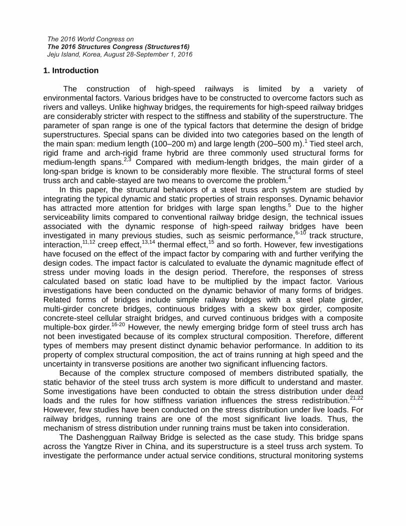
Fig. 1 presents the actual view of the Dashengguan Railway Bridge as well as the side and cross-sectional views with the geometrical dimensions in detail. The Dashengguan Railway Bridge provides a passageway with four railway lines for trains along the Beijing-Shanghai and Shanghai-Wuhan-Chengdu railways. In addition, the bridge will support an urban light rail with two lines for Nanjing City in the future. Fig. 1(c) shows the transverse distribution of the aforementioned six railway lines. In addition, there are two types of high-speed trains that run along these four rails with 8 and 16 carriages. The design speeds for trains along the Beijing-Shanghai and Shanghai-Wuhan-Chengdu railway lines are 300 km/h and 200 km/h, respectively. Additionally, the design speed for the urban light rail is 80 km/h.
A continuous steel truss arch was adopted as the superstructure of the bridge. There are six spans that compose the main bridge in the longitudinal direction. The distribution of spans is symmetrical, and the lengths of the half-side spans are sequentially 180 m, 192 m and 336 m from the side to the middle. In addition, the bridge superstructure consists of three planes of steel truss arches by connection of transverse trusses. A two-tube combined truss is applied as the arch ring of the steel truss arch. The maximum height of the combined truss is 16.0 m at the mid-span section. The ratio of maximum height versus span length is 0.25. Vertical steel hangers are applied to connect the steel truss arch with the chord members supporting the bridge deck. An orthotropic steel deck is adopted as the bridge deck, and it is directly welded to the chord members. Three grades of steel material are applied to produce the steel members. The members of the main trusses are applied with the steel material of 370 MPa.
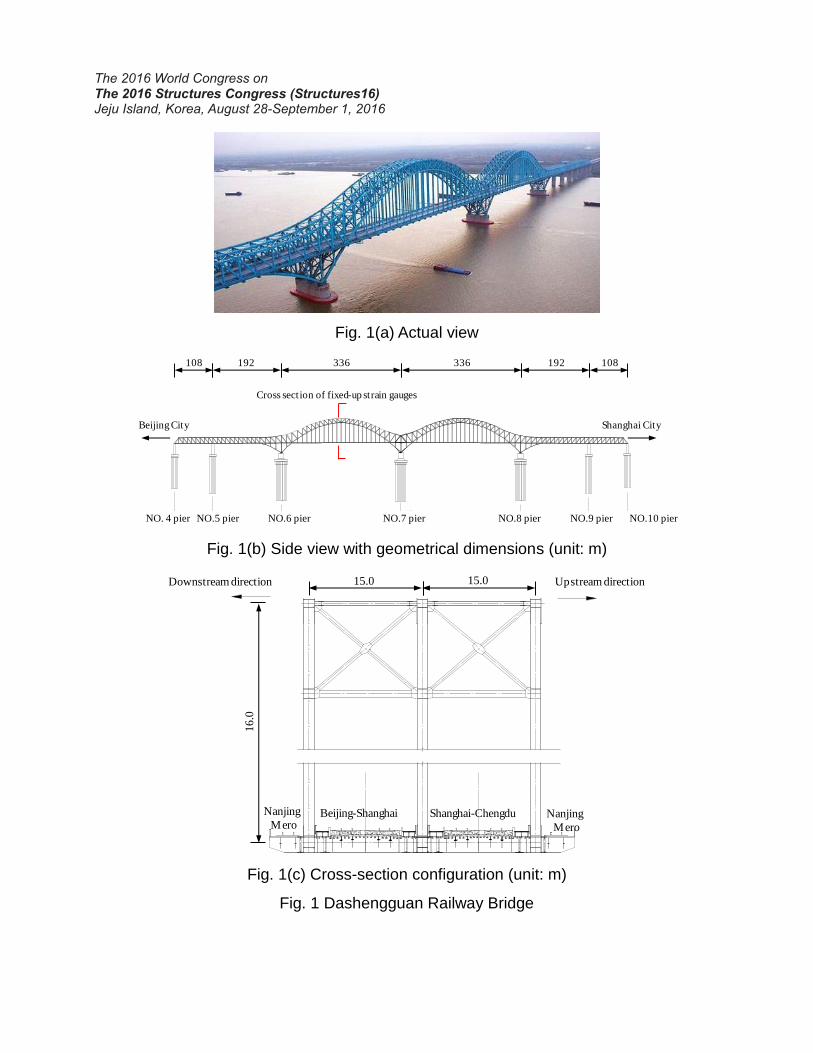
Fig. 1(a) Actual view
1
1
NO. 4 pier NO.5 pier NO.6 pier NO.7 pier NO.8 pier NO.9 pier NO.10 pier
Beijing City Shanghai City
Cross section of fixed-up strain gauges
108 192 336 336 192 108
Fig. 1(b) Side view with geometrical dimensions (unit: m)
Downstream direction Upstream direction
16
.0
15.0 15.0
Beijing-Shanghai Shanghai-ChengduNanjing
MeroNanjing
Mero
Fig. 1(c) Cross-section configuration (unit: m)
Fig. 1 Dashengguan Railway Bridge
2.2 Overview of structural monitoring system
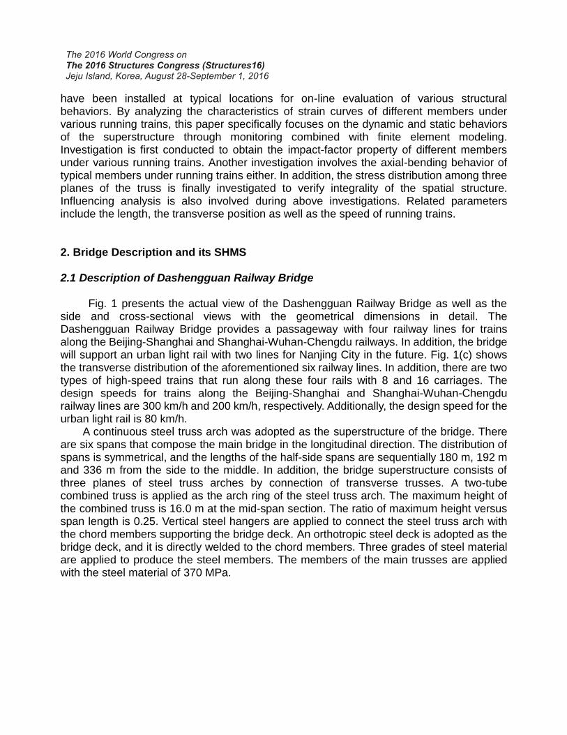
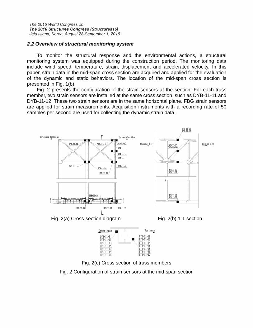
To monitor the structural response and the environmental actions, a structural monitoring system was equipped during the construction period. The monitoring data include wind speed, temperature, strain, displacement and accelerated velocity. In this paper, strain data in the mid-span cross section are acquired and applied for the evaluation of the dynamic and static behaviors. The location of the mid-span cross section is presented in Fig. 1(b).
Fig. 2 presents the configuration of the strain sensors at the section. For each truss member, two strain sensors are installed at the same cross section, such as DYB-11-11 and DYB-11-12. These two strain sensors are in the same horizontal plane. FBG strain sensors are applied for strain measurements. Acquisition instruments with a recording rate of 50 samples per second are used for collecting the dynamic strain data.
Fig. 2(a) Cross-section diagram Fig. 2(b) 1-1 section
Fig. 2(c) Cross section of truss members
Fig. 2 Configuration of strain sensors at the mid-span section
3. Finite element modeling combining strain measurement data 3.1 Measured strain curves of typical members
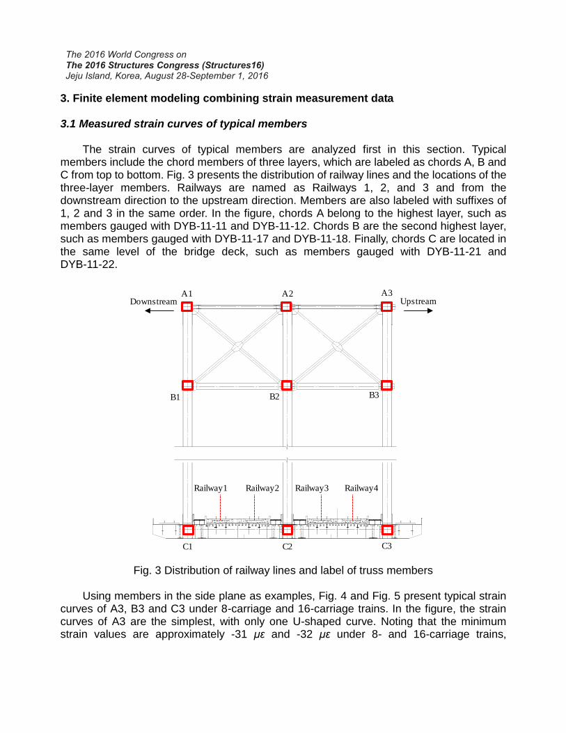
The strain curves of typical members are analyzed first in this section. Typical members include the chord members of three layers, which are labeled as chords A, B and C from top to bottom. Fig. 3 presents the distribution of railway lines and the locations of the three-layer members. Railways are named as Railways 1, 2, and 3 and from the downstream direction to the upstream direction. Members are also labeled with suffixes of 1, 2 and 3 in the same order. In the figure, chords A belong to the highest layer, such as members gauged with DYB-11-11 and DYB-11-12. Chords B are the second highest layer, such as members gauged with DYB-11-17 and DYB-11-18. Finally, chords C are located in the same level of the bridge deck, such as members gauged with DYB-11-21 and DYB-11-22.
A1 A2 A3
B1 B2 B3
C1 C2 C3
Railway1 Railway2 Railway3 Railway4
Downstream Upstream
Fig. 3 Distribution of railway lines and label of truss members Using members in the side plane as examples, Fig. 4 and Fig. 5 present typical strain
curves of A3, B3 and C3 under 8-carriage and 16-carriage trains. In the figure, the strain curves of A3 are the simplest, with only one U-shaped curve. Noting that the minimum strain values are approximately -31 με and -32 με under 8- and 16-carriage trains,
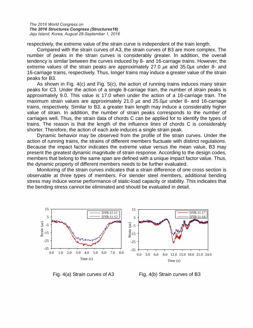
respectively, the extreme value of the strain curve is independent of the train length. Compared with the strain curves of A3, the strain curves of B3 are more complex. The
number of peaks in the strain curves is considerably greater. In addition, the overall tendency is similar between the curves induced by 8- and 16-carriage trains. However, the extreme values of the strain peaks are approximately 27.0 με and 35.0με under 8- and 16-carriage trains, respectively. Thus, longer trains may induce a greater value of the strain peaks for B3.
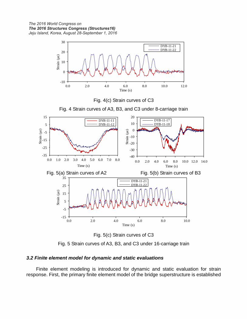
As shown in Fig. 4(c) and Fig. 5(c), the action of running trains induces many strain peaks for C3. Under the action of a single 8-carriage train, the number of strain peaks is approximately 9.0. This value is 17.0 when under the action of a 16-carriage train. The maximum strain values are approximately 21.0 με and 25.0με under 8- and 16-carriage trains, respectively. Similar to B3, a greater train length may induce a considerably higher value of strain. In addition, the number of strain peaks corresponds to the number of carriages well. Thus, the strain data of chords C can be applied for to identify the types of trains. The reason is that the length of the influence lines of chords C is considerably shorter. Therefore, the action of each axle induces a single strain peak.
Dynamic behavior may be observed from the profile of the strain curves. Under the action of running trains, the strains of different members fluctuate with distinct regulations. Because the impact factor indicates the extreme value versus the mean value, B3 may present the greatest dynamic magnitude of strain response. According to the design codes, members that belong to the same span are defined with a unique impact factor value. Thus, the dynamic property of different members needs to be further evaluated.
Monitoring of the strain curves indicates that a strain difference of one cross section is observable at three types of members. For slender steel members, additional bending stress may induce worse performance of static-load capacity or stability. This indicates that the bending stress cannot be eliminated and should be evaluated in detail.
-35
-25
-15
-5
5
15
1 51 101 151 201 251 301 351 401
Str
ain
(μ
ε)
Samples
DYB-11-11
DYB-11-12
-35
-25
-15
-5
5
15
1 151 301 451 601 751 901 1051 1201
Str
ain (
με)
Samples
DYB-11-17
DYB-11-18
0.0 1.0 2.0 3.0 4.0 5.0 6.0 7.0 8.0
Time (s)0.0 3.0 6.0 9.0 12.0 15.0 18.0 21.0 24.0
Time (s)
Fig. 4(a) Strain curves of A3 Fig. 4(b) Strain curves of B3
-10
0
10
20
30
1 51 101 151 201 251 301
Str
ain
(μ
ε)
Samples
DYB-11-21
DYB-11-22
0.0
Time (s)
2.0 4.0 6.0 8.0 10.0 12.0
Fig. 4(c) Strain curves of C3
Fig. 4 Strain curves of A3, B3, and C3 under 8-carriage train
-35
-25
-15
-5
5
15
1 51 101 151 201 251 301 351 401
Str
ain (
με)
Samples
DYB-11-11
DYB-11-12
0.0 1.0 2.0 3.0 4.0 5.0 6.0 7.0 8.0
Time (s)
-40
-30
-20
-10
0
10
20
1 201 401 601 801 1001 1201 1401
Str
ain
(μ
ε)
Samples
DYB-11-17
DYB-11-18
0.0 2.0 4.0 6.0 8.0 10.0 12.0 14.0
Time (s)
Fig. 5(a) Strain curves of A2 Fig. 5(b) Strain curves of B3
-15
-5
5
15
25
35
1 101 201 301 401 501
Str
ain
(μ
ε)
Samples
DYB-11-21
DYB-11-22
0.0
Time (s)
2.0 4.0 6.0 8.0 10.0
Fig. 5(c) Strain curves of C3
Fig. 5 Strain curves of A3, B3, and C3 under 16-carriage train
3.2 Finite element model for dynamic and static evaluations
Finite element modeling is introduced for dynamic and static evaluation for strain response. First, the primary finite element model of the bridge superstructure is established
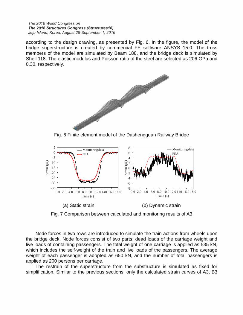
according to the design drawing, as presented by Fig. 6. In the figure, the model of the bridge superstructure is created by commercial FE software ANSYS 15.0. The truss members of the model are simulated by Beam 188, and the bridge deck is simulated by Shell 118. The elastic modulus and Poisson ratio of the steel are selected as 206 GPa and 0.30, respectively.
Fig. 6 Finite element model of the Dashengguan Railway Bridge
0.0
-35
-30
-25
-20
-15
-10
-5
0
5
1 101 201 301 401 501 601 701 801 901
Sre
ain (
μξ)
Samples
Monitoring data
FEA
-8
-6
-4
-2
0
2
4
6
8
1 101 201 301 401 501 601 701 801 901
Sre
ain
(μ
ξ)
Samples
Monitoring data
FEA
Str
ain
(μ
ζ)
Str
ain
(μ
ζ)
Time (s)
2.0 4.0 6.0 8.0 10.0 12.0 140 16.0 18.0 0.0
Time (s)
2.0 4.0 6.0 8.0 10.0 12.0 140 16.0 18.0
(a) Static strain (b) Dynamic strain
Fig. 7 Comparison between calculated and monitoring results of A3
Node forces in two rows are introduced to simulate the train actions from wheels upon
the bridge deck. Node forces consist of two parts: dead loads of the carriage weight and live loads of containing passengers. The total weight of one carriage is applied as 535 kN, which includes the self-weight of the train and live loads of the passengers. The average weight of each passenger is adopted as 650 kN, and the number of total passengers is applied as 200 persons per carriage.
The restrain of the superstructure from the substructure is simulated as fixed for simplification. Similar to the previous sections, only the calculated strain curves of A3, B3
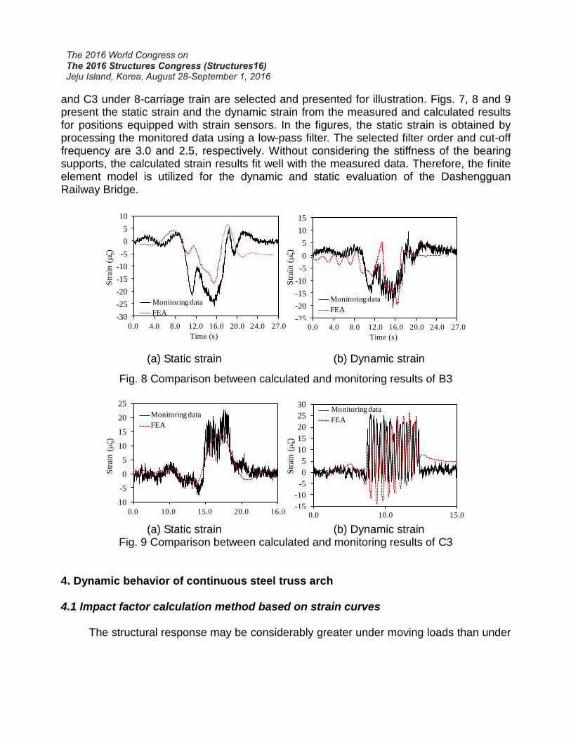
and C3 under 8-carriage train are selected and presented for illustration. Figs. 7, 8 and 9 present the static strain and the dynamic strain from the measured and calculated results for positions equipped with strain sensors. In the figures, the static strain is obtained by processing the monitored data using a low-pass filter. The selected filter order and cut-off frequency are 3.0 and 2.5, respectively. Without considering the stiffness of the bearing supports, the calculated strain results fit well with the measured data. Therefore, the finite element model is utilized for the dynamic and static evaluation of the Dashengguan Railway Bridge.
-30
-25
-20
-15
-10
-5
0
5
10
1 201 401 601 801 1001 1201 1401
Sre
ain
(μξ)
Samples
Monitoring data
FEA-25
-20
-15
-10
-5
0
5
10
15
1 201 401 601 801 1001 1201 1401
Sre
ain
(μξ)
Samples
Monitoring data
FEA
Monitoring dataMonitoring data
FEA
Str
ain (
μζ)
Str
ain (
μζ)
0.0
Time (s)
4.0 8.0 12.0 16.0 20.0 24.0 27.0 0.0
Time (s)
4.0 8.0 12.0 16.0 20.0 24.0 27.0
(a) Static strain (b) Dynamic strain
Fig. 8 Comparison between calculated and monitoring results of B3
Time (s) Time (s)
-10
-5
0
5
10
15
20
25
1 501 1001 1501 2001
Sre
ain (
μξ)
Samples
-15
-10
-5
0
5
10
15
20
25
30
1 501 1001
Sre
ain (
μξ)
Samples
FEA
Str
ain (
μζ)
Str
ain (
μζ)
Monitoring dataMonitoring data
FEA
0.0 10.0 15.0 20.0 16.0 0.0 10.0 15.0 (a) Static strain (b) Dynamic strain
Fig. 9 Comparison between calculated and monitoring results of C3 4. Dynamic behavior of continuous steel truss arch 4.1 Impact factor calculation method based on strain curves
The structural response may be considerably greater under moving loads than under
static loads with a similar value. This phenomenon is the so-called dynamic behavior of a structure. The impact factor is generally applied to profile the dynamic behavior of a structure by comparing the structural stress under a dynamic load with the responses under an equivalent static load.23 The impact factor is generally defined as follows:
DLADLF 1 (1) where DLF denotes the dynamic load factor and DLA denotes the dynamic load allowance given by
s t a t
s t a td y n
R
RRD L A
(2)
where Rdyn denotes the maximum amplitude of dynamic strain data and Rstat denotes the maximum amplitude of static strain data.
The measured strain data consist of static load-induced strain and the dynamic amplitude. Based on the distinction of frequency between dynamic and static strain data, a low-pass filter is applied to eliminate the dynamic components of strain data and obtain the static component. The selected filter order and cut-off frequency are 3.0 and 2.5, respectively. The impact factor can be calculated by applying equations (1) and (2). For finite element evaluation, the factor can be directly obtained by comparison of the dynamic and static calculations. Taking the 8-carriage train with a speed of 240 km/h as an example, the impact factors are calculated under four different railways for three types of members. In addition, monitoring strain data of trains with a speed of approximately 240 km/h are selected to calculate the impact factor. Table 1 presents the average impact factors calculated using the monitoring strain data and the finite element evaluations. As shown in this table, the calculated impact factors of A3, B3 and C3 correspond well with the monitoring data. Based on the finite element model, further investigation is conducted to acquire the dynamic behavior of the bridge superstructure.
Table 1 Comparison of impact factors between the theoretical and monitoring results
Member
Railway 1 Railway 2 Railway 3 Railway 4 Monitoring results
Calculated results
Monitoring results
Calculated results
Monitoring results
Calculated results
Monitoring results
Calculated results
A3 1.0067 1.0074 1.0062 1.0069 1.0058 1.0067 1.0055 1.0064 B3 1.0565 1.0596 1.0502 1.0546 1.0428 1.0487 1.0285 1.0365 C3 1.0067 1.0121 1.0089 1.0109 1.0094 1.0096 1.0105 1.0074
4.2 Dynamic behavior of the main truss members
Table 1 also shows that the impact factors of different members are distinct. Among the three different members, the impact factor of B3 is the greatest, reaching almost 1.06. A3 possesses the lowest impact factor value. Thus, the member of chords B should be given more attention. Additionally, the table also shows that the impact factor value is significantly affected by the positions of the railways. With the transverse positions of running trains approaching the truss members, the impact factor is considerably greater. However, the
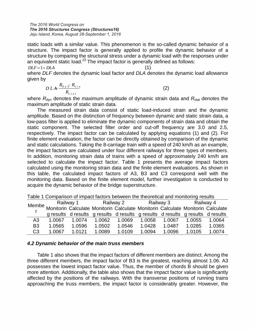
difference of impact factors between trains in different railways is not very great. An investigation is also conducted to obtain the influence of train length on the impact
factor. Assuming that the speed of the train is 240 km/m, Fig. 10 presents the calculated results of the impact factors for 8- and 16-carriage running trains. As shown in this figure, a greater number of carriages induces a smaller impact factor for all three types of members. However, the influence of train length is limited. For chord B3, whose impact factor is the most sensitive to the train length, the greatest difference between the two types of trains is only approximately 0.03.
1.000
1.002
1.004
1.006
1.008
1.010
Railway 1 Railway 2 Railway 3 Railway 4
Cal
cula
ted
Im
pac
t fa
cto
r
Transverse position of train
8-carrage 16-carrage
1.000
1.020
1.040
1.060
1.080
1.100
1.120
1.140
Railway 1 Railway 2 Railway 3 Railway 4
Cal
cula
ted I
mp
act
fact
or
Transverse position of train
8-carrage 16-carrage
(a) Chord A3 (b) Chord B3
1.000
1.010
1.020
1.030
1.040
1.050
Railway 1 Railway 2 Railway 3 Railway 4
Cal
cula
ted
Im
pac
t fa
cto
r
Transverse position of train
8-carrage 16-carrage
(c) Chord C3
Fig. 10 Impact factors under different numbers of train carriages
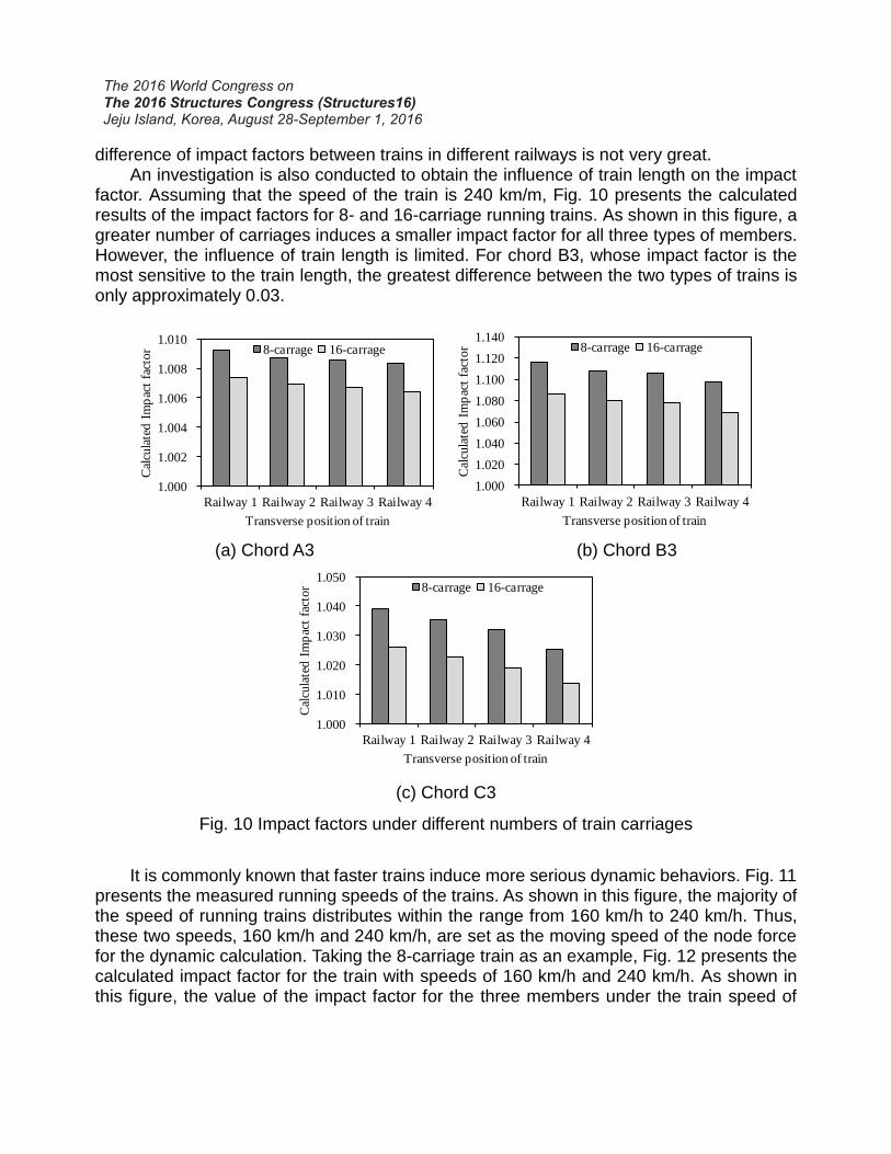
It is commonly known that faster trains induce more serious dynamic behaviors. Fig. 11
presents the measured running speeds of the trains. As shown in this figure, the majority of the speed of running trains distributes within the range from 160 km/h to 240 km/h. Thus, these two speeds, 160 km/h and 240 km/h, are set as the moving speed of the node force for the dynamic calculation. Taking the 8-carriage train as an example, Fig. 12 presents the calculated impact factor for the train with speeds of 160 km/h and 240 km/h. As shown in this figure, the value of the impact factor for the three members under the train speed of
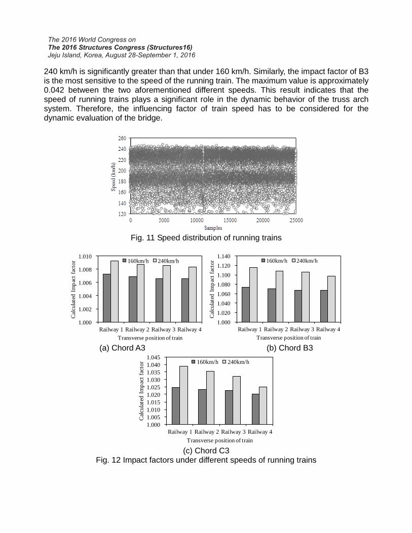
240 km/h is significantly greater than that under 160 km/h. Similarly, the impact factor of B3 is the most sensitive to the speed of the running train. The maximum value is approximately 0.042 between the two aforementioned different speeds. This result indicates that the speed of running trains plays a significant role in the dynamic behavior of the truss arch system. Therefore, the influencing factor of train speed has to be considered for the dynamic evaluation of the bridge.
Fig. 11 Speed distribution of running trains
1.000
1.002
1.004
1.006
1.008
1.010
Railway 1 Railway 2 Railway 3 Railway 4
Cal
cula
ted I
mp
act
fact
or
Transverse position of train
160km/h 240km/h
1.000
1.020
1.040
1.060
1.080
1.100
1.120
1.140
Railway 1 Railway 2 Railway 3 Railway 4
Cal
cula
ted I
mp
act
fact
or
Transverse position of train
160km/h 240km/h
(a) Chord A3 (b) Chord B3
1.000
1.005
1.010
1.015
1.020
1.025
1.030
1.035
1.040
1.045
Railway 1 Railway 2 Railway 3 Railway 4
Cal
cula
ted I
mp
act
fact
or
Transverse position of train
160km/h 240km/h
(c) Chord C3
Fig. 12 Impact factors under different speeds of running trains
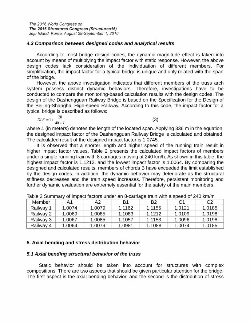
4.3 Comparison between designed codes and analytical results
According to most bridge design codes, the dynamic magnitude effect is taken into account by means of multiplying the impact factor with static response. However, the above design codes lack consideration of the individuation of different members. For simplification, the impact factor for a typical bridge is unique and only related with the span of the bridge.
However, the above investigation indicates that different members of the truss arch system possess distinct dynamic behaviors. Therefore, investigations have to be conducted to compare the monitoring-based calculation results with the design codes. The design of the Dashengguan Railway Bridge is based on the Specification for the Design of the Beijing-Shanghai High-speed Railway. According to this code, the impact factor for a typical bridge is described as follows:
LDLF
40
281 (3)
where L (in meters) denotes the length of the located span. Applying 336 m in the equation, the designed impact factor of the Dashengguan Railway Bridge is calculated and obtained. The calculated result of the designed impact factor is 1.0745.
It is observed that a shorter length and higher speed of the running train result in higher impact factor values. Table 2 presents the calculated impact factors of members under a single running train with 8 carriages moving at 240 km/h. As shown in this table, the highest impact factor is 1.1212, and the lowest impact factor is 1.0064. By comparing the designed and calculated results, members of chords B have exceeded the limit established by the design codes. In addition, the dynamic behavior may deteriorate as the structural stiffness decreases and the train speed increases. Therefore, persistent monitoring and further dynamic evaluation are extremely essential for the safety of the main members. Table 2 Summary of impact factors under an 8-carriage train with a speed of 240 km/m
Member A1 A2 B1 B2 C1 C2
Railway 1 1.0074 1.0079 1.1162 1.1155 1.0121 1.0185
Railway 2 1.0069 1.0085 1.1083 1.1212 1.0109 1.0198
Railway 3 1.0067 1.0085 1.1057 1.1153 1.0096 1.0198
Railway 4 1.0064 1.0079 1.0981 1.1088 1.0074 1.0185
5. Axial bending and stress distribution behavior 5.1 Axial bending structural behavior of the truss
Static behavior should be taken into account for structures with complex
compositions. There are two aspects that should be given particular attention for the bridge. The first aspect is the axial bending behavior, and the second is the distribution of stress
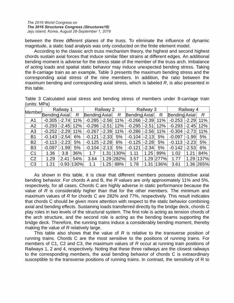
between the three different planes of the truss. To eliminate the influence of dynamic magnitude, a static load analysis was only conducted on the finite element model.
According to the classic arch truss mechanism theory, the highest and second highest chords sustain axial forces that induce similar fiber strains at different edges. An additional bending moment is adverse for the stress state of the member of the truss arch. Imbalance of acting loads and spatial static behavior may induce unexpected bending stress. Taking the 8-carriage train as an example, Table 3 presents the maximum bending stress and the corresponding axial stress of the nine members. In addition, the ratio between the maximum bending and corresponding axial stress, which is labeled R, is also presented in this table.
Table 3 Calculated axial stress and bending stress of members under 8-carriage train (units: MPa)
Member Railway 1 Railway 2 Railway 3 Railway 4
Bending Axial R Bending Axial R Bending Axial R Bending Axial R
A1 -0.305 -2.74 11% -0.285 -2.56 11% -0.266 -2.39 11% -0.253 -2.29 11%
A2 -0.293 -2.45 12% -0.296 -2.51 12% -0.295 -2.51 12% -0.293 -2.45 12%
A3 -0.252 -2.29 11% -0.267 -2.39 11% -0.286 -2.56 11% -0.304 -2.73 11%
B1 -0.143 -2.54 6% -0.121 -2.33 5% -0.104 -2.13 5% -0.097 -1.99 5%
B2 -0.113 -2.23 5% -0.125 -2.28 6% -0.125 -2.28 5% -0.113 -2.23 5%
B3 -0.097 -1.99 5% -0.104 -2.13 5% -0.121 -2.34 5% -0.142 -2.53 6%
C1 1.36 3.8 36% 1.7 1.31 130% 1.11 1.25 89% 1.02 1.21 84%
C2 1.29 2.41 54% 3.64 1.29 282% 3.57 1.29 277% 1.77 1.29 137%
C3 1.21 0.93 130% 1.1 1.25 88% 1.78 1.31 136% 3.61 1.36 265%
As shown in this table, it is clear that different members possess distinctive axial
bending behavior. For chords A and B, the R values are only approximately 11% and 5%, respectively, for all cases. Chords C are highly adverse in static performance because the value of R is considerably higher than that for the other members. The minimum and maximum values of R for chords C are 282% and 77%, respectively. This result indicates that chords C should be given more attention with respect to the static behavior combining axial and bending effects. Sustaining loads transferred directly by the bridge deck, chords C play roles in two levels of the structural system. The first role is acting as tension chords of the arch structure, and the second role is acting as the bending beams supporting the bridge deck. Therefore, the running trains induce a considerably bending moment, thereby making the value of R relatively large.
This table also shows that the value of R is relative to the transverse position of running trains. Chords C are the most sensitive to the positions of running trains. For members of C1, C2 and C3, the maximum values of R occur at running train positions of Railways 1, 2 and 4, respectively. Noting that these three railways are the closest railways to the corresponding members, the axial bending behavior of chords C is extraordinary susceptible to the transverse positions of running trains. In contrast, the sensitivity of R to
the transverse positions of running trains is considerably smaller for chords A and B. The distinction among the four different railways is small enough to be neglected.
Although the value of R is relatively great for typical members such as chords C, the level of bending and axial stress induced by running train is not more than 4 MPa. Noting that the ultimate tensile strength of steel material is 370 MPa, the axial-bending performance of main members is far lower. It consequently indicates that the axial-bending behavior is not crucial factor for static behavior of the bridge.
5.2 Stress distribution between three planes of truss
In addition to the axial bending behavior, another concern for the arch truss system is the stress distribution between the three planes of the truss. Among the three types of members mentioned above, chords A and B are typical members of the arch truss system that sustain high-level axial compression stress. Therefore, chords A and B are selected for static behavior evaluation of stress distribution. In addition, axial compression stress is selected as the factor for investigating the stress distribution behavior because of its significance of static behavior.
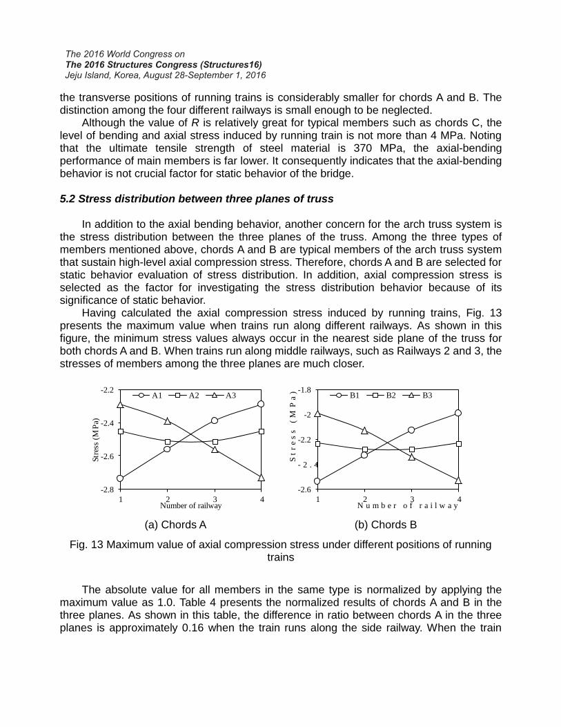
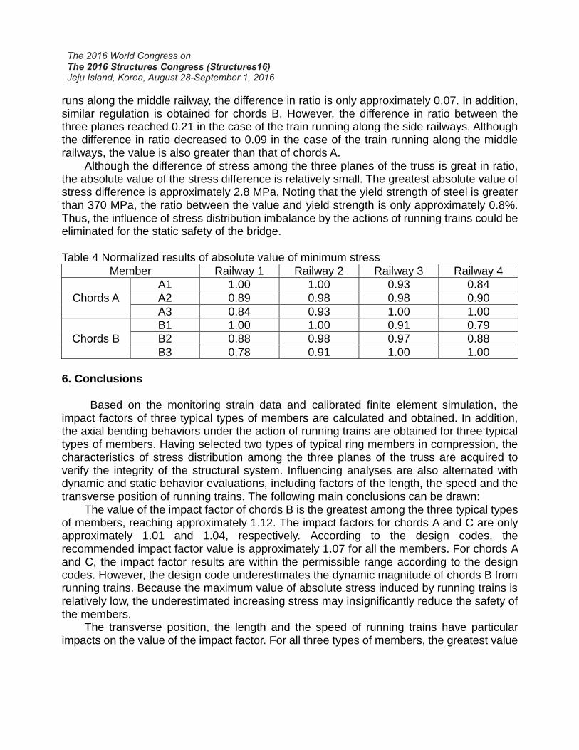
Having calculated the axial compression stress induced by running trains, Fig. 13 presents the maximum value when trains run along different railways. As shown in this figure, the minimum stress values always occur in the nearest side plane of the truss for both chords A and B. When trains run along middle railways, such as Railways 2 and 3, the stresses of members among the three planes are much closer.
-2.8
-2.6
-2.4
-2.2
1 2 3 4
Str
ess
(MP
a)
Number of railway
A1 A2 A3
-2.6
- 2 . 4
-2.2
-2
-1.8
1 2 3 4
St
re
ss
(
MP
a)
N u m b e r o f r a i l w a y
B1 B2 B3
(a) Chords A (b) Chords B
Fig. 13 Maximum value of axial compression stress under different positions of running trains
The absolute value for all members in the same type is normalized by applying the
maximum value as 1.0. Table 4 presents the normalized results of chords A and B in the three planes. As shown in this table, the difference in ratio between chords A in the three planes is approximately 0.16 when the train runs along the side railway. When the train
runs along the middle railway, the difference in ratio is only approximately 0.07. In addition, similar regulation is obtained for chords B. However, the difference in ratio between the three planes reached 0.21 in the case of the train running along the side railways. Although the difference in ratio decreased to 0.09 in the case of the train running along the middle railways, the value is also greater than that of chords A.
Although the difference of stress among the three planes of the truss is great in ratio, the absolute value of the stress difference is relatively small. The greatest absolute value of stress difference is approximately 2.8 MPa. Noting that the yield strength of steel is greater than 370 MPa, the ratio between the value and yield strength is only approximately 0.8%. Thus, the influence of stress distribution imbalance by the actions of running trains could be eliminated for the static safety of the bridge. Table 4 Normalized results of absolute value of minimum stress
Member Railway 1 Railway 2 Railway 3 Railway 4
Chords A
A1 1.00 1.00 0.93 0.84
A2 0.89 0.98 0.98 0.90
A3 0.84 0.93 1.00 1.00
Chords B
B1 1.00 1.00 0.91 0.79
B2 0.88 0.98 0.97 0.88
B3 0.78 0.91 1.00 1.00
6. Conclusions
Based on the monitoring strain data and calibrated finite element simulation, the impact factors of three typical types of members are calculated and obtained. In addition, the axial bending behaviors under the action of running trains are obtained for three typical types of members. Having selected two types of typical ring members in compression, the characteristics of stress distribution among the three planes of the truss are acquired to verify the integrity of the structural system. Influencing analyses are also alternated with dynamic and static behavior evaluations, including factors of the length, the speed and the transverse position of running trains. The following main conclusions can be drawn:
The value of the impact factor of chords B is the greatest among the three typical types of members, reaching approximately 1.12. The impact factors for chords A and C are only approximately 1.01 and 1.04, respectively. According to the design codes, the recommended impact factor value is approximately 1.07 for all the members. For chords A and C, the impact factor results are within the permissible range according to the design codes. However, the design code underestimates the dynamic magnitude of chords B from running trains. Because the maximum value of absolute stress induced by running trains is relatively low, the underestimated increasing stress may insignificantly reduce the safety of the members.
The transverse position, the length and the speed of running trains have particular impacts on the value of the impact factor. For all three types of members, the greatest value
of impact factor occurs when the trains run along the nearest railways. The impact factor induced by trains with 8 carriages is greater than that induced by trains with 16 carriages. In addition, the relation between the impact factor and speed of running trains is also significant, with a higher speed of trains inducing more serious dynamic behavior.
Although the level of train-induced bending stress is considerably lower than the actual axial stress considering the dead loads, the ratio of train-induced bending versus train-induced axial stress, which is labeled R, is relatively large. Different members exhibit distinct axial bending behaviors. Chords C present the greatest value of R compared with the other two members with a maximum value of 3.37. Compared with chords C, chords A and B present smaller values of R, with the maximum values only reaching 0.12 and 0.06, respectively. In addition, only chords C are significantly influenced by the transverse positions of trains. Closer positions of the running trains induce higher values of R. Moreover, the difference ratio between the four railways could be approximately 200% for chords C.
Distinct stresses induced by trains exist among the three planes of the truss. The greatest value of difference ratio is approximately 16% and 22% for chords A and B. When trains run along the middle railways, the difference of stress among the three planes is the smallest, with the difference ratio being only approximately 7%. However, the influence of stress imbalance may insignificantly induce static behavior because the train-induced stress is far less than the yield strength of the steel material.
Conflicts of interest
The authors declare that there are no conflicts of interest regarding the publication of this paper. Acknowledgements
The authors gratefully acknowledge the National Basic Research Program of China (973 Program) (no. 2015CB060000), the National Science and Technology Support Program of China (no. 2014BAG07B01), the Key Program of National Natural Science Foundation (no. 51438002), the Program of National Natural Science Foundation (no. 51578138, 51508251), the Program of ―Six Major Talent Summit‖ Foundation (no. 1105000268), the Natural Science Fund for Colleges and Universities in Jiangsu Province (no. 15KJB560005), the Fundamental Research Funds for the Central Universities and the Innovation Plan Program for Ordinary University Graduates of Jiangsu Province in 2014 (No. KYLX_0156) and the Scientific Research Foundation of Graduate School of Southeast University (No.YBJJ1441).
References 1. Hu N, Dai G, Yan B, et al. Recent development of design and construction of medium
and long span high-speed railway bridges in China. Eng Struct 2014; 74: 233-241. doi: 10.1016/j.engstruct.2014.05.052.
2. Qin SQ. Large span bridges on high speed railway lines. J Rail Eng Soc 2008; 10: 53-61.
3. Dai G, Hu N, Liu W. The recent improvement of high-speed railway bridges in China. Int Assoc Bridge Struct Eng 2010; 97: 8-15. doi: 10.2749/222137810796024132.
4. Kwark JW, Choi ES, Kim YJ, et al. Dynamic behavior of two-span continuous concrete bridges under moving high-speed train. Comput Struct 2004; 82: 463-467. doi: 10.1016/S0045-7949(03)00054-3.
5. Frýba L. A rough assessment of railway bridges for high speed trains. Eng Struct 2001; 23: 548-556.
6. Xia H, Zhang N, De Roeck G. Dynamic analysis of high speed railway bridge under articulated trains. Comput Struct, 2003; 81: 2467–2478. doi: 10.1016/S0045-7949(03)00309-2.
7. Raghunathan RS, Kim HD, Setoguchi T. Aerodynamics of high-speed railway train. Prog Aerosp. Sci 2002; 38: 469–514. doi: 10.1016/S0376-0421(02)00029-5.
8. Dias R, Goicolea Ruigómez JM, Gabaldón Castillo F, et al. A study of the lateral dynamic behaviour of high speed railway viaducts and its effect on vehicle ride comfort and stability. In: IABMA08: Fourth International Conference on Bridge Maintenance, Safety and Management, Seúl, Corea, 13 July-17 July 2008.
9. Calcada R, Delgado R, Campos e Matos A, et al. Track-Bridge Interaction on High-Speed Railways: Selected and revised papers from the Workshop on Track-Bridge Interaction on High-Speed Railways, Porto, Portugal, 15–16 October, 2007. Boca Raton, FL: CRC Press, 2007.
10. Fitzwilliam D. Track structure interactions for the Taiwan high speed rail project IABSE symposium report. Int Assoc Bridge Struct Eng 2003; 87: 10.
11. Dutoit D. New evolutions for high speed rail line bridge design criteria and corresponding design procedures IABSE symposium report. Int Assoc Bridge Struct Eng 2003; 87: 12.
12. Kristek V, Vrablik L. Optimisation of tendon layout to avoid excessive deflections of long-span prestressed concrete bridges. Concrete Eng., 2007; 11: 30–33.
13. Fiore A, Foti D, Monaco P, et al. An approximate solution for the rheological behavior of non-homogeneous structures changing the structural system during the construction process. Eng Struct 2013; 46: 631–642. doi: 10.1016/j.engstruct.2012.08.014.
14. Kumar R, Upadhyay A. Effect of temperature gradient on track-bridge interaction. Interact Multiscale Mech 2012; 5: 1–12. doi: 10.12989/imm.2012.5.1.001.
15. Dong HX. Force analysis of large continuous beam bridge with Arch. M.S. Dissertation, Central South University, 2009 (in Chinese).
16. Feng D, Feng MQ. Model updating of railway bridge using in situ dynamic displacement measurement under trainloads. J Bridge Eng 2015; 20: 04015019. doi:
10.1061/(ASCE)BE.1943-5592.0000765. 17. Deng L, Yu Y, Zou Q, et al. State-of-the-Art review of dynamic impact factors of highway
bridges. J Bridge Eng 2015; 20: 1943-5592. doi: 10.1061/(ASCE)BE.1943-5592.0000672.
18. Lee H, Jeon J, Kyung K. Determination of a reasonable impact factor for fatigue investigation of simple steel plate girder railway bridges. Eng Struct 2012; 36: 316-324. doi: 10.1016/j.engstruct.2011.12.021.
19. Deng L, Cai CS. Development of dynamic impact factor for performance evaluation of
existing multi-girder concrete bridges. Eng Struct 2010; 32: 21-31. doi: 10.1016/j.engstruct.2009.08.013.
20. Ashebo DB, Chan THT, Yu L. Evaluation of dynamic loads on a skew box girder continuous bridge part II: parametric study and dynamic load factor. Eng Struct 2007; 29: 1064-1073. doi: 10.1016/j.engstruct.2006.07.013.
21. Zhang X, Sennah K, Kennedy JB. Evaluation of impact factors for composite concrete–steel cellular straight bridges. Eng Struct 2003; 25: 313-321. doi: 10.1016/S0141-0296(02)00160-8.
22. Ye MX, Zhang M, Han YQ. Mechanical characteristics of three-truss continuous steeltruss arch- girder bridges on high-speed railways. J Huazhong Univ Sci Tech 2010; 38: 96-99. (in Chinese).
23. Bakht B, Pinjarkar SG. Dynamic testing of highway bridges—a review. Transp Res Rec 1989; 1223: 93–100.