Embed Size (px)
Citation preview
Engineering Fracture Mechanics xxx (2014) xxx–xxx
Contents lists available at ScienceDirect
Engineering Fracture Mechanics
journal homepage: www.elsevier .com/locate /engfracmech
Stress intensity factor solutions for adhesive-bonded lap-shearspecimens of magnesium and steel sheets with and withoutkinked cracks for fatigue life estimations
http://dx.doi.org/10.1016/j.engfracmech.2014.09.0020013-7944/� 2014 Elsevier Ltd. All rights reserved.
⇑ Corresponding author. Tel.: +1 734 764 9404; fax: +1 734 647 3170.E-mail addresses: [email protected] (W.-J. Lai), [email protected] (J. Pan).
Please cite this article in press as: Lai W-J, Pan J. Stress intensity factor solutions for adhesive-bonded lap-shear specimens of magand steel sheets with and without kinked cracks for fatigue life estimations. Engng Fract Mech (2014), http://dx.doi.org/1j.engfracmech.2014.09.002
Wei-Jen Lai a, Jwo Pan b,⇑a Department of Materials Science and Engineering, The University of Michigan, Ann Arbor, MI 48109, USAb Department of Mechanical Engineering, The University of Michigan, Ann Arbor, MI 48109, USA
a r t i c l e i n f o a b s t r a c t
Article history:Received 9 May 2014Received in revised form 24 August 2014Accepted 2 September 2014Available online xxxx
Keywords:Adhesive-bonded jointDissimilar jointLap-shear specimenStress intensity factor solutionKinked crackFatigue life estimation
In this paper, stress intensity factor solutions for adhesive-bonded lap-shear specimens ofmagnesium alloy AZ31 and hot-dip-galvanized (HDG) mild steel sheets with and withoutkinked cracks are investigated for fatigue life estimations. First, the kinked fatigue crackfailure mode of the adhesive-bonded lap-shear specimens is briefly reviewed. Then, theanalytical global J integral and effective stress intensity factor solutions for main cracksin lap-shear specimens of three dissimilar sheets under plane strain conditions are devel-oped based on the beam bending theory. The global effective stress intensity factor solu-tions for the main cracks in the lap-shear specimens from the corresponding finiteelement analyses are then presented and validated by the analytical solutions. Next, thelocal stress intensity factor solutions for kinked cracks with the experimentally observedkink angle as functions of the kink length from the corresponding finite element analysesare presented and the computational solutions are also compared with the analytical solu-tions at small kink lengths. The results indicate that the computational local stress inten-sity factor solutions for kinked cracks approach to the analytical solutions as the kinklength decreases to a small value and the kinked crack is under dominant mode I loadingconditions. The computational results also indicate that the local stress intensity factorsolutions at a small kink length of microstructural significance may be used as the stressintensity factor solutions for zero or near zero kink length for fatigue life estimations whenthe computational results are not available. The computational local stress intensity factorsolutions are then adopted to estimate the fatigue lives of the lap-shear specimens basedon a kinked crack growth model and available material constants for the Paris law. The fati-gue life estimations are lower than the experimental results. However, the general trend offatigue life estimations agrees with that of the experimental results.
� 2014 Elsevier Ltd. All rights reserved.
1. Introduction
Lightweight materials such as advanced high strength steels, aluminum, and magnesium alloys have been replacing thetraditional steel in the automotive industry to reduce the vehicle weight. Since magnesium alloys are much lighter than thesteels commonly used in vehicles, using magnesium alloys could result in a substantial weight reduction. One of the major
nesium0.1016/
Nomenclature
HDG hot-dip-galvanizedb specimen widthL sheet lengthtu thickness of sheet utl1 thickness of sheet l1tl2 thickness of sheet l2V specimen overlap lengthw bonded widthE Young’s modulusG shear modulusm Poisson’s ratior normal stressJ J integralW strain energy density functionWj strain energy density function for sheet jC J integration contourds differential arc length for the contour Cn unit outward normalnx x component of the unit outward normal nT traction vectorTi(=rijnj) components of the traction vector Tu displacement vectorui components of the displacement vector urij stress componentseij strain componentsE0 Young’s modulus under plane stress or plane strain conditionsr* normal structural stress to satisfy the equilibrium, and continuity of the strain and strain gradientdu ratio of the sheet u thickness to the total sheet thicknessdl1 ratio of the sheet l1 thickness to the total sheet thicknessdl2 ratio of the sheet l2 thickness to the total sheet thicknesst total thickness of sheets u, l1 and l2gu1 modulus ratio of sheet u to sheet l1g12 modulus ratio of sheet l1 to sheet l2D constant defined in Eq. (39)Nj constants defined in Eqs. (18)–(38)Cijmnl constants defined in Eq. (40)h angle between the loading direction and the x directiond distance from the load application point to the nearest main crack tipF applied loadKe global effective stress intensity factorK(=K1 + iK2) complex stress intensity factor for an interface crackry normal stress in the y directionsxy shear stress with respect to the x and y directionstc characteristic lengthr small distance ahead of an interface crack tipe bimaterial constantju constant defined in Eq. (49)jl1 constant defined in Eq. (50)jl2 constant defined in Eq. (52)E* constant defined in Eqs. (54) and (55)KI, KII conventional mode I and II stress intensity factors
KA ¼ KA1 þ iKA
2
� �complex stress intensity factor for an interface crack obtained from ABAQUS
F1, F2, Fe dimensionless geometric functions for main cracksa kink lengthu kink anglekI, kII local stress intensity factorske local effective stress intensity factora, b Dundurs’ parametersc, d complex functions of a, b and u
2 W.-J. Lai, J. Pan / Engineering Fracture Mechanics xxx (2014) xxx–xxx
Please cite this article in press as: Lai W-J, Pan J. Stress intensity factor solutions for adhesive-bonded lap-shear specimens of magnesiumand steel sheets with and without kinked cracks for fatigue life estimations. Engng Fract Mech (2014), http://dx.doi.org/10.1016/j.engfracmech.2014.09.002
fI, fII, fe dimensionless geometric functions for kinked crackskeq equivalent stress intensity factor for the Paris lawc material constant for the Paris lawN number of cyclesC material constant for the Paris lawm material constant for the Paris law
Subscripts and superscriptsu, l1, l2 upper sheet, lower sheet 1, and lower sheet 2i, o inner and outer surfaces of the sheets with respect to the main crack
W.-J. Lai, J. Pan / Engineering Fracture Mechanics xxx (2014) xxx–xxx 3
issues for introducing magnesium alloys into vehicle structures appears to be joining magnesium components to the existingsteel structures. Joining magnesium alloys to steels is especially difficult due to the extreme difference in their melting tem-peratures and immiscibility of magnesium and iron [1]. Melting magnesium alloys and steels together as might be done inresistance spot welding would vaporize magnesium and create unacceptable porosity in the weld nugget.
Solid state joining of magnesium alloys and steels offers a potential solution as the melting is either avoided or mini-mized. Ultrasonic welding is capable of joining similar and dissimilar materials. For joining similar materials using ultrasonicspot welding for automotive applications, researchers conducted research on processing conditions of joining similar alumi-num sheets, for example, see Hetrick et al. [2], Jahn et al. [3] and Wright et al. [4]. For joining dissimilar sheets by ultrasonicspot welding, Watanabe et al. [5] conducted research on joining aluminum and steel sheets. Santella et al. [1] conductedresearch on joining magnesium to zinc-coated steel sheets by ultrasonic spot welding. The failure mode and fatigue behaviorof the dissimilar ultrasonic spot welds in lap-shear specimens of magnesium AZ31B-H24 and hot-dipped-galvanized mildsteel sheets were investigated by Franklin et al. [6] and Lai et al. [7] under quasi-static and cyclic loading conditions.
Lai et al. [7] explored the use of adhesive to increase the joint stiffness and to improve the fatigue performance of ultra-sonic spot welds of the magnesium and steel sheets. Lai et al. [7] applied a layer of adhesive between the magnesium andsteel sheets and ultrasonic spot welded the dissimilar sheets before the curing of the adhesive. The failure mode and fatiguebehavior of the weld-bonded joints were then compared with those of the adhesive-bonded and ultrasonic spot weldedjoints. The results indicated that the adhesive-bonded and weld-bonded joints have much higher fatigue lives at a given loadrange than those of the ultrasonic spot weld joints under cyclic lap-shear loading conditions. However, the weld-bondedjoints do not appear to provide additional fatigue lives for a given load range since the ultrasonic spot welds between themagnesium and steel sheets appear to be not strong enough to increase the fatigue lives under cyclic loading conditions.The adhesive-bonded and weld-bonded specimens of magnesium and steel sheets of Lai et al. [7] failed from the interfaceand subinterface fatigue crack growth under low-cycle loading conditions and failed from the kinked fatigue crack growththrough the magnesium sheet under high-cycle loading conditions. The ultrasonic spot welds in lap-shear specimens of mag-nesium and steel sheets also failed from the kinked fatigue crack growth through the magnesium sheets.
Franklin [8] machined the lap-shear specimens of ultrasonic spot welds of the magnesium and steel sheets into a dog-bone shaped profile. The ultrasonic welds in these dog-bone shaped lap-shear specimens of magnesium and steel sheets alsofailed from the kinked fatigue crack growth through the magnesium sheets. For fatigue life estimations of these ultrasonicwelded and adhesive-bonded specimens based on the kinked fatigue crack growth model using the Paris law, one needs toobtain the stress intensity factor solutions for kinked cracks at various kink lengths including zero or near zero kink length.For a kink crack growing out from a main crack between similar materials, the analytical solutions of Cotterell and Rice [9]can be used to calculate the stress intensity factors at zero or near zero kink length. However, analytical solutions for inter-face cracks between dissimilar materials of He and Hutchinson [10] are functions of the kink length, and the stress intensityfactor solutions for kinked cracks growing out from a main crack between dissimilar materials at ‘‘zero’’ kink length cannotbe determined.
In order to determine the fatigue life of the adhesive-bonded lap-shear specimen of dissimilar sheets based on a kinkedfatigue crack growth model for kinked cracks growing out from an interface between dissimilar sheets, stress intensity factorsolutions for kinked cracks with zero (or near zero) and finite kink lengths are needed. For small kink lengths, the analyticalsolution of He and Hutchinson [10] could be applicable. However, the range of the kink length, where the analytical stressintensity factor solutions are applicable, is not clear. For finite kink lengths, the stress intensity factor solutions can beobtained by finite element analyses. In this paper, the kinked fatigue crack failure mode of the adhesive-bonded lap-shearspecimen of Lai et al. [7] is first reviewed briefly. Then, the analytical global J integral and effective stress intensity factorsolutions for main cracks in lap-shear specimens of three dissimilar sheets under plane strain conditions are developedbased on the beam bending theory. The global effective stress intensity factor solutions for the main cracks in the lap-shearspecimens from the corresponding finite element analyses are then presented and compared with the analytical solutions.Next, the local stress intensity factor solutions for kinked cracks with the experimentally observed kink angle as functions ofthe kink length from the corresponding finite element analyses are presented. The computational results are also comparedwith the analytical solutions for small kink lengths to determine the range of the kink length where the analytical solutions
Please cite this article in press as: Lai W-J, Pan J. Stress intensity factor solutions for adhesive-bonded lap-shear specimens of magnesiumand steel sheets with and without kinked cracks for fatigue life estimations. Engng Fract Mech (2014), http://dx.doi.org/10.1016/j.engfracmech.2014.09.002
4 W.-J. Lai, J. Pan / Engineering Fracture Mechanics xxx (2014) xxx–xxx
are applicable. The experimentally observed kink angle is then compared with the analytical solution. Based on the compu-tational results, the local stress intensity factor solutions at a small kink length of microstructural significance, used as thestress intensity factor solutions at zero or near zero kink length, and the computational local stress intensity factor solutionsat various finite kink lengths are adopted to estimate the fatigue lives of the lap-shear specimens based on a kinked crackgrowth model. The fatigue life estimations are then compared with the experimental results. Finally, some conclusionsare made.
2. Failure mode of adhesive-bonded lap-shear specimen of magnesium and steel sheets
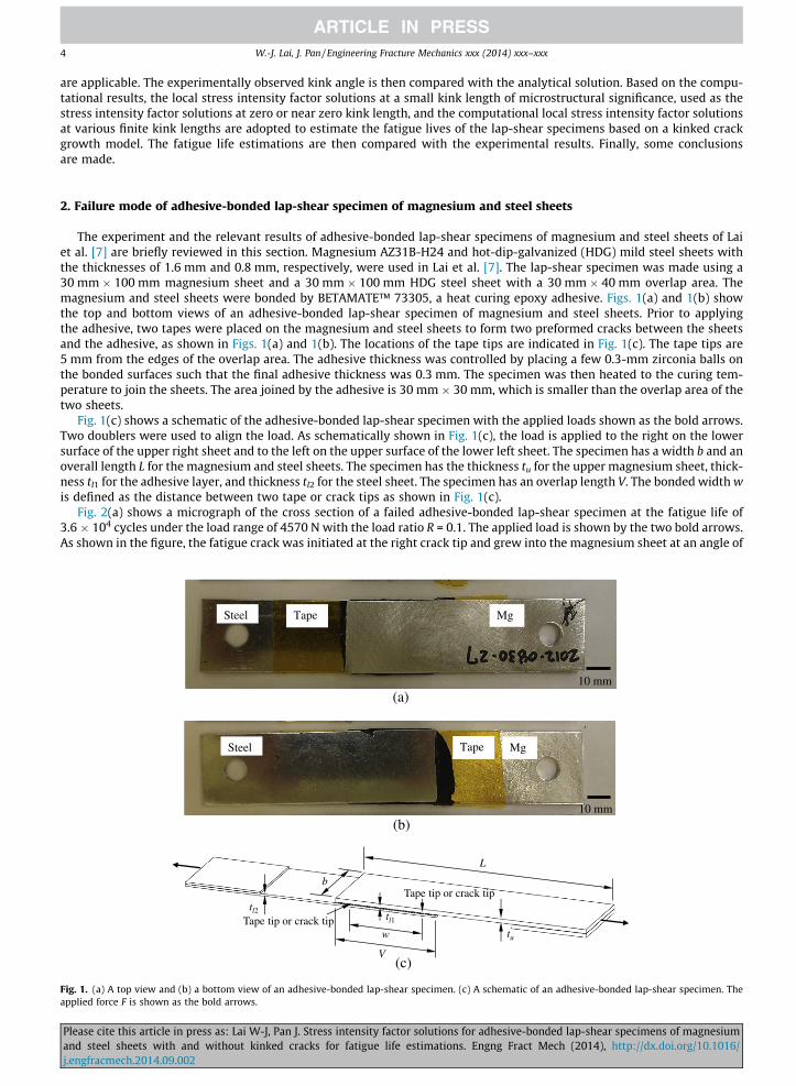
The experiment and the relevant results of adhesive-bonded lap-shear specimens of magnesium and steel sheets of Laiet al. [7] are briefly reviewed in this section. Magnesium AZ31B-H24 and hot-dip-galvanized (HDG) mild steel sheets withthe thicknesses of 1.6 mm and 0.8 mm, respectively, were used in Lai et al. [7]. The lap-shear specimen was made using a30 mm � 100 mm magnesium sheet and a 30 mm � 100 mm HDG steel sheet with a 30 mm � 40 mm overlap area. Themagnesium and steel sheets were bonded by BETAMATE™ 73305, a heat curing epoxy adhesive. Figs. 1(a) and 1(b) showthe top and bottom views of an adhesive-bonded lap-shear specimen of magnesium and steel sheets. Prior to applyingthe adhesive, two tapes were placed on the magnesium and steel sheets to form two preformed cracks between the sheetsand the adhesive, as shown in Figs. 1(a) and 1(b). The locations of the tape tips are indicated in Fig. 1(c). The tape tips are5 mm from the edges of the overlap area. The adhesive thickness was controlled by placing a few 0.3-mm zirconia balls onthe bonded surfaces such that the final adhesive thickness was 0.3 mm. The specimen was then heated to the curing tem-perature to join the sheets. The area joined by the adhesive is 30 mm � 30 mm, which is smaller than the overlap area of thetwo sheets.
Fig. 1(c) shows a schematic of the adhesive-bonded lap-shear specimen with the applied loads shown as the bold arrows.Two doublers were used to align the load. As schematically shown in Fig. 1(c), the load is applied to the right on the lowersurface of the upper right sheet and to the left on the upper surface of the lower left sheet. The specimen has a width b and anoverall length L for the magnesium and steel sheets. The specimen has the thickness tu for the upper magnesium sheet, thick-ness tl1 for the adhesive layer, and thickness tl2 for the steel sheet. The specimen has an overlap length V. The bonded width wis defined as the distance between two tape or crack tips as shown in Fig. 1(c).
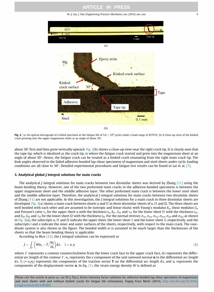
Fig. 2(a) shows a micrograph of the cross section of a failed adhesive-bonded lap-shear specimen at the fatigue life of3.6 � 104 cycles under the load range of 4570 N with the load ratio R = 0.1. The applied load is shown by the two bold arrows.As shown in the figure, the fatigue crack was initiated at the right crack tip and grew into the magnesium sheet at an angle of
(a)
(b)
L
b
V
tu
tl1
tl2
Tape tip or crack tip
Tape tip or crack tipw
(c)
10 mm
10 mm
Steel Mg
Steel Mg
Tape
Tape
Fig. 1. (a) A top view and (b) a bottom view of an adhesive-bonded lap-shear specimen. (c) A schematic of an adhesive-bonded lap-shear specimen. Theapplied force F is shown as the bold arrows.
Please cite this article in press as: Lai W-J, Pan J. Stress intensity factor solutions for adhesive-bonded lap-shear specimens of magnesiumand steel sheets with and without kinked cracks for fatigue life estimations. Engng Fract Mech (2014), http://dx.doi.org/10.1016/j.engfracmech.2014.09.002
AZ31
steel
1 mmTape tip Tape tip
(a)
(b)
Adhesive
Tape tip
Mg
Steel 0.1 mm
30º
Epoxy resin
Kinked crack surface
Kinked crack surface
Tape
Fig. 2. (a) An optical micrograph of a failed specimen at the fatigue life of 3.6 � 104 cycles under a load range of 4570 N. (b) A close-up view of the kinkedcrack growing into the upper magnesium sheet at an angle of about 30�.
W.-J. Lai, J. Pan / Engineering Fracture Mechanics xxx (2014) xxx–xxx 5
about 30� first and then grew vertically upward. Fig. 2(b) shows a close-up view near the right crack tip. It is clearly seen thatthe tape tip, which is idealized as the crack tip, is where the fatigue crack started and grew into the magnesium sheet at anangle of about 30�. Hence, the fatigue crack can be treated as a kinked crack emanating from the right main crack tip. Thekink angles observed in the failed adhesive-bonded lap-shear specimens of magnesium and steel sheets under cyclic loadingconditions are all close to 30�. Detailed experimental procedures and fatigue test results can be found in Lai et al. [7].
3. Analytical global J integral solutions for main cracks
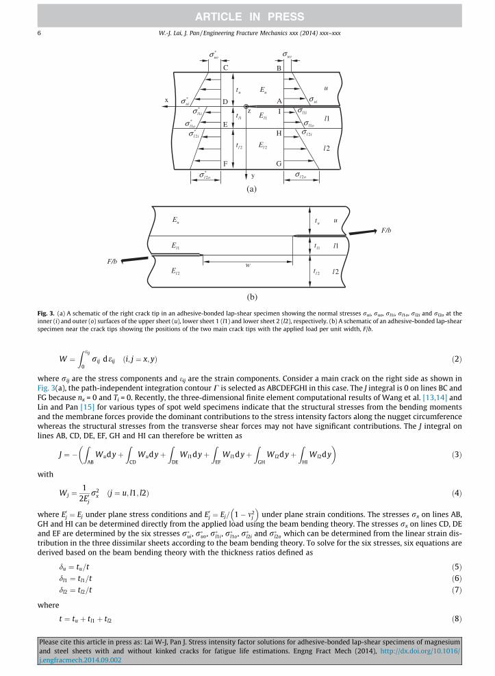
The analytical J integral solutions for main cracks between two dissimilar sheets was derived by Zhang [11] using thebeam bending theory. However, one of the two preformed main cracks in the adhesive-bonded specimens is between theupper magnesium sheet and the middle adhesive layer. The other preformed main crack is between the lower steel sheetand the middle adhesive layer. Therefore, the analytical J integral solutions for main cracks between two dissimilar sheetsof Zhang [11] are not applicable. In this investigation, the J integral solutions for a main crack in three dissimilar sheets aredeveloped. Fig. 3(a) shows a main crack between sheets u and l1 in three dissimilar sheets of u, l1 and l2. The three sheets arewell bonded with each other and are assumed to be isotropic and linear elastic with Young’s modulus Eu, shear modulus Gu
and Poisson’s ratio mu for the upper sheet u with the thickness tu, El1, Gl1 and ml1 for the lower sheet l1 with the thickness tl1,and El2, Gl2 and ml2 for the lower sheet l2 with the thickness tl2. For the normal stresses rui, ruo, rl1i, rl1o, rl2i and rl2o as shownin Fig. 3(a), the subscripts u, l1 and l2 indicate the upper sheet, the lower sheet 1 and the lower sheet 2, respectively, and thesubscripts i and o indicate the inner and outer surfaces of the sheets, respectively, with respect to the main crack. The coor-dinate system is also shown in the figure. The bonded width w is assumed to be much larger than the thicknesses of thesheets so that the beam bending theory is applicable.
According to Rice [12], the J integral solutions can be expressed as
Pleaseand sj.engfr
J ¼Z
CWnx � Ti
@ui
@x
� �ds; i ¼ x; y ð1Þ
where C represents a contour counterclockwise from the lower crack face to the upper crack face, d s represents the differ-ential arc length of the contour C, nx represents the x component of the unit outward normal n to the differential arc lengthds, Ti (= rijnj) represents the components of the traction vector T on the differential arc length ds, and ui represents thecomponents of the displacement vector u. In Eq. (1), the strain energy density W is defined as
cite this article in press as: Lai W-J, Pan J. Stress intensity factor solutions for adhesive-bonded lap-shear specimens of magnesiumteel sheets with and without kinked cracks for fatigue life estimations. Engng Fract Mech (2014), http://dx.doi.org/10.1016/acmech.2014.09.002
(a)
(b)
Fig. 3. (a) A schematic of the right crack tip in an adhesive-bonded lap-shear specimen showing the normal stresses rui, ruo, rl1i, rl1o, rl2i and rl2o at theinner (i) and outer (o) surfaces of the upper sheet (u), lower sheet 1 (l1) and lower sheet 2 (l2), respectively. (b) A schematic of an adhesive-bonded lap-shearspecimen near the crack tips showing the positions of the two main crack tips with the applied load per unit width, F/b.
6 W.-J. Lai, J. Pan / Engineering Fracture Mechanics xxx (2014) xxx–xxx
Pleaseand sj.engfr
W ¼Z eij
0rij deij ði; j ¼ x; yÞ ð2Þ
where rij are the stress components and eij are the strain components. Consider a main crack on the right side as shown inFig. 3(a), the path-independent integration contour C is selected as ABCDEFGHI in this case. The J integral is 0 on lines BC andFG because nx = 0 and Ti = 0. Recently, the three-dimensional finite element computational results of Wang et al. [13,14] andLin and Pan [15] for various types of spot weld specimens indicate that the structural stresses from the bending momentsand the membrane forces provide the dominant contributions to the stress intensity factors along the nugget circumferencewhereas the structural stresses from the transverse shear forces may not have significant contributions. The J integral onlines AB, CD, DE, EF, GH and HI can therefore be written as
J ¼ �Z
ABWudyþ
ZCD
WudyþZ
DEWl1dyþ
ZEF
Wl1dyþZ
GHWl2dyþ
ZHI
Wl2dy� �
ð3Þ
with
Wj ¼1
2E0jr2
x ðj ¼ u; l1; l2Þ ð4Þ
where E0j ¼ Ej under plane stress conditions and E0j ¼ Ej= 1� m2j
� �under plane strain conditions. The stresses rx on lines AB,
GH and HI can be determined directly from the applied load using the beam bending theory. The stresses rx on lines CD, DEand EF are determined by the six stresses r�ui, r�uo, r�l1i, r�l1o, r�l2i and r�l2o which can be determined from the linear strain dis-tribution in the three dissimilar sheets according to the beam bending theory. To solve for the six stresses, six equations arederived based on the beam bending theory with the thickness ratios defined as
du ¼ tu=t ð5Þdl1 ¼ tl1=t ð6Þdl2 ¼ tl2=t ð7Þ
where
t ¼ tu þ tl1 þ tl2 ð8Þ
cite this article in press as: Lai W-J, Pan J. Stress intensity factor solutions for adhesive-bonded lap-shear specimens of magnesiumteel sheets with and without kinked cracks for fatigue life estimations. Engng Fract Mech (2014), http://dx.doi.org/10.1016/acmech.2014.09.002
Main crack
Adhesive
Steel
Crack tip
Mg
(b)
Main crackAdhesive
Steel Crack tip
Mg
(c)
w
V
ut1lt2lt
L
F/b
dθ
x
y
(a)
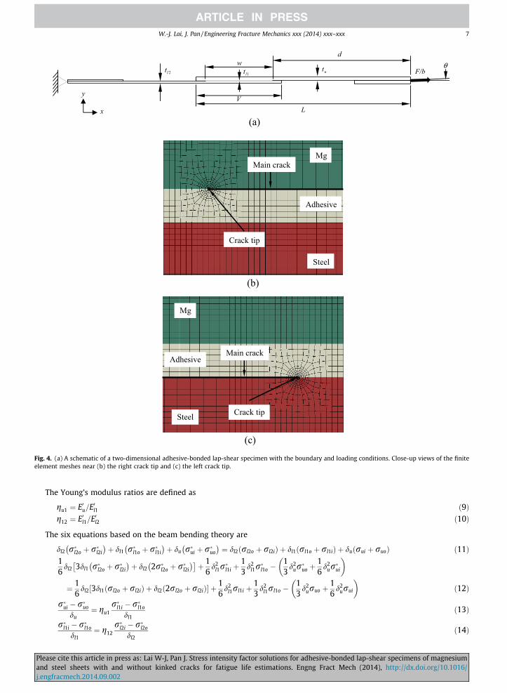
Fig. 4. (a) A schematic of a two-dimensional adhesive-bonded lap-shear specimen with the boundary and loading conditions. Close-up views of the finiteelement meshes near (b) the right crack tip and (c) the left crack tip.
W.-J. Lai, J. Pan / Engineering Fracture Mechanics xxx (2014) xxx–xxx 7
The Young’s modulus ratios are defined as
Pleaseand sj.engfr
gu1 ¼ E0u=E0l1 ð9Þg12 ¼ E0l1=E0l2 ð10Þ
The six equations based on the beam bending theory are
dl2 r�l2o þ r�l2i
� �þ dl1 r�l1o þ r�l1i
� �þ du r�ui þ r�uo
� �¼ dl2 rl2o þ rl2ið Þ þ dl1 rl1o þ rl1ið Þ þ duðrui þ ruoÞ ð11Þ
16
dl2 3dl1 r�l2o þ r�l2i
� �þ dl2 2r�l2o þ r�l2i
� �� þ 1
6d2
l1r�l1i þ
13
d2l1r�l1o �
13
d2ur�uo þ
16
d2ur�ui
� �
¼ 16
dl2 3dl1 rl2o þ rl2ið Þ þ dl2 2rl2o þ rl2ið Þ½ � þ 16
d2l1rl1i þ
13
d2l1rl1o �
13
d2uruo þ
16
d2urui
� �ð12Þ
r�ui � r�uo
du¼ gu1
r�l1i � r�l1o
dl1ð13Þ
r�l1i � r�l1o
dl1¼ g12
r�l2i � r�l2o
dl2ð14Þ
cite this article in press as: Lai W-J, Pan J. Stress intensity factor solutions for adhesive-bonded lap-shear specimens of magnesiumteel sheets with and without kinked cracks for fatigue life estimations. Engng Fract Mech (2014), http://dx.doi.org/10.1016/acmech.2014.09.002

8 W.-J. Lai, J. Pan / Engineering Fracture Mechanics xxx (2014) xxx–xxx
Pleaseand sj.engfr
r�ui ¼ gu1r�l1i ð15Þr�l1o ¼ g12r
�l2i ð16Þ
Eqs. (11) and (12) are from the force and moment equilibrium conditions, respectively. Eqs. (13) and (14) are from the linearstrain distribution in the three dissimilar sheets. Eqs. (15) and (16) are from the strain continuity conditions at the two inter-faces. Solving Eqs. (11)–(16) gives the six normal structural stresses r�ui, r�uo, r�l1i, r�l1o, r�l2i and r�l2o. Substituting the six normalstructural stresses r�ui, r�uo, r�l1i, r�l1o, r�l2i and r�l2o into Eq. (4) and integrating over the contour C, the J integral solutions for themain crack in three dissimilar sheets can be expressed as
J ¼ t6E0uD
N1r2ui þ N2r2
uo þ N3r2l1i þ N4r2
l1o þ N5r2l2i þ N6r2
l2o þ N7ruiruo þ N8ruirl1i þ N9ruirl1o þ N10ruirl2i�
þ N11ruirl2o þ N12ruorl1i þ N13ruorl1o þ N14ruorl2i þ N15ruorl2o þ N16rl1irl1o þ N17rl1irl2i þ N18rl1irl2o
þ N19rl1orl2i þ N20rl1orl2o þ N21rl2irl2oÞ ð17Þ
where
N1 ¼ C04100 þ 4C31110 þ 6C22110 þ 4C13110 þ C40120 þ 3C21211 þ 3C12211 þ C03211 þ 6C11311 þ 3C02311 þ 3C01411
þ C30221 þ 3C20321 þ 3C10421 ð18ÞN2 ¼ C04100 þ 4C31110 þ 6C22110 þ 4C13110 þ C40120 þ 3C21211 þ 3C12211 þ C03211 þ C30221 ð19ÞN3 ¼ C14012 þ C23011 þ 12C31112 þ 12C22112 þ 4C13112 þ 12C21212 þ 6C12212 þ 4C11312 þ 3C40122 þ 3C30222
þ C20322 þ C10423 ð20ÞN4 ¼ C14001 þ 3C41011 þ 3C32011 þ C23011 þ 12C31112 þ 12C22112 þ 4C13112 þ 12C21212 þ 6C12212 þ 4C11312
þ C20322 þ C10423 ð21ÞN5 ¼ C32021 þ 3C23021 þ 3C14021 þ C41031 þ 3C22122 þ 6C13122 þ 3C04122 þ 3C12222 þ 3C03222 þ C02322 þ 4C31132
þ 6C21232 þ 4C11332 þ C01433 ð22ÞN6 ¼ C32021 þ C41031 þ 3C22122 þ 3C12222 þ C02322 þ 4C31132 þ 6C21232 þ 4C11332 þ C01433 ð23ÞN7 ¼ C04100 þ 4C31110 þ 6C22110 þ 4C13110 þ C40120 � 6C21211 � 6C12211 � 2C03211 � 6C11311 � 3C02311
� 2C30221 � 3C20321 ð24ÞN8 ¼ �12C31111 � 15C22111 � 6C13111 � 4C21211 � 3C12211 � 3C40121 � C30221 � C20322 � 3C10422 ð25ÞN9 ¼ �6C31111 � 12C22111 � 6C13111 � 2C21211 � 3C12211 þ C30221 � 2C20322 � 3C10422 ð26ÞN10 ¼ �3C13111 � 3C04111 � C03211 þ 3C31121 þ 3C22121 þ 3C21221 þ 2C12221 � 3C11322 � C02322 � 3C01422 ð27ÞN11 ¼ 3C13111 þ C03211 þ 3C31121 þ 6C22121 þ 3C21221 þ 4C12221 � 3C11322 � 2C02322 þ 3C01422 ð28ÞN12 ¼ �12C31111 � 15C22111 � 6C13111 � 8C21211 � 6C12211 � 3C40121 � 2C30221 þ C20322 ð29ÞN13 ¼ �6C31111 � 12C22111 � 6C13111 � 4C21211 � 6C12211 þ 2C30221 þ 2C20322 ð30ÞN14 ¼ �3C13111 � 3C04111 � 2C03211 þ 3C31121 þ 3C22121 þ 6C21221 þ 4C12221 þ 3C11322 þ C02322 ð31ÞN15 ¼ 3C13111 þ 2C03211 þ 3C31121 þ 6C22121 þ 6C21221 þ 8C12221 þ 3C11322 þ 2C02322 ð32ÞN16 ¼ C14001 � 3C32011 � 2C23011 þ 12C31112 þ 12C22112 þ 4C13112 þ 12C21212 þ 6C12212 þ 4C11312
� 3C30222 � 2C20322 þ C10423 ð33ÞN17 ¼ �2C23011 � 3C14011 þ C32021 � 6C31122 � 2C22122 � 12C21222 � 3C12222 � 6C11322 ð34ÞN18 ¼ 2C23011 þ 2C32021 � 6C31122 � 4C22122 � 12C21222 � 6C12222 � 6C11322 ð35ÞN19 ¼ �C23011 � 3C14011 � 3C41021 � C32021 � 12C31122 � 4C22122 � 15C21222 � 3C12222 � 6C11322 ð36ÞN20 ¼ C23011 � 3C41021 � 2C32021 � 12C31122 � 8C22122 � 15C21222 � 6C12222 � 6C11322 ð37ÞN21 ¼ �2C32021 � 3C23021 þ C41031 � 6C22122 � 6C13122 � 6C12222 � 3C03222 � 2C02322 þ 4C31132 þ 6C21232
þ 4C11332 þ C01433 ð38ÞD ¼ C04000 þ 4C31010 þ 6C22010 þ 4C13010 þ C40020 þ 12C21111 þ 12C12111 þ 4C03111 þ 12C11211 þ 6C02211
þ 4C01311 þ 4C30121 þ 6C20221 þ 4C10321 þ C00422 ð39Þ
with
Cijklm ¼ dil1d
jl2d
kug
l12g
mu1 ð40Þ
Fig. 3(b) shows a schematic of the lap-shear specimen near the crack tips. Fig. 4(a) shows a schematic of the lap-shearspecimen with the applied load F/b. The positions of the two main crack tips are also shown in Figs. 3(b) and 4(a). Forthe loading conditions shown in Figs. 3(b) and 4(a), the normal structural stresses rui, ruo, rl1i, rl1o, rl2i and rl2o for the rightcrack tip are
cite this article in press as: Lai W-J, Pan J. Stress intensity factor solutions for adhesive-bonded lap-shear specimens of magnesiumteel sheets with and without kinked cracks for fatigue life estimations. Engng Fract Mech (2014), http://dx.doi.org/10.1016/acmech.2014.09.002
W.-J. Lai, J. Pan / Engineering Fracture Mechanics xxx (2014) xxx–xxx 9
Pleaseand sj.engfr
rui;right ¼4F cos h
btuþ 6Fd sin h
bt2u
ð41Þ
ruo;right ¼ �2F cos h
btu� 6Fd sin h
bt2u
ð42Þ
rl1i;right ¼ 0 ð43Þrl1o;right ¼ 0 ð44Þrl2i;right ¼ 0 ð45Þrl2o;right ¼ 0 ð46Þ
where h is the angle between the loading direction and the x direction, d is the distance from the load application point to thenearest main crack tip, and F/b is the applied load per unit width as shown in Fig. 4(a). The first and second terms in Eqs. (41)and (42) are due to the decomposed forces, F cos h and F sin h, in the horizontal and vertical directions, respectively. Substi-tuting Eqs. (41)–(46) into Eq. (17) gives the value of the J integral for the right crack tip.
The asymptotic in-plane stress field around a main crack tip is an oscillatory field that can be characterized by a complexstress intensity factor K ¼ K1 þ iK2; i ¼
ffiffiffiffiffiffiffi�1p� �
[16,17]. The stresses ry and sxy at a small distance r ahead of a main crack tipare characterized by K as
ry þ isxy ¼K1 þ iK2ffiffiffiffiffiffiffiffiffi
2prp r
tc
� �ie
ð47Þ
For the right crack as shown in Fig. 3(b), the bimaterial constant e is defined as
e ¼ 12p
lnju=Gu þ 1=Gl1
jl1=Gl1 þ 1=Guð48Þ
where
ju ¼ 3� 4mu ð49Þ
and
jl1 ¼ 3� 4ml1 ð50Þ
under plane strain conditions. For the left crack as shown in Fig. 3(b), the bimaterial constant e is defined as
e ¼ 12p
lnjl2=Gl2 þ 1=Gl1
jl1=Gl1 þ 1=Gl2ð51Þ
where
jl2 ¼ 3� 4ml2 ð52Þ
under plane strain conditions. In Eq. (47), tc represents a characteristic length [11,17]. It should be noted that when the twomaterials are identical, e = 0. In this case, K1 and K2 in Eq. (47) for the main crack become the conventional stress intensityfactors KI and KII, respectively.
The J integral solutions is directly related to the effective stress intensity factor Ke for both the right and left cracks definedas
Ke ¼ffiffiffiffiffiffiffiffiffiffiffiffiffiffiffiffiffiK2
1 þ K22
q¼
ffiffiffiffiffiffiffiffiffiffiffiffiffiffiffiffiffiffiffiffiffiffiffiffiffiffiffiffiffiJ cosh2ðpeÞE�
qð53Þ
where
1E�¼ 1
21E0uþ 1
E0l1
� �ð54Þ
for the right crack and
1E�¼ 1
21
E0l1þ 1
E0l2
� �ð55Þ
for the left crack.
4. Computational global stress intensity factor solutions for main cracks
Fig. 4(a) shows a schematic of a two-dimensional finite element model of a lap-shear specimen with the boundary andloading conditions. The specimen has the upper sheet thickness tu, the lower sheet 1 thickness tl1, and the lower sheet 2thickness tl2, the length L, the overlap length V, and the bonded width w. The x–y coordinate system is shown in the figure.
cite this article in press as: Lai W-J, Pan J. Stress intensity factor solutions for adhesive-bonded lap-shear specimens of magnesiumteel sheets with and without kinked cracks for fatigue life estimations. Engng Fract Mech (2014), http://dx.doi.org/10.1016/acmech.2014.09.002
10 W.-J. Lai, J. Pan / Engineering Fracture Mechanics xxx (2014) xxx–xxx
The left edge is fixed at the middle surface while the right edge has a concentrated force per unit width, F/b, applied at themiddle surface.
The two-dimensional plane strain finite element model has tu = 1.6 mm, tl1 = 0.3 mm, tl2 = 0.8 mm, L = 100 mm andV = 40 mm. The specimen width b is 30 mm, the angle h between the loading direction and the x direction is 0.107�, andthe distance d from the load application point to the nearest main crack tip is 65 mm based on the specimen geometryand the test setup in Lai et al. [7]. Note that the ratio of the bonded width w to the upper sheet thickness tu is 37.5 forthe specimens used in the experiments. The two-dimensional plane strain finite element model is used to obtain the globalstress intensity factor solutions for calculating the local stress intensity factor solutions for kinked cracks. Figs. 4(b) and (c)show the closed-up views of the meshes near the right and left main crack tips, respectively. All the materials are assumed tobe isotropic and linear elastic. The top AZ31-H24 sheet is modeled with the Young’s modulus Eu = 45 GPa and the Poisson’sratio mu = 0.35. The middle adhesive layer is modeled with the Young’s modulus El1 = 4.1 GPa and the Poisson’s ratioml1 = 0.36. The bottom steel sheet is modeled with the Young’s modulus El2 = 207 GPa and the Poisson’s ratio ml2 = 0.3.Second-order, isoparametric, quadrilateral, reduced integration, plane strain elements (CPE8R) were used in the model.The crack-tip elements were modified with collapsed nodes at the crack tip and the midside nodes on the sides were movedto the quarter points from the crack tip to model the 1=
ffiffiffirp
singularity near the crack tip. The commercial finite elementprogram ABAQUS [18] was employed to perform the computation.
It should be noted that the KA1 and KA
2 of the complex stress intensity factor KA ¼ KA1 þ iKA
2
� �obtained directly from
ABAQUS [18] are defined such that the stresses ry and sxy at a small distance r ahead of a main crack tip are characterizedby KA as
Pleaseand sj.engfr
ry þ isxy ¼KA
1 þ iKA2ffiffiffiffiffiffiffiffiffi
2prp rie ð56Þ
By comparing Eqs. (47) and (56), the K1 and K2 solutions can be related to the KA1 and KA
2 solutions as
K1 ¼ KA1 cosðe ln tcÞ � KA
2 sinðe ln tcÞ ð57ÞK2 ¼ KA
1 sinðe ln tcÞ þ KA2 cosðe ln tcÞ ð58Þ
Here, the characteristic length tc is taken as the upper magnesium sheet thickness tu (=1.6 mm) for calculating the K1 and K2
solutions. It is noted that the global effective stress intensity factor Ke ¼ffiffiffiffiffiffiffiffiffiffiffiffiffiffiffiffiffiK2
1 þ K22
q¼
ffiffiffiffiffiffiffiffiffiffiffiffiffiffiffiffiffiffiffiffiffiffiffiffiffiffiffiffiffiffiffiffiffiKA
1
� �2þ KA
2
� �2r !
is independent of
the selection of a characteristic length tc. In this investigation, the computational K1 and K2 solutions for the interface cracksare obtained from Eqs. (57) and (58) with the KA
1 and KA2 solutions obtained from ABAQUS [18].
The computational results can be expressed in the normalized forms as
K1 ¼ F1ðdu; dl1; dl2;gu1;g12Þ �F
bffiffiffiffitup ð59Þ
K2 ¼ F2ðdu; dl1; dl2;gu1;g12Þ �F
bffiffiffiffitup ð60Þ
Ke ¼ Feðdu; dl1; dl2;gu1;g12Þ �F
bffiffiffiffitup ð61Þ
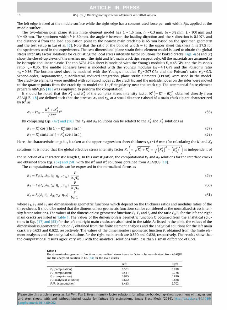
where F1, F2 and Fe are dimensionless geometric functions which depend on the thickness ratios and modulus ratios of thethree sheets. It should be noted that the dimensionless geometric functions can be considered as the normalized stress inten-sity factor solutions. The values of the dimensionless geometric functions F1, F2 and Fe and the ratio F2/F1 for the left and rightmain cracks are listed in Table 1. The values of the dimensionless geometric function Fe obtained from the analytical solu-tions in Eqs. (17) and (53) for the left and right main cracks are also listed in the table. As listed in the table, the values of thedimensionless geometric function Fe obtained from the finite element analyses and the analytical solutions for the left maincrack are 0.625 and 0.622, respectively. The values of the dimensionless geometric function Fe obtained from the finite ele-ment analyses and the analytical solutions for the right main crack are 0.830 and 0.828, respectively. The results show thatthe computational results agree very well with the analytical solutions with less than a small difference of 0.5%.
Table 1The dimensionless geometric functions or normalized stress intensity factor solutions obtained from ABAQUSand the analytical solution in Eq. (53) for the main cracks.
Left Right
F1 (computation) 0.361 0.288F2 (computation) 0.511 0.778Fe (computation) 0.625 0.830Fe (analytical solution) 0.622 0.828F2/F1 (computation) 1.413 2.702
cite this article in press as: Lai W-J, Pan J. Stress intensity factor solutions for adhesive-bonded lap-shear specimens of magnesiumteel sheets with and without kinked cracks for fatigue life estimations. Engng Fract Mech (2014), http://dx.doi.org/10.1016/acmech.2014.09.002
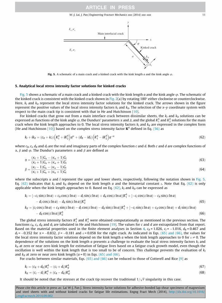
Fig. 5. A schematic of a main crack and a kinked crack with the kink length a and the kink angle u.
W.-J. Lai, J. Pan / Engineering Fracture Mechanics xxx (2014) xxx–xxx 11
5. Analytical local stress intensity factor solutions for kinked cracks
Fig. 5 shows a schematic of a main crack and a kinked crack with the kink length a and the kink angle u. The schematic ofthe kinked crack is consistent with the kinked crack shown in Fig. 2(a) by rotating 180� either clockwise or counterclockwise.Here, kI and kII represent the local stress intensity factor solutions for the kinked crack. The arrows shown in the figurerepresent the positive values of the local stress intensity factors kI and kII. The selection of the x–y coordinate system withrespect to the main crack tip is consistent with that in He and Hutchinson [10].
For kinked cracks that grow out from a main interface crack between dissimilar sheets, the kI and kII solutions can beexpressed as functions of the kink angle u, the Dundurs’ parameters a and b, and the global KA
1 and KA2 solutions for the main
crack when the kink length approaches to 0. The local stress intensity factors kI and kII are expressed in the complex form(He and Hutchinson [10]) based on the complex stress intensity factor KA defined in Eq. (56) as
Pleaseand sj.engfr
kI þ ikII ¼ ðcR þ icIÞ KA1 þ iKA
2
� �aie þ ðdR � idIÞ KA
1 � iKA2
� �a�ie ð62Þ
where cR, cI, dR and dI are the real and imaginary parts of the complex function c and d. Both c and d are complex functions ofa, b and u. The Dundur’s parameters a and b are defined as
a ¼ ðjl þ 1ÞGu � ðju þ 1ÞGl
ðjl þ 1ÞGu þ ðju þ 1ÞGlð63Þ
b ¼ ðjl � 1ÞGu � ðju � 1ÞGl
ðjl þ 1ÞGu þ ðju þ 1ÞGlð64Þ
where the subscripts u and l represent the upper and lower sheets, respectively, following the notation shown in Fig. 5.Eq. (62) indicates that kI and kII depend on the kink length a and the bimaterial constant e. Note that Eq. (62) is onlyapplicable when the kink length approaches to 0. Based on Eq. (62), kI and kII can be expressed as
kI ¼ ½�cI sinðe ln aÞ þ cR cosðe ln aÞ � dI sinðe ln aÞ þ dR cosðe ln aÞ�KA1 þ �cI cosðe ln aÞ � cR sinðe ln aÞ½
� dI cosðe ln aÞ � dR sinðe ln aÞ�KA2 ð65Þ
kII ¼ ½cI cosðe ln aÞ þ cR sinðe ln aÞ � dI cosðe ln aÞ � dR sinðe ln aÞ�KA1 þ �cI sinðe ln aÞ þ cR cosðe ln aÞ þ dI sinðe ln aÞ½
� dR cosðe ln aÞ�KA2 ð66Þ
The global stress intensity factors KA1 and KA
2 were obtained computationally as mentioned in the previous section. Thefunctions cR, cI, dR and dI are tabulated in He and Hutchinson [19]. The values for c and d are extrapolated from that report.Based on the material properties used in the finite element analyses in Section 4, cR = 1.026, cI = �1.016, dR = 0.467 anddI = �0.352 for a = �0.832, b = �0.181 and e = 0.058 for the right crack. As indicated in Eqs. (65) and (66), the values forthe local stress intensity factor solutions depend on the kink length a when the kink length approaches to 0 for e – 0. Thedependence of the solutions on the kink length a presents a challenge to evaluate the local stress intensity factors kI andkII at zero or near zero kink length for estimation of fatigue lives based on a fatigue crack growth model, even though theoscillation is well within the kink length that is too small to be of concern. This challenge prevents the evaluation of kI
and kII at zero or near zero kink length (a = 0) in Eqs. (65) and (66).For cracks between similar materials, Eqs. (65) and (66) can be reduced to those of Cotterell and Rice [9] as
kI ¼ ðcR þ dRÞKAI � ðcI þ dIÞKA
II ð67ÞkII ¼ ðcI � dIÞKA
I þ ðcR � dRÞKAII ð68Þ
It should be noted that the stresses at the crack tip recover the traditional 1=ffiffiffirp
singularity in this case.
cite this article in press as: Lai W-J, Pan J. Stress intensity factor solutions for adhesive-bonded lap-shear specimens of magnesiumteel sheets with and without kinked cracks for fatigue life estimations. Engng Fract Mech (2014), http://dx.doi.org/10.1016/acmech.2014.09.002
12 W.-J. Lai, J. Pan / Engineering Fracture Mechanics xxx (2014) xxx–xxx
The local stress intensity factor solutions kI and kII for kinked cracks with finite kink lengths in lap-shear specimens can beexpressed in the normalized forms based on the beam bending theory as
Fig. 6.loading
Pleaseand sj.engfr
kIatu
� �¼ f I
atu
� �� Fbffiffiffiffitup ð69Þ
kIIatu
� �¼ f II
atu
� �� Fbffiffitp
uð70Þ
and the local effective stress intensity factor solution ke can be expressed as
keatu
� �¼
ffiffiffiffiffiffiffiffiffiffiffiffiffiffiffiffiffiffiffiffiffiffiffiffiffiffiffiffiffiffiffiffiffiffiffiffiffiffik2
Iatu
� �þ k2
IIatu
� �s¼ f e
atu
� �� Fbffiffiffiffitup ð71Þ
where fI, fII and fe are dimensionless geometric functions which depend on the normalized kink length a/tu for this particularset of the geometry and material combination in the lap-shear specimen. The analytical local stress intensity factor kI and kII
solutions for the kinked cracks in the lap-shear specimens can be obtained using Eqs. (65) and (66) with the values of K1 andK2 obtained from the finite element analyses. The results will be presented in the normalized form in the following section.
6. Computational local stress intensity factor solutions for kinked cracks
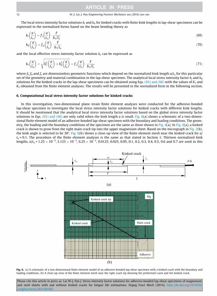
In this investigation, two-dimensional plane strain finite element analyses were conducted for the adhesive-bondedlap-shear specimen to investigate the local stress intensity factor solutions for kinked cracks with different kink lengths.It should be mentioned that the analytical local stress intensity factor solutions based on the global stress intensity factorsolutions in Eqs. (65) and (66) are only valid when the kink length a is small. Fig. 6(a) shows a schematic of a two-dimen-sional finite element model of an adhesive-bonded lap-shear specimen with the boundary and loading conditions. The geom-etry, the loading and the boundary conditions of the specimen are the same as those shown in Fig. 4(a). In Fig. 6(a), a kinkedcrack is shown to grow from the right main crack tip into the upper magnesium sheet. Based on the micrograph in Fig. 2(b),the kink angle is selected to be 30�. Fig. 6(b) shows a close-up view of the finite element mesh near the kinked crack for a/tu = 0.1. The procedure of the finite element analyses is the same as that stated in Section 4. Thirteen normalized kinklengths, a/tu = 1.25 � 10�5, 3.125 � 10�3, 6.25 � 10�3, 0.0125, 0.025, 0.05, 0.1, 0.2, 0.3, 0.4, 0.5, 0.6 and 0.7 are used in this
w
V
ut1lt2lt
L
F/b
Kinked crack
x
y
(a)
Kinked crack tip
Kinked crack Main crack
Mg
Adhesive
(b)
(a) A schematic of a two-dimensional finite element model of an adhesive-bonded lap-shear specimen with a kinked crack with the boundary andconditions. (b) A close-up view of the finite element mesh near the right crack tip showing the preformed crack and the kinked crack.
cite this article in press as: Lai W-J, Pan J. Stress intensity factor solutions for adhesive-bonded lap-shear specimens of magnesiumteel sheets with and without kinked cracks for fatigue life estimations. Engng Fract Mech (2014), http://dx.doi.org/10.1016/acmech.2014.09.002
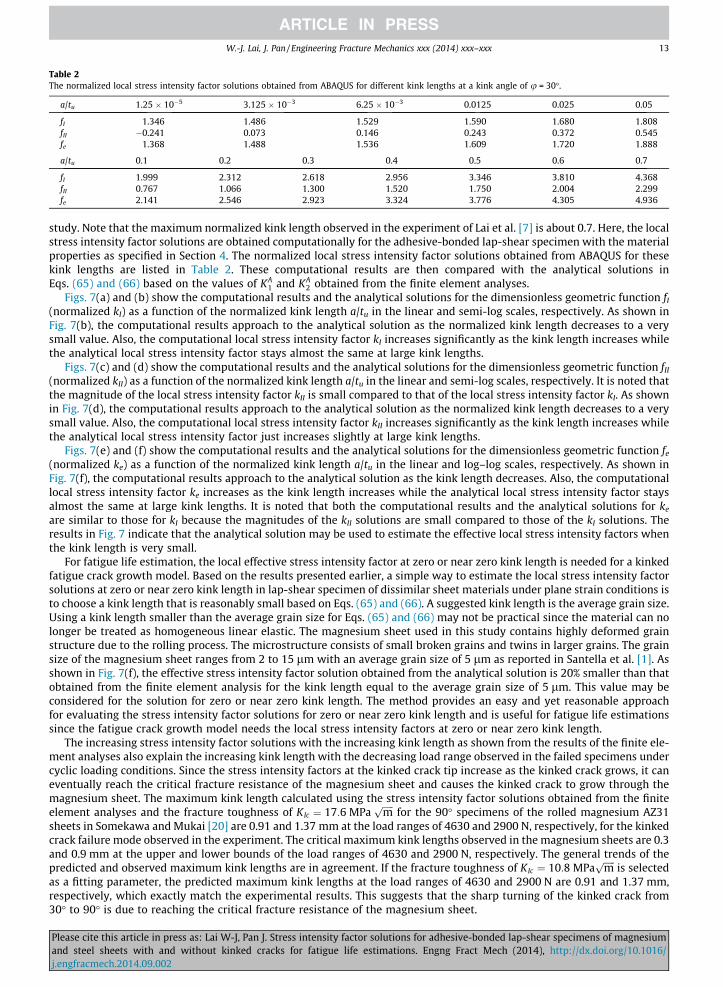
Table 2The normalized local stress intensity factor solutions obtained from ABAQUS for different kink lengths at a kink angle of u = 30�.
a/tu 1.25 � 10�5 3.125 � 10�3 6.25 � 10�3 0.0125 0.025 0.05
fI 1.346 1.486 1.529 1.590 1.680 1.808fII �0.241 0.073 0.146 0.243 0.372 0.545fe 1.368 1.488 1.536 1.609 1.720 1.888
a/tu 0.1 0.2 0.3 0.4 0.5 0.6 0.7
fI 1.999 2.312 2.618 2.956 3.346 3.810 4.368fII 0.767 1.066 1.300 1.520 1.750 2.004 2.299fe 2.141 2.546 2.923 3.324 3.776 4.305 4.936
W.-J. Lai, J. Pan / Engineering Fracture Mechanics xxx (2014) xxx–xxx 13
study. Note that the maximum normalized kink length observed in the experiment of Lai et al. [7] is about 0.7. Here, the localstress intensity factor solutions are obtained computationally for the adhesive-bonded lap-shear specimen with the materialproperties as specified in Section 4. The normalized local stress intensity factor solutions obtained from ABAQUS for thesekink lengths are listed in Table 2. These computational results are then compared with the analytical solutions inEqs. (65) and (66) based on the values of KA
1 and KA2 obtained from the finite element analyses.
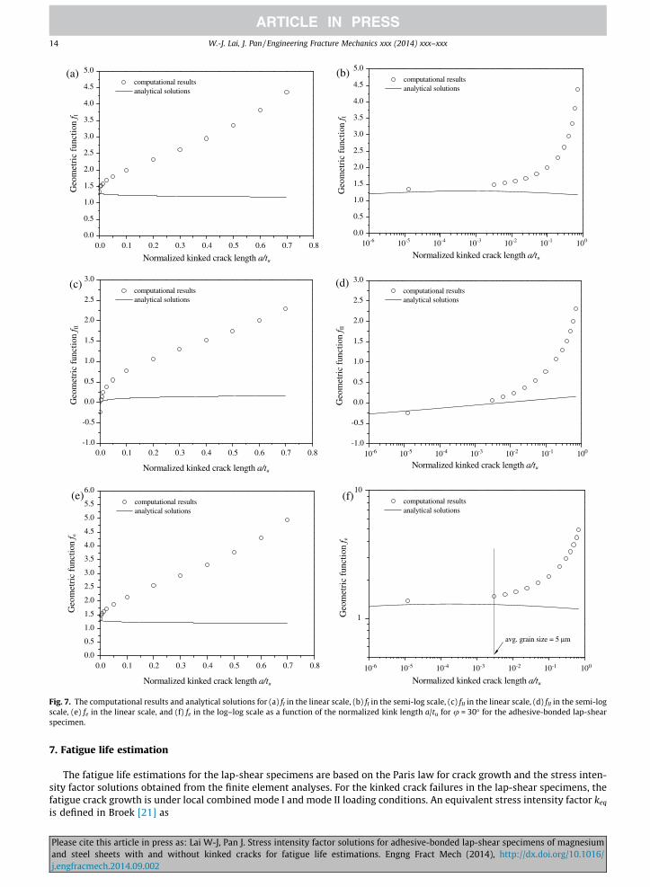
Figs. 7(a) and (b) show the computational results and the analytical solutions for the dimensionless geometric function fI
(normalized kI) as a function of the normalized kink length a/tu in the linear and semi-log scales, respectively. As shown inFig. 7(b), the computational results approach to the analytical solution as the normalized kink length decreases to a verysmall value. Also, the computational local stress intensity factor kI increases significantly as the kink length increases whilethe analytical local stress intensity factor stays almost the same at large kink lengths.
Figs. 7(c) and (d) show the computational results and the analytical solutions for the dimensionless geometric function fII
(normalized kII) as a function of the normalized kink length a/tu in the linear and semi-log scales, respectively. It is noted thatthe magnitude of the local stress intensity factor kII is small compared to that of the local stress intensity factor kI. As shownin Fig. 7(d), the computational results approach to the analytical solution as the normalized kink length decreases to a verysmall value. Also, the computational local stress intensity factor kII increases significantly as the kink length increases whilethe analytical local stress intensity factor just increases slightly at large kink lengths.
Figs. 7(e) and (f) show the computational results and the analytical solutions for the dimensionless geometric function fe
(normalized ke) as a function of the normalized kink length a/tu in the linear and log–log scales, respectively. As shown inFig. 7(f), the computational results approach to the analytical solution as the kink length decreases. Also, the computationallocal stress intensity factor ke increases as the kink length increases while the analytical local stress intensity factor staysalmost the same at large kink lengths. It is noted that both the computational results and the analytical solutions for ke
are similar to those for kI because the magnitudes of the kII solutions are small compared to those of the kI solutions. Theresults in Fig. 7 indicate that the analytical solution may be used to estimate the effective local stress intensity factors whenthe kink length is very small.
For fatigue life estimation, the local effective stress intensity factor at zero or near zero kink length is needed for a kinkedfatigue crack growth model. Based on the results presented earlier, a simple way to estimate the local stress intensity factorsolutions at zero or near zero kink length in lap-shear specimen of dissimilar sheet materials under plane strain conditions isto choose a kink length that is reasonably small based on Eqs. (65) and (66). A suggested kink length is the average grain size.Using a kink length smaller than the average grain size for Eqs. (65) and (66) may not be practical since the material can nolonger be treated as homogeneous linear elastic. The magnesium sheet used in this study contains highly deformed grainstructure due to the rolling process. The microstructure consists of small broken grains and twins in larger grains. The grainsize of the magnesium sheet ranges from 2 to 15 lm with an average grain size of 5 lm as reported in Santella et al. [1]. Asshown in Fig. 7(f), the effective stress intensity factor solution obtained from the analytical solution is 20% smaller than thatobtained from the finite element analysis for the kink length equal to the average grain size of 5 lm. This value may beconsidered for the solution for zero or near zero kink length. The method provides an easy and yet reasonable approachfor evaluating the stress intensity factor solutions for zero or near zero kink length and is useful for fatigue life estimationssince the fatigue crack growth model needs the local stress intensity factors at zero or near zero kink length.
The increasing stress intensity factor solutions with the increasing kink length as shown from the results of the finite ele-ment analyses also explain the increasing kink length with the decreasing load range observed in the failed specimens undercyclic loading conditions. Since the stress intensity factors at the kinked crack tip increase as the kinked crack grows, it caneventually reach the critical fracture resistance of the magnesium sheet and causes the kinked crack to grow through themagnesium sheet. The maximum kink length calculated using the stress intensity factor solutions obtained from the finiteelement analyses and the fracture toughness of KIc ¼ 17:6 MPa
ffiffiffiffiffimp
for the 90� specimens of the rolled magnesium AZ31sheets in Somekawa and Mukai [20] are 0.91 and 1.37 mm at the load ranges of 4630 and 2900 N, respectively, for the kinkedcrack failure mode observed in the experiment. The critical maximum kink lengths observed in the magnesium sheets are 0.3and 0.9 mm at the upper and lower bounds of the load ranges of 4630 and 2900 N, respectively. The general trends of thepredicted and observed maximum kink lengths are in agreement. If the fracture toughness of KIc ¼ 10:8 MPa
ffiffiffiffiffimp
is selectedas a fitting parameter, the predicted maximum kink lengths at the load ranges of 4630 and 2900 N are 0.91 and 1.37 mm,respectively, which exactly match the experimental results. This suggests that the sharp turning of the kinked crack from30� to 90� is due to reaching the critical fracture resistance of the magnesium sheet.
Please cite this article in press as: Lai W-J, Pan J. Stress intensity factor solutions for adhesive-bonded lap-shear specimens of magnesiumand steel sheets with and without kinked cracks for fatigue life estimations. Engng Fract Mech (2014), http://dx.doi.org/10.1016/j.engfracmech.2014.09.002
0.0
0.5
1.0
1.5
2.0
2.5
3.0
3.5
4.0
4.5
5.0
computational results analytical solutions
Geo
met
ric
func
tion
f I
Normalized kinked crack length a/tu
(a)
10-6 10-5 10-4 10-3 10-2 10-1 1000.0
0.5
1.0
1.5
2.0
2.5
3.0
3.5
4.0
4.5
5.0
computational results analytical solutions
Geo
met
ric
func
tion
f I
Normalized kinked crack length a/tu
(b)
-1.0
-0.5
0.0
0.5
1.0
1.5
2.0
2.5
3.0
computational results analytical solutions
Geo
met
ric
func
tion
f II
Normalized kinked crack length a/tu
(c)
10-6 10-5 10-4 10-3 10-2 10-1 100-1.0
-0.5
0.0
0.5
1.0
1.5
2.0
2.5
3.0 computational results analytical solutions
Geo
met
ric
func
tion
f II
Normalized kinked crack length a/tu
(d)
0.0 0.1 0.2 0.3 0.4 0.5 0.6 0.7 0.8
0.0 0.1 0.2 0.3 0.4 0.5 0.6 0.7 0.8
0.0 0.1 0.2 0.3 0.4 0.5 0.6 0.7 0.80.0
0.5
1.0
1.5
2.0
2.5
3.0
3.5
4.0
4.5
5.0
5.5
6.0
computational results analytical solutions
Geo
met
ric
func
tion
f e
Normalized kinked crack length a/tu
(e)
10-6 10-5 10-4 10-3 10-2 10-1 100
1
10
computational results analytical solutions
Geo
met
ric
func
tion
f e
Normalized kinked crack length a/tu
avg. grain size = 5 μm
(f)
Fig. 7. The computational results and analytical solutions for (a) fI in the linear scale, (b) fI in the semi-log scale, (c) fII in the linear scale, (d) fII in the semi-logscale, (e) fe in the linear scale, and (f) fe in the log–log scale as a function of the normalized kink length a/tu for u = 30� for the adhesive-bonded lap-shearspecimen.
14 W.-J. Lai, J. Pan / Engineering Fracture Mechanics xxx (2014) xxx–xxx
7. Fatigue life estimation
The fatigue life estimations for the lap-shear specimens are based on the Paris law for crack growth and the stress inten-sity factor solutions obtained from the finite element analyses. For the kinked crack failures in the lap-shear specimens, thefatigue crack growth is under local combined mode I and mode II loading conditions. An equivalent stress intensity factor keq
is defined in Broek [21] as
Please cite this article in press as: Lai W-J, Pan J. Stress intensity factor solutions for adhesive-bonded lap-shear specimens of magnesiumand steel sheets with and without kinked cracks for fatigue life estimations. Engng Fract Mech (2014), http://dx.doi.org/10.1016/j.engfracmech.2014.09.002
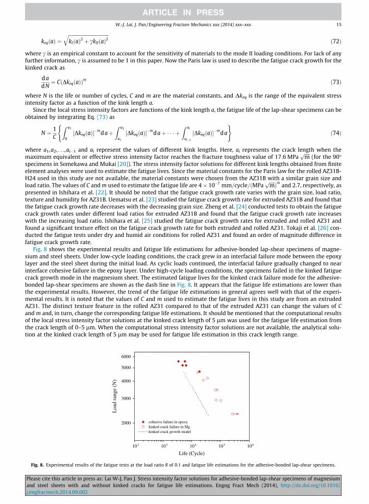
Fig.
W.-J. Lai, J. Pan / Engineering Fracture Mechanics xxx (2014) xxx–xxx 15
Pleaseand sj.engfr
keqðaÞ ¼ffiffiffiffiffiffiffiffiffiffiffiffiffiffiffiffiffiffiffiffiffiffiffiffiffiffiffiffiffiffiffiffiffiffikIðaÞ2 þ ckIIðaÞ2
qð72Þ
where c is an empirical constant to account for the sensitivity of materials to the mode II loading conditions. For lack of anyfurther information, c is assumed to be 1 in this paper. Now the Paris law is used to describe the fatigue crack growth for thekinked crack as
dadN¼ CðDkeqðaÞÞm ð73Þ
where N is the life or number of cycles, C and m are the material constants, and Dkeq is the range of the equivalent stressintensity factor as a function of the kink length a.
Since the local stress intensity factors are functions of the kink length a, the fatigue life of the lap-shear specimens can beobtained by integrating Eq. (73) as
N ¼ 1C
Z a1
0½DkeqðaÞ��mdaþ
Z a2
a1
½DkeqðaÞ��mdaþ � � � þZ ai
ai�1
½DkeqðaÞ��mda
( )ð74Þ
where a1,a2, . . .,ai�1 and ai represent the values of different kink lengths. Here, ai represents the crack length when themaximum equivalent or effective stress intensity factor reaches the fracture toughness value of 17:6 MPa
ffiffiffiffiffimp
(for the 90�specimens in Somekawa and Mukai [20]). The stress intensity factor solutions for different kink lengths obtained from finiteelement analyses were used to estimate the fatigue lives. Since the material constants for the Paris law for the rolled AZ31B-H24 used in this study are not available, the material constants were chosen from the AZ31B with a similar grain size andload ratio. The values of C and m used to estimate the fatigue life are 4� 10�7 mm=cycle=ðMPa
ffiffiffiffiffimpÞm and 2.7, respectively, as
presented in Ishihara et al. [22]. It should be noted that the fatigue crack growth rate varies with the grain size, load ratio,texture and humidity for AZ31B. Uematsu et al. [23] studied the fatigue crack growth rate for extruded AZ31B and found thatthe fatigue crack growth rate decreases with the decreasing grain size. Zheng et al. [24] conducted tests to obtain the fatiguecrack growth rates under different load ratios for extruded AZ31B and found that the fatigue crack growth rate increaseswith the increasing load ratio. Ishihara et al. [25] studied the fatigue crack growth rates for extruded and rolled AZ31 andfound a significant texture effect on the fatigue crack growth rate for both extruded and rolled AZ31. Tokaji et al. [26] con-ducted the fatigue tests under dry and humid air conditions for rolled AZ31 and found an order of magnitude difference infatigue crack growth rate.
Fig. 8 shows the experimental results and fatigue life estimations for adhesive-bonded lap-shear specimens of magne-sium and steel sheets. Under low-cycle loading conditions, the crack grew in an interfacial failure mode between the epoxylayer and the steel sheet during the initial load. As cyclic loads continued, the interfacial failure gradually changed to nearinterface cohesive failure in the epoxy layer. Under high-cycle loading conditions, the specimens failed in the kinked fatiguecrack growth mode in the magnesium sheet. The estimated fatigue lives for the kinked crack failure mode for the adhesive-bonded lap-shear specimens are shown as the dash line in Fig. 8. It appears that the fatigue life estimations are lower thanthe experimental results. However, the trend of the fatigue life estimations in general agrees well with that of the experi-mental results. It is noted that the values of C and m used to estimate the fatigue lives in this study are from an extrudedAZ31. The distinct texture feature in the rolled AZ31 compared to that of the extruded AZ31 can change the values of Cand m and, in turn, change the corresponding fatigue life estimations. It should be mentioned that the computational resultsof the local stress intensity factor solutions at the kinked crack length of 5 lm was used for the fatigue life estimation fromthe crack length of 0–5 lm. When the computational stress intensity factor solutions are not available, the analytical solu-tion at the kinked crack length of 5 lm may be used for fatigue life estimation in this crack length range.
102 103 104 105 106
2000
3000
4000
5000
6000
cohesive failure in epoxy kinked crack failure in Mg kinked crack growth model
Loa
d ra
nge
(N)
Life (Cycle)
8. Experimental results of the fatigue tests at the load ratio R of 0.1 and fatigue life estimations for the adhesive-bonded lap-shear specimens.
cite this article in press as: Lai W-J, Pan J. Stress intensity factor solutions for adhesive-bonded lap-shear specimens of magnesiumteel sheets with and without kinked cracks for fatigue life estimations. Engng Fract Mech (2014), http://dx.doi.org/10.1016/acmech.2014.09.002
16 W.-J. Lai, J. Pan / Engineering Fracture Mechanics xxx (2014) xxx–xxx
Based on the linear elastic fracture mechanics, the plastic zone size of the kinked crack in the magnesium sheet undercyclic loading conditions at the time when the effective local stress intensity factor reaches the fracture toughness of17:6 MPa
ffiffiffiffiffimp
(or 10:8 MPaffiffiffiffiffimp
) are small compared to the crack lengths of interest. Therefore, the use of linear elastic frac-ture mechanics and the kinked crack growth model for the fatigue life estimations is reasonable in this study. Based on thebeam bending theory, the magnesium sheet is yielded substantially at the maximum load of 5144 N for the load range of4630 N (the largest load range that resulted in the kinked crack failure mode) due to the combined tension and bending.However, the magnesium sheet near the right main crack tip was under elastic loading and unloading condition after theinitial loading since the stress range for elastic loading and unloading is quite large due to the large yield stress of AZ31.The plastic flow near the crack tip is due to the singular behavior near the crack tip. Therefore, the fatigue life estimationsbased on the kinked crack growth model is reasonable with the stress intensity factor solutions.
8. Conclusions
In this paper, stress intensity factor solutions for adhesive-bonded lap-shear specimens of magnesium alloy AZ31 andhot-dip-galvanized (HDG) mild steel sheets with and without kinked cracks are investigated for fatigue life estimations. First,the kinked fatigue crack failure mode of the adhesive-bonded lap-shear specimens is briefly reviewed. Then, the analyticalglobal J integral and effective stress intensity factor solutions for main cracks in lap-shear specimens of three dissimilarsheets under plane strain conditions are developed based on the beam bending theory. The global effective stress intensityfactor solutions for the main cracks in the lap-shear specimens from the corresponding finite element analyses are then pre-sented and validated by the analytical solutions.
Next, the local stress intensity factor solutions for kinked cracks with the experimentally observed kink angle as functionsof the kink length from the corresponding finite element analyses are presented and the computational solutions are alsocompared with the analytical solutions at small kink lengths. The results indicate that the computational local stress inten-sity factor solutions for kinked cracks approach to the analytical solutions as the kink length decreases to a very small valueand the kinked crack is under dominant mode I loading conditions. The computational results also indicate that the localstress intensity factor solutions at a small kink length of microstructural significance may be used as the stress intensity fac-tor solutions for zero or near zero kink length for fatigue life estimations when the computational results are not available.
Finally, the computational local stress intensity factor solutions are adopted to estimate the fatigue lives of the lap-shearspecimens based on a kinked crack growth model and available material constants for the Paris law. The fatigue life estima-tions are lower than the experimental results. However, the general trend of fatigue life estimations agrees with that of theexperimental results.
Acknowledgements
This research was sponsored by the U.S. Department of Energy, Assistant Secretary for Energy Efficiency and RenewableEnergy, Office of Vehicle Technologies, as part of the Lightweight Materials Program. Helpful discussion with Drs. Tsung-YuPan, Michael Santella and Zhili Feng of Oak Ridge National Laboratory and Dr. Teresa Rinker of General Motors are greatlyappreciated.
References
[1] Santella M, Franklin T, Pan J, Pan T-Y, Brown E. Ultrasonic spot welding of AZ31B to galvanized mild steel. SAE Int J Mater Manuf 2010;3:652–7.[2] Hetrick E, Jahn R, Reatherford L. Ultrasonic spot welding: a new tool for aluminum joining. Weld J 2005;84:26–30.[3] Jahn R, Cooper R, Wilkosz D. The effect of anvil geometry and welding energy on microstructures in ultrasonic spot welds of AA6111-T4. Metall Mater
Trans A 2007;38:570–83.[4] Wright NW, Robson JD, Prangnell PB. Effects of thickness combinations on joint properties and process windows in ultrasonic metal welding. SAE
technical paper no. 2009-01-0027. Warrendale, PA: Society of Automotive Engineers; 2009.[5] Watanabe A, Watanabe T, Sasaki T. Ultrasonic welding mild steel sheet to Al–Mg alloy sheet. Adv Mater Res 2010;89–91:627–32.[6] Franklin T, Pan J, Santella M, Pan T-Y. Fatigue behavior of dissimilar ultrasonic spot welds in lap-shear specimens of magnesium and steel sheets. SAE
Int J Mater Manuf 2011;4:581–8.[7] Lai W-J, Pan J, Feng Z, Santella M, Pan T-Y. Failure mode and fatigue behavior of ultrasonic spot welds with adhesive in lap-shear specimens of
magnesium and steel sheets. SAE Int J Mater Manuf 2013;6:279–85.[8] Franklin T. Fatigue behavior and life estimation for dissimilar ultrasonic welds in lap-shear specimens of magnesium and galvanized steel sheets
[dissertation]. Ann Arbor (MI): University of Michigan; 2013.[9] Cotterell B, Rice JR. Slightly curved or kinked cracks. Int J Fract 1980;16:155–69.
[10] He M-Y, Hutchinson JW. Kinking of a crack out of an interface. J Appl Mech 1989;56:270–8.[11] Zhang S. Stress intensities derived from stresses around a spot weld. Int J Fract 1999;99:239–57.[12] Rice JR. A path independent integral and the approximate analysis of strain concentration by notches and cracks. J Appl Mech 1968;35:379–86.[13] Wang D-A, Lin P-C, Pan J. Geometric functions of stress intensity factor solutions for spot welds in lap-shear specimens. Int J Solids Struct
2005;42:6299–318.[14] Wang D-A, Lin S-H, Pan J. Stress intensity factors for spot welds and associated kinked cracks in cup specimens. Int J Fatigue 2005;27:581–98.[15] Lin P-C, Pan J. Closed-form structural stress and stress intensity factor solutions for spot welds in commonly used specimens. Engng Fract Mech
2008;75:5187–206.[16] Rice JR, Sih GC. Plane problems of cracks in dissimilar media. J Appl Mech 1965;32:418–23.[17] Rice JR. Elastic fracture mechanics concepts for interfacial cracks. J Appl Mech 1988;55:98–103.[18] ABAQUS v6.12 user manual. Providence. RI: SIMULIA; 2012.[19] He M-Y, Hutchinson JW. Kinking of a crack out of an interface. tabulated solution coefficients. Harvard University Report MECH-113A; 1988.
Please cite this article in press as: Lai W-J, Pan J. Stress intensity factor solutions for adhesive-bonded lap-shear specimens of magnesiumand steel sheets with and without kinked cracks for fatigue life estimations. Engng Fract Mech (2014), http://dx.doi.org/10.1016/j.engfracmech.2014.09.002
W.-J. Lai, J. Pan / Engineering Fracture Mechanics xxx (2014) xxx–xxx 17
[20] Somekawa H, Mukai T. Fracture toughness in a rolled AZ31 magnesium alloy. J Alloys Compd 2006;417:209–13.[21] Broek D. Elementary engineering fracture mechanics. 4th ed. Martinus Nijhoff Publisher; 1986.[22] Ishihara S, McEvily AJ, Sato M, Taniguchi K, Goshima T. The effect of load ratio on fatigue life and crack propagation behavior of an extruded
magnesium alloy. Int J Fatigue 2009;31:1788–94.[23] Uematsu Y, Tokaji K, Kamakura M, Uchida K, Shibata H, Bekku N. Effect of extrusion conditions on grain refinement and fatigue behaviour in
magnesium alloys. Mater Sci Engng A 2006;434:131–40.[24] Zheng S, Yu Q, Jiang Y. An experimental study of fatigue crack propagation in extruded AZ31B magnesium alloy. Int J Fatigue 2013;47:174–83.[25] Ishihara S, Taneguchi S, Shibata H, Goshima T, Saiki A. Anisotropy of the fatigue behavior of extruded and rolled magnesium alloys. Int J Fatigue
2013;50:94–100.[26] Tokaji K, Nakajima M, Uematsu Y. Fatigue crack propagation and fracture mechanisms of wrought magnesium alloys in different environments. Int J
Fatigue 2009;31:1137–43.
Please cite this article in press as: Lai W-J, Pan J. Stress intensity factor solutions for adhesive-bonded lap-shear specimens of magnesiumand steel sheets with and without kinked cracks for fatigue life estimations. Engng Fract Mech (2014), http://dx.doi.org/10.1016/j.engfracmech.2014.09.002