Embed Size (px)
Citation preview
STRENGTH ANALYSIS OF KINKED CURVE PLATE USED AS ELEMENT OF SYSTEM OF
DEFORMERS IN SOIL CULTIVATORS
Bandurin M.A. Department "General Engineering disciplines"
Platov South-Russian State Polytechnic University (NPI) Novocherkassk, Russia
Mykhailin A.A. Department "General Engineering disciplines"
Platov South-Russian State Polytechnic University (NPI) Novocherkassk, Russia
Nefedov V.V. Department "General Engineering disciplines"
Platov South-Russian State Polytechnic University (NPI) Novocherkassk, Russia
Abstract— The existing soil cultivators have a number of shortcomings. The authors suggest calculation for elements of the system of deformers in soil cultivators represented as plates with kinked curves. The paper explores a possibility of lengthening of horizontal elements of the system of deformers in rack of chizel type deep tiller without losses in its strength and without any significant changes in its thickness. The initial task is to calculate strained-deformed state of isotropic plates with kinked profile, clamped medial edges, symmetrically positioned on the vertical rack, inclined towards the vertical axis, having the same strength and uniform cross-section along the whole length (volumetric task). Numerical studies show zones that could possibly bear similar types of characteristic damages providing a possibility to design a kinked curve plate with optimal thickness, fracture angle and tilt angle. It is also found that the most dangerous feature is the decrease in the actual thickness of plate of more than 1/3 of computed thickness, thus leading to breakdown of a separate piece of the detail.
Keywords— calculation of strength, deep tiller, system of deformers, stress, strain, bending, kinked curve plate, clamped edges, geometric characteristics
I. INTRODUCTION
Current state of affairs shows various constructions of deep tilling soil cultivators, thus for instance including inclined racks, inclined racks with cropping elements – the chisel type deep tillers. There are known soil cultivators with a closed contour system of deformers – voluminous tillers. Such tillers have up to 3 m operating width with generally up to 0,5 m tillage depth, whereby the tillage depth may be extended up to 0,6 m (and up to 0,8 m in deep tilling soil cultivators). If the operating width is increased, the amount of racks also rises leading to a significant increase of mass of the gear with increase in draught resistance. Existing tools providing the necessary operating width and quality of tillage often have low
reliability and inacceptable high energy loading. Moreover, the possibilities of deep tilling with depth of 50 cm and more are more limited. Shall the operating width be increased for a mounted deep tilling chisel type soil cultivator the horizontal elements of system of deformers also become drawn which leads to loss in their strength properties. Therefore a calculation is necessary to define the elements of systems of deformers in deep tilling soil cultivators represented as bended plates or plates with kinked curve. Let us consider the kinked curve plates, because they produce more deformations in the depth of processed soil layer, therefore the quality of soil crumbling is higher. Let us analyze at a first approximation as follows: what is the most possible extent for drawing of the tilling horizontal elements of the system of deformers in the rack of deep tilling chisel type soil cultivator without losses in their strength and significant change of their geometric characteristics. [1-3]
II. THEORY
Let us assume horizontal parts of the system of deformers in the deep tilling chisel type soil cultivator with extended operating width to be kinked curve plates symmetrically positioned on each side of rack. The correspondent task at a first approximation consists of calculation of strained-deformed state of isotropic plates having kinked profile with clamped edges, symmetrically positioned on vertical rack, inclined towards the vertical axis, having the same strength and uniform cross-section along the whole length (volumetric task). Contemporary methods and solutions were not applied to the full extent for this statement of a question.
The examined shape of the kinked curve plates is shown on the following figure 1 (providing that the angles are as follows: α=0, β=450, γ=900).
International Conference on Aviamechanical Engineering and Transport (AviaENT 2018)
Copyright © 2018, the Authors. Published by Atlantis Press. This is an open access article under the CC BY-NC license (http://creativecommons.org/licenses/by-nc/4.0/).
Advances in Engineering Research, volume 158
267
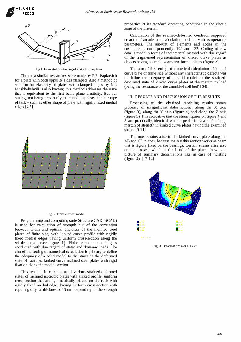
Fig.1. Estimated positioning of kinked curve plates
The most similar researches were made by P.F. Papkovich for a plate with both opposite sides clamped. Also a method of solution for elasticity of plates with clamped edges by N.I. Muskhelishvili is also known; this method addresses the issue that is equivalent to the first basic plane elasticity. But our setting, not being previously examined, supposes another type of task – such as other shape of plate with rigidly fixed medial edges [4,5].
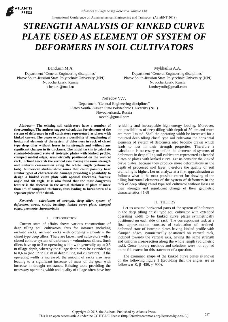
Fig. 2. Finite element model
Programming and computing suite Structure CAD (SCAD) is used for calculation of strength out of the correlation between width and optimal thickness of the inclined steel plates of finite size, with kinked curve profile with rigidly fixed medial edges having uniform cross-section along the whole length (see figure 1). Finite element modeling is conducted with due regard of static and dynamic loads. The aim of the setting of numerical calculation is primary to define the adequacy of a solid model to the strain as the deformed state of isotropic kinked curve inclined steel plates with rigid fixation along the medial section.
This resulted in calculation of various strained-deformed states of inclined isotropic plates with kinked profile, uniform cross-section that are symmetrically placed on the rack with rigidly fixed medial edges having uniform cross-section with equal rigidity, at thickness of 3 mm depending on the strength
properties at its standard operating conditions in the elastic zone of the material.
Calculation of the strained-deformed condition supposed creation of an adequate calculation model at various operating parameters. The amount of elements and nodes of the ensemble is, correspondently, 104 and 132. Coding of raw data is made in terms of incremental method with due regard of the fragmented representation of kinked curve plates as objects having a simple geometric form – plates (figure 2).
The aim of the setting of numerical calculation of kinked curve plate of finite size without any characteristic defects was to define the adequacy of a solid model to the strained-deformed state of kinked curve plates at the maximum load (being the resistance of the crumbled soil bed) [6-8].
III. RESULTS AND DISCUSSION OF THE RESULTS
Processing of the obtained modeling results shows presence of insignificant deformations: along the X axis (figure 3), along the Y axis (figure 4) and along the Z axis (figure 5). It is indicative that the strain figures on figure 4 and 5 are practically identical which speaks in favor of a huge margin of strength in kinked curve plates having the examined shape. [9-11]
The most strains arise in the kinked curve plate along the AB and CD planes, because mainly this section works as beam that is rigidly fixed on the bearings. Certain strains arise also on the “nose”, which is the bend of the plate, showing a picture of summary deformations like in case of twisting (figure 4). [12-14]
Fig. 3. Deformations along X axis
1
β
Z
χ
2
y
α
γ
Advances in Engineering Research, volume 158
268
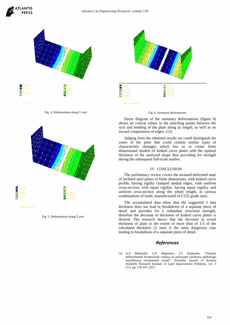
Fig. 4. Deformations along Y axis
Fig. 5. Deformations along Z axis
Fig. 6. Summary deformations
Stress diagram of the summary deformations (figure 6) shows no critical values in the attaching points between the rack and bending of the plate along its length, as well as no inward compression of edges. [15]
Judging from the obtained results we could distinguish the zones of the plate that could contain similar types of characteristic damages which lets us to create finite dimensional models of kinked curve plates with the optimal thickness of the analyzed shape thus providing for strength during the subsequent full-scale studies.
IV. CONCLUSION
The preliminary review covers the strained-deformed state of inclined steel plates of finite dimensions, with kinked curve profile, having rigidly clamped medial edges, with uniform cross-section, with equal rigidity, having equal rigidity and uniform cross-section along the whole length, at various combinations of loads, manufactured of C255 grade steel.
The accumulated data show that the suggested 3 mm thickness does not lead to breakdown of a separate piece of detail and provides for a redundant structural strength, therefore the decrease in thickness of kinked curve plates is desired. The research shows that the decrease in actual thickness of plate to the extent of more than of 1/3 of the calculated thickness (3 mm) is the most dangerous case leading to breakdown of a separate piece of detail.
References
[1] A.A Mikhaylin. V.P. Maksimov, I.V. Klimenko, “Vliyanie
tekhnicheskih harakteristik orudiya na pokazateli kachestva glubokogo razryhleniya oroshaemyh zemel”, Scientific Journal of Russian Scientific Research Institute of Land Improvement Problems, vol. 3 (11). рр. 134-147, 2013.
Advances in Engineering Research, volume 158
269
[2] A.A. Mikhaylin, M.A. Bandurin, S.V. Filonov, “K voprosu ob opredelenii parametrov oblasti razryhleniya”, Injenerny vestnik Dona, vol. 4-2 (39), p. 13, 2015.
[3] A. Kulen, H. Kujpers Sovremennaja zemledel'cheskaja mehanika. Moskva: Agropromizdat, 1986. р. 349.
[4] A.N. Zelenin, Mashiny dlja zemljanyh rabot. Moskva: Mashinostroenie, 1975. рр. 424.
[5] De Vita P., Di Paolo E., Fecondo G. [and other], “No-tillage and conventional tillage effects on durum wheat yield, grain quali-ty and soil moisture content in southern Italy“, Soil & Tillage Research, vol. 92 (1-2). pp. 69-78, 2007.
[6] L.A. Smith, “Williford Power Requirements of Convention, Triplex and Para-bolic Subsoilers”, Transactions on the ASAE, vol.6, pp. 1686-1688, 1988.
[7] Amato G., Ruisi P., Frenda A.S. [and other] “Long-term tillage and crop sequence effects on wheat grain field and quality”, Agronomy Journal, vol. 105 (5), pp. 1317-1327, 2013.
[8] A.E. Docenko, I.B. Borisenko, “Optimizacija konstruktivnyh i tehnologicheskih parametrov otval'no-chizel'nogo rabochego organa”. 9 mezhdunarodnaja konferencija, vol. 1, рр.82-88, December 2015 [Razvitie nauki v 21 veke, p. 438, 2015].
[9] I.B. Borisenko, “Sovershenstvovanie resursosberegajushhih i pochvozashhitnyh tehnologij i tehnicheskih sredstv obrabotki pochvy
ostrozasushlivyh uslovijah Nizhnego Povolzh'ja”. Volgograd, 2006. рр. 173-200.
[10] I.B. Borisenko, A. E. Docenko, “Agrotehnologicheskie podhody pri proektirovanii rabochih organov dlja osnovnoj glubokoj obrabotki pochvy”, Poisk innovacionnyh putej, рр. 123-130, May 2014 [Poisk innovacionnyh putej, p. 360, 2014]/
[11] A.A Mikhaylin, “Analiz ustojchivosti obrabatyvaemyh vlagonasyshchennyh sklonovyh pochv”, Injenerny vestnik, vol. 4, p. 38, 2012/
[12] S.P. Timoshenko, S. Vojnovskij-Kriger, Plastinki i obolochki. Moskva: Fizmatgiz, 1963. рр. 14-60.
[13] V.M. Darevskij, I.L. Sharinov “Novoe reshenie zadachi ob izgibe za-shhemlennoj po krajam prjamougol'noj plastinki”, Uspehi mehaniki deformiruemyh sred, Moskva: Nauka, 1975, рр. 183– 194.
[14] S.A. Lychev, S.V. Saleev “Zamknutoe reshenie zadachi ob izgibe zhestko zakreplennoj prjamougol'noj plastiny”, Vestn. Samar.gos. un–ta, vol. 2, рр. 62–73, 2006/
[15] S.A. Halilov, V.B. Mintjuk, D.A. Tkachenko, “Postroenie i issledovanie analitiko-chislennogo reshenija zadachi ob izgibe zhestko zashhemlennoj prjamougol'noj plastiny”, Otkrytye informacionnye i komp'juternye integrirovannye tehnologii, vol 49, рр. 81–94, 2011.
Advances in Engineering Research, volume 158
270