Embed Size (px)
Citation preview
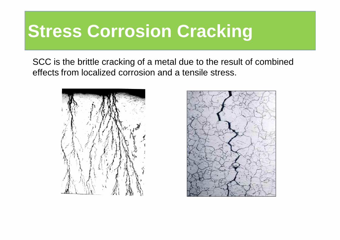
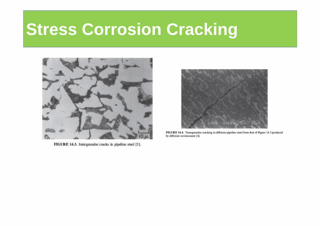
SCC is the brittle cracking of a metal due to the result of combined effects from localized corrosion and a tensile stress.
Stress Corrosion Cracking
Stress Corrosion Cracking
Stress Corrosion Cracking
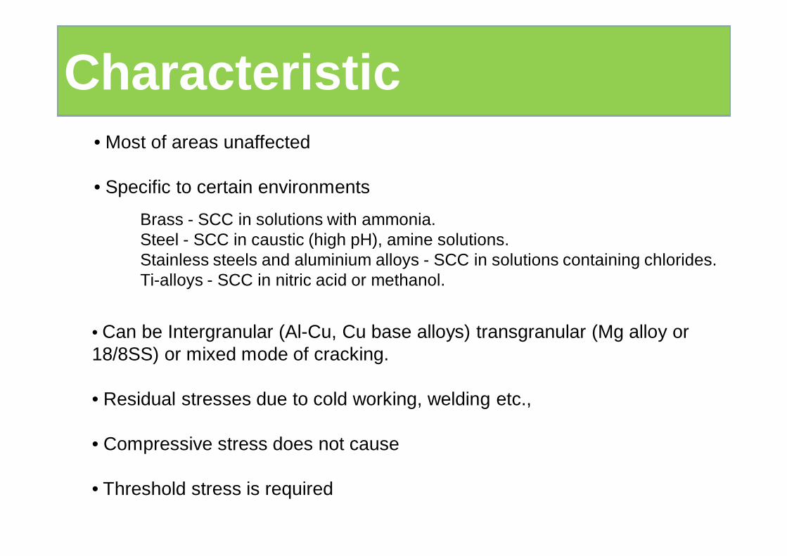
• Can be Intergranular (Al-Cu, Cu base alloys) transgranular (Mg alloy or 18/8SS) or mixed mode of cracking.
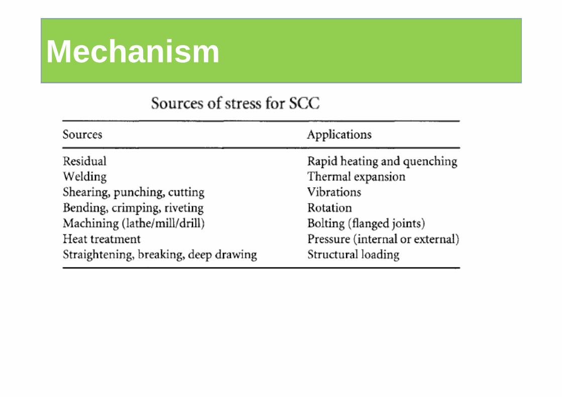
• Residual stresses due to cold working, welding etc.,
• Compressive stress does not cause
• Threshold stress is required
• Most of areas unaffected
• Specific to certain environments
Brass - SCC in solutions with ammonia.Steel - SCC in caustic (high pH), amine solutions.Stainless steels and aluminium alloys - SCC in solutions containing chlorides.Ti-alloys - SCC in nitric acid or methanol.
Characteristic
Mechanism
Mechanism
Mechanism
Mechanism
Mechanism
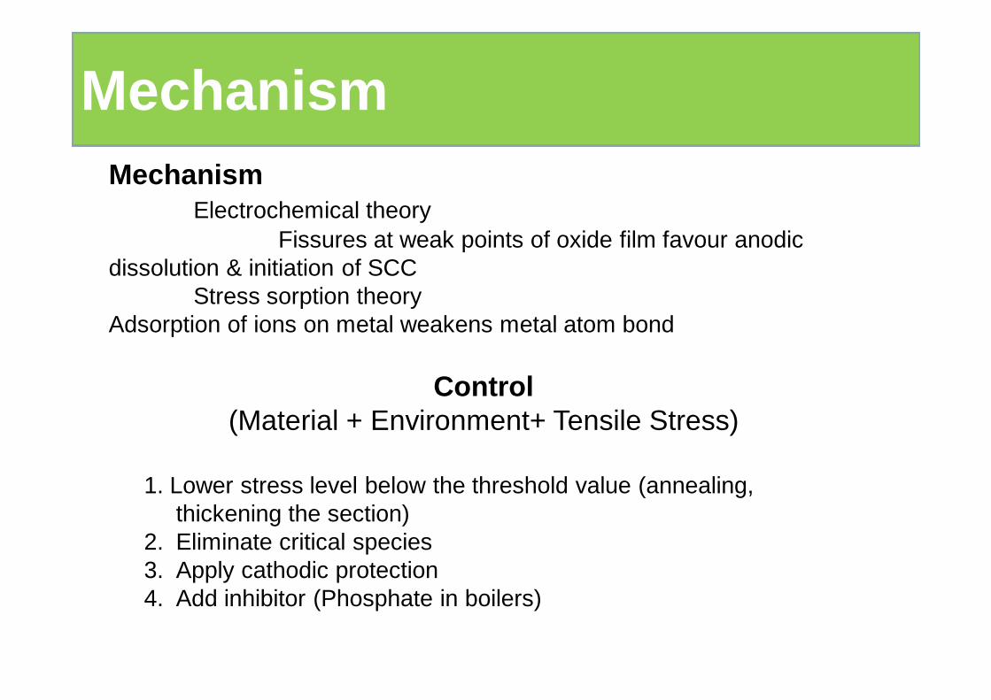
Control(Material + Environment+ Tensile Stress)
1. Lower stress level below the threshold value (annealing, thickening the section)
2. Eliminate critical species3. Apply cathodic protection4. Add inhibitor (Phosphate in boilers)
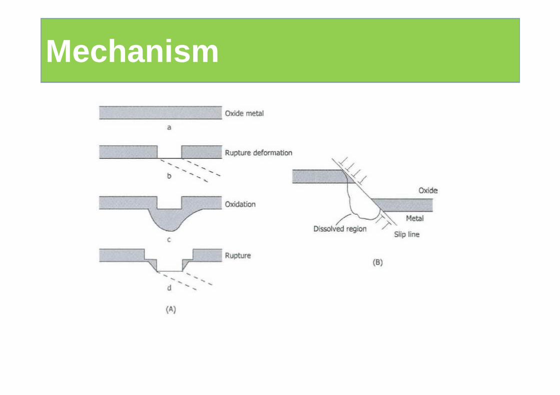
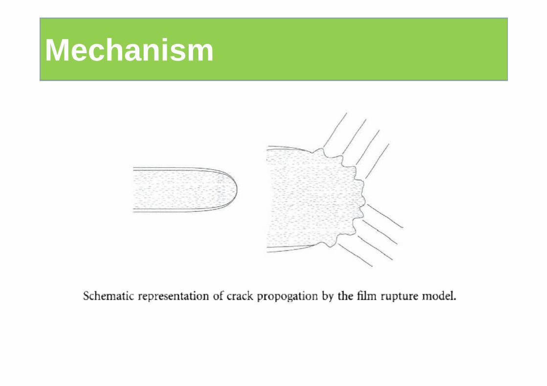
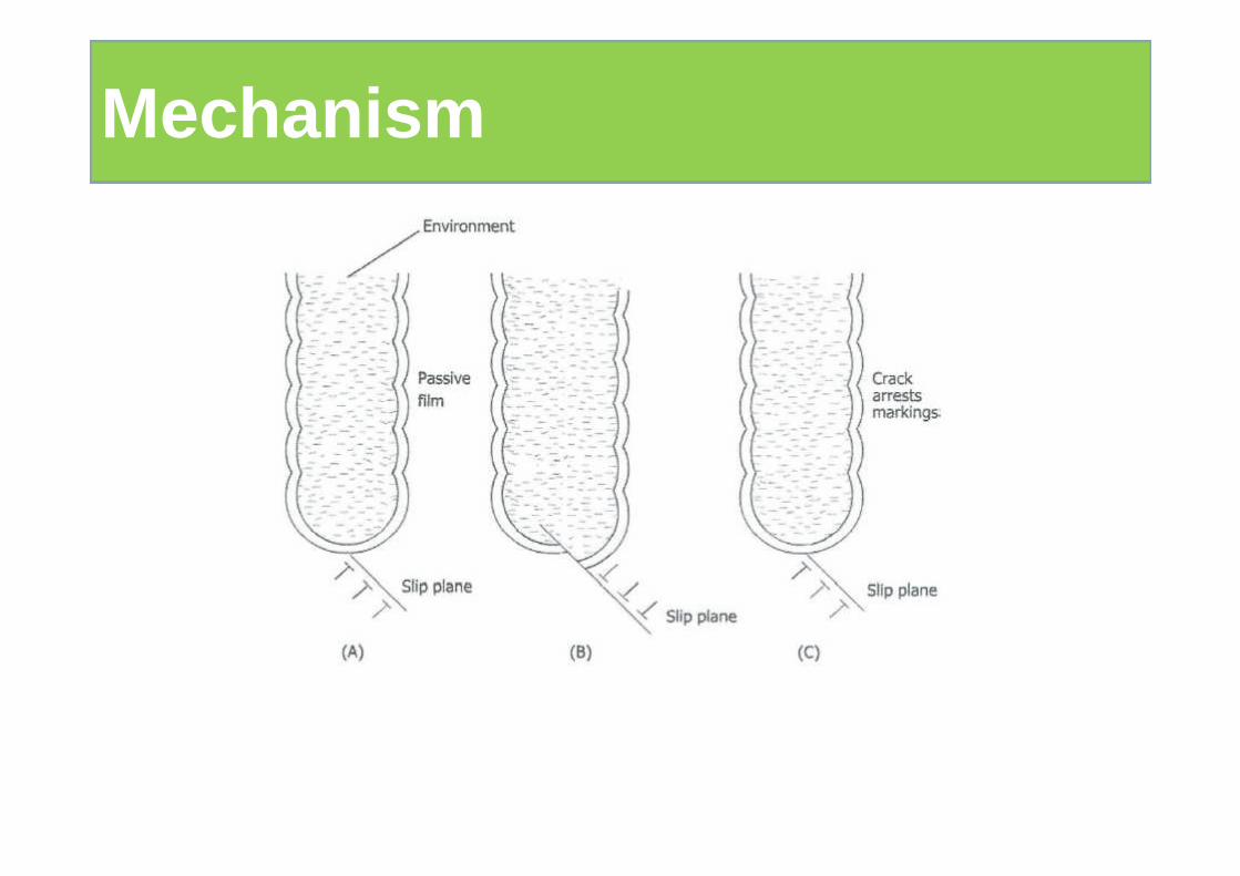
MechanismElectrochemical theory
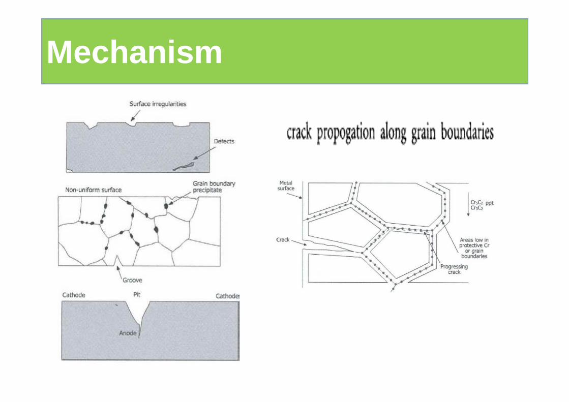
Fissures at weak points of oxide film favour anodic dissolution & initiation of SCC
Stress sorption theoryAdsorption of ions on metal weakens metal atom bond
Mechanism
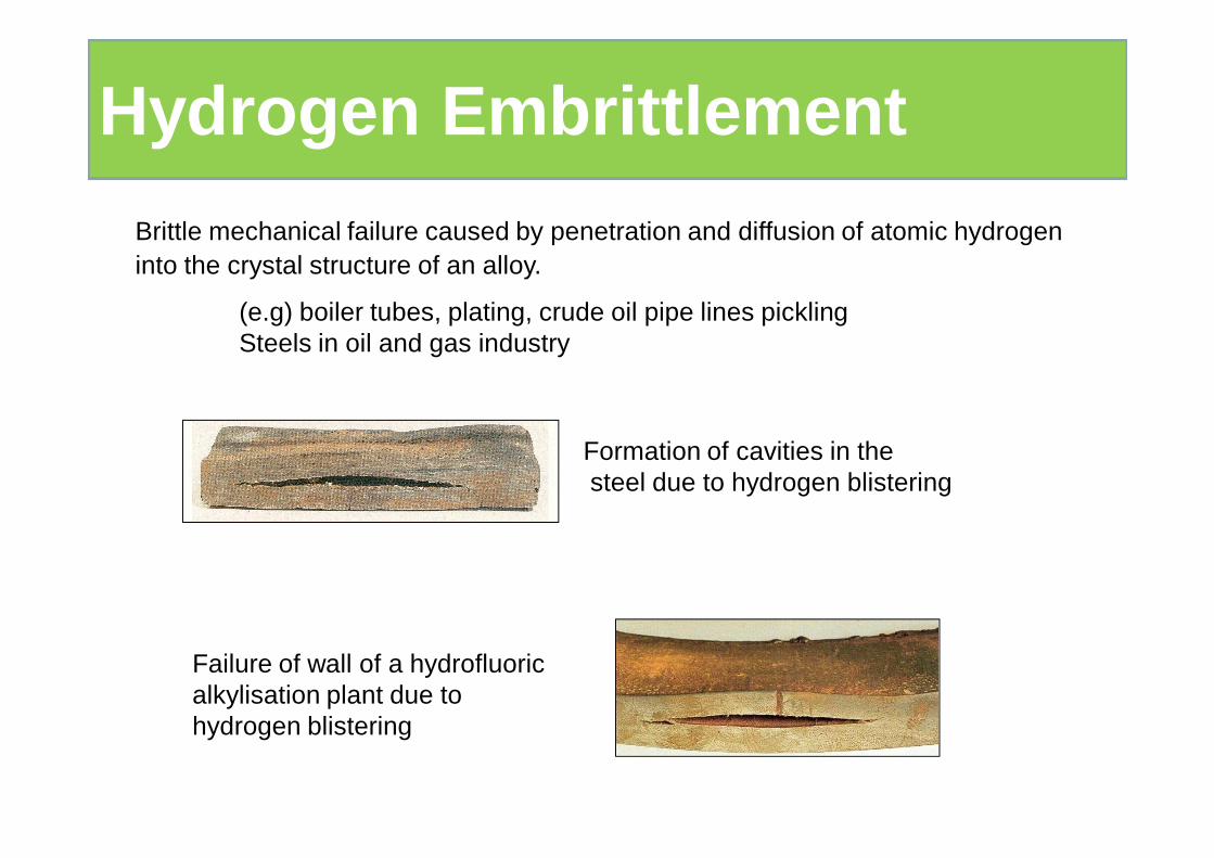
Failure of wall of a hydrofluoric alkylisation plant due to hydrogen blistering
Formation of cavities in thesteel due to hydrogen blistering
Brittle mechanical failure caused by penetration and diffusion of atomic hydrogen into the crystal structure of an alloy.
(e.g) boiler tubes, plating, crude oil pipe lines picklingSteels in oil and gas industry
Hydrogen Embrittlement
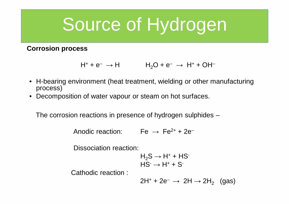
The corrosion reactions in presence of hydrogen sulphides –
Anodic reaction: Fe → Fe2+ + 2e–
Dissociation reaction: H2S → H+ + HS-
HS- → H+ + S-
Cathodic reaction :2H+ + 2e– → 2H → 2H2 (gas)
Corrosion process
H+ + e– → H H2O + e– → H+ + OH–
• H-bearing environment (heat treatment, wielding or other manufacturing process)
• Decomposition of water vapour or steam on hot surfaces.
Source of Hydrogen
Hydrogen Induced Cracking (HIC ) – The corrosion damage is in the form of blisters and / or internal cracks in absence of STRESS
Sulfide stress Cracking (SSC ) – Presence of STRESS
Posions - Presence of S2- and As3+ delay the recombination of H atoms. P, Sb, Se, Te and Cyanide are other poisons.
Fe (Surface) + H2S (gas) → FeS (Surface) + 2H (solution)
• Weakening of the metallic bond strength by the dissolve H.
• Diffusion of atomic H into metal and forms molecular H2 in voids/defects forms blisters. This build up high pressure causes rupture.
• Diffusion of atomic H into metal and reacts with alloying elements to form brittle hydrides
Prevention of HE
• Modification of environments
• Use of materials resistant to HE (High strength materials with low inclusion/voids)
Mechanism
• Large smooth area and a small corroded area
• Specific to high strength materials
• Transgranular failure
• Endurance limit is decreased by corrosive agent
Brittle failure of an alloy caused by fluctuating stress in a corrosive environment.
(Different from SCC)
(e.g) Sucker rods & drilling rods in oil wells rail vehicle springs, motor shaft working in corrosive environment
Characteristics
Fatigue occurs when a material is subjected to repe ated loading and unloading.
Corrosion Fatigue
• Deep pits are initially formed
• Cracks initiates & propagates across the metal
• The frquency of cyclic stress is important. Lower frequency leads to greater crack propagation per cycle.
• Lowering the general corrosion rate will delay or prevent CF.
• Addition of inhibitors
• Barrier coating (Coating Zn, Cr, Ni, Cu & nitride)
• Reduce cyclic stresses by shot peening
Prevention
Mechanism
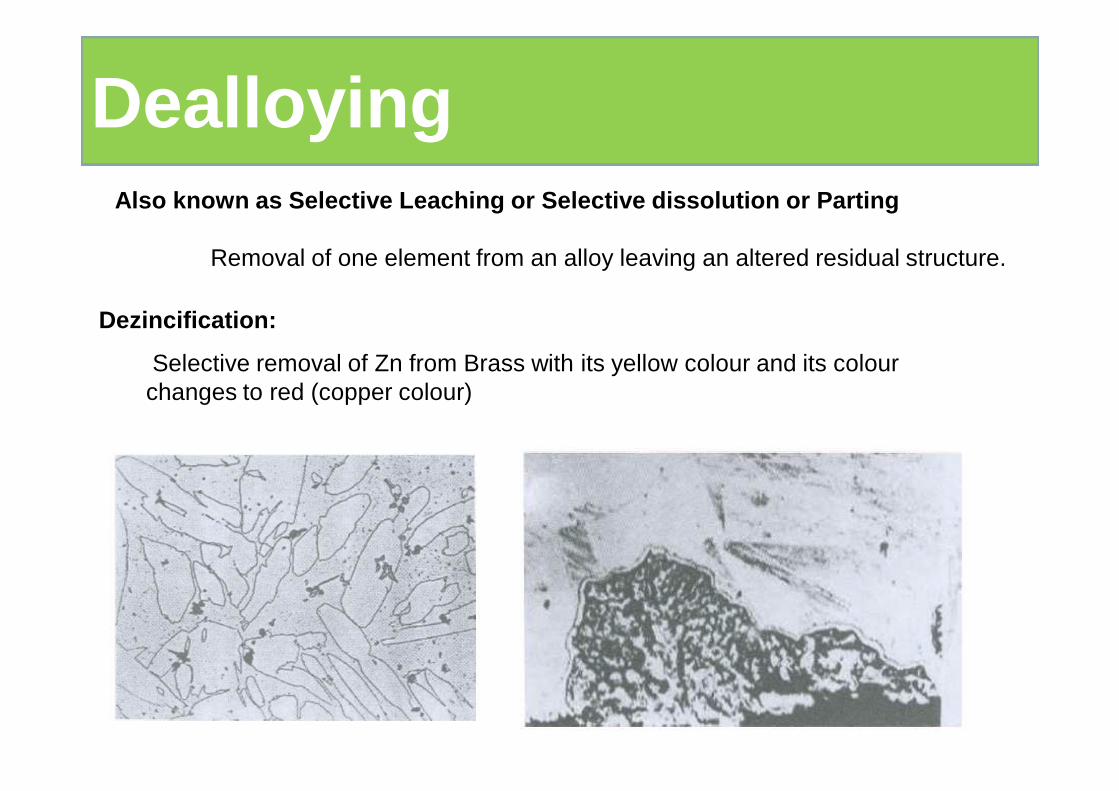
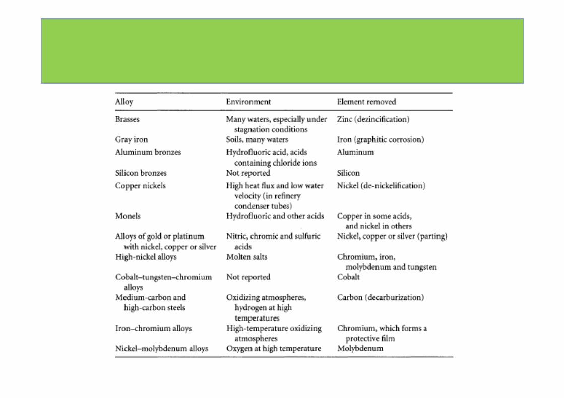
Also known as Selective Leaching or Selective disso lution or Parting
Removal of one element from an alloy leaving an altered residual structure.
Dezincification:
Selective removal of Zn from Brass with its yellow colour and its colourchanges to red (copper colour)
Dealloying
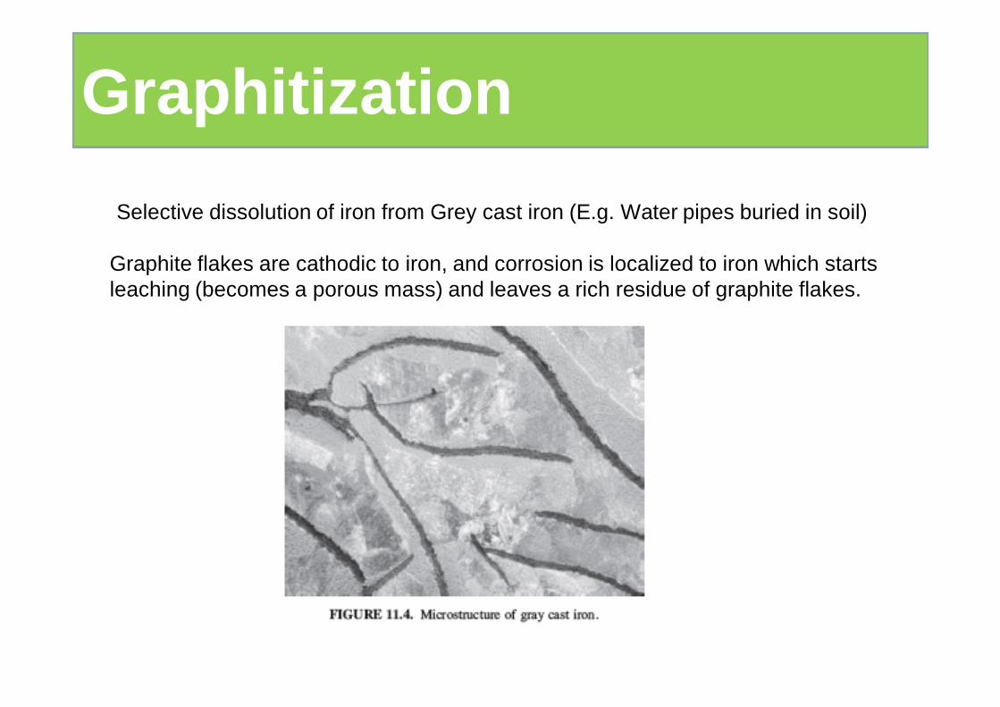
Selective dissolution of iron from Grey cast iron (E.g. Water pipes buried in soil)
Graphitization
Graphite flakes are cathodic to iron, and corrosion is localized to iron which starts leaching (becomes a porous mass) and leaves a rich residue of graphite flakes.
Characteristics
• Loss of mechanical strength without change in shape• It leaves a porous structure • White cast iron does not undergo since C is present as Fe3C but leaves behind a network of graphite flakes
MechanismC is present as graphite form Potential difference exists between graphite and ironLocal cell promotes corrosion of iron.
Prevention Coal – tar epoxy coating on metal to prevent graphitizationTackling at desgin stageCupro-nickel or addition of 1% Sn to 70-30 brass reduces.Addition of 2% Al to Brass also prevents
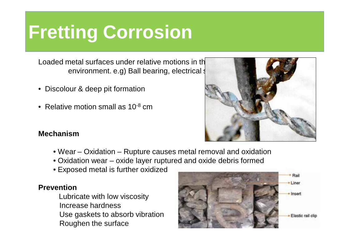
Loaded metal surfaces under relative motions in the presence of corrosive environment. e.g) Ball bearing, electrical switch gear
• Discolour & deep pit formation
• Relative motion small as 10-8 cm
Mechanism
• Wear – Oxidation – Rupture causes metal removal and oxidation• Oxidation wear – oxide layer ruptured and oxide debris formed • Exposed metal is further oxidized
PreventionLubricate with low viscosityIncrease hardnessUse gaskets to absorb vibrationRoughen the surface
Fretting Corrosion
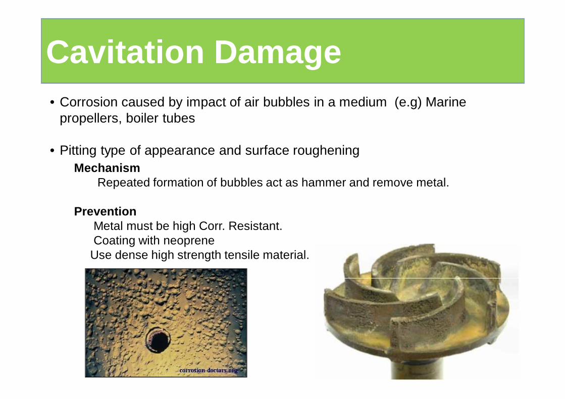
MechanismRepeated formation of bubbles act as hammer and remove metal.
PreventionMetal must be high Corr. Resistant.Coating with neoprene
Use dense high strength tensile material.
• Corrosion caused by impact of air bubbles in a medium (e.g) Marine propellers, boiler tubes
• Pitting type of appearance and surface roughening
Cavitation Damage
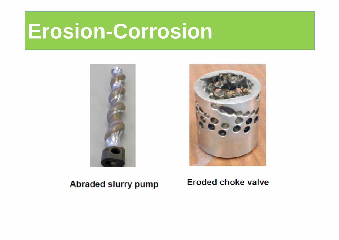
Erosion-Corrosion
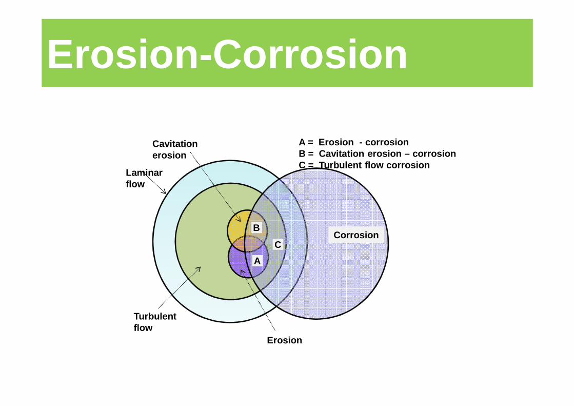
Erosion-Corrosion
Corrosion
A
B
C
Laminar flow
Cavitationerosion
Turbulent flow
Erosion
A = Erosion - corrosionB = Cavitation erosion – corrosion C = Turbulent flow corrosion
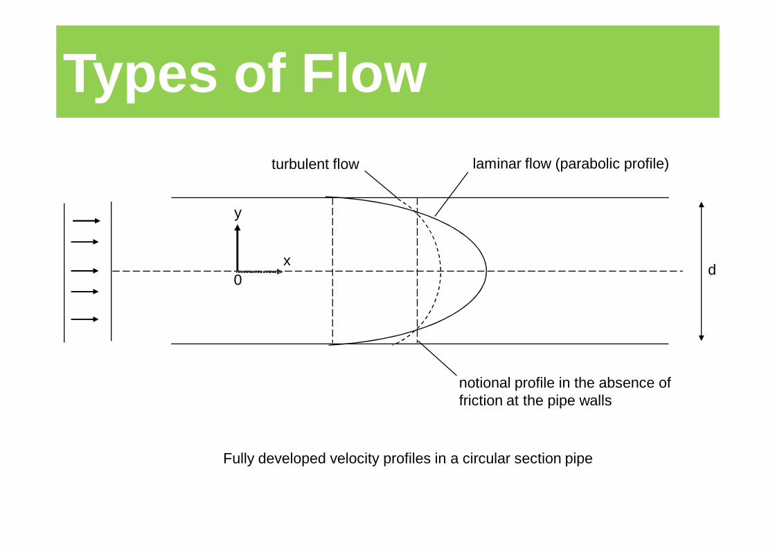
0
y
xd
notional profile in the absence of friction at the pipe walls
laminar flow (parabolic profile)turbulent flow
Fully developed velocity profiles in a circular section pipe
Types of Flow
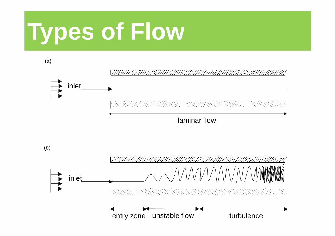
entry zone unstable flow turbulence
laminar flow
inlet
inlet
(a)
(b)
Types of Flow
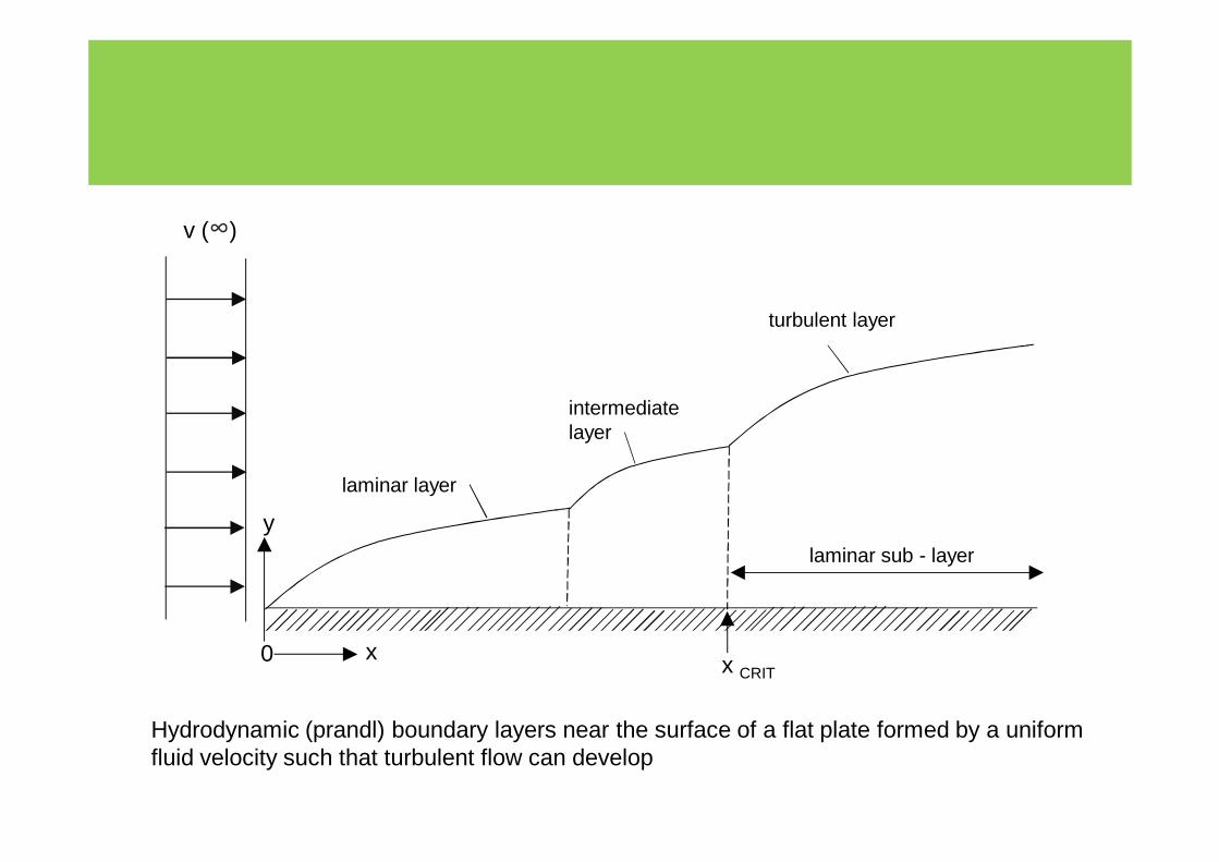
v (∞)
laminar layer
intermediate layer
turbulent layer
laminar sub - layer
y
x0 x CRIT
Hydrodynamic (prandl) boundary layers near the surface of a flat plate formed by a uniform fluid velocity such that turbulent flow can develop
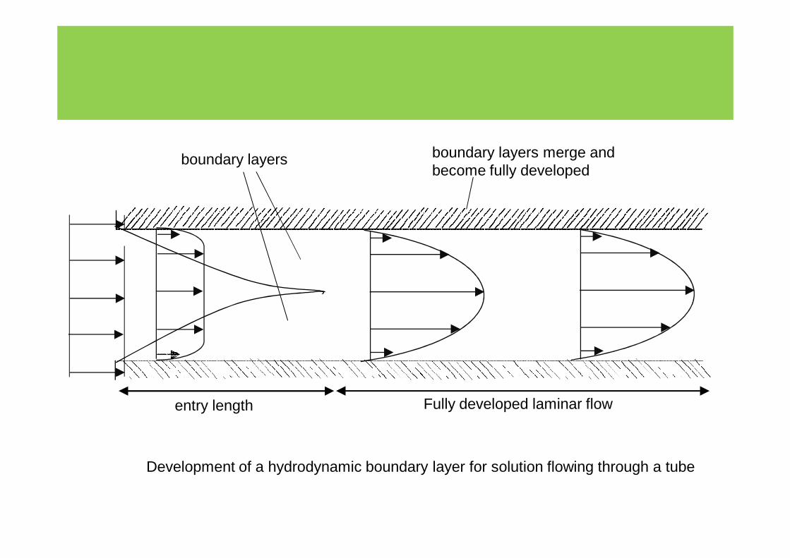
entry length Fully developed laminar flow
boundary layers boundary layers merge and become fully developed
Development of a hydrodynamic boundary layer for solution flowing through a tube
0 1 2 3 4
Cor
rosi
on r
ate
mm
/yea
r
0.0
0.2
0.4
0.6
0.8
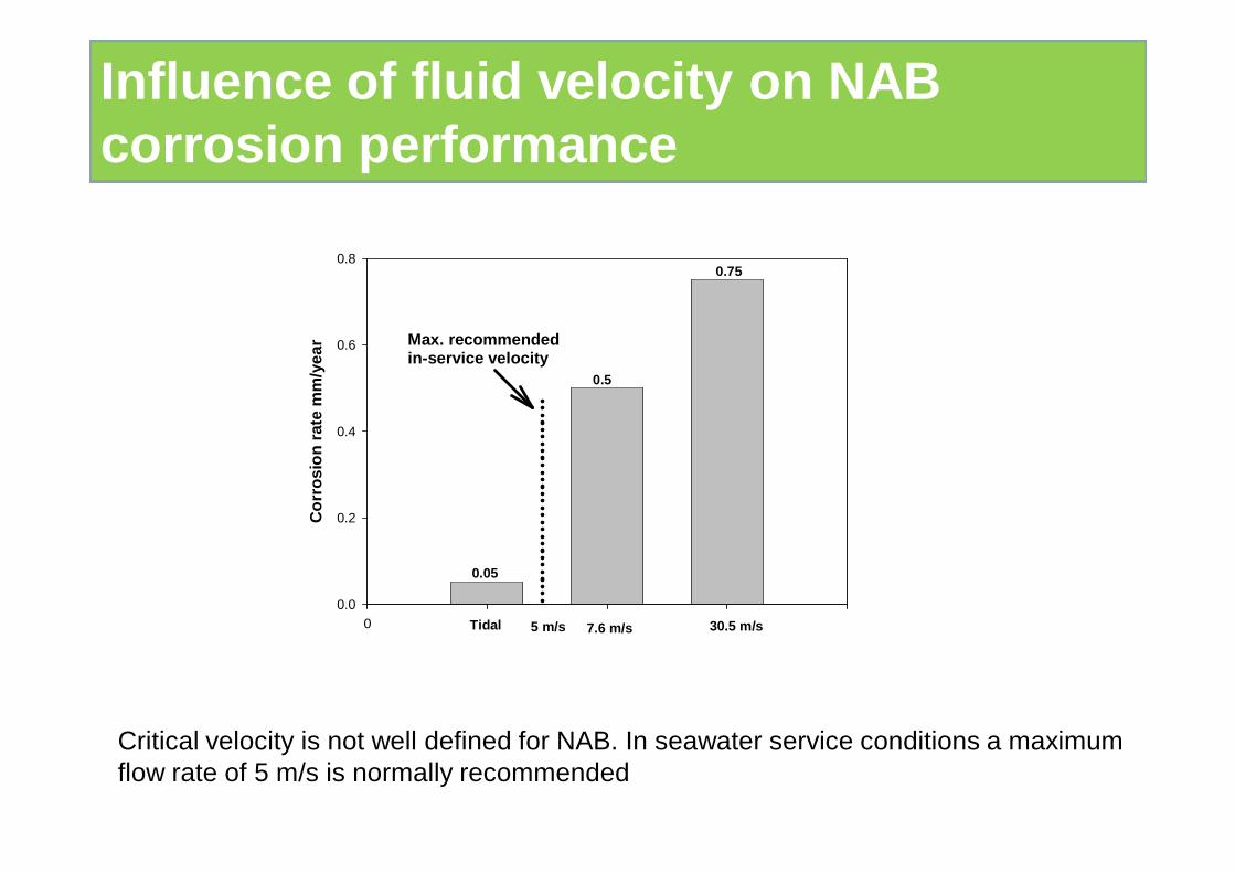
Tidal 7.6 m/s 30.5 m/s
0.05
0.5
0.75
5 m/s
Max. recommendedin-service velocity
Critical velocity is not well defined for NAB. In seawater service conditions a maximum flow rate of 5 m/s is normally recommended
Influence of fluid velocity on NAB corrosion performance
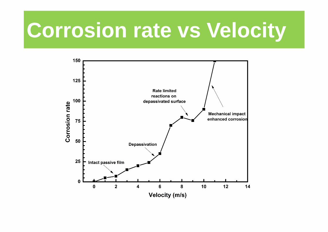
Corrosion rate vs Velocity
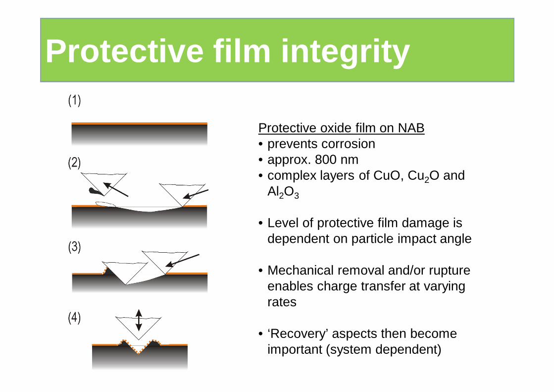
Protective oxide film on NAB• prevents corrosion• approx. 800 nm• complex layers of CuO, Cu2O and
Al2O3
• Level of protective film damage is dependent on particle impact angle
• Mechanical removal and/or rupture enables charge transfer at varying rates
• ‘Recovery’ aspects then become important (system dependent)
Protective film integrity
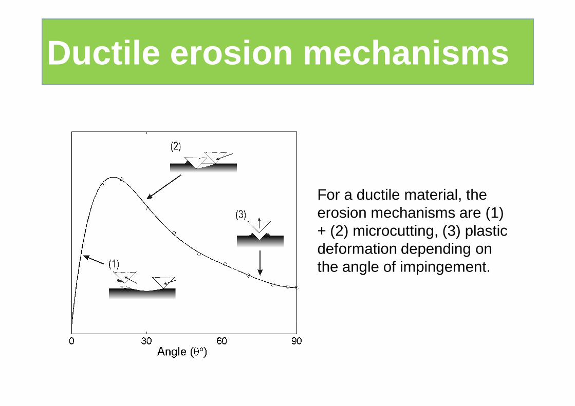
For a ductile material, the erosion mechanisms are (1) + (2) microcutting, (3) plastic deformation depending on the angle of impingement.
Ductile erosion mechanisms
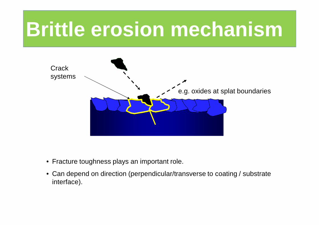
Crack systems
• Fracture toughness plays an important role.
• Can depend on direction (perpendicular/transverse to coating / substrate interface).
e.g. oxides at splat boundaries
Brittle erosion mechanism
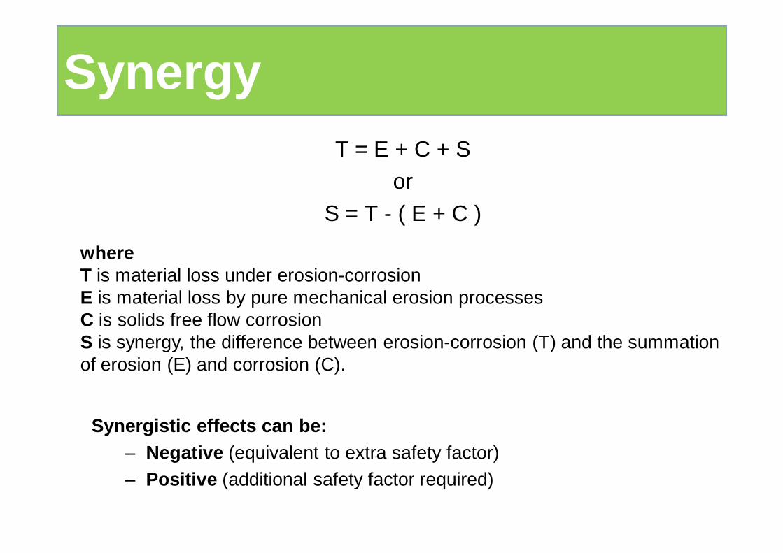
T = E + C + Sor
S = T - ( E + C )
whereT is material loss under erosion-corrosion E is material loss by pure mechanical erosion processesC is solids free flow corrosion S is synergy, the difference between erosion-corrosion (T) and the summation of erosion (E) and corrosion (C).
Synergistic effects can be:– Negative (equivalent to extra safety factor)
– Positive (additional safety factor required)
Synergy
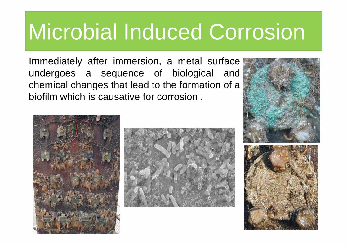
Zero Resistance AmmeterMicrobial Induced CorrosionImmediately after immersion, a metal surfaceundergoes a sequence of biological andchemical changes that lead to the formation of abiofilm which is causative for corrosion .
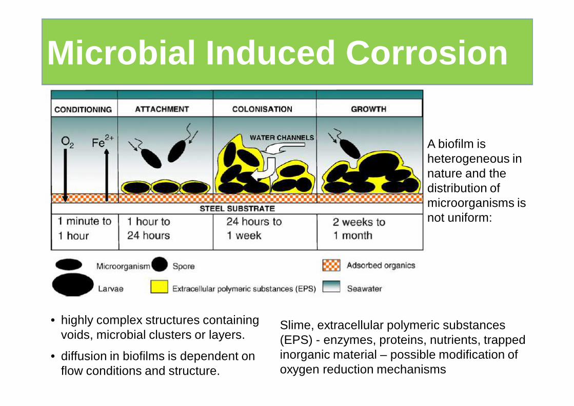
• highly complex structures containing voids, microbial clusters or layers.
• diffusion in biofilms is dependent on flow conditions and structure.
A biofilm is heterogeneous in nature and the distribution of microorganisms is not uniform:
Slime, extracellular polymeric substances (EPS) - enzymes, proteins, nutrients, trapped inorganic material – possible modification of oxygen reduction mechanisms
Microbial Induced Corrosion
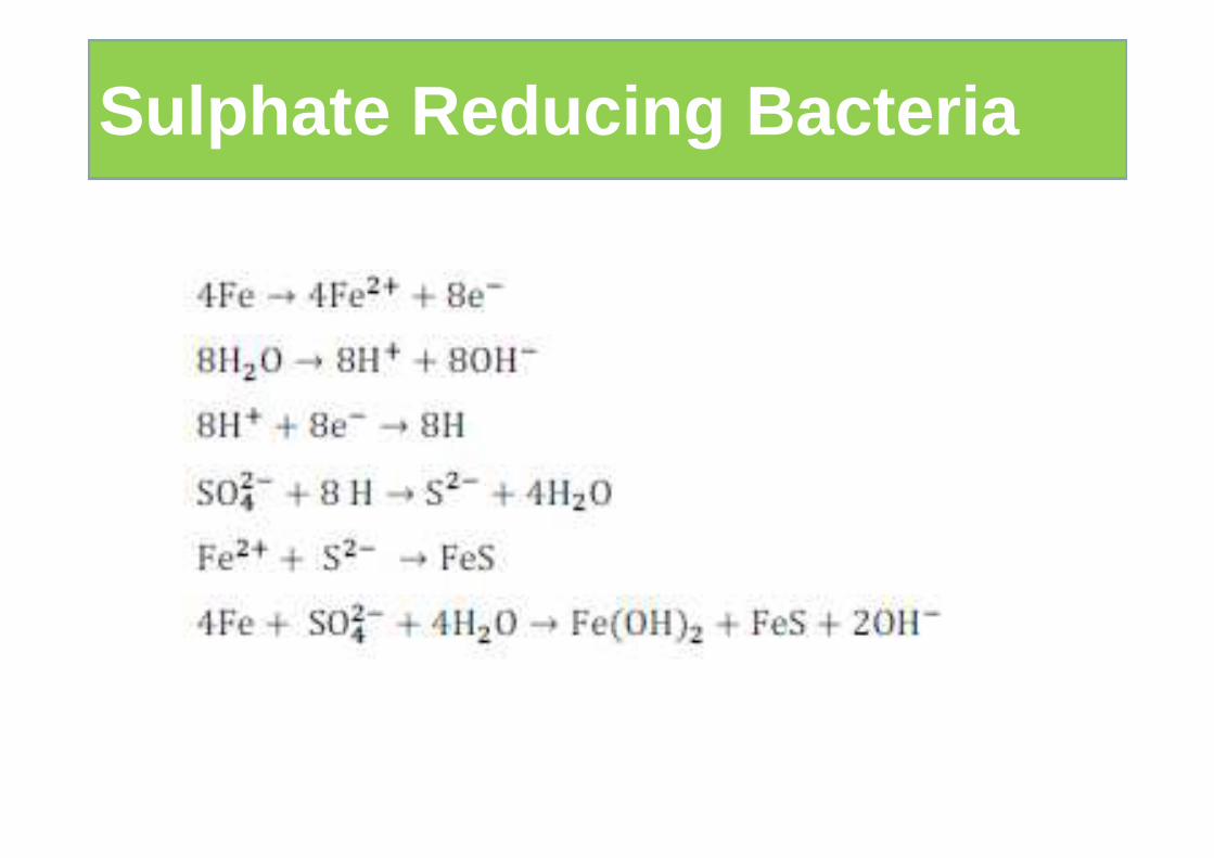
Sulphate Reducing Bacteria
Copper alloys are more resistant to biofouling than most metals due to the toxicity of the released copper-ions.
When coupled to other metals the release of copper-ions can be greatly reduced.
The ennoblement of passive metals, such as titanium and stainless steels is well-documented:
• This ennoblement has been related to the formation of aerobic biofilms, although the mechanism governing the processes is still a subject of much debate.
• Biofilms on titanium have been reported to catalyse the cathodic reduction of oxygen – thus increasing the overall cathodic efficiency.
Biofilms and galvanic corrosion
References
• S.N.Banerjee, “An Introduction to Corrosion Science and Corrosion Inhibition”, Oxonian Press P.Ltd., New Delhi, 1985.
• Zaki Ahmad, “Principles of Corrosion Engineering & Corrosion Control”, ButterworthHeinemann, 2006.
• M.G.Fontana & N.D. Greene, “Corrosion Engineering”, McGraw Hill, New York , 1978.
• L.L.Shrier “Corrosion”, Vol. I & II, Butterworth Heinemann, 1994.
• H.H.Uhlig and R.W.Revie, “Corrosion and Corrosion Control”, A Wiley – Inter Science Publication John Wiley & Sons, New York, 3rd Edition, 1985
and etc.