Embed Size (px)
Citation preview
Stress Corrosion Cracking Issues in Syngas Plants that may be Missed by
Risk-Based Assessment* Stress corrosion cracking has been causing problems in syngas plants since they were first developed and many of these cases have been covered in previous ammonia safety conferences. Advancement in plant design, increase in knowledge, and the use of appropriate materials have successfully reduced the occurrence of many problems. However, stress corrosion cracking continues to be a problem in aging plants and must be considered when completing a risk-based inspection program or setting
integrity operating windows. Case studies on chloride SCC below 60°C (140°F), chloride SCC under support plates, pure water SCC of Inconel 600 and polythionic SCC of 304 are provided. In each case
these damage processes could be easily missed in an RBI assessment.
*Published by the AIChE Annual Safety in Ammonia Plants and Related Facilities Conference 2014
D. M. Firth, Metallurgist and C. W. Thomas, Metallurgist Quest Integrity Group New Zealand
Manoj Thakur Peter Tait Hotdo Pasaribu CSBP Limited Australia Methanex KPA
Introduction tress corrosion cracking has been causing problems in syngas plants since they were first developed, and many of these have been covered in previous ammonia
safety conferences. Advancement in plant design, increase in knowledge, and the use of appropriate materials have successfully reduced the occurrence of problems such as caustic cracking in steam systems, deaerator cracking, CO/CO2 cracking in CO2 removal systems, and anhydrous ammonia SCC of carbon steels in storage tanks and transport vessels. However, stress corrosion cracking continues to be a problem in aging plants and must be considered
when completing risk based inspection (RBI) program or setting operating windows. This paper presents a series of case studies on stress corrosion cracking that has occurred in locations which may not normally have been considered when defining a RBI test programs. It also discusses mitigation strategies that can be put into place to control risks.
Chloride SCC below 60°C
Typically during the RBI of austenitic stainless steel equipment an established guide rule used is that chloride SCC only occurs above 60°C (140°F), and that the level of chloride required
S
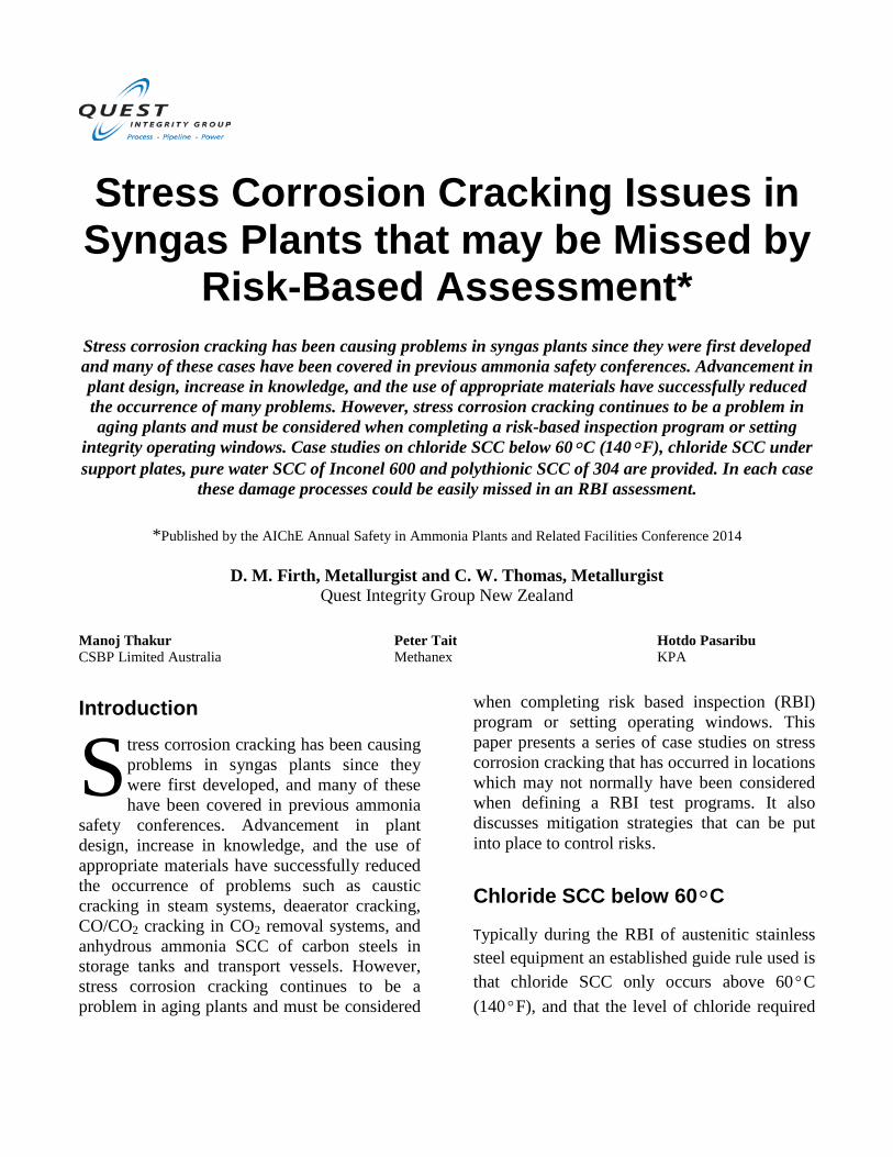
to cause SCC reduces rapidly as the temperature increases. This rule was used in the RBI of all the pressure equipment and piping in the Methanex Motunui 1 and Motunui 2 and Waitara Valley Methanol plants. These plants are located in New Zealand next to the sea where there are commonly high winds, high humidity and it is relatively warm. These conditions have been shown to be optimal for the initiation of corrosion under insulation (CUI) as well as chloride SCC of stainless steels under insulation (CUISCC). Cracking was observed in 303 stainless steel M18 grade 8F nuts on an 8 inch crude methanol bonnet valve flange that was mounted horizontally (studs vertical), see Figure 1. The methanol is normally at 30°C and the flange and bolts would be cooler. Each of the flange studs had two nuts and the central section of the studs were open to the atmosphere as the bolting ring was outside the gasket ring i.e. this was not a full face gasket. Only the lower nuts were seen to crack. The nuts may have been installed in the 1980’s. Cracking commonly occurred through the apex of the hexagonal heads and not in the thinnest wall section. Examination of the failures revealed that the cracking was classic chloride SCC, see Figure 2. However, the initiation and propagation of the cracking was exacerbated by the following: • Use of free machining steel, see Figure 3, as
the SCC/corrosion initiated and propagated along inclusions.
• Corrosion in the nuts installed under the flanges, see Figure 4. Rain water/wind blow salt had been filling the lower bolt holes and chloride concentration occurred. The corrosion present caused an increase in the hoop stress in the nuts as a result of the
formation of corrosion product and oxide jacking.
• Residual stress in the nut due to the forming process. At the inside of the nut the hardness was 289 HV (20) but the hardness increased to the apex corner of the nuts where the hardness was 345 HV (20). However the Brinell hardness on the end of nuts 240 HB (1000) met the requirements of ASTM194 for 8F nuts.
Corrosion and localised SCC had occurred on the B8 (304) stainless steel studs, see Figure 5. However this damage was confined to the region of the threads.
Figure 1. Cracked M18 grade 8F nuts from bottom of a bonnet valve flange
Examination of nuts in similar locations in the Methanex New Zealand plants revealed that this problem was not isolated, nor confined to a single valve manufacturer, and a plant wide inspection program was instigated.
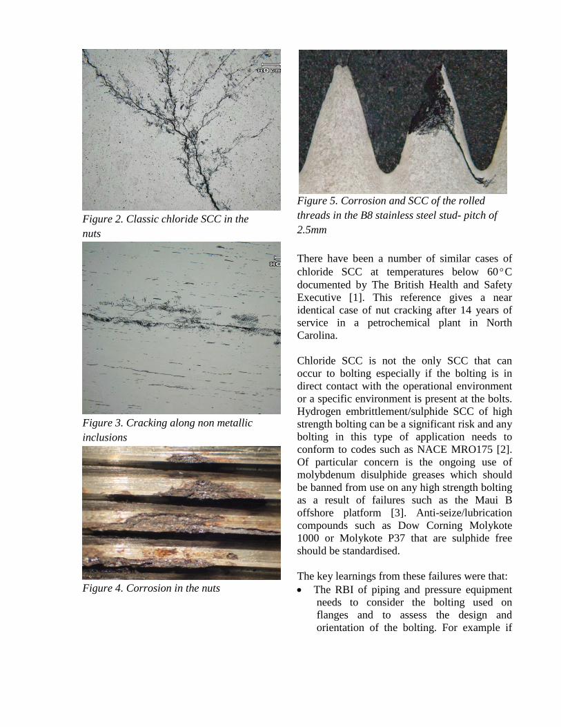
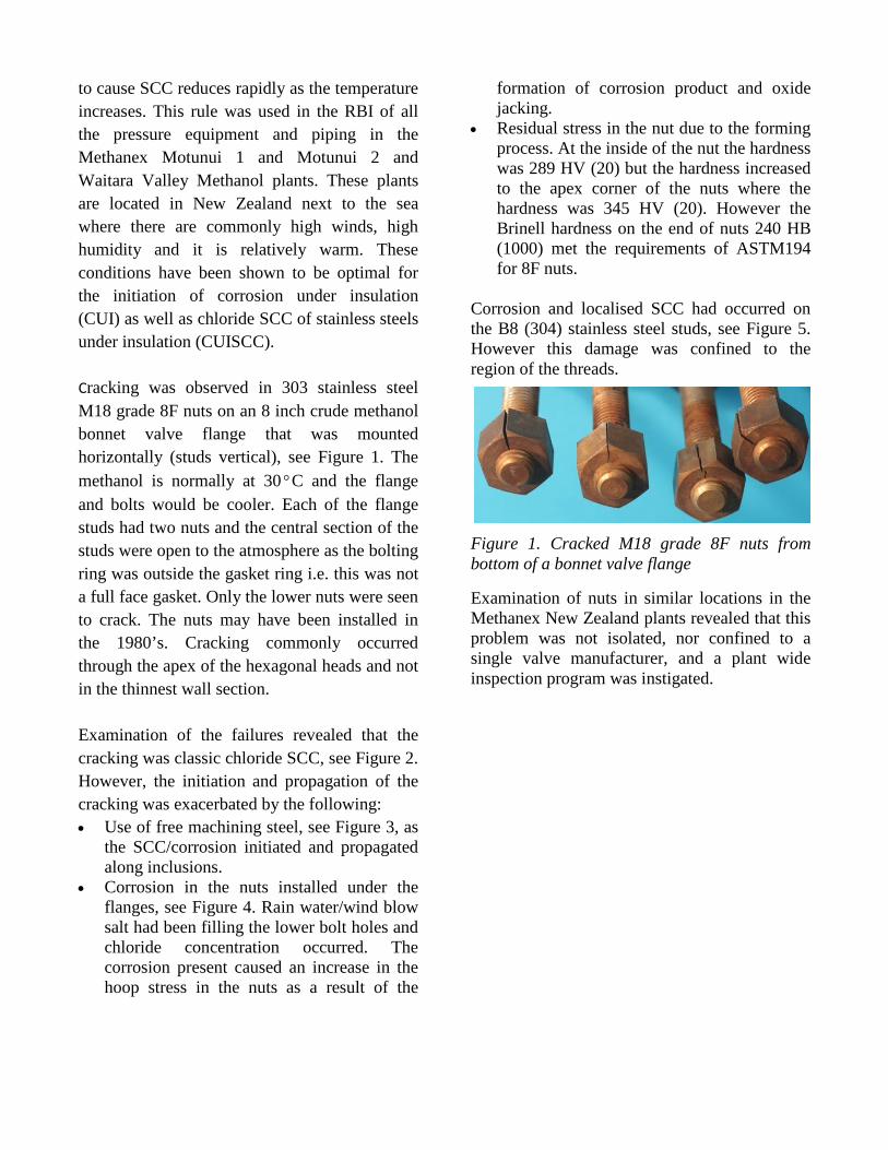
Figure 2. Classic chloride SCC in the nuts
Figure 3. Cracking along non metallic inclusions
Figure 4. Corrosion in the nuts
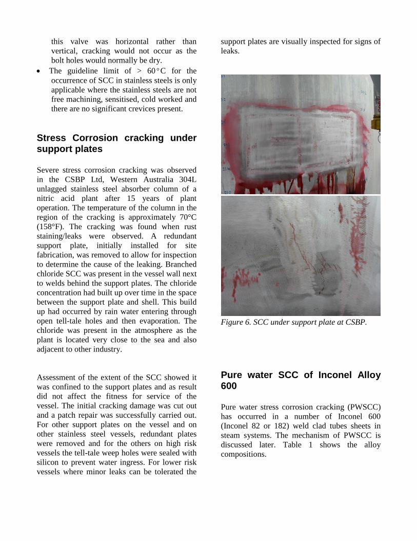
Figure 5. Corrosion and SCC of the rolled threads in the B8 stainless steel stud- pitch of 2.5mm There have been a number of similar cases of chloride SCC at temperatures below 60°C documented by The British Health and Safety Executive [1]. This reference gives a near identical case of nut cracking after 14 years of service in a petrochemical plant in North Carolina.
Chloride SCC is not the only SCC that can occur to bolting especially if the bolting is in direct contact with the operational environment or a specific environment is present at the bolts. Hydrogen embrittlement/sulphide SCC of high strength bolting can be a significant risk and any bolting in this type of application needs to conform to codes such as NACE MRO175 [2]. Of particular concern is the ongoing use of molybdenum disulphide greases which should be banned from use on any high strength bolting as a result of failures such as the Maui B offshore platform [3]. Anti-seize/lubrication compounds such as Dow Corning Molykote 1000 or Molykote P37 that are sulphide free should be standardised. The key learnings from these failures were that: • The RBI of piping and pressure equipment
needs to consider the bolting used on flanges and to assess the design and orientation of the bolting. For example if
this valve was horizontal rather than vertical, cracking would not occur as the bolt holes would normally be dry.
• The guideline limit of > 60°C for the occurrence of SCC in stainless steels is only applicable where the stainless steels are not free machining, sensitised, cold worked and there are no significant crevices present.
Stress Corrosion cracking under support plates Severe stress corrosion cracking was observed in the CSBP Ltd, Western Australia 304L unlagged stainless steel absorber column of a nitric acid plant after 15 years of plant operation. The temperature of the column in the region of the cracking is approximately 70°C (158°F). The cracking was found when rust staining/leaks were observed. A redundant support plate, initially installed for site fabrication, was removed to allow for inspection to determine the cause of the leaking. Branched chloride SCC was present in the vessel wall next to welds behind the support plates. The chloride concentration had built up over time in the space between the support plate and shell. This build up had occurred by rain water entering through open tell-tale holes and then evaporation. The chloride was present in the atmosphere as the plant is located very close to the sea and also adjacent to other industry. Assessment of the extent of the SCC showed it was confined to the support plates and as result did not affect the fitness for service of the vessel. The initial cracking damage was cut out and a patch repair was successfully carried out. For other support plates on the vessel and on other stainless steel vessels, redundant plates were removed and for the others on high risk vessels the tell-tale weep holes were sealed with silicon to prevent water ingress. For lower risk vessels where minor leaks can be tolerated the
support plates are visually inspected for signs of leaks.
Figure 6. SCC under support plate at CSBP. Pure water SCC of Inconel Alloy 600 Pure water stress corrosion cracking (PWSCC) has occurred in a number of Inconel 600 (Inconel 82 or 182) weld clad tubes sheets in steam systems. The mechanism of PWSCC is discussed later. Table 1 shows the alloy compositions.
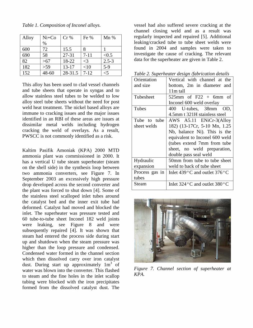
Table 1. Composition of Inconel alloys. Alloy Ni+Co
% Cr % Fe % Mn %
600 72 15.5 8 1 690 58 27-31 7-11 <0.5 82 >67 18-22 <3 2.5-3 182 >59 13-17 <10 5-9 152 48-60 28-31.5 7-12 <5 This alloy has been used to clad vessel channels and tube sheets that operate in syngas and to allow stainless steel tubes to be welded to low alloy steel tube sheets without the need for post weld heat treatment. The nickel based alloys are immune to cracking issues and the major issues identified in an RBI of these areas are issues at dissimilar metal welds including hydrogen cracking the weld of overlays. As a result, PWSCC is not commonly identified as a risk.
Kaltim Pasifik Amoniak (KPA) 2000 MTD ammonia plant was commissioned in 2000. It has a vertical U tube steam superheater (steam on the shell side) in the synthesis loop between two ammonia converters, see Figure 7. In September 2003 an excessively high pressure drop developed across the second converter and the plant was forced to shut down [4]. Some of the stainless steel scalloped inlet tubes around the catalyst bed and the inner exit tube had deformed. Catalyst had moved and blocked the inlet. The superheater was pressure tested and 60 tube-to-tube sheet Inconel 182 weld joints were leaking, see Figure 8 and were subsequently repaired [4]. It was shown that steam had entered the process side during start up and shutdown when the steam pressure was higher than the loop pressure and condensed. Condensed water formed in the channel section which then dissolved carry over iron catalyst dust. During start up approximately 1m3 of water was blown into the converter. This flashed to steam and the fine holes in the inlet scallop tubing were blocked with the iron precipitates formed from the dissolved catalyst dust. The
vessel had also suffered severe cracking at the channel closing weld and as a result was regularly inspected and repaired [5]. Additional leaking/cracked tube to tube sheet welds were found in 2004 and samples were taken to investigate the cause of cracking. The relevant data for the superheater are given in Table 2.
Table 2. Superheater design /fabrication details Orientation and size
Vertical with channel at the bottom, 2m in diameter and 11m tall
Tubesheet 525mm of F22 + 6mm of Inconel 600 weld overlay
Tubes 400 U-tubes, 38mm OD, 4.5mm t 321H stainless steel
Tube to tube sheet welds
AWS A5.11 ENiCr-3(Alloy 182) (13-17Cr, 5-10 Mn, 1.25 Nb, balance Ni). This is the equivalent to Inconel 600 weld (tubes extend 7mm from tube sheet, no weld preparation, double pass seal weld
Hydraulic expansion
50mm from tube to tube sheet weld to back of tube sheet
Process gas in tubes
Inlet 439°C and outlet 376°C
Steam Inlet 324°C and outlet 380°C
Figure 7. Channel section of superheater at KPA.
An adjacent plant to KPA, with the same plant design, has a similar superheater to KPA’s. They were suffering a similar issue at the same time except the extent of tube failures was significantly greater. They found 44% of the 304 tube to tube sheet Inconel 82 welds cracked with one third cracked on the gas inlet and two thirds on the gas outlet side. A significant finding from the testing carried out in both plants showed that neither air leak testing nor dye penetrant testing was reliable at finding the cracking. The most reliable testing techniques were found to be helium leak testing and internal bore UT of the tube to tube sheet welds using tailor made probes.
CSBP have experienced cracking of Inconel 82 tube to tube sheet welds as follows: • Waste heat boiler in the ammonia
converter loop. This high pressure steam boiler has converter effluent in the tubes and water in the shell. Widespread cracking occurred in the tube to tube sheet welds after six months service. The P22 tubes were welded to the Inconel 600 clad tube sheet with Inconel 82. It was found that no PWHT had been applied and the tube HAZ was excessively hard. The cracking probably occurred as a result of hydrogen attack. All the welds were ground off and re-welded with Inconel 82 and PWHT was carried out to reduce the hardness. However after 4 years, a tube leak was found and specialised UT scanning showed that 35% of the tube to tube sheet welds were cracked. Four years later all the tube and tube welds were replaced for a second time. Three years later 63 tube to tube sheet welds were found by UT inspection to have fine root cracks.
• Pre-superheater (first vessel after the converter) in the ammonia converter loop. The vessel was retubed after a year in service as a result of the fabricator using cold worked Inconel 600 tubes which cracked at the U bends. After ten years of
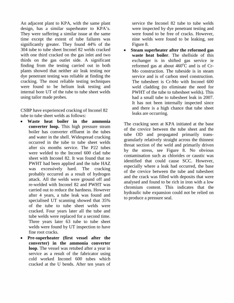
service the Inconel 82 tube to tube welds were inspected by dye penetrant testing and were found to be free of cracks. However, nine welds were found to be leaking, see Figure 8.
• Steam superheater after the reformed gas waste heat boiler. The shellside of this exchanger is in shifted gas service ie reformed gas at about 460oC and is of Cr-Mo construction. The tubeside is in steam service and is of carbon steel construction. The tubesheet is Cr-Mo with Inconel 600 weld cladding (to eliminate the need for PWHT of the tube to tubesheet welds). This had a small tube to tubesheet leak in 2007. It has not been internally inspected since and there is a high chance that tube sheet leaks are occurring.
The cracking seen at KPA initiated at the base of the crevice between the tube sheet and the tube OD and propagated primarily trans-granularly relatively straight across the thinnest throat section of the weld and primarily driven by the stress, see Figure 8. No obvious contamination such as chlorides or caustic was identified that could cause SCC. However, especially where a leak had occurred, the base of the crevice between the tube and tubesheet and the crack was filled with deposits that were analysed and found to be rich in iron with a low chromium content. This indicates that the hydraulic tube expansion could not be relied on to produce a pressure seal.
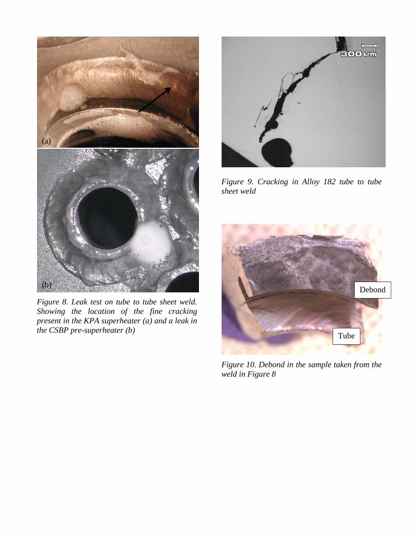
Figure 8. Leak test on tube to tube sheet weld. Showing the location of the fine cracking present in the KPA superheater (a) and a leak in the CSBP pre-superheater (b)
Figure 9. Cracking in Alloy 182 tube to tube sheet weld
Figure 10. Debond in the sample taken from the weld in Figure 8
Debond
Tube
(a)
(b)
In addition to the tube to tubesheet cracking, cracking was also detected on the bond line of the Inconel 182 weld overlay and the F22 tube sheet in the region adjacent to the tubes, see Figure 10. This cracking could be either or both PWSCC and hydrogen cracking along the hard brittle layer at the weld /substrate interface.
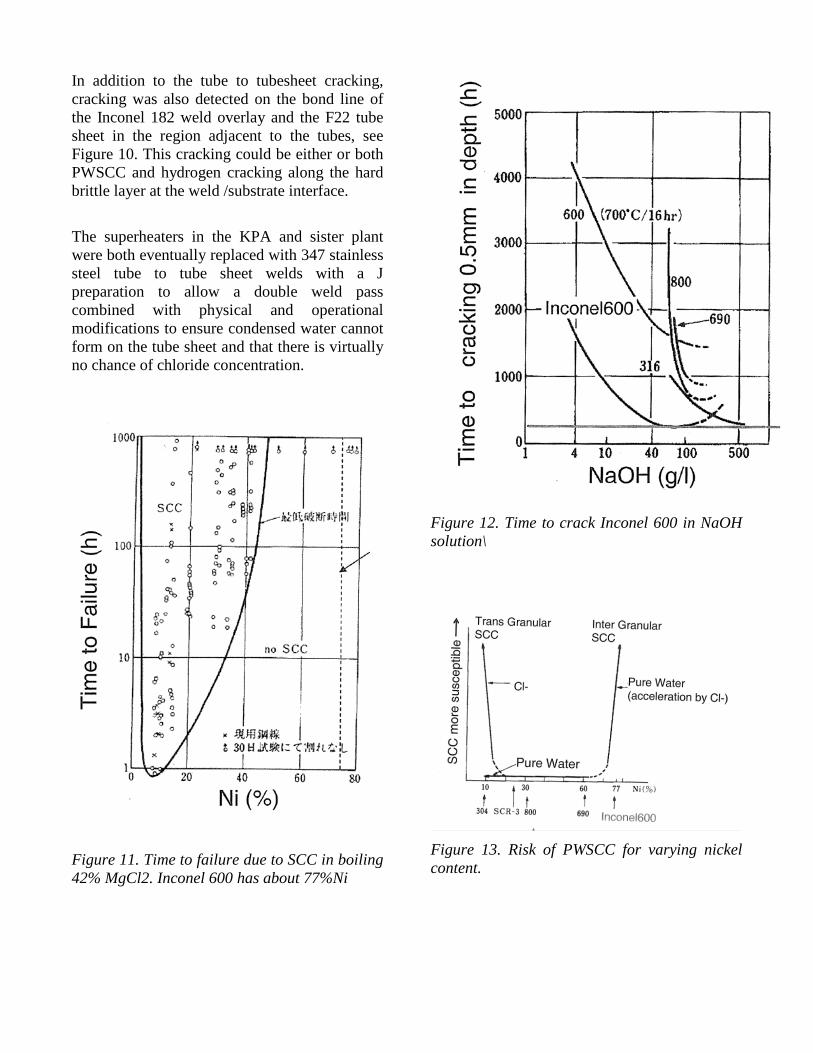
The superheaters in the KPA and sister plant were both eventually replaced with 347 stainless steel tube to tube sheet welds with a J preparation to allow a double weld pass combined with physical and operational modifications to ensure condensed water cannot form on the tube sheet and that there is virtually no chance of chloride concentration.
Figure 11. Time to failure due to SCC in boiling 42% MgCl2. Inconel 600 has about 77%Ni
Figure 12. Time to crack Inconel 600 in NaOH solution\
Figure 13. Risk of PWSCC for varying nickel content.
A review of the possible damage processes at KPA revealed that pure water SCC (PWSCC) was the only possible cause of the cracking. The following were dismissed as being credible: • Chloride SCC as the nickel content is well
above the critical level see Figure 11 and the level of chloride in the boiler water was minimal (<<1ppm).
• Caustic cracking as the concentration required would be excessively high, see Figure 12. Caustic was not used in the process and the boiler water was operated consistently at pH 9-9.5.
• Other boiler chemicals such as volatiles and phosphates causing SCC issues.
• Mechanical load. • Fabrication. • Hydrogen embrittlement from the gas.
However, hydrogen is likely to be associated with the cracking process and to be formed due to surface corrosion.
PWSCC in Inconel 600 with Alloy 182 welds is a common problem in the nuclear power industry. Cases have occurred since 1986 and have resulted in extensive research programs [6,7]. PWSCC tends to be intergranular in wrought alloys and follows the interdendritic of welds. However, the exact mechanism has not been defined [7] but it is known to be dependent on the nickel content, see Figure 13. As a result of the extensive problems Inconel 690 (27-32% Cr, 7-11% Fe, 58% Ni) with Inconel 152 weld material has become the standard to prevent PWSCC in the Nuclear Industry as this alloy has a lower nickel content than the critical level for PWSCC, see Figure 13. Note Inconel 600 has about 72% nickel. However, it is to be noted that Inconel 152 is not as weldable as Inconel 182.
The key learning from these failures is that:
• Any RBI of boilers and superheaters with Inconel 600/Alloy 182 weld material should
identify PWSCC of the tube to tube sheet welds and overlay to substrate interface as a high risk.
• The best method to locate the PWSCC in tube to tube sheet welds is specialised UT from the bore of the tube as this will detect cracking prior to leakage. Helium leak testing is far more reliable than dye penetrant testing and air leak testing to locate through wall cracks in tube to tube sheet welds.
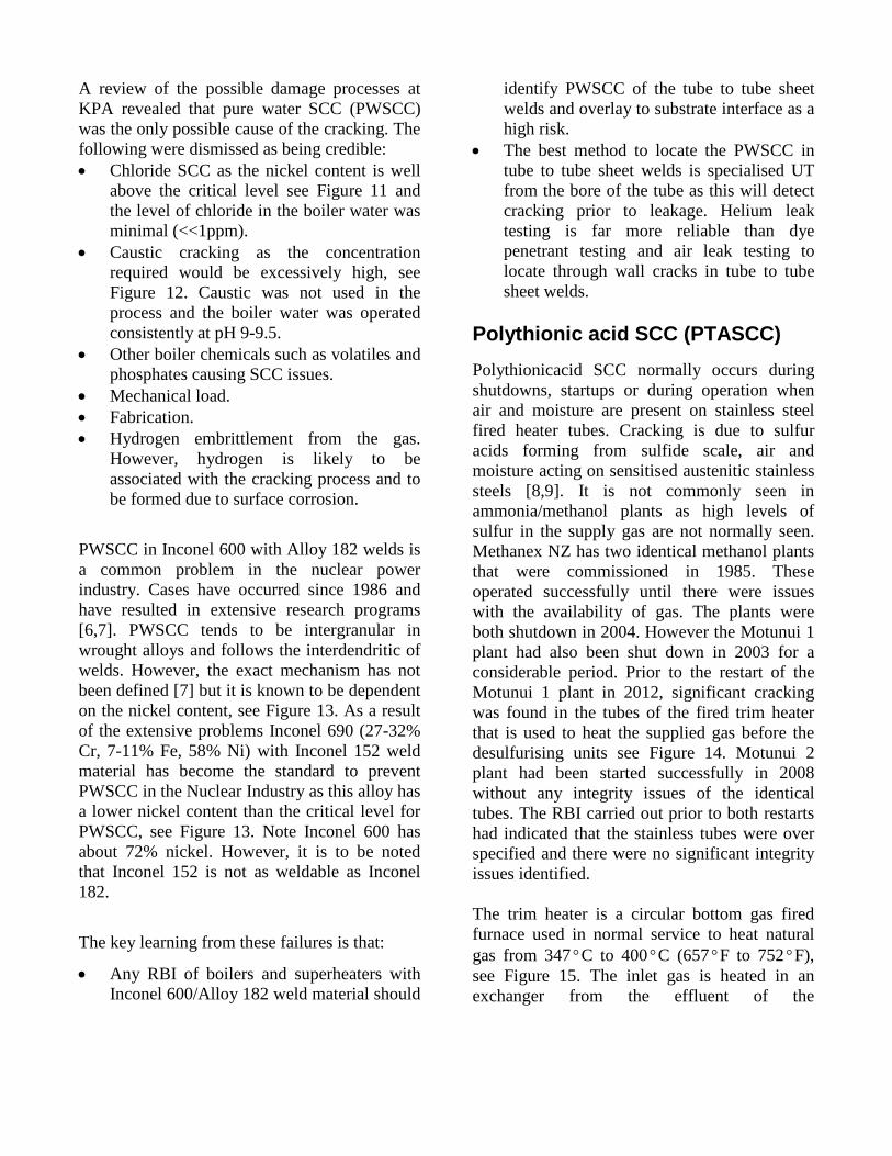
Polythionic acid SCC (PTASCC) Polythionicacid SCC normally occurs during shutdowns, startups or during operation when air and moisture are present on stainless steel fired heater tubes. Cracking is due to sulfur acids forming from sulfide scale, air and moisture acting on sensitised austenitic stainless steels [8,9]. It is not commonly seen in ammonia/methanol plants as high levels of sulfur in the supply gas are not normally seen. Methanex NZ has two identical methanol plants that were commissioned in 1985. These operated successfully until there were issues with the availability of gas. The plants were both shutdown in 2004. However the Motunui 1 plant had also been shut down in 2003 for a considerable period. Prior to the restart of the Motunui 1 plant in 2012, significant cracking was found in the tubes of the fired trim heater that is used to heat the supplied gas before the desulfurising units see Figure 14. Motunui 2 plant had been started successfully in 2008 without any integrity issues of the identical tubes. The RBI carried out prior to both restarts had indicated that the stainless tubes were over specified and there were no significant integrity issues identified. The trim heater is a circular bottom gas fired furnace used in normal service to heat natural gas from 347°C to 400°C (657°F to 752°F), see Figure 15. The inlet gas is heated in an exchanger from the effluent of the
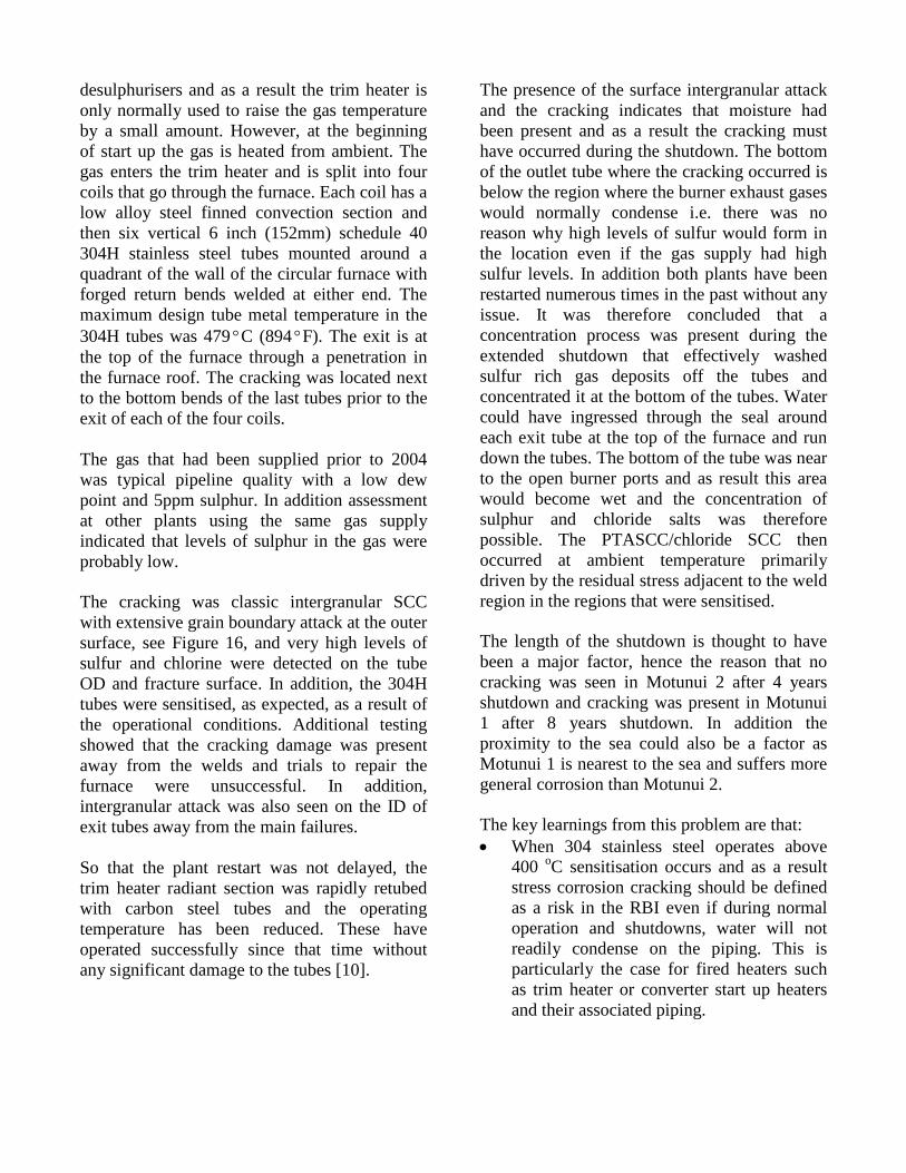
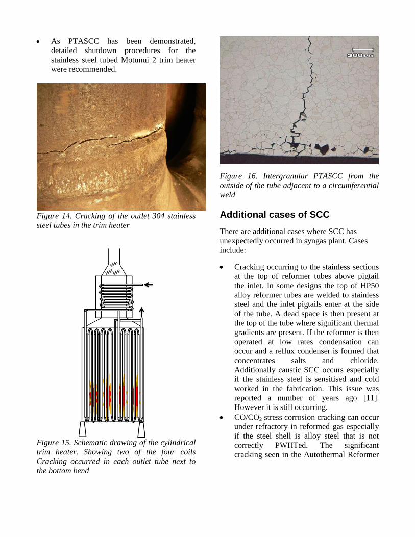
desulphurisers and as a result the trim heater is only normally used to raise the gas temperature by a small amount. However, at the beginning of start up the gas is heated from ambient. The gas enters the trim heater and is split into four coils that go through the furnace. Each coil has a low alloy steel finned convection section and then six vertical 6 inch (152mm) schedule 40 304H stainless steel tubes mounted around a quadrant of the wall of the circular furnace with forged return bends welded at either end. The maximum design tube metal temperature in the 304H tubes was 479°C (894°F). The exit is at the top of the furnace through a penetration in the furnace roof. The cracking was located next to the bottom bends of the last tubes prior to the exit of each of the four coils. The gas that had been supplied prior to 2004 was typical pipeline quality with a low dew point and 5ppm sulphur. In addition assessment at other plants using the same gas supply indicated that levels of sulphur in the gas were probably low. The cracking was classic intergranular SCC with extensive grain boundary attack at the outer surface, see Figure 16, and very high levels of sulfur and chlorine were detected on the tube OD and fracture surface. In addition, the 304H tubes were sensitised, as expected, as a result of the operational conditions. Additional testing showed that the cracking damage was present away from the welds and trials to repair the furnace were unsuccessful. In addition, intergranular attack was also seen on the ID of exit tubes away from the main failures. So that the plant restart was not delayed, the trim heater radiant section was rapidly retubed with carbon steel tubes and the operating temperature has been reduced. These have operated successfully since that time without any significant damage to the tubes [10].
The presence of the surface intergranular attack and the cracking indicates that moisture had been present and as a result the cracking must have occurred during the shutdown. The bottom of the outlet tube where the cracking occurred is below the region where the burner exhaust gases would normally condense i.e. there was no reason why high levels of sulfur would form in the location even if the gas supply had high sulfur levels. In addition both plants have been restarted numerous times in the past without any issue. It was therefore concluded that a concentration process was present during the extended shutdown that effectively washed sulfur rich gas deposits off the tubes and concentrated it at the bottom of the tubes. Water could have ingressed through the seal around each exit tube at the top of the furnace and run down the tubes. The bottom of the tube was near to the open burner ports and as result this area would become wet and the concentration of sulphur and chloride salts was therefore possible. The PTASCC/chloride SCC then occurred at ambient temperature primarily driven by the residual stress adjacent to the weld region in the regions that were sensitised. The length of the shutdown is thought to have been a major factor, hence the reason that no cracking was seen in Motunui 2 after 4 years shutdown and cracking was present in Motunui 1 after 8 years shutdown. In addition the proximity to the sea could also be a factor as Motunui 1 is nearest to the sea and suffers more general corrosion than Motunui 2. The key learnings from this problem are that: • When 304 stainless steel operates above
400 oC sensitisation occurs and as a result stress corrosion cracking should be defined as a risk in the RBI even if during normal operation and shutdowns, water will not readily condense on the piping. This is particularly the case for fired heaters such as trim heater or converter start up heaters and their associated piping.
• As PTASCC has been demonstrated, detailed shutdown procedures for the stainless steel tubed Motunui 2 trim heater were recommended.
Figure 14. Cracking of the outlet 304 stainless steel tubes in the trim heater
Figure 15. Schematic drawing of the cylindrical trim heater. Showing two of the four coils Cracking occurred in each outlet tube next to the bottom bend
Figure 16. Intergranular PTASCC from the outside of the tube adjacent to a circumferential weld
Additional cases of SCC There are additional cases where SCC has unexpectedly occurred in syngas plant. Cases include:
• Cracking occurring to the stainless sections at the top of reformer tubes above pigtail the inlet. In some designs the top of HP50 alloy reformer tubes are welded to stainless steel and the inlet pigtails enter at the side of the tube. A dead space is then present at the top of the tube where significant thermal gradients are present. If the reformer is then operated at low rates condensation can occur and a reflux condenser is formed that concentrates salts and chloride. Additionally caustic SCC occurs especially if the stainless steel is sensitised and cold worked in the fabrication. This issue was reported a number of years ago [11]. However it is still occurring.
• CO/CO2 stress corrosion cracking can occur under refractory in reformed gas especially if the steel shell is alloy steel that is not correctly PWHTed. The significant cracking seen in the Autothermal Reformer
in Methanex Trinidad is a classic example [12]
Discussions/Conclusions In each of the case studies provided, the cracking seen would not commonly be identified in an RBI program unless this is carried out by an experienced person who had significant knowledge of industrial issues. For example the PWSCC is not listed in documents such as API 571 [8] and the identification of the issue took considerable research to identify that this was a common problem in the nuclear power industry.
References 1. The British Health and Safety Executive
research report RR902. “Chloride stress corrosion cracking in austenitic stainless steels”
2. NACE MR0175/ISO 15156-1/2/3 Petroleum and natural gas industries – materials for use in H2 S containing environments in oil and gas production.
3. D M Firth, K A Lichti, Materials Performance Technologies, Lower Hutt, K Butler, Shell Todd Failure of High Strength Bolting Materials in an Offshore Platform Environment. Oil Services, New Plymouth. IMMA Conference Brisbane, April 1997.
4. H Pasaribu PT. Kaltim Pasifik Amoniak, Synloop Superheater Issues. AICHE 2008.
5. D M Firth et al MPT Solutions Cracking and repair of closing welds in 2.25 Cr1 Mo steel vessels operating in high temperature synthesis gas AICHE 2005.
6. U.S. Plant Experience with Alloy 600 Cracking and Boric Acid Corrosion of Light-Water Reactor Pressure Vessel Materials US nuclear Regulations commission publication March 2005.
7. Stress Corrosion Cracking in Light Water Reactors: Good Practices and
Lessons Learned, IAEA Nuclear Energy Series NP-T-3.13.
8. API 571 Damage mechanisms affecting fixed equipment in the refining industry. 2013.
9. NACE SP0170 2012 Standard Practice-Protection of Austenitic Stainless Steels and Other Austenitic Alloys from Polythionic Acid Stress Corrosion Cracking During a Shutdown of Refinery Equipment
10. Quest Integrity Metallurgical replication assessment of the fired heater 20-2-2014 confidential report.
11. B Cotton Johnson Matthey. Common Problems in Primary Reformers. AICHE 2004
12. D M Firth Quest Integrity. P Tait Methanex. Cracking of a Closing Weld in a Secondary Autothermal Reformer in a Mega Methanol Plant. AICHE 2011
13. H Pasaribu PT. Kaltim Pasifik Amoniak, Synloop Superheater Issues. AICHE 2008.