Embed Size (px)
Citation preview
Contents lists available at ScienceDirect
Journal of the Mechanical Behavior of Biomedical Materials
journal homepage: www.elsevier.com/locate/jmbbm
Stress corrosion cracking and corrosion fatigue characterisation ofMgZn1Ca0.3 (ZX10) in a simulated physiological environment
Sajjad Jafaria,⁎, R.K. Singh Ramana,b, Chris H.J. Daviesa, Joelle Hofstetterc, Peter J. Uggowitzerc,Jörg F. Löfflerc
a Department of Mechanical & Aerospace Engineering, Monash University (Melbourne), VIC 3800, Australiab Department of Chemical Engineering, Monash University (Melbourne), VIC 3800, Australiac Laboratory of Metal Physics and Technology, Department of Materials, ETH Zurich, 8093 Zurich, Switzerland
A R T I C L E I N F O
Keywords:Biodegradable implantsMagnesium alloysStress corrosion crackingCorrosion fatigueTwinning
A B S T R A C T
Magnesium (Mg) alloys have attracted great attention as potential materials for biodegradable implants. It isessential that an implant material possesses adequate resistance to cracking/fracture under the simultaneousactions of corrosion and mechanical stresses, i.e., stress corrosion cracking (SCC) and/or corrosion fatigue (CF).This study investigates the deformation behaviour of a newly developed high-strength low-alloy Mg alloy,MgZn1Ca0.3 (ZX10), processed at two different extrusion temperatures of 325 and 400 °C (named E325 andE400, respectively), under slow strain tensile and cyclic tension-compression loadings in air and modifiedsimulated body fluid (m-SBF). Extrusion resulted in a bimodal grain size distribution with recrystallised grainsizes of 1.2 μm ± 0.8 μm and 7 ± 5 μm for E325 and E400, respectively. E325 possessed superior tensile andfatigue properties to E400 when tested in air. This is mainly attributed to a grain-boundary strengtheningmechanism. However, both E325 and E400 were found to be susceptible to SCC at a strain rate of 3.1×10⁻⁷ s−1
in m-SBF. Moreover, both E325 and E400 showed similar fatigue strength when tested in m-SBF. This isexplained on the basis of crack initiation from localised corrosion following tests in m-SBF.
1. Introduction
Traditional implant materials, such as stainless steels, titaniumalloys and cobalt–chromium alloys, possess excellent load-bearingcapacity and resistance to wear, corrosion, and fatigue (Niinomiet al., 2012; Okazaki and Gotoh, 2008). However, when deployed astemporary implants, keeping them in the body beyond their recom-mended timeframe is disadvantageous, and removal surgery is re-quired after the healing process. This increases health care costs andinconvenience to patients. Using magnesium (Mg) alloys as potentialmaterials for temporary implants has recently attracted attention asthey are biodegradable and can dissolve completely in the body (Staigeret al., 2006; Witte, 2010). For such applications, Mg alloys must fulfilcertain electrochemical, biocompatibility and mechanical require-ments. Magnesium is biocompatible and essential to human metabo-lism with the added advantage of its biodegradable behaviour elim-inating the need for a second surgical procedure. It also possessesmechanical properties close to those of bone, reducing stress shieldingeffects under load-bearing conditions, which is a serious concern with
traditional alloys (Kraus et al., 2012; Saris et al., 2000; Witte et al.,2005). Despite these advantages, Mg alloys have rarely been used inbody implants. This is predominantly due to their rapid degradation inthe physiological environment, with unacceptably poor mechanicalintegrity before the bone has healed sufficiently (Kannan and Raman,2008; Song, 2007).
Implants in general are subjected to acute dynamic loadings duringnormal physical activities (Gu et al., 2010). Such loadings, along withthe corrosive physiological environment, pose the threat of stresscorrosion cracking (SCC) and corrosion fatigue (CF) (Antunes and deOliveira, 2012; Singh Raman et al., 2015). Several adverse incidentsinvolving the SCC and CF of traditional implants in the body environ-ment have been reported (Amel-Farzad et al., 2007; Sivakumar andRajeswari, 1992). Mg alloys are also susceptible to SCC and CF insimulated body fluids (SBF) (Choudhary and Raman, 2012; Choudharyet al., 2014; Gu et al., 2010; Jafari et al., 2015b). Therefore, it isimportant to identify Mg alloys that confer a combination of strengthand corrosion resistance in human body fluid without causing bodyfluid-assisted cracking such as SCC or CF. Due to the potential
http://dx.doi.org/10.1016/j.jmbbm.2016.09.033Received 23 May 2016; Received in revised form 15 September 2016; Accepted 27 September 2016
⁎ Correspondence to: Department of Mechanical & Aerospace Engineering, Department of Chemical Engineering, Bldg 37, Monash University – Clayton Campus (Melbourne), VIC3800, Australia.
E-mail address: [email protected] (S. Jafari).
Journal of the mechanical behavior of biomedical materials 65 (2017) 634–643
1751-6161/ Crown Copyright © 2016 Published by Elsevier Ltd. All rights reserved.Available online 28 September 2016
crossmark
neurotoxic effect of some alloying elements such as aluminium (Al),interest has been increasing in the development of Al-free Mg alloyscontaining only elements friendly to human biology (Gupta et al., 2005;Jafari et al., 2015a; Li et al., 2012; Witte et al., 2008). Different studiespointed out that elements such as calcium (Ca) and zinc (Zn) could beappropriate alloying element candidates for biomedical applicationsand demonstrated that Mg–Ca (Li et al., 2008) and Mg–Zn (Zhanget al., 2010) alloys gradually degraded and possessed good biocompat-ibility both in-vitro and in-vivo. In this context, Mg–Zn–Ca alloys (ZXseries) have displayed a good combination of mechanical propertiesand corrosion resistance (Hänzi et al., 2012; Liu et al., 2015; Sun et al.,2012). The mechanical properties of cast Mg–Zn–Ca alloys can beimproved through the hot extrusion process, with several researchersrecently demonstrating that extruded Mg–Zn–Ca alloys can be poten-tial candidates for biodegradable implant applications (Cha et al.,2013; Hofstetter et al., 2014; Liu et al., 2015). However, a specificallydesigned Mg alloy of this family for temporary implant applications,i.e., MgZn5Ca0.25 (ZX50), has been reported to suffer pitting corrosionin-vitro and rapid degradation in-vivo (Hofstetter et al., 2014).Moreover, this alloy has been shown to suffer SCC in modifiedsimulated body fluid (m-SBF) (Choudhary et al., 2014).
More recently, research on ZX alloys has resulted in the develop-ment of a high-strength low-alloy (HSLA) Mg alloy, MgZn1Ca0.3(ZX10), that exhibits slow and homogeneous degradation with nosignificant hydrogen bubble formation and excellent mechanical prop-erties (Hofstetter et al., 2014). This report indicates no evidence ofpitting after 2 weeks of immersion in Tris-buffered SBF, and slowdegradation in-vivo. This superior resistance to degradation is attrib-uted to the absence of noble intermetallic phases (IMPs) (Hofstetteret al., 2014). Most intermetallic phases that form in Mg alloys arecathodic to the primary phase with very few exceptions, such as Mg2Ca(Cha et al., 2013; Hofstetter et al., 2014; Südholz et al., 2011). Themain philosophy behind the development of the ZX10 alloy was to keepthe Zn and Ca contents to low enough levels in order to produce a veryfine dispersion of intermetallic particles that improve the strengthwhile minimising the localised dissolution/pitting due to the anodicnature of the intermetallics formed (Mg2Ca) (Hofstetter et al., 2014).However, there are no previous studies on the SCC and CF resistance ofZX10 in SBF.
This study investigates the SCC and CF behaviour of the ZX10 Mgalloy using slow strain rate tensile (SSRT) and fatigue (tension-compression; R=−1) testing in air and m-SBF. The effect of differentextrusion temperatures (325 and 400 °C) on subsequent deformationbehaviour of the ZX10 alloy under monotonic tensile and cyclicloadings in air and m-SBF is also examined.
2. Experimental procedure
2.1. Materials
Mg (99.95%) and the alloying elements (Ca (99.5%) and Zn(99.99%)) were melted at 750 °C in a graphite crucible (averagediameter 55 mm, height 150 mm) under a protective gas mixture(pure Ar with 1 vol.% of SF6). After adding the alloying elements themelt was stirred using a graphite stirrer at 300 rpm for 1 minute andthen held for 3 min. The melt was then poured into a graphite mouldwith water cooling at the base to avoid shrinkage cavities. The billetswere then homogenised and solutionised at 350 °C/12 h plus 480 °C/8 h, respectively, and cooled with pressurised air. The length of eachbillet prior to extrusion was 120 mm. The resulting billets weremachined to a diameter of 50 mm and aged at 250 °C for 30 min.Rods of 10 mm in diameter were then direct-extruded using anextrusion ratio of 25:1 and a ram speed of 0.5 mm/s. Extrusion wasperformed at two different temperatures (325 °C and 400 °C), with theresulting samples represented as E325 and E400, respectively. Thechemical analysis of the rods was performed by glow discharge mass
spectrometry, that determined the chemical compositions as given inTable 1.
2.2. Slow strain rate tensile (SSRT) testing in air and m-SBF
The SCC susceptibilities of E325 and E400 were investigated usingSSRT testing (ASTM G129, 2013) at a strain rate of 3.1×10⁻⁷ s−1 in airand m-SBF (see Table 2) at 37 °C. A schematic of the experimental set-up can be found elsewhere (Choudhary and Raman, 2012). Sampleswith 3 mm diameter and 20 mm gauge length were used for the SSRTtests. The gauge sections of the specimens were ground with SiC paperup to 2500 grit and then cleaned with ethanol prior to testing. SSRTtests were duplicated for each condition. In order to quantify the SCCsusceptibility, susceptibility indices of the Mg alloy were calculated asIUTS and IƐ, according to the following equations (where UTS repre-sents ultimate tensile strength and Ɛ represents elongation to failure)(Choudhary et al., 2014; Padekar et al., 2013):
I = (UTS in air)−(UTS in m−SBF)UTS in airUTS
and
I = (ε in air)−(ε in m−SBF)ε in air
.ε
When the value of the susceptibility index approaches zero, thematerial is taken to be highly resistant to SCC, i.e., the greater the indexthe greater the susceptibility to SCC.
2.3. Fatigue testing in air and m-SBF
Samples of 6 mm gauge diameter and 15 mm gauge length (ASTME466, 2004) were used for fatigue testing in air and m-SBF. After themachining process, the gauges of the specimens were ground with 1200and 2500 grit emery paper by running the paper in the loadingdirection and then polished with 1 μm diamond paste, followed bycleaning with ethanol. CF tests were carried out in m-SBF. An acryliccorrosion chamber was attached directly to the sample and m-SBF wascirculated through the chamber. The temperature of the solution wasmaintained at 37 °C using a water bath. All tests were performed at astress ratio of −1 (fully reversed) with a frequency of 10 Hz. Theexperimental setup has been described elsewhere (Jafari et al., 2015b).
Table 1Chemical compositions of the ZX10 rods (analysed by glow discharge mass spectrometry;Fe, Ni, Cu in wt.ppm, all other elements in wt%).
Alloy Zn Ca Al Si Mn Fe Ni Cu Mg
E325 0.96 0.20 0.022 0.027 0.033 29 9 12 Bal.E400 0.97 0.30 0.023 0.028 0.034 27 8 10 Bal.
Table 2Reagents and their quantities for preparation of 1000 ml of the m-SBF solution.
Reagents Amount
NaCl 5.403 gNaHCO3 0.504 gNa2CO3 0.426 gKCl 0.225 gK2HPO4.3H2O 0.23 gMgCl2.6H2O 0.311 g0.2 mol l-1 NaOH 100 mlHEPES 17.892 gCaCl2 0.293 gNa2SO4 0.072 g1 mol l-1 NaOH 15 ml
S. Jafari et al. Journal of the mechanical behavior of biomedical materials 65 (2017) 634–643
635
2.4. Fractography
The fracture surfaces of the specimens were examined usingscanning electron microscopy (SEM) after removal of corrosionproducts. Corrosion products were removed by immersion of samplesin a solution containing 20% CrO3 and 10% AgNO3 for about 3–5 s atroom temperature.
2.5. Electrochemical testing
The corrosion behaviour of the E325 and E400 alloys was studiedusing potentiodynamic polarisation. A conventional three-electrode cellwas deployed which consisted of a saturated calomel electrode (SCE) asthe reference electrode and a platinum mesh as the counter electrode.Polarisation scans were carried out in the m-SBF at a scan rate of 0.5mV/s after stabilisation of the open circuit potential for 2 h.
2.6. Texture measurements and electron backscatter diffraction(EBSD) analysis
Longitudinal sections parallel to the extrusion direction (ED) wereused for X-ray diffraction (XRD) macro-texture analysis. The bulktexture of the samples was determined using an MMA texturegoniometer and Cu anode radiation at 40 kV and 25 mA. Pole figureswere obtained for each plane up to a maximum tilt angle of 80° (phi)with a 5° interval.
Analysis of the micro-texture of the longitudinal section of thefractured specimens was performed using SEM (JEOL-7001F)equipped with an electron backscatter diffraction (EBSD) detector.For cross-sectional EBSD analysis of fatigue-fractured samples, thesamples were mounted before sectioning using epoxy to protect thefracture surface, then ground and polished to mirror finish using 2500grit paper and oxide polishing suspension (OPS) solution. A precision
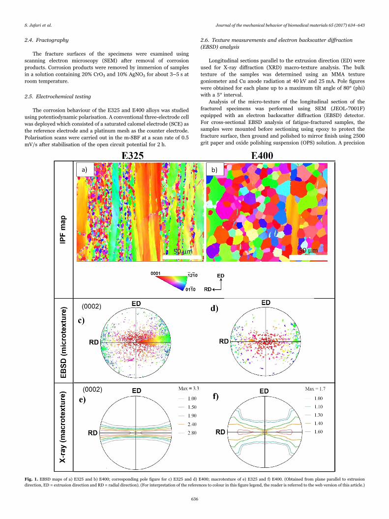
Fig. 1. EBSD maps of a) E325 and b) E400; corresponding pole figure for c) E325 and d) E400; macrotexture of e) E325 and f) E400. (Obtained from plane parallel to extrusiondirection, ED = extrusion direction and RD = radial direction). (For interpretation of the references to colour in this figure legend, the reader is referred to the web version of this article.)
S. Jafari et al. Journal of the mechanical behavior of biomedical materials 65 (2017) 634–643
636
etching and coating system (PECS) was then used at a tilting angle of75°, voltage of 7 kV, current of 385 μA, with etching time of 3–7 min tofurther improve the surface quality.
For EBSD characterisation, large area scans were collected using anaccelerating voltage of 20 keV, working distance of 10 mm, step size of0.2 µm and tilting angle of 70°. Scans were performed in such a waythat the extrusion direction (ED) was parallel to the instrument y-direction during the entire measurement. HKL Channel 5 software wasthen used to analyse the collected scans and to measure grain sizes.
3. Results
3.1. Microstructure and texture analysis
EBSD maps coloured according to the inverse pole figure (IPF)show that the alloys under both extrusion conditions (E325 and E400)possess a bimodal grain structure. E325 shows a high fraction ofunrecrystallised grains, with a grain size of 1.2 μm ± 0.8 μm in therecrystallised area (Fig. 1a), while E400 has a more homogenousmicrostructure with an average grain size of 7 μm ± 5 μm (Fig. 1b).There is good agreement between micro- and macro-textures, in whichthe texture of both E325 and E400 alloys proved to be typical of anextruded material with the c-axis distributed perpendicular to the ED.However, the E325 alloy shows higher texture intensity.
3.2. Slow strain rate tensile (SSRT) testing
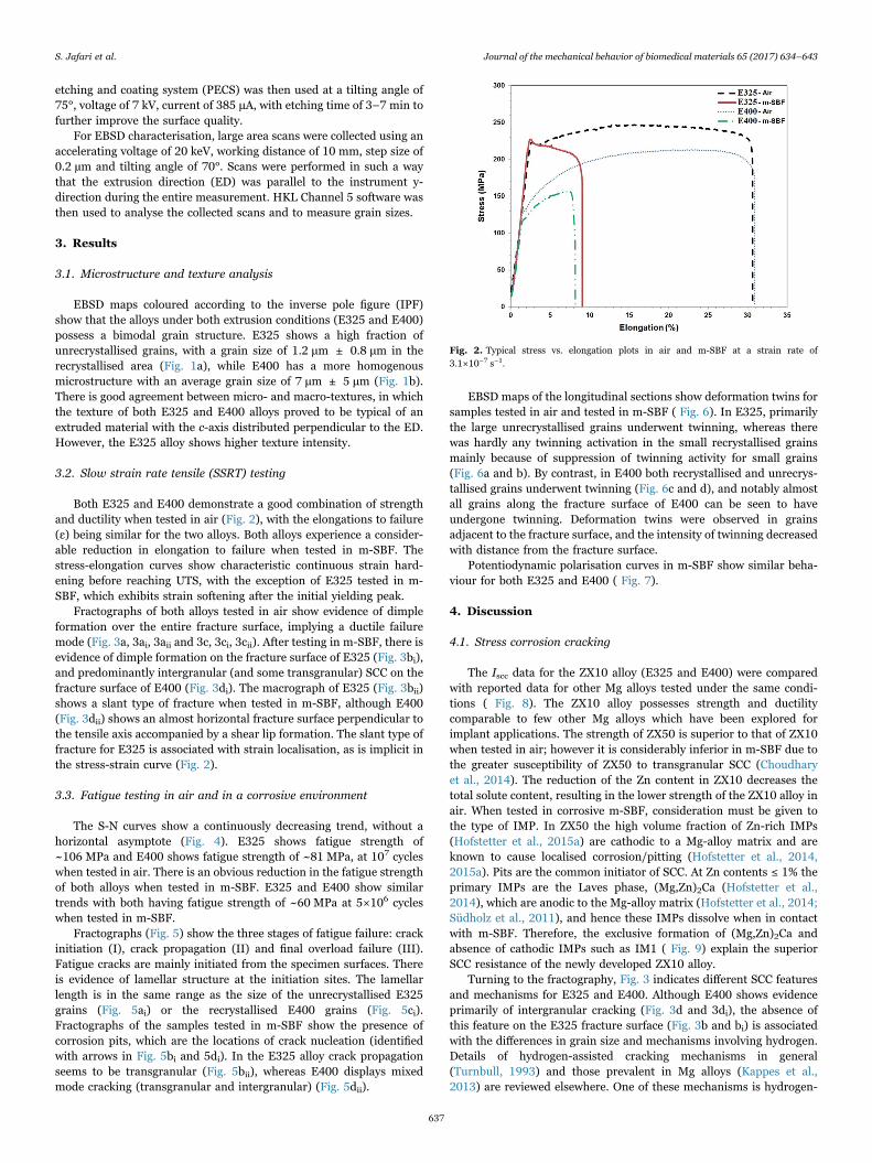
Both E325 and E400 demonstrate a good combination of strengthand ductility when tested in air (Fig. 2), with the elongations to failure(ε) being similar for the two alloys. Both alloys experience a consider-able reduction in elongation to failure when tested in m-SBF. Thestress-elongation curves show characteristic continuous strain hard-ening before reaching UTS, with the exception of E325 tested in m-SBF, which exhibits strain softening after the initial yielding peak.
Fractographs of both alloys tested in air show evidence of dimpleformation over the entire fracture surface, implying a ductile failuremode (Fig. 3a, 3ai, 3aii and 3c, 3ci, 3cii). After testing in m-SBF, there isevidence of dimple formation on the fracture surface of E325 (Fig. 3bi),and predominantly intergranular (and some transgranular) SCC on thefracture surface of E400 (Fig. 3di). The macrograph of E325 (Fig. 3bii)shows a slant type of fracture when tested in m-SBF, although E400(Fig. 3dii) shows an almost horizontal fracture surface perpendicular tothe tensile axis accompanied by a shear lip formation. The slant type offracture for E325 is associated with strain localisation, as is implicit inthe stress-strain curve (Fig. 2).
3.3. Fatigue testing in air and in a corrosive environment
The S-N curves show a continuously decreasing trend, without ahorizontal asymptote (Fig. 4). E325 shows fatigue strength of~106 MPa and E400 shows fatigue strength of ~81 MPa, at 107 cycleswhen tested in air. There is an obvious reduction in the fatigue strengthof both alloys when tested in m-SBF. E325 and E400 show similartrends with both having fatigue strength of ~60 MPa at 5×10⁶ cycleswhen tested in m-SBF.
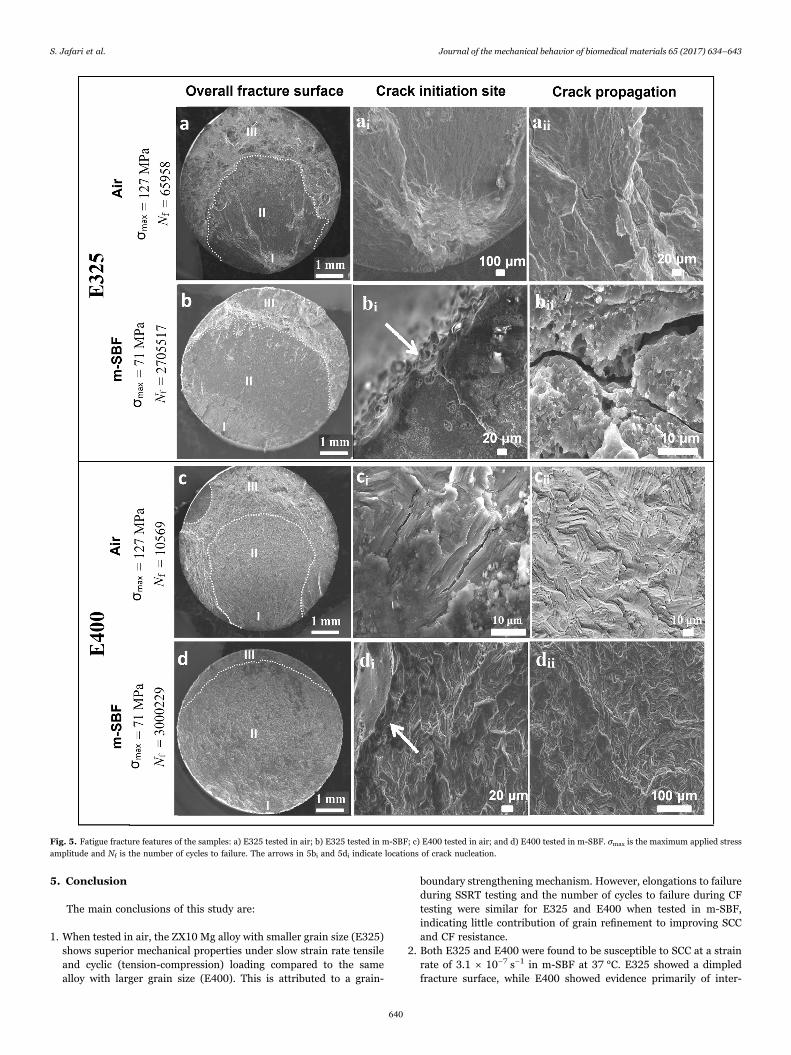
Fractographs (Fig. 5) show the three stages of fatigue failure: crackinitiation (I), crack propagation (II) and final overload failure (III).Fatigue cracks are mainly initiated from the specimen surfaces. Thereis evidence of lamellar structure at the initiation sites. The lamellarlength is in the same range as the size of the unrecrystallised E325grains (Fig. 5ai) or the recrystallised E400 grains (Fig. 5ci).Fractographs of the samples tested in m-SBF show the presence ofcorrosion pits, which are the locations of crack nucleation (identifiedwith arrows in Fig. 5bi and 5di). In the E325 alloy crack propagationseems to be transgranular (Fig. 5bii), whereas E400 displays mixedmode cracking (transgranular and intergranular) (Fig. 5dii).
EBSD maps of the longitudinal sections show deformation twins forsamples tested in air and tested in m-SBF ( Fig. 6). In E325, primarilythe large unrecrystallised grains underwent twinning, whereas therewas hardly any twinning activation in the small recrystallised grainsmainly because of suppression of twinning activity for small grains(Fig. 6a and b). By contrast, in E400 both recrystallised and unrecrys-tallised grains underwent twinning (Fig. 6c and d), and notably almostall grains along the fracture surface of E400 can be seen to haveundergone twinning. Deformation twins were observed in grainsadjacent to the fracture surface, and the intensity of twinning decreasedwith distance from the fracture surface.
Potentiodynamic polarisation curves in m-SBF show similar beha-viour for both E325 and E400 ( Fig. 7).
4. Discussion
4.1. Stress corrosion cracking
The Iscc data for the ZX10 alloy (E325 and E400) were comparedwith reported data for other Mg alloys tested under the same condi-tions ( Fig. 8). The ZX10 alloy possesses strength and ductilitycomparable to few other Mg alloys which have been explored forimplant applications. The strength of ZX50 is superior to that of ZX10when tested in air; however it is considerably inferior in m-SBF due tothe greater susceptibility of ZX50 to transgranular SCC (Choudharyet al., 2014). The reduction of the Zn content in ZX10 decreases thetotal solute content, resulting in the lower strength of the ZX10 alloy inair. When tested in corrosive m-SBF, consideration must be given tothe type of IMP. In ZX50 the high volume fraction of Zn-rich IMPs(Hofstetter et al., 2015a) are cathodic to a Mg-alloy matrix and areknown to cause localised corrosion/pitting (Hofstetter et al., 2014,2015a). Pits are the common initiator of SCC. At Zn contents ≤ 1% theprimary IMPs are the Laves phase, (Mg,Zn)2Ca (Hofstetter et al.,2014), which are anodic to the Mg-alloy matrix (Hofstetter et al., 2014;Südholz et al., 2011), and hence these IMPs dissolve when in contactwith m-SBF. Therefore, the exclusive formation of (Mg,Zn)2Ca andabsence of cathodic IMPs such as IM1 ( Fig. 9) explain the superiorSCC resistance of the newly developed ZX10 alloy.
Turning to the fractography, Fig. 3 indicates different SCC featuresand mechanisms for E325 and E400. Although E400 shows evidenceprimarily of intergranular cracking (Fig. 3d and 3di), the absence ofthis feature on the E325 fracture surface (Fig. 3b and bi) is associatedwith the differences in grain size and mechanisms involving hydrogen.Details of hydrogen-assisted cracking mechanisms in general(Turnbull, 1993) and those prevalent in Mg alloys (Kappes et al.,2013) are reviewed elsewhere. One of these mechanisms is hydrogen-
Fig. 2. Typical stress vs. elongation plots in air and m-SBF at a strain rate of3.1×10−7 s−1.
S. Jafari et al. Journal of the mechanical behavior of biomedical materials 65 (2017) 634–643
637
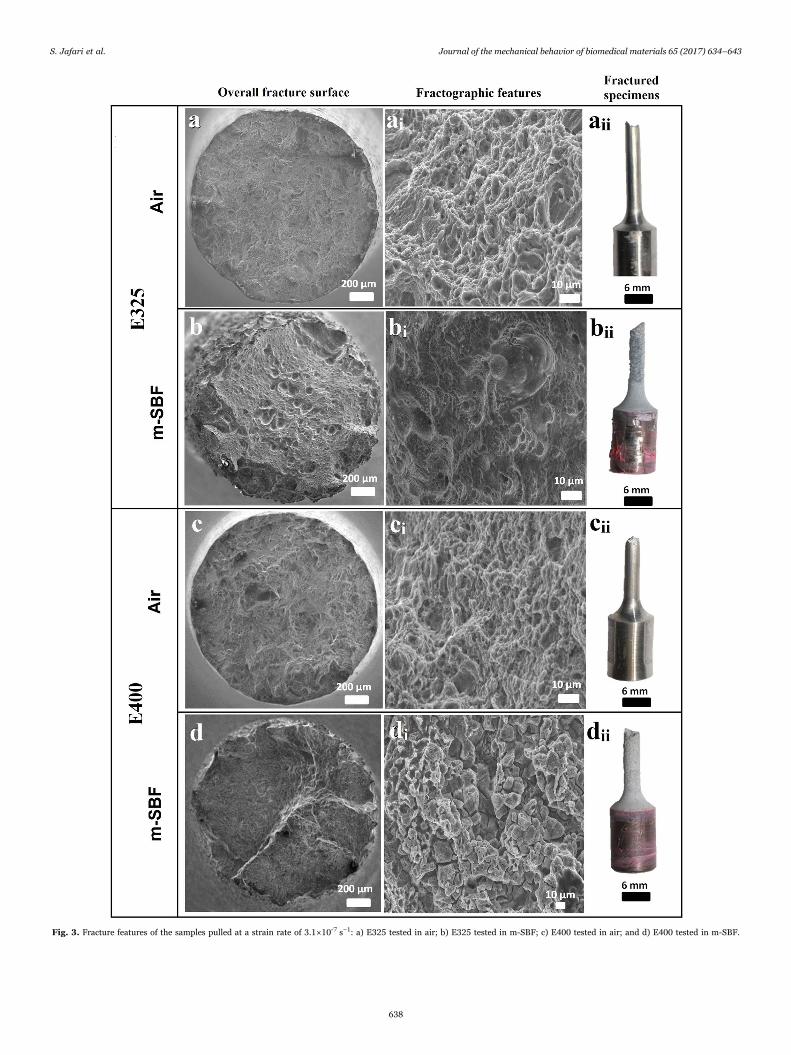
Fig. 3. Fracture features of the samples pulled at a strain rate of 3.1×10⁻⁷ s−1: a) E325 tested in air; b) E325 tested in m-SBF; c) E400 tested in air; and d) E400 tested in m-SBF.
S. Jafari et al. Journal of the mechanical behavior of biomedical materials 65 (2017) 634–643
638

enhanced localised plasticity (HELP), in which the dissolved hydrogenahead of the crack tip decreases the resistance to dislocation motion(the Peierls stress) (Kappes et al., 2013). Due to the localisation ofstress and hydrogen at the crack tip, plastic deformation is accom-panied by shear localisation at the crack tip, resulting in the slant-typefracture observed in Fig. 3bii. HELP has been shown to produce adimpled fracture surface (Kappes et al., 2013; Turnbull, 1993; Winzeret al., 2005) consistent with the observation for E325 (Fig. 3bi). This issupported by the flow stress reduction leading to strain localisation(Fig. 2), again in agreement with the literature (Birnbaum, 1983;Turnbull, 1993). Microstructural features such as grain boundaries andIMPs can affect the occurrence of SCC (Cao et al., 2015). Hydrogendiffusion through grain boundaries is expected to be higher (Cao et al.,2015) and therefore one of the main reasons for the contribution ofHELP to the SCC of E325 is attributable to the smaller grain size andconsequently greater grain-boundary area per unit volume of micro-structure. Cathodic IMPs can also act as hydrogen-trapping sitescontributing to SCC (Arnon and Aghion, 2008). The contribution ofanodic IMPs such as (Mg,Zn)2Ca to hydrogen-assisted cracking isunknown and requires further fundamental investigation.
E400, on the other hand, demonstrated greater SCC susceptibility(Fig. 8) with features primarily of intergranular SCC when tested in m-SBF (Fig. 3di). This is the result of a larger grain size in combinationwith hydrogen, which causes lowering of the surface energy at grainboundaries and subsequent intergranular cracking. On the basis of thepreceding discussions, the operative mechanism in which hydrogen isinvolved is different from that of E325.
4.2. Corrosion fatigue
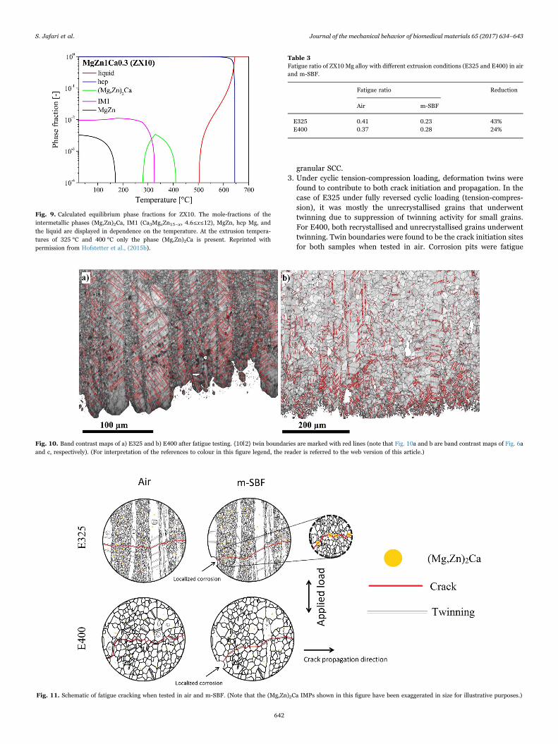
The basal texture of the E325 and E400 alloys causes a high fractionof grains to be oriented with their c-axes almost perpendicular to thedirection of applied load. As a result, there is a very high effectiveSchmid factor for tensile twinning activation in compression along theextrusion direction (ED). Demarcation of 86° ( ± 5°) boundaries alongthe rotation axis <1210 > confirms that the twins observed in Fig. 10are {1012} tensile twins. We expect the deformation behaviour of thealloys in response to cyclic loading to be profoundly influenced bytwinning. During cyclic loading the compressive load will result intensile twin formation and a subsequent tensile load may causedetwinning (Dong et al., 2014; Jiang et al., 2007; Liu et al., 2013).
The observed residual twins are the result of competition betweentwinning in compression and detwinning in tension during the cyclicdeformation. Twinning-detwinning during cyclic tension-compressionhas also been observed for other wrought Mg alloys in whichdeformation twins are reported to contribute to both fatigue crackinitiation and propagation (Koike et al., 2010; Liu et al., 2013). SEMimages and EBSD maps (Figs. 5 and 6) confirm the role of deformation
twins in crack initiation and propagation. The direct evidence for this isthe occurrence of twin-like features at the crack initiation sites of mostsamples when tested in air (Fig. 5). During cyclic loading the localstrain concentration is relatively high at twin bands and therefore theycan act as fatigue crack initiation sites, consistent with other reports(Bernard et al., 2010; Yang et al., 2011). A recent study suggests thatthe twin boundaries are intrinsically brittle and can act as damageinitiation sites (Wu and Curtin, 2015). The observation of twins alongthe fracture surface (Fig. 6) and facets on the surface which have aninclination towards the extrusion direction similar to that of twins(Fig. 6) provides further evidence of such a scenario. This observationsuggests that as the cracks propagate twinning ahead of the crack tipprovide a potential path for crack propagation in E400 for grains with afavourable orientation towards twinning activation.
In order to evaluate the fatigue properties of the two alloys, theratio of fatigue strength to the UTS in air and m-SBF was compared(higher ratio demonstrates superior resistance to fatigue). ThoughE325 shows fatigue resistance superior to that of E400 in air, its fatigueratio is lower when tested in m-SBF, indicating somewhat greatersusceptibility to CF cracking (Table 3). However, the greater suscept-ibility of E325 cannot be attributed to electrochemical factors, given thealmost identical electrochemical polarisation behaviour of E325 andE400 respectively (Fig. 7).
In fact, the greater susceptibility of E325 to CF in m-SBF could beexplained on the basis of crack initiation and the growth of shortfatigue cracks ( Fig. 11). In the case of E325, although cracks initiatedat the twin boundaries of unrecrystallised grains, the short fatiguecracks encountered a higher fraction of microstructural barriers suchas grain boundaries and IMPs, and hence the growth of the shortfatigue cracks is expected to be slow. In contrast, E400 demonstratedthat the short fatigue cracks have a much easier path for growth, withextensive twinning ahead of the crack tip providing a preferential pathfor cracking. Therefore, the superior fatigue performance of E325 whentested in air can be attributed to longer initiation life and slow growthof short fatigue cracks. This is consistent with the literature, where anincrease in fatigue strength with decreasing grain size is attributed tocrack initiation and short fatigue crack growth resistance (Uematsuet al., 2006).
When tested in m-SBF, the fatigue crack initiation phase isaccelerated due to localised corrosion. Furthermore, dissolution ofanodic IMPs such as (Mg,Zn)2Ca can be deleterious to CF resistancedue to their role in accelerating short fatigue crack growth by providingan easy path for crack propagation. This phenomenon is moreprominent in E325 because of its higher volume fraction of(Mg,Zn)2Ca IMPs (Fig. 9). It has been experimentally validated thatE325 has a higher volume fraction of (Mg,Zn)2Ca IMPs compared tothat of E400 (Hofstetter et al., 2015b). The role of the volume fractionof intermetallic particles is presumably a secondary but still unresolvedfactor.
Orthopaedic implants need to maintain their mechanical integrityfor about 5×10⁵ cycles (Gu et al., 2010; Jafari et al., 2015b). Thefindings of this study show that the ZX10 alloy possesses a fatiguestrength of 78 MPa in m-SBF at 5×10⁵ cycles, higher than the requiredphysiological strength (20.4–25.5 MPa) and bone fatigue strength (23–30 MPa) (Gu et al., 2010). This may suggest that this alloy hassufficient CF resistance for implant applications. However, it must benoted that implants in the body can experience complex and multi-axial loading including bending, torsion, compression, tension andtheir combinations (Bundy and Zardiackas, 2006), whereas the CF testemployed in this study was a simple constant-amplitude tension-compression loading. Moreover, the frequency of loading for ortho-paedic implants is lower (1–3 Hz) (Singh Raman et al., 2015).Therefore, future research should also require CF tests under a loadingspectrum that simulates actual body conditions.
Fig. 4. S-N curves for E325 and E400 alloys tested in air and m-SBF (arrows correspondto run-out samples).
S. Jafari et al. Journal of the mechanical behavior of biomedical materials 65 (2017) 634–643
639
5. Conclusion
The main conclusions of this study are:
1. When tested in air, the ZX10 Mg alloy with smaller grain size (E325)shows superior mechanical properties under slow strain rate tensileand cyclic (tension-compression) loading compared to the samealloy with larger grain size (E400). This is attributed to a grain-
boundary strengthening mechanism. However, elongations to failureduring SSRT testing and the number of cycles to failure during CFtesting were similar for E325 and E400 when tested in m-SBF,indicating little contribution of grain refinement to improving SCCand CF resistance.
2. Both E325 and E400 were found to be susceptible to SCC at a strainrate of 3.1 × 10⁻⁷ s−1 in m-SBF at 37 °C. E325 showed a dimpledfracture surface, while E400 showed evidence primarily of inter-
Fig. 5. Fatigue fracture features of the samples: a) E325 tested in air; b) E325 tested in m-SBF; c) E400 tested in air; and d) E400 tested in m-SBF. σmax is the maximum applied stressamplitude and Nf is the number of cycles to failure. The arrows in 5bi and 5di indicate locations of crack nucleation.
S. Jafari et al. Journal of the mechanical behavior of biomedical materials 65 (2017) 634–643
640
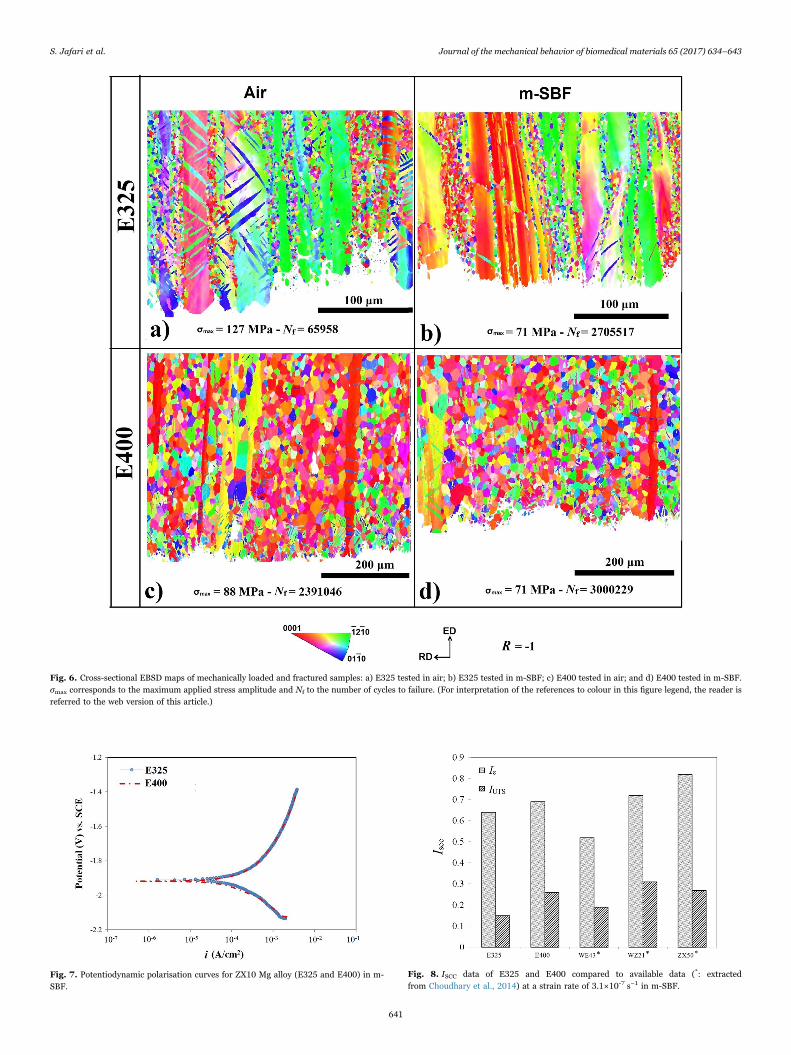
Fig. 6. Cross-sectional EBSD maps of mechanically loaded and fractured samples: a) E325 tested in air; b) E325 tested in m-SBF; c) E400 tested in air; and d) E400 tested in m-SBF.σmax corresponds to the maximum applied stress amplitude and Nf to the number of cycles to failure. (For interpretation of the references to colour in this figure legend, the reader isreferred to the web version of this article.)
Fig. 7. Potentiodynamic polarisation curves for ZX10 Mg alloy (E325 and E400) in m-SBF.
Fig. 8. ISCC data of E325 and E400 compared to available data (*: extractedfrom Choudhary et al., 2014) at a strain rate of 3.1×10⁻⁷ s−1 in m-SBF.
S. Jafari et al. Journal of the mechanical behavior of biomedical materials 65 (2017) 634–643
641
granular SCC.3. Under cyclic tension-compression loading, deformation twins were
found to contribute to both crack initiation and propagation. In thecase of E325 under fully reversed cyclic loading (tension-compres-sion), it was mostly the unrecrystallised grains that underwenttwinning due to suppression of twinning activity for small grains.For E400, both recrystallised and unrecrystallised grains underwenttwinning. Twin boundaries were found to be the crack initiation sitesfor both samples when tested in air. Corrosion pits were fatigue
Fig. 9. Calculated equilibrium phase fractions for ZX10. The mole-fractions of theintermetallic phases (Mg,Zn)2Ca, IM1 (Ca3MgxZn15−x, 4.6≤x≤12), MgZn, hcp Mg, andthe liquid are displayed in dependence on the temperature. At the extrusion tempera-tures of 325 °C and 400 °C only the phase (Mg,Zn)2Ca is present. Reprinted withpermission from Hofstetter et al., (2015b).
Fig. 10. Band contrast maps of a) E325 and b) E400 after fatigue testing. {1012} twin boundaries are marked with red lines (note that Fig. 10a and b are band contrast maps of Fig. 6aand c, respectively). (For interpretation of the references to colour in this figure legend, the reader is referred to the web version of this article.)
Table 3Fatigue ratio of ZX10 Mg alloy with different extrusion conditions (E325 and E400) in airand m-SBF.
Fatigue ratio Reduction
Air m-SBF
E325 0.41 0.23 43%E400 0.37 0.28 24%
Fig. 11. Schematic of fatigue cracking when tested in air and m-SBF. (Note that the (Mg,Zn)2Ca IMPs shown in this figure have been exaggerated in size for illustrative purposes.)
S. Jafari et al. Journal of the mechanical behavior of biomedical materials 65 (2017) 634–643
642
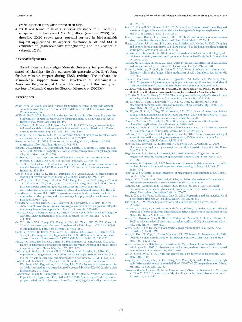
crack initiation sites when tested in m-SBF.4. ZX10 was found to have a superior resistance to CF and SCC
compared to other recent ZX Mg alloys (such as ZX50), andtherefore ZX10 shows great potential for use in biodegradableimplant applications. Its superior resistance to CF and SCC isattributed to grain-boundary strengthening and the absence ofcathodic IMPs.
Acknowledgments
Sajjad Jafari acknowledges Monash University for providing re-search scholarships. He also expresses his gratitude to Dr. Xi-Ya Fangfor her valuable support during EBSD training. The authors alsoacknowledge support from the Department of Mechanical &Aerospace Engineering at Monash University, and the facility andservices of Monash Centre for Electron Microscopy (MCEM).
References
ASTM-E466-96, 2004. Standard Practice for Conducting Force Controlled ConstantAmplitude Axial Fatigue Tests of Metallic Materials. ASTM International, WestConshohocken, PA.
ASTM G129-00, 2013. Standard Practice for Slow Strain Rate Testing to Evaluate theSusceptibility of Metallic Materials to Environmentally Assisted Cracking. ASTMInternational, West Conshohocken, PA.
Amel-Farzad, H., Peivandi, M.T., Yusof-Sani, S.M.R., 2007. In-body corrosion fatiguefailure of a stainless steel orthopaedic implant with a rare collection of differentdamage mechanisms. Eng. Fail. Anal. 14, 1205–1217.
Antunes, R.A., de Oliveira, M.C., 2012. Corrosion fatigue of biomedical metallic alloys:mechanisms and mitigation. Acta Biomater. 8, 937–962.
Arnon, A., Aghion, E., 2008. Stress corrosion cracking of nano/sub-micron E906magnesium alloy. Adv. Eng. Mater. 10, 742–745.
Bernard, J.D., Jordon, J.B., Horstemeyer, M.F., Kadiri, H.E., Baird, J., Lamb, D., Luo,A.A., 2010. Structure–property relations of cyclic damage in a wrought magnesiumalloy. Scr. Mater. 63, 751–756.
Birnbaum, H.K., 1983. Hydrogen related fracture of metals. In: Latanision, R.M.,Pickens, J.R. (Eds.), Atomistics of Fracture. Springer, US, 733–769.
Bundy, K.J., Zardiackas, L.D., 2006. Corrosion fatigue and stress-corrosion cracking inmetallic biomaterialsASM Handbook Vol. 13C, Corrosion: Environments andIndustries, 853–890.
Cao, F., Shi, Z., Song, G.-L., Liu, M., Dargusch, M.S., Atrens, A., 2015. Stress corrosioncracking of several hot-rolled binary Mg-X alloys. Corros. Sci. 98, 6–19.
Cha, P.-R., Han, H.-S., Yang, G.-F., Kim, Y.-C., Hong, K.-H., Lee, S.-C., Jung, J.-Y., Ahn,J.-P., Kim, Y.-Y., Cho, S.-Y., Byun, J.Y., Lee, K.-S., Yang, S.-J., Seok, H.-K., 2013.Biodegradability engineering of biodegradable Mg alloys: Tailoring theelectrochemical properties and microstructure of constituent phases. Sci. Rep., 3.
Choudhary, L., Raman, R.K., 2012. Magnesium alloys as body implants: fracturemechanism under dynamic and static loadings in a physiological environment. ActaBiomater. 8, 916–923.
Choudhary, L., Singh Raman, R.K., Hofstetter, J., Uggowitzer, P.J., 2014. In-vitrocharacterization of stress corrosion cracking of aluminium-free magnesium alloys fortemporary bio-implant applications. Mater. Sci. Eng. 42, 629–636.
Dong, S., Jiang, Y., Dong, J., Wang, F., Ding, W., 2014. Cyclic deformation and fatigue ofextruded ZK60 magnesium alloy with aging effects. Mater. Sci. Eng. , A 615,262–272.
Gu, X.N., Zhou, W.R., Zheng, Y.F., Cheng, Y., Wei, S.C., Zhong, S.P., Xi, T.F., Chen, L.J.,2010. Corrosion fatigue behaviors of two biomedical Mg alloys – AZ91D and WE43 –in simulated body fluid. Acta Biomater. 6, 4605–4613.
Gupta, V., Anitha, S., Hegde, M.L., Zecca, L., Garruto, R.M., Ravid, R., Shankar, S.K.,Stein, R., Shanmugavelu, P., Jagannatha Rao, K.S., 2005. Aluminium in Alzheimer'sdisease: are we still at a crossroad? CMLS Cell. Mol. Life Sci. 62, 143–158.
Hänzi, A.C., Sologubenko, A.S., Gunde, P., Schinhammer, M., Uggowitzer, P.J., 2012.Design considerations for achieving simultaneously high-strength and highly ductilemagnesium alloys. Philos. Mag. Lett. 92, 417–427.
Hofstetter, J., Becker, M., Martinelli, E., Weinberg, A.M., Mingler, B., Kilian, H.,Pogatscher, S., Uggowitzer, P.J., Löffler, J.F., 2014. High-strength low-alloy (HSLA)Mg–Zn–Ca alloys with excellent biodegradation performance. JOM 66, 566–572.
Hofstetter, J., Martinelli, E., Pogatscher, S., Schmutz, P., Povoden-Karadeniz, E.,Weinberg, A.M., Uggowitzer, P.J., Löffler, J.F., 2015a. Influence of trace impuritieson the in vitro and in vivo degradation of biodegradable Mg–5Zn–0.3Ca alloys. ActaBiomater. 23, 347–353.
Hofstetter, J., Rüedi, S., Baumgartner, I., Kilian, H., Mingler, B., Povoden-Karadeniz, E.,Pogatscher, S., Uggowitzer, P.J., Löffler, J.F., 2015b. Processing and microstructure–property relations of high-strength low-alloy (HSLA) Mg–Zn–Ca alloys. Acta Mater.
98, 423–432.Jafari, S., Harandi, S.E., Raman, R.K.S., 2015a. A review of stress corrosion cracking and
corrosion fatigue of magnesium alloys for biodegradable implant applications. J.Miner. Met. Mater. Soc. 67, 1143–1153.
Jafari, S., Singh Raman, R.K., Davies, C.H.J., 2015b. Corrosion fatigue of a magnesiumalloy in modified simulated body fluid. Eng. Fract. Mech. 137, 2–11.
Jiang, L., Jonas, J.J., Mishra, R.K., Luo, A.A., Sachdev, A.K., Godet, S., 2007. Twinningand texture development in two Mg alloys subjected to loading along three differentstrain paths. Acta Mater. 55, 3899–3910.
Kannan, M.B., Raman, R.K.S., 2008. In vitro degradation and mechanical integrity ofcalcium-containing magnesium alloys in modified-simulated body fluid. Biomaterials29, 2306–2314.
Kappes, M., Iannuzzi, M., Carranza, R.M., 2013. Hydrogen embrittlement of magnesiumand magnesium alloys: a review. J. Electrochem. Soc. 160, C168–C178.
Koike, J., Fujiyama, N., Ando, D., Sutou, Y., 2010. Roles of deformation twinning anddislocation slip in the fatigue failure mechanism of AZ31 Mg alloys. Scr. Mater. 63,747–750.
Kraus, T., Fischerauer, S.F., Hänzi, A.C., Uggowitzer, P.J., Löffler, J.F., Weinberg, A.M.,2012. Magnesium alloys for temporary implants in osteosynthesis: in vivo studies oftheir degradation and interaction with bone. Acta Biomater. 8, 1230–1238.
Y., Li, C., Wen, D., Mushahary, R., Sravanthi, N., Harishankar, G., Pande, P., Hodgson,2012. Mg-Zr-Sr alloys as biodegradable implant materials. Acta Biomater.
Li, Z., Gu, X., Lou, S., Zheng, Y., 2008. The development of binary Mg–Ca alloys for useas biodegradable materials within bone. Biomaterials 29, 1329–1344.
Liu, D., Guo, C., Chai, L., Sherman, V.R., Qin, X., Ding, Y., Meyers, M.A., 2015.Mechanical properties and corrosion resistance of hot extruded Mg–2.5Zn–1Caalloy. Mater. Sci. Eng.: B 195, 50–58.
Liu, W., Wu, G., Zhai, C., Ding, W., Korsunsky, A.M., 2013. Grain refinement and fatiguestrengthening mechanisms in as-extruded Mg–6Zn–0.5Zr and Mg–10Gd–3Y–0.5Zrmagnesium alloys by shot peening. Int. J. Plast. 49, 16–35.
Niinomi, M., Nakai, M., Hieda, J., 2012. Development of new metallic alloys forbiomedical applications. Acta Biomater. 8, 3888–3903.
Okazaki, Y., Gotoh, E., 2008. Metal release from stainless steel, Co–Cr–Mo–Ni–Fe andNi–Ti alloys in vascular implants. Corros. Sci. 50, 3429–3438.
Padekar, B.S., Singh Raman, R.K., Raja, V.S., Paul, L., 2013. Stress corrosion cracking ofa recent rare-earth containing magnesium alloy, EV31A, and a common Al-containing alloy, AZ91E. Corros. Sci. 71, 1–9.
Saris, N.-E.L., Mervaala, E., Karppanen, H., Khawaja, J.A., Lewenstam, A., 2000.Magnesium: an update on physiological, clinical and analytical aspects. Clin. Chim.Acta 294, 1–26.
Singh Raman, R.K., Jafari, S., Harandi, S.E., 2015. Corrosion fatigue fracture ofmagnesium alloys in bioimplant applications: a review. Eng. Fract. Mech. 137,97–108.
Sivakumar, M., Rajeswari, S., 1992. Investigation of failures in stainless steel orthopaedicimplant devices: pit-induced stress corrosion cracking. J. Mater. Sci. Lett. 11,1039–1042.
Song, G., 2007. Control of biodegradation of biocompatable magnesium alloys. Corros.Sci. 49, 1696–1701.
Staiger, M.P., Pietak, A.M., Huadmai, J., Dias, G., 2006. Magnesium and its alloys asorthopedic biomaterials: a review. Biomaterials 27, 1728–1734.
Südholz, A.D., Kirkland, N.T., Buchheit, R.G., Birbilis, N., 2011. Electrochemicalproperties of intermetallic phases and common impurity elements in magnesiumalloys. Electrochem. Solid-State Lett. 14, C5–C7.
Sun, Y., Zhang, B., Wang, Y., Geng, L., Jiao, X., 2012. Preparation and characterization ofa new biomedical Mg–Zn–Ca alloy. Mater. Des. 34, 58–64.
Turnbull, A., 1993. Modelling of environment assisted cracking. Corros. Sci. 34,921–960.
Uematsu, Y., Tokaji, K., Kamakura, M., Uchida, K., Shibata, H., Bekku, N., 2006. Effect ofextrusion conditions on grain refinement and fatigue behaviour in magnesium alloys.Mater. Sci. Eng. , A 434, 131–140.
Winzer, N., Atrens, A., Song, G., Ghali, E., Dietzel, W., Kainer, K.U., Hort, N., Blawert, C.,2005. A critical review of the stress corrosion cracking (SCC) of magnesium alloys.Adv. Eng. Mater. 7, 659–693.
Witte, F., 2010. The history of biodegradable magnesium implants: a review. ActaBiomater. 6, 1680–1692.
Witte, F., Hort, N., Vogt, C., Cohen, S., Kainer, K.U., Willumeit, R., Feyerabend, F., 2008.Degradable biomaterials based on magnesium corrosion. Curr. Opin. Solid StateMater. Sci. 12, 63–72.
Witte, F., Kaese, V., Haferkamp, H., Switzer, E., Meyer-Lindenberg, A., Wirth, C.J.,Windhagen, H., 2005. In vivo corrosion of four magnesium alloys and the associatedbone response. Biomaterials 26, 3557–3563.
Wu, Z., Curtin, W.A., 2015. Brittle and ductile crack-tip behavior in magnesium. ActaMater. 88, 1–12.
Yang, F., Lv, F., Yang, X.M., Li, S.X., Zhang, Z.F., Wang, Q.D., 2011. Enhanced very highcycle fatigue performance of extruded Mg–12Gd–3Y–0.5Zr magnesium alloy. Mater.Sci. Eng. , A 528, 2231–2238.
Zhang, S., Zhang, X., Zhao, C., Li, J., Song, Y., Xie, C., Tao, H., Zhang, Y., He, Y., Jiang,Y., Bian, Y., 2010. Research on an Mg–Zn alloy as a degradable biomaterial. ActaBiomater. 6, 626–640.
S. Jafari et al. Journal of the mechanical behavior of biomedical materials 65 (2017) 634–643
643