Embed Size (px)
Citation preview
Strength degradation mechanisms in NiAl alloy coated sapphire fibers
Von der Fakultät für Georessourcen und Materialtechnik der Rheinisch-Westfälischen Technischen Hochschule Aachen
zur Erlangung des akademischen Grades eines
Doktors der Naturwissenschaften
genehmigte Dissertation
vorgelegt von Master of Science (Physik)
David Edward Hajas
aus Jönköping, Schweden
Berichter: Univ.-Prof. Jochen M. Schneider, Ph.D. Univ.-Prof. Dr.-Ing. Christoph Leyens
Tag der mündlichen Prüfung: 01. Februar 2008
Diese Dissertation ist auf den Internetseiten der Hochschulbibliothek online verfügbar

Shaker VerlagAachen 2008
Materials Chemistry Dissertation
No.: 08 (2008)
David E. Hajas
Strength degradation mechanismsin NiAl alloy coated sapphire fibers
Bibliographic information published by the Deutsche NationalbibliothekThe Deutsche Nationalbibliothek lists this publication in the DeutscheNationalbibliografie; detailed bibliographic data are available in the Internet athttp://dnb.d-nb.de.
Zugl.: Aachen, Techn. Hochsch., Diss., 2008
Copyright Shaker Verlag 2008All rights reserved. No part of this publication may be reproduced, stored in aretrieval system, or transmitted, in any form or by any means, electronic,mechanical, photocopying, recording or otherwise, without the prior permissionof the publishers.
Printed in Germany.
ISBN 978-3-8322-7471-9ISSN 1861-0595
Shaker Verlag GmbH • P.O. BOX 101818 • D-52018 AachenPhone: 0049/2407/9596-0 • Telefax: 0049/2407/9596-9Internet: www.shaker.de • e-mail: [email protected]
iii
Abstract
The efficiency of a gas turbine can be increased by increasing the
combustion zone temperature. For this new materials are needed. NiAl
strengthened with single crystal �-Al2O3 (sapphire) fibers is considered as
a load bearing component in the combustion zone turbine blades.
However, due to strength degradation of the fibers during composite
fabrication, sufficient strengthening of NiAl can not be achieved. The goal
of this thesis is to identify strength degradation relevant mechanisms in
order to minimize the strength degradation during the production of
Intermetallc Matrix Composites (IMC’s) in the future. NiAl and IP75
(Ni45Al45Cr7,5Ta2,5) were considered as matrix materials. The presence of
an interlayer on the fiber strength was studied; hexagonal BN (h-BN) for a
weak interface, Y and Hf for enhanced interface strength by compound
formation. The strength of coated fibers was evaluated by tensile testing
and compared to the strength of uncoated fibers. The effect of temperature
during diffusion bonding was studied. None of the investigated coupling
concepts yields the improvement in tensile strength of NiAl or IP75
necessary for high temperature structural applications due to process
related fiber strength degradation.
iv
By systematic examination of fracture and fiber surfaces as well as
chemical analysis, the following strength degradation mechanisms have
been identified: Twinning of the rhombohedral plane (r-plane) of the
sapphire crystal as a consequence of the evolving thermal stress during
cooling. Chemical reactions between fiber and matrix material and/or
impurities and surface diffusion of Al2O3 into irregularities in the adjacent
matrix material like cracks in the h-BN interlayer both lead to altering of the
fiber surface morphology. In combination with the evolving thermal stress
during cooling, fracture mirror formation at the surface flaws takes place,
degrading the fiber strength.
In this work the fiber strength degradation mechanisms active during
individual process steps are identified. The significance of thermal stress
induced fiber damage is emphasized and it is concluded that the
elimination or a significant reduction thereof is the largest challenge which
has to be addressed to explore the strengthening potential of sapphire
fibers for IMC´s in the future.
Based on the results presented here, a strategy for obtaining high
strength IMC´s in the future is compiled. It is suggested that the strength
degradation may be avoided or minimized by: lowering the thermal stress
by increasing the fiber volume fraction and/or by using a ductile interlayer.
v
Zusammenfassung
Der Wirkungsgrad einer Gasturbine kann durch eine Erhöhung der
Brennkammertemperatur gesteigert werden. Dazu werden neuartige
Hochtemperaturwerkstoffe benötigt. Langfaserverstärktes NiAl mit
einkristallinen �-Al2O3-Fasern (Saphir) soll die lasttragende Komponente in
der Brennkammerturbinenschaufel darstellen. Aufgrund von
Festigkeitserniedrigungen der Saphirfaser kann jedoch keine ausreichende
Verstärkung des NiAl erreicht werden. Das Ziel dieser Arbeit ist es, die
relevanten Festigkeitserniedrigungsmechanismen zu identifizieren, um
zukünftig die Festigkeitserniedrigung während der Herstellung des
intermetallischen Komposites zu minimieren. Als Matrixwerkstoffe werden
NiAl und IP75 (Ni45Al45Cr7,5Ta2,5) verwendet. Der Einfluss einer
Zwischenschicht auf die Faserfestigkeit wird untersucht: hier werden zum
einen hexagonales BN (h-BN) für eine schwache Anbindung und zum
anderen Y und Hf für eine starke Anbindung durch Compoundbildung
eingesetzt. Die Festigkeit von beschichteten Fasern wird mittels Zugtests
ermittelt und mit der Festigkeit von unbeschichteten Fasern verglichen. Der
Temperatureinfluss während des Diffusionsschweißens wird untersucht.
Aufgrund von prozessbedingten Faserfestigkeitserniedrigungen zeigt
keines der untersuchten Bindungskonzepte einer Verbesserung der für
Hochtemperaturanwendungen benötigten Festigkeit.
vi
Mittels systematischer Untersuchungen der Bruch- und
Faseroberflächen sowie chemischer Analysen können die folgenden
Festigkeitserniedrigungsmechanismen identifiziert werden:
1. Zwillingsbildung auf rhomboedrischen Kristallebenen (r-Ebene) des
Saphirkristalls als Folge von thermischen Spannungen, die während des
Abkühlens entstehen. 2. Chemische Reaktionen zwischen Faser- und
Matrixwerkstoff und/oder Verunreinigungen und 3. Oberflächendiffusion
von Al2O3 aufgrund Unebenheiten im Matrixwerkstoff und Rissen in der
h-BN-Schicht. Die Mechanismen 2 und 3 führen zu einer Veränderung der
Faseroberflächenmorphologie. In Kombination mit den thermischen
Spannungen während des Abkühlens kommt es an den
Oberflächenunebenheiten zur Bildung sogenannter „Fracture mirrors“, die
zu einer Festigkeitserniedrigung führen.
In dieser Arbeit werden die Festigkeitserniedrigungsmechanismen
während der einzelnen Prozessschritte der Kompositherstellung
identifiziert. Die Bedeutung der durch thermische Spannungen induzierten
Faserfestigkeitserniedrigung wird herausgestellt. Die Vermeidung bzw.
eine deutliche Verringerung der Festigkeitserniedrigung stellt eine große
Herausforderung dar. Ohne die Lösung dieses Problems kann das
Verstärkungspotential von Saphirfasern in intermetallischen Kompositen in
zukünftig nicht genutzt werden.
vii
Auf Grundlage der hier vorgelegten Ergebnisse wird eine Strategie
zur Herstellung hochfester intermetallischer Komposite zusammengestellt.
Vorschläge zur Vermeidung bzw. zur deutlichen Verringerung der
Festigkeitserniedrigung sind: Erniedrigung der thermischen Spannungen
durch eine Erhöhung des Faservolumenanteils und/oder durch das Nutzen
einer duktilen Zwischenschicht.
viii
Preface
The work presented in this thesis is a part of the project funded by
the Deutsche Forschungsgemeinschaft (DFG) within the collaborative
research centre (SFB) 561 “Thermally highly loaded, porous and cooled
multi-layer systems for combined-cycle power plants”. It was exclusively
carried out at the RWTH Aachen University in the Materials Chemistry
group.
ix
Publications
Papers contributing to the thesis
Paper I
Effect of a BN Interlayer on the Tensile Strength of NiAl Coated
Sapphire Fibers
D.E. Hajas, S. Kyrsta, J.M. Schneider
Scripta Materialia 55 (2006) 219-222
Paper II
Strength Degradation Mechanisms in h-BN/NiAl Coated Sapphire
Fibers with a Reactive Hf or Y Interlayer
D.E. Hajas, S. Kyrsta, S. Richter, J. Mayer, J.M. Schneider
Materials Science and Engineering A 491(2008) 207-213
Paper III
Tensile Strength of IP75 Coated Sapphire Fibers
D.E. Hajas, T. Gebhardt, H. Chen, J.M. Schneider
Submitted for publication
(September 2007)
x
Paper IV
Microstructure and Mechanical Properties of Continuous Al2O3 Fiber
Reinforced Ni45Al45Cr7.5Ta2.5 Alloy (IP57) Matrix Composites
Y. Zhong, D. Hajas, W. Hu, H. Chen, G. Gottstein
Philosophical Magazine 87 (2007) 1019-1032
Paper V
Long Fibre Reinforced NiAl: High Temperature Material for Turbine
Blades
M. Rosefort, C. Dahmen, A. Bührig-Polaczek, W. Hu, H. Chen, Y. Zhong,
G. Gottstein, D.E. Hajas, J.M. Schneider
Advanced Engineering Materials 8 (2006) 730-735
Paper VI
A New Method to Examine Interfacial Reactions of a Multilayered
System NiAl-Hf-h-BN on a Sapphire Fiber
S. Richter, S. Kyrsta, D.E. Hajas, J.M. Schneider, J. Mayer
Microchimica Acta 155 (2006) 257-262
xi
Publications related to the topics of the thesis
Paper VII
Thermal and Chemical Stability of Cr2AlC Containing �-Al2O3
Reinforced NiAl Composites
M. Scholz, D.E. Hajas, B. Hallstedt, D. Music, J.M. Schneider
In manuscript
Paper VIII
Effect of a V2AlC Interlayer on the Tensile Strength of NiAl Coated
Sapphire Fibers
T. Gebhardt, D.E. Hajas, M. Scholz, B. Cappi, R. Telle, J.M. Schneider
Submitted for publication
(January 2008)
xii
Other publications
Paper IX
Oxidation of Cr2AlC in the Temperature Range 1220 to 1410°C
D.E. Hajas, M. to Baben, J.M. Schneider
In manuscript
Paper X
Integrated Approach for the Development of Advanced, Coated Gas
Turbine Blades
R. Herzog, N. Wanke, I. Steinbach, B. Hallstedt, C. Walter, J. Müller,
D.E. Hajas, E. Münstermann, J.M. Schneider, R. Nickel, D. Parkot,
K. Bobzin, E. Lugscheider, P. Bednarz, O. Trunova, L. Singheiser
Advanced Engineering Materials 8 (2006) 391-418
Paper XI
The Sandfish´s Skin: Morphology, Chemistry and Reconstruction
W. Baumgartner, F. Saxe, A. Weth, D.E. Hajas, D. Sigumonrong,
J. Emmerlich, M. Singheiser, W. Böhme, J.M. Schneider
Journal of Bionic Engineering 4 (2007) 1-9
xiii
Paper XII
Oxidation Resistance of Al2O3 Infiltrated Open Porous Iron Foams
D.E. Hajas, Y. Jiang, S. Angel*, S.L. Schulze*, W. Bleck*, and
J.M. Schneider
In manuscript
Paper XIII
Chemical Vapor Infiltration of �-Al2O3 into Open Porous Iron Foam
with TiN Interlayer
Y. Jiang, D.E. Hajas, S. Angel S.L. Schulze, W. Bleck, and J.M. Schneider
In manuscript

xiv
Acknowledgements
I sincerely thank my Professor Jochen M. Schneider who gave me
the chance to do this work, believed in me, helped me to develop, and
pushed me in the right direction when I got a bit lost. Thanks Jochen, you
are an excellent supervisor and Professor.
Many other people have supported me in my work. First of all I
would like to thank all my colleagues for helping me with measurements
and scientific discussions: The workshop wise guys, Hr. Horbach, Hr.
Kaiser and the workshop staff for the unlimited help to build experimental
setups, solving problems in the lab, valuable discussions, and just for
having a really nice time whenever being in the workshop,
Dr. Münstermann, for proof reading and being really helpful whenever it
was needed, Bengt, for the support whenever thermodynamics was an
issue, Dr. Chen, for the stress calculations, Stepan, for the lunch breaks
filled with interesting political discussions, Fr. Hauck and Fr. Strauch for the
administrative work. Thanks to all my students, Thomas, Moritz, Carolin,
Mirjam, Yan, Jamie, Wang and Huang for helping me with experiments and
measurements.
I thank all my friends that have indirectly helped me with my work.
Arif O., Jiri D., Timur P., Sebastian W., Halil G., Raphael M., Florian R.,
xv
Gyurika F., Gábor M., “Gyula & Kati “, “Balazs & Flavi” , Egér, Zsazsa,
Gyula K., Evi S. and Sara F. You have made my lunch breaks, vacations,
and my spare time to events that I was always looking forward to and
enjoying.
I want to thank my parents, my brother and my sister for your
support and for believing in me. Last but not least I want to thank my
wonderful wife, Kati, and my son Philip for making me so happy.
Financial support granted by the Deutsche Forschungsgemeinschaft
(DFG) within the Collaborative Research Centre (SFB) 561: “Thermally
highly loaded, porous and cooled multi-layer systems for combined cycle
power plants” is gratefully acknowledged.

xvi

xvii
Enjoy the present, because you don’t know what tomorrow brings
To my family

xviii
Contents
xix
1. Introduction………………………………………………………..-1-
2. Review……………………………………………………….……... -7-
2.1 Materials ……………………………………………..………... -7-
2.1.1 NiAl……………………………………………………….. -7-
2.1.2 IP75………………………………………………………. -11-
2.2 Fiber reinforcement…………………………………………... -13-
2.3 Coupling concepts…………………………………………….-13-
2.3.1 Hexagonal BN interlayer……………………………….. -14-
2.3.2 Y and Hf interlayer……………………………………… -15-
3. Methods of research………………………………………....... -23-
3.1 Composite fabrication……………………………………….. -23-
3.2. Interlayer deposition…………………………………………. -25-
3.2.1 h-BN interlayer………………………………………….. -25-
3.2.2 Y and Hf interlayer……………………………………… -26-
3.3 Matrix material deposition…………………………………... -27-
3.3.1 Deposition of the NiAl matrix…………………………… -30-
3.3.2 Deposition of the IP75 matrix…………………………... -31-
3.4 Thermal stress simulations………………………………... -32-
3.5 Tensile testing………………………………………………… -33-
3.6 Annealing………………………………………………………..-34-
3.7 Etching………………………………………………………….. -35-
3.8 Characterization………………………………………………. -35-
3.8.1 Morphology and fracture surface analysis…………… -35-
3.8.2 Chemical composition………………………………….. -36-
3.8.3 Structure…………………………………………………. -38-
xx
3.9 Statistical methods…………………………………………… -39-
3.9.1 Weibull modulus………………………………………… -40-
3.9.2 Characteristic life……………………………………….. -42-
3.9.3 Confidence interval……………………………………... -43-
4. Results and discussion…………………………………. -49-
4.1 Characterization of the matrix- and interlayer materials. -49-
4.1.1 NiAl matrix……………………………………………….. -50-
4.1.2 IP75 matrix………………………………………………. -52-
4.1.3 Morphology and microstructure……………………….. -54-
4.1.4 Y and Hf interlayer……………………………………… -56-
4.2 Fiber strength…………………………………………………..-63-
4.2.1 Tensile strength of NiAl coated sapphire fibers with
and without a h-BN interlayer…………………………..-63-
4.2.2 Tensile strength of IP75 coated sapphire fibers with
and without a h-BN interlayer…………………………. -71-
4.2.3 Tensile strength of h-BN/NiAl coated sapphire fibers
with a reactive Hf or Y interlayer………...................... -89-
5. Conclusions………………………………………………………. -103-
6. Future work……………………………………………………… -107-

xxi

xxii
1. Introduction
- 1 -
1. Introduction
One way to increase the efficiency of gas turbines is to increase the
combustion zone temperature. Therefore, new high temperature
compatible materials are being developed. Of special interest are the
combustion zone turbine blades. NiAl has a number of attractive properties
for high temperature applications, such as high melting point, good thermal
conductivity [1], low density, and excellent oxidation resistance [2, 3].
However, low creep resistance at high temperature as well as poor fracture
toughness at room temperature and low thermal shock resistance limits its
use for turbine blade applications [2]. One way to address the low creep
resistance and strength is by strengthening NiAl with ceramic fibers
forming an Intermetallic Matrix Composite (IMC). Single crystal �-Al2O3
(sapphire) fiber has here been selected due to its high strength at room
and elevated temperatures (2.1-3,4 GPa at RT and 1.0-1.7 GPa at
1100°C[4]) as well as chemical stability [5].
It is well known in the literature that the fiber matrix coupling, i.e. the
physical and chemical interaction between fiber and the surrounding matrix
material, plays an essential role for the resulting physical properties of the
composite [6]. Due to a low fracture toughness of NiAl below the brittle to
1. Introduction
- 2 -
ductile transition temperature (approximately 400°C) and due to super
ductility above approximately 600°C, the requirements of the fiber-matrix
coupling for IMC´s vary with temperature. At low temperatures NiAl is
brittle, hence weak coupling is beneficial. This promotes fiber pull out and
crack deflection, resulting in an enhancement of the macroscopic
composite toughness [7]. However, at high temperatures NiAl is super
ductile, hence strong coupling is needed for efficient load transfer from the
matrix to the fibers to enhance the composite strength and creep
resistance [6, 8]. By the introduction of an interlayer the fiber matrix
coupling is altered as well as the macroscopic properties of the composite.
In this work several coupling concepts have been developed and
investigated which will be described in detail.
Sapphire fibers have been incorporated into a wide variety of matrix
materials. However, it has been reported that the fiber strength is degraded
during composite fabrication [9-12]. In this work the tensile strength of
coated sapphire fibers with and without an interlayer is compared with the
strength of uncoated fibers. The fabrication process of IMC´s has been
simulated by annealing coated and uncoated fibers at the diffusion bonding
temperature. The goal of this thesis is to identify strength degradation
relevant mechanisms active between �-Al2O3 fibers and the surrounding
1. Introduction
- 3 -
matrix or interlayer in order to minimize the strength degradation during
production of IMC’s in the future.
1. Introduction
- 4 -
List of references [1] Intermetallic compounds, Vol. 2, D. B. Miracle and R. Darolia,
(John Wiley & Sons Ltd, 1994).
[2] Overview No.104 - The Physical and Mechanical Properties of
NiAl, D. B. Miracle, Acta Metallurgica Et Materialia 41 (1993) 649.
[3] Ductility in intermetallic compounds, A. M. Russell, Advanced
Engineering Materials 5 (2003) 629.
[4] Data sheet for c-axis oriented sapphire fibers (www.photran.com).
[5] Alumina as a Ceramic Material, W. H. Gitzen, The American
Ceramic Society Special Publications, Vol. 4, 1970.
[6] Interfaces in Metal-Matrix and Intermetallic-Matrix Composites,
R. J. Arsenault, Composites 25 (1994) 540.
[7] The Role of Coating Compliance and Fiber-Matrix Interfacial
Topography on Debonding in Ceramic Composites,
R. J. Kerans, Scripta Metallurgica Et Materialia 32 (1995) 505.
[8] An Introduction to Composite Materials, Second Edition, D. Hull
and T. W. Clyne, (Cambridge University Press, 1981).
[9] Processing and Mechanical-Properties of Al2O3 Fiber-
Reinforced NiAl Composites, R. R. Bowman, A. K. Misra, and
S. M. Arnold, Metallurgical and Materials Transactions A-Physical
Metallurgy and Materials Science 26 (1995) 615.
[10] Effects of Composite Processing on the Strength of Sapphire
Fiber-Reinforced Composites, J. B. Davis, J. Yang, and A. G.
Evans, Acta Metallurgica Et Materialia 43 (1995) 259.
1. Introduction
- 5 -
[11] Effect of composite fabrication on the strength of single crystal
Al2O3 fibers in two Fe-base alloy composites, S. L. Draper and
B. J. M. Aikin, Materials Science and Engineering A-Structural
Materials Properties Microstructure and Processing 266 (1999) 18.
[12] Al2O3 Fiber Strength Degradation in Metal and Intermetallic
Matrix Composites, S. L. Draper and I. E. Locci, Journal of
Materials Research 9 (1994) 1397.
1. Introduction
- 6 -
2. Review
- 7 -
2. Review
In this chapter the relevant properties of the two matrix materials
NiAl and IP75 and two coupling concepts investigated in this work are
presented and reviewed. The first coupling concept is based on weakening
the fiber matrix bond in order to enhance the composite toughness and
lower thermal stresses. In the second coupling concept additionally a
reactive interlayer is introduced in order to strengthen the fiber matrix bond
during compound formation.
2.1. Materials
2.1.1. NiAl
As already discussed, NiAl possesses an attractive combination of
properties for use as turbine blades material in gas turbines or aircraft
engines [1]. It has a high congruent melting temperature (1638 °C) [2]
which is approximately 300 °C higher than conventional Ni-based super
alloys [3]. Its density (5.9 g/cm3) is approximately two thirds of Ni-based
super alloys and hence result in a lower self induced stress in rotating
turbine blades [2]. Furthermore, NiAl has a high thermal conductivity
(70 - 80 W/mK) which is 3-8 times higher than Ni-based super alloys. This
2. Review
- 8 -
results in a significant reduction of thermal gradients and hence lower
thermal stress and an improved thermal fatigue resistance [3]. NiAl
possesses an excellent oxidation resistance due to the formation of
continuous protective �-Al2O3 scale above 1050 °C [4]. The parabolic rate
constant is two orders of magnitude lower than for typical Ni-based super
alloys [5]. However, there are two principal challenges of NiAl for use as
turbine blade material [3]: 1) Poor toughness and damage tolerance at
T>400°C. According to von Mises criterion, five independent slip systems
are required for a poly-crystalline material to yield [6]. In NiAl only three
independent slip systems are available, and hence the material can not
undergo extensive plastic deformation at room temperature and fractures
before substantial plastic flow occurs [1]. 2) Low strength and creep
resistance at elevated temperature. The latter will be addressed in this
work by reinforcing the NiAl with ceramic fibers. This will be discussed in
detail in chapter 2.2.
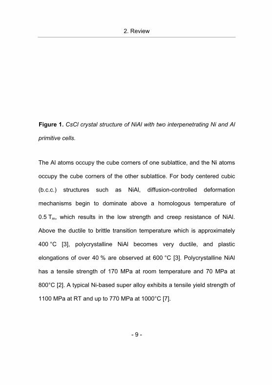
NiAl is an intermetallic compound and possesses an ordered B2
(CsCl-type) cubic crystal structure [1]. The structure consists of two
interpenetrating primitive cubic cells, as shown in figure 1.
2. Review
- 9 -
Figure 1. CsCl crystal structure of NiAl with two interpenetrating Ni and Al
primitive cells.
The Al atoms occupy the cube corners of one sublattice, and the Ni atoms
occupy the cube corners of the other sublattice. For body centered cubic
(b.c.c.) structures such as NiAl, diffusion-controlled deformation
mechanisms begin to dominate above a homologous temperature of
0.5 Tm, which results in the low strength and creep resistance of NiAl.
Above the ductile to brittle transition temperature which is approximately
400 °C [3], polycrystalline NiAl becomes very ductile, and plastic
elongations of over 40 % are observed at 600 °C [3]. Polycrystalline NiAl
has a tensile strength of 170 MPa at room temperature and 70 MPa at
800°C [2]. A typical Ni-based super alloy exhibits a tensile yield strength of
1100 MPa at RT and up to 770 MPa at 1000°C [7].
2. Review
- 10 -
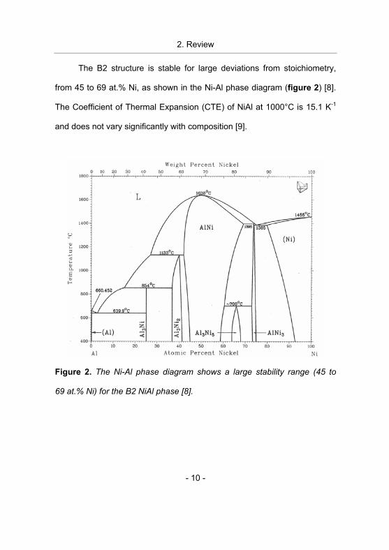
The B2 structure is stable for large deviations from stoichiometry,
from 45 to 69 at.% Ni, as shown in the Ni-Al phase diagram (figure 2) [8].
The Coefficient of Thermal Expansion (CTE) of NiAl at 1000°C is 15.1 K-1
and does not vary significantly with composition [9].
Figure 2. The Ni-Al phase diagram shows a large stability range (45 to
69 at.% Ni) for the B2 NiAl phase [8].
2. Review
- 11 -
2.1.2. IP75
NiAl with Cr and Ta alloying referred to as IP75 [10] is also
considered as matrix material in this work. The attempts to address the
challenges posed by harnessing NiAl for efficient energy conversion have
lead to the development of NiAl alloys. Zeumer and Sauthoff [11] reported
that by adding Ta to NiAl a significantly higher strength and creep
resistance can be obtained at high temperatures due to the formation of
the ternary Laves phase NiAlTa with C14 structure besides the NiAl B2
phase. However, the brittleness at room temperature and low fracture
toughness of the NiAlTa is comparable with poly crystalline NiAl. By
addition of Cr, a third Cr rich disordered phase with A2 structure is formed
and the alloy shows an improved plastic deformability and fatigue
resistance [12, 10]. It was established that the most promising composition
with respect to strength, creep resistance, brittleness, corrosion resistance,
and thermal shock resistance was 45 at.% Ni, 45 at.% Al, 7.5 at.% Cr, and
2.5 at.% Ta [10]. However, despite of improved ductility by the addition of
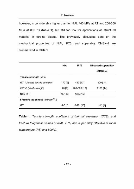
Cr the fracture toughness of IP75 at RT remains low, 6-10 MPa(m1/2) [13]
(table 1). It is comparable to that of polycrystalline NiAl, 4-6 MPa(m1/2) [2]
(table 1) and is well below the typical values for Ni based super alloys
which exceed 50 MPa(m1/2) at RT [7] (table 1). Its tensile strength at RT,
2. Review
- 12 -
however, is considerably higher than for NiAl: 440 MPa at RT and 200-300
MPa at 800 °C (table 1), but still too low for applications as structural
material in turbine blades. The previously discussed data on the
mechanical properties of NiAl, IP75, and superalloy CMSX-4 are
summarized in table 1.
NiAl IP75 Ni-based superalloy
(CMSX-4)
Tensile strength [MPa]
RT (ultimate tensile strength)
800°C (yield strength)
170 [9]
70 [9]
440 [13]
200-300 [13]
900 [14]
1100 [14]
CTE [K-1] 15.1 [9] 13.5 [15] -
Fracture toughness [MPa(m1/2)]
RT
4-6 [2]
6-10 [13]
�50 [7]
Table 1. Tensile strength, coefficient of thermal expansion (CTE), and
fracture toughness values of NiAl, IP75, and super alloy CMSX-4 at room
temperature (RT) and 800°C.
2. Review
- 13 -
2.2. Fiber reinforcement
Experimental results have consistently shown that the strength of
sapphire fibers incorporated in metallic or intermetallic matrices is reduced
during the composite fabrication process [16-22].
The main reason for this identified in the literature is a chemical
reaction between Al2O3 and matrix and/or binders and/or impurities in the
matrix material [17, 19-21]. However, thermal stresses that arise due to
CTE mismatch between fiber and matrix e.g. NiAl CTE=15.1�10-6 K-1 [9]
and �-Al2O3 fibers (c-direction) CTE=6.9�10-6 K-1 [23] (Note that these
values vary with temperature), and morphological changes of the fiber
surface due to surface diffusion of Al2O3 into matrix grain boundaries
during high temperature treatment [16-18, 20], and hot pressing induced
fiber fracture [18, 20] may also degrade the fiber strength.
2.3. Coupling concepts
Three different fiber-matrix coupling concepts are evaluated in this
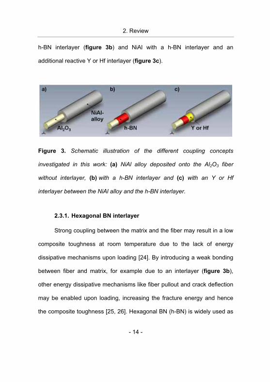
work as presented in figure 3, namely: NiAl deposited directly onto the
fiber without any interlayer (figure 3a), NiAl deposited onto the fiber with a
2. Review
- 14 -
h-BN interlayer (figure 3b) and NiAl with a h-BN interlayer and an
additional reactive Y or Hf interlayer (figure 3c).
Figure 3. Schematic illustration of the different coupling concepts
investigated in this work: (a) NiAl alloy deposited onto the Al2O3 fiber
without interlayer, (b) with a h-BN interlayer and (c) with an Y or Hf
interlayer between the NiAl alloy and the h-BN interlayer.
2.3.1. Hexagonal BN interlayer
Strong coupling between the matrix and the fiber may result in a low
composite toughness at room temperature due to the lack of energy
dissipative mechanisms upon loading [24]. By introducing a weak bonding
between fiber and matrix, for example due to an interlayer (figure 3b),
other energy dissipative mechanisms like fiber pullout and crack deflection
may be enabled upon loading, increasing the fracture energy and hence
the composite toughness [25, 26]. Hexagonal BN (h-BN) is widely used as
2. Review
- 15 -
interlayer material in brittle composites (e.g. SiC-fiber/BN/SiC-matrix
composites [27]), which due to Van der Waals bonding between the basal
planes in the hexagonal lattice [28] may deflect cracks.
Hu et al. [29] performed structural analysis of the h-BN interlayer
used here with transmission electron microscopy (TEM). It was observed
that as deposited films exhibit a turbostratic structure which transforms into
a hexagonal structure during annealing with the hexagonal basal planes
aligned along the fiber c-axis, which is beneficial for achieving low interface
shear strength due to van der Waals bonding [29]. Furthermore, it was
established that the deposited h-BN does not form reaction products with
�-Al2O3 fiber at the composite fabricating temperature which is important in
order to maintain a high fiber strength [30, 17-21]. Reichert et al. [31]
performed chemical analysis of the h-BN interlayer and established that it
contains approximately 4 at.% O and C dissolved in the h-BN.
2.3.2. Y and Hf interlayer
Reichert and co-workers proposed to introduce refractory metal
interlayers, e.g. Y or Hf, between the h-BN interlayer (figure 3c) and the
NiAl matrix to enhance the fiber matrix coupling [32]. It was envisioned that
during composite fabrication (diffusion bonding) the refractory metal reacts
2. Review
- 16 -
with the fiber improving the fiber-matrix coupling by compound formation.
The reaction path in the Al2O3/h-BN/Y system in the temperature range
1100-1300°C has been investigated earlier [32]. The effect of the presence
of the matrix material NiAl is not discussed in reference 32. Reactions
between Y and Al2O3 take place forming several different Y oxides, of
which Y3Al5O12 is the most stable one. The reaction products obtained
during annealing of the h-BN/Hf/NiAl system for 20 h at 1350 °C were
reported to be: AlN, Al2O3, HfB2 and HfN [33].
2. Review
- 17 -
List of references [1] Ductility in intermetallic compounds, A. M. Russell, Advanced
Engineering Materials 5 (2003) 629.
[2] Overview No.104 - The Physical and Mechanical Properties of
NiAl, D. B. Miracle, Acta Metallurgica Et Materialia 41 (1993) 649.
[3] Intermetallic compounds, Vol. 2, D. R. Miracle DB, (John Wiley &
Sons Ltd, 1994).
[4] The Oxidation Behavior of NiAl. 1) Phase-Transformations in
the Alumina Scale during Oxidation of NiAl and NiAl-Cr Alloys,
M. W. Brumm and H. J. Grabke, Corrosion Science 33 (1992) 1677.
[5] Effect of 0.1 at.-Percent Zirconium on the Cyclic Oxidation
Resistance of Beta-NiAl, C. A. Barrett, Oxidation of Metals 30
(1988) 361.
[6] Independent Slip Systems in Crystals, G. W. Groves and A. Kelly,
Philosophical Magazine 8 (1963) 877.
[7] Intermetallic Matrix Composites III, C. H. Ward and A. S.
Culbertson, edited by R. R. B. J.A. Graves, J.J. Lewandowski
(Materials Research Society, San Francisco, 1994), Vol. 350, p. 3.
[8] Binary alloy phase diagrams, Vol. 1, T. B. Massalski, (American
Society for Metals, , Ohio 44073, 1986).
[9] Intermetallic compounds, Vol. 2, D. B. Miracle and R. Darolia,
(John Wiley & Sons Ltd, 1994).
[10] Deformation behaviour of intermetallic NiAl-Ta alloys with
strengthening Laves phase for high-temperature applications, III) Effects of alloying with Cr, B. Zeumer and G. Sauthoff,
Intermetallics 6 (1998) 451.
2. Review
- 18 -
[11] Intermetallic NiAl-Ta alloys with strengthening Laves phase for
high temperature applications, I) Basic properties, B. Zeumer
and G. Sauthoff, Intermetallics 5 (1997) 563.
[12] Deformation behaviour of intermetallic NiAl-Ta alloys with
strengthening Laves phase for high-temperature application, 2) Effects of alloying with Nb and other elements, B. Zeumer and
G. Sauthoff, Intermetallics 5 (1997) 641.
[13] Deformation behaviour of intermetallic NiAl-Ta alloys with
strengthening Laves phase for high-temperature applications - IV. Effects of processing, B. Zeumer, W. Sanders, and
G. Sauthoff, Intermetallics 7 (1999) 889.
[14] Tensile Behavior of a New Single-Crystal Nickel-Based
Superalloy (CMSX-4) at Room and Elevated-Temperatures,
A. Sengupta, S. K. Putatunda, L. Bartosiewicz, J. Hangas,
P. J. Nailos, M. Peputapeck, and F. E. Alberts, Journal of Materials
Engineering and Performance 3 (1994) 664.
[15] Multiphase intermetallic alloys for structural applications,
G. Sauthoff, Intermetallics 8 (2000) 1101.
[16] Processing and Mechanical-Properties of Al2O3 Fiber-
Reinforced NiAl Composites, R. R. Bowman, A. K. Misra, and
S. M. Arnold, Metallurgical and Materials Transactions A-Physical
Metallurgy and Materials Science 26 (1995) 615.
[17] Effects of Composite Processing on the Strength of Sapphire
Fiber-Reinforced Composites, J. B. Davis, J. Yang, and
A. G. Evans, Acta Metallurgica Et Materialia 43 (1995) 259.
2. Review
- 19 -
[18] Effect of composite fabrication on the strength of single crystal
Al2O3 fibers in two Fe-base alloy composites, S. L. Draper and
B. J. M. Aikin, Materials Science and Engineering A-Structural
Materials Properties Microstructure and Processing 266 (1999) 18.
[19] Tensile Behavior of Al 2O3/FeAl+B and Al2O3/FeCrAlY
Composites, S. L. Draper, B. J. M. Aikin, and J. I. Eldridge,
Metallurgical and Materials Transactions a-Physical Metallurgy and
Materials Science 26 (1995) 2719.
[20] Al2O3 Fiber Strength Degradation in Metal and Intermetallic
Matrix Composites, S. L. Draper and I. E. Locci, Journal of
Materials Research 9 (1994) 1397.
[21] Influence of Interfacial Reactions on the Fiber-Matrix Interfacial
Shear-Strength in Sapphire Fiber-Reinforced NiAl(Yb) Composites, S. N. Tewari, R. Asthana, R. Tiwari, R. R. Bowman,
and J. Smith, Metallurgical and Materials Transactions A-Physical
Metallurgy and Materials Science 26 (1995) 477.
[22] Niobium Coating Effects on the Tensile-Strength of Sapphire
Fibers, E. R. Trumbauer, J. R. Hellmann, and D. A. Koss,
Composites 25 (1994) 625.
[23] Data sheet for c-axis oriented sapphire fibers, www.photran.com.
[24] Influences of Interfacial Bonding Strength and Scatter of Fiber
Strength on Tensile Behavior of Unidirectional Metal Matrix Composites, S. Ochiai and K. Osamura, Journal of Materials
Science 23 (1988) 886.
[25] Interface engineering in oxide fibre/oxide matrix composites,
K. K. Chawla, C. Coffin, and Z. R. Xu, International Materials
Reviews 45 (2000) 165.
2. Review
- 20 -
[26] Interface design for oxidation-resistant ceramic composites,
R. J. Kerans, R. S. Hay, T. A. Parthasarathy, and M. K. Cinibulk,
Journal of the American Ceramic Society 85 (2002) 2599.
[27] Effect of a boron nitride interphase that debonds between the
interphase and the matrix in SiC/SiC composites,
G. N. Morscher, H. M. Yun, J. A. DiCarlo, and L. Thomas-Ogbuji,
Journal of the American Ceramic Society 87 (2004) 104.
[28] Third-order elastic constants and pressure derivatives of the
second-order elastic constants of hexagonal boron nitride,
V. M. Mathew, C. S. Menon, and K. P. Jayachandran, Journal of
Materials Science 37 (2002) 5237.
[29] Interface structure, chemistry and properties of NiAl
composites fabricated from matrix-coated single-crystalline Al2O3 fibres (sapphire) with and without an hBN interlayer,
W. Hu, T. Weirich, B. Hallstedt, H. Chen, Y. Zhong, and G. Gottstein,
Acta Materialia 54 (2006) 2473.
[30] Strength degradation of sapphire fibers during pressure casting
of a sapphire-reinforced Ni-base superalloy, R. Asthana,
S. N. Tewari, and S. L. Draper, Metallurgical and Materials
Transactions a-Physical Metallurgy and Materials Science 29 (1998)
1527.
[31] Influence of BN fiber coatings on the interfacial structure of
sapphire fiber reinforced NiAl composites, K. Reichert, K. Wen,
R. Cremer, W. Hu, D. Neuschütz, and G. Gottstein, Applied Surface
Science 179 (2001) 150.
2. Review
- 21 -
[32] Reaction paths in the system Al2O3-hBN-Y, K. Reichert,
O. Oreshina, R. Cremer, and D. Neuschütz, Applied Surface
Science 179 (2001) 138.
[33] A new method to examine interfacial reactions of a multilayered
system NiAl-Hf-hBN on a sapphire fibre, S. Richter, S. Kyrsta,
J. M. Schneider, D. E. Hajas, and J. Mayer, Microchimica Acta 155
(2006) 257.
2. Review
- 22 -
3. Methods of research
- 23 -
3. Methods of research
In this chapter the deposition processes for interlayer and matrix
materials are described and the characterization methods used. A
description of the tensile strength measurement and the evaluation of
the measured data by statistical methods follows.
3.1. Composite fabrication
There are several methods known in the literature to incorporate
fibers into a matrix material. Examples of these are the fiber foil fiber
technique [1, 2], the powder metallurgical approach [3], and the matrix
coated fiber technique [4]. The latter was chosen in this work due to its
advantages over the other techniques, namely the homogeneous
distribution of fibers in the matrix, the precise control of fiber volume
fraction in the IMC by control of the matrix coating thickness. Most
importantly, deposition processes such as magnetron sputtering allow
the introduction of an interlayer which can be used for tailoring the fiber
matrix coupling.
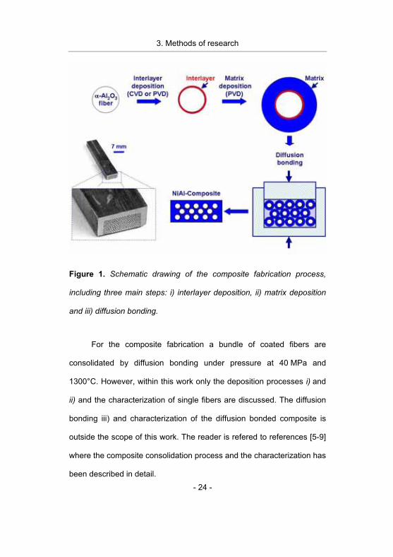
The composite fabrication process is schematically shown in
figure 1. The fabrication process includes three main steps: i) interlayer
deposition, ii) matrix deposition and iii) diffusion bonding.
3. Methods of research
- 24 -
Figure 1. Schematic drawing of the composite fabrication process,
including three main steps: i) interlayer deposition, ii) matrix deposition
and iii) diffusion bonding.
For the composite fabrication a bundle of coated fibers are
consolidated by diffusion bonding under pressure at 40 MPa and
1300°C. However, within this work only the deposition processes i) and
ii) and the characterization of single fibers are discussed. The diffusion
bonding iii) and characterization of the diffusion bonded composite is
outside the scope of this work. The reader is refered to references [5-9]
where the composite consolidation process and the characterization has
been described in detail.
3. Methods of research
- 25 -
Single crystal c-axis oriented �-Al2O3 fibers (Saphikon) with an
average diameter of approximately 130 �m were cleaned in an
ultrasonic bath, first in acetone and subsequently in methanol. Two
fiber lengths were used in this work, 75 mm and 110 mm.The interlayer
materials Y and Hf and the matrix materials IP75 and NiAl were
deposted by magnetron sputtering, whereas the h-BN interlayer was
deposited by Chemical Vapor Deposition (CVD).
3.2. Interlayer deposition
3.2.1. h-BN interlayer
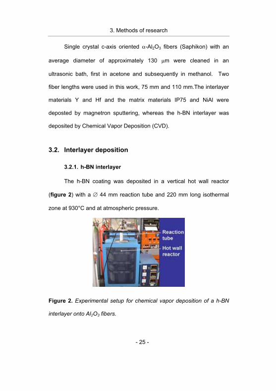
The h-BN coating was deposited in a vertical hot wall reactor
(figure 2) with a � 44 mm reaction tube and 220 mm long isothermal
zone at 930°C and at atmospheric pressure.
Figure 2. Experimental setup for chemical vapor deposition of a h-BN
interlayer onto Al2O3 fibers.
3. Methods of research
- 26 -
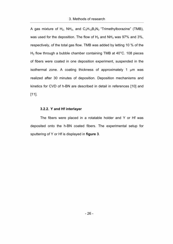
A gas mixture of H2, NH3, and C3H12B3N3 “Trimethylborazine” (TMB),
was used for the deposition. The flow of H2 and NH3 was 97% and 3%,
respectively, of the total gas flow. TMB was added by letting 10 % of the
H2 flow through a bubble chamber containing TMB at 40°C. 108 pieces
of fibers were coated in one deposition experiment, suspended in the
isothermal zone. A coating thickness of approximately 1 �m was
realized after 30 minutes of deposition. Deposition mechanisms and
kinetics for CVD of h-BN are described in detail in references [10] and
[11].
3.2.2. Y and Hf interlayer
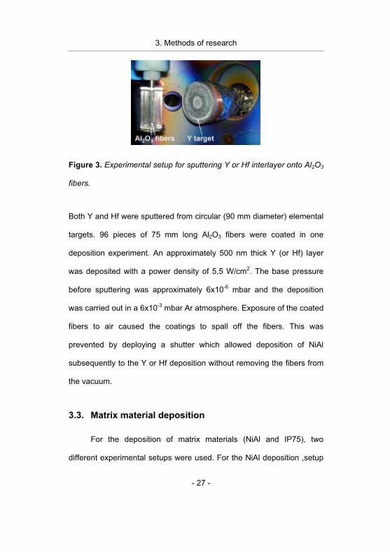
The fibers were placed in a rotatable holder and Y or Hf was
deposited onto the h-BN coated fibers. The experimental setup for
sputtering of Y or Hf is displayed in figure 3.
3. Methods of research
- 27 -
Figure 3. Experimental setup for sputtering Y or Hf interlayer onto Al2O3
fibers.
Both Y and Hf were sputtered from circular (90 mm diameter) elemental
targets. 96 pieces of 75 mm long Al2O3 fibers were coated in one
deposition experiment. An approximately 500 nm thick Y (or Hf) layer
was deposited with a power density of 5,5 W/cm2. The base pressure
before sputtering was approximately 6x10⁻⁶ mbar and the deposition
was carried out in a 6x10⁻³ mbar Ar atmosphere. Exposure of the coated
fibers to air caused the coatings to spall off the fibers. This was
prevented by deploying a shutter which allowed deposition of NiAl
subsequently to the Y or Hf deposition without removing the fibers from
the vacuum.
3.3. Matrix material deposition
For the deposition of matrix materials (NiAl and IP75), two
different experimental setups were used. For the NiAl deposition ,setup
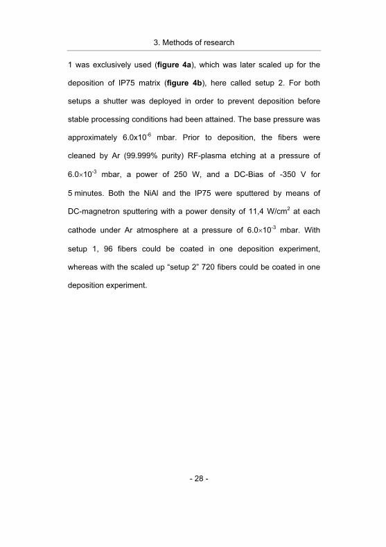
3. Methods of research
- 28 -
1 was exclusively used (figure 4a), which was later scaled up for the
deposition of IP75 matrix (figure 4b), here called setup 2. For both
setups a shutter was deployed in order to prevent deposition before
stable processing conditions had been attained. The base pressure was
approximately 6.0x10⁻⁶ mbar. Prior to deposition, the fibers were
cleaned by Ar (99.999% purity) RF-plasma etching at a pressure of
6.0�10-3 mbar, a power of 250 W, and a DC-Bias of -350 V for
5 minutes. Both the NiAl and the IP75 were sputtered by means of
DC-magnetron sputtering with a power density of 11,4 W/cm2 at each
cathode under Ar atmosphere at a pressure of 6.0�10-3 mbar. With
setup 1, 96 fibers could be coated in one deposition experiment,
whereas with the scaled up “setup 2” 720 fibers could be coated in one
deposition experiment.
3. Methods of research
- 29 -
(a) (b)
Figure 4. (a) The experimental setup for NiAl deposition (setup 1). With
this setup 96 fibers can be coated in one deposition experiment. (b) The
experimental setup for IP75 deposition (setup 2). The fiber holders
rotate according to the planetary gear principle. With this setup 720
fibers can be coated in one deposition experiment.
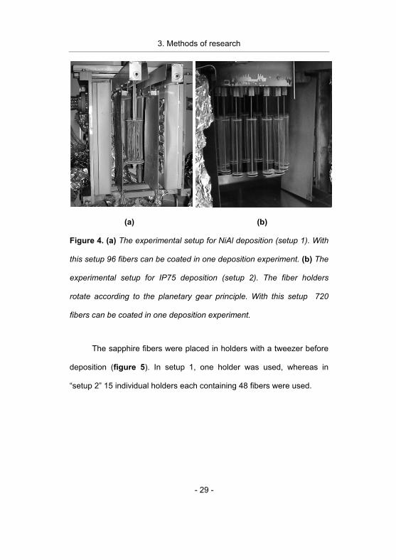
The sapphire fibers were placed in holders with a tweezer before
deposition (figure 5). In setup 1, one holder was used, whereas in
“setup 2” 15 individual holders each containing 48 fibers were used.
3. Methods of research
- 30 -
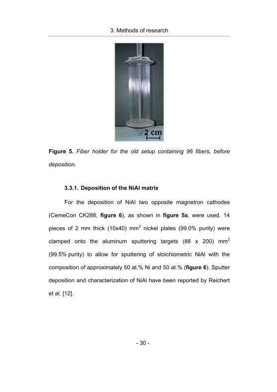
Figure 5. Fiber holder for the old setup containing 96 fibers, before
deposition.
3.3.1. Deposition of the NiAl matrix
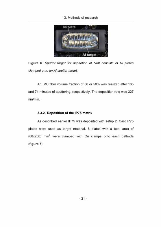
For the deposition of NiAl two opposite magnetron cathodes
(CemeCon CK288, figure 6), as shown in figure 5a, were used. 14
pieces of 2 mm thick (10x40) mm2 nickel plates (99.0% purity) were
clamped onto the aluminum sputtering targets (88 x 200) mm2
(99.5% purity) to allow for sputtering of stoichiometric NiAl with the
composition of approximately 50 at.% Ni and 50 at.% (figure 6). Sputter
deposition and characterization of NiAl have been reported by Reichert
et al. [12].
3. Methods of research
- 31 -
Figure 6. Sputter target for depsotion of NiAl consists of Ni plates
clamped onto an Al sputter target.
An IMC fiber volume fraction of 30 or 50% was realized after 165
and 74 minutes of sputtering, respectively. The deposition rate was 327
nm/min.
3.3.2. Deposition of the IP75 matrix
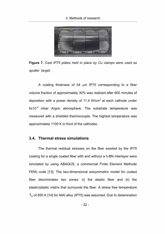
As described earlier IP75 was deposited with setup 2. Cast IP75
plates were used as target material. 8 plates with a total area of
(88x200) mm2 were clamped with Cu clamps onto each cathode
(figure 7).
3. Methods of research
- 32 -
Figure 7. Cast IP75 plates held in place by Cu clamps were used as
sputter target.
A coating thickness of 54 �m IP75 corresponding to a fiber
volume fraction of approximately 30% was realized after 600 minutes of
deposition with a power density of 11.4 W/cm2 at each cathode under
6x10⁻³ mbar Argon atmosphere. The substrate temperature was
measured with a shielded thermocouple. The highest temperature was
approximately 1100 K in front of the cathodes.
3.4. Thermal stress simulations
The thermal residual stresses on the fiber exerted by the IP75
coating for a single coated fiber with and without a h-BN interlayer were
simulated by using ABAQUS, a commercial Finite Element Methode
FEM) code [13]. The two-dimensional axisymmetric model for coated
fiber discriminates two zones: (i) the elastic fiber and (ii) the
elastic/plastic matrix that surrounds the fiber. A stress free temperature
Tsf of 850 K [14] for NiAl alloy (IP75) was assumed. Due to delamination
3. Methods of research
- 33 -
of the h-BN basal planes [7], the interface in the NiAl composite with h-
BN interlayer was considered to be a purely frictional interface with a
friction coefficient of �f = 0.21. Details on the model description can be
found in reference [15].
3.5. Tensile testing
The fiber tensile strength at room temperature and ambient
humidity was measured by using an in-house built pull test machine
(figure 8a). The two ends of the fibers were glued to metal plates
containing grooves which were attached to a holder (figure 8b). This
assures that the fibers are pulled perpendicular to the fiber axis and
provide an easy way to insert and attach the fiber ends to the
crossheads of the pull test machine (figure 8a).
3. Methods of research
- 34 -
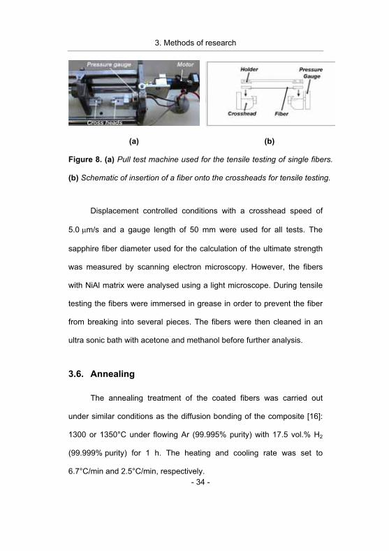
(a) (b)
Figure 8. (a) Pull test machine used for the tensile testing of single fibers.
(b) Schematic of insertion of a fiber onto the crossheads for tensile testing.
Displacement controlled conditions with a crosshead speed of
5.0 �m/s and a gauge length of 50 mm were used for all tests. The
sapphire fiber diameter used for the calculation of the ultimate strength
was measured by scanning electron microscopy. However, the fibers
with NiAl matrix were analysed using a light microscope. During tensile
testing the fibers were immersed in grease in order to prevent the fiber
from breaking into several pieces. The fibers were then cleaned in an
ultra sonic bath with acetone and methanol before further analysis.
3.6. Annealing
The annealing treatment of the coated fibers was carried out
under similar conditions as the diffusion bonding of the composite [16]:
1300 or 1350°C under flowing Ar (99.995% purity) with 17.5 vol.% H2
(99.999% purity) for 1 h. The heating and cooling rate was set to
6.7°C/min and 2.5°C/min, respectively.
3. Methods of research
- 35 -
3.7. Etching
Two different solutions were used to remove the coating from the
fibers: 1) 33 vol.% nitric acid (HNO3), 17 vol.% hydrochloric acid (HCl)
and 50 vol.% deionized water or 2) 23 vol.% nitric acid (HNO3), 54 vol.%
hydrochloric acid (HCl) and 23 vol.% deionized water. The coatings
were removed more efficiently in the latter solution. Tensile strengths of
as received and etched fibers were compared, and no difference in
strength was established. Hence the etching solutions do not affect the
tensile stenght of the fibers.
3.8. Characterization
3.8.1. Morphology and fracture surface analysis
Fracture surface morphologies were evaluated and fracture
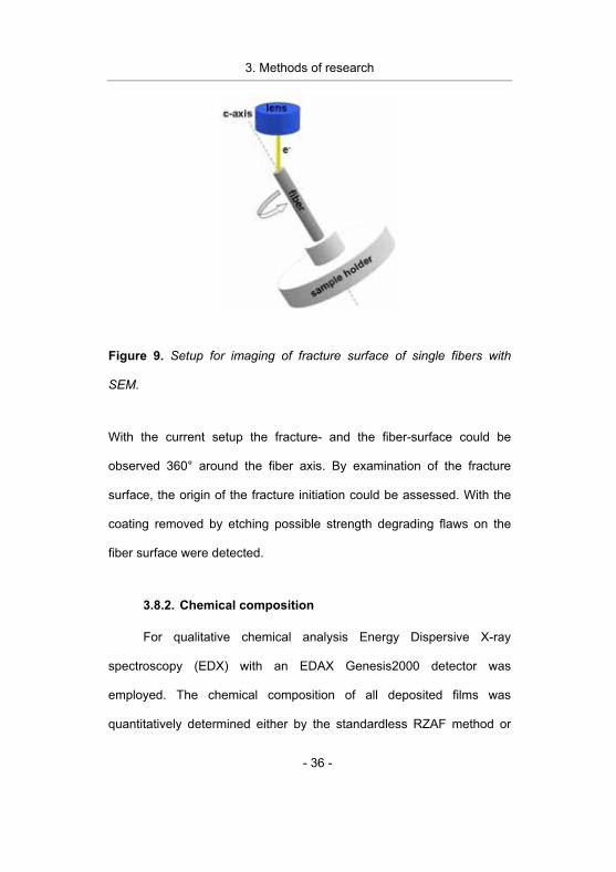
initiation sites were identified by imaging fracture and fiber surfaces
with a JEOL JSM-6480 Scanning Electron Microscope (SEM). The
fractured fibers were placed in a sample holder in the microscope
according to the schematic drawing (figure 9).
3. Methods of research
- 36 -
Figure 9. Setup for imaging of fracture surface of single fibers with
SEM.
With the current setup the fracture- and the fiber-surface could be
observed 360° around the fiber axis. By examination of the fracture
surface, the origin of the fracture initiation could be assessed. With the
coating removed by etching possible strength degrading flaws on the
fiber surface were detected.
3.8.2. Chemical composition
For qualitative chemical analysis Energy Dispersive X-ray
spectroscopy (EDX) with an EDAX Genesis2000 detector was
employed. The chemical composition of all deposited films was
quantitatively determined either by the standardless RZAF method or
3. Methods of research
- 37 -
using a compound standard, where the composition of the standard was
determined by Wavelength Dispersive X-ray spectroscopy (WDX). The
constituents of reaction products, percipitates etc. detected on fiber
surfaces were only qualitatively determined. The reason for this is the
limitation of EDX analysis method to quantitatively determine the
composition of a material that is not homogeneous and microscopically
smooth.
Focused Ion Beam (FIB) was used to expose the reaction zone in
the h-BN/Y/NiAl and h-BN/Hf/NiAl specimens by milling a bevel in the
matrix and interlayers with a Ga+ ion beam according to the principle
demonstrated in figure 10.
3. Methods of research
- 38 -
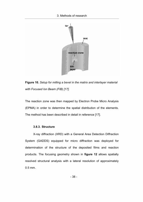
Figure 10. Setup for milling a bevel in the matrix and interlayer material
with Focused Ion Beam (FIB) [17].
The reaction zone was then mapped by Electron Probe Micro Analysis
(EPMA) in order to determine the spatial distribution of the elements.
The method has been described in detail in reference [17].
3.8.3. Structure
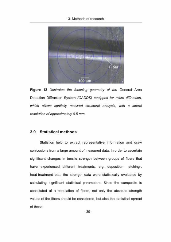
X-ray diffraction (XRD) with a General Area Detection Diffraction
System (GADDS) equipped for micro diffraction was deployed for
determination of the structure of the deposited films and reaction
products. The focusing geometry shown in figure 12 allows spatially
resolved structural analysis with a lateral resolution of approximately
0.5 mm.
3. Methods of research
- 39 -
Figure 12 illustrates the focusing geometry of the General Area
Detection Diffraction System (GADDS) equipped for micro diffraction,
which allows spatially resolved structural analysis, with a lateral
resolution of approximately 0.5 mm.
3.9. Statistical methods
Statistics help to extract representative information and draw
conlcusions from a large amount of measured data. In order to ascertain
significant changes in tensile strength between groups of fibers that
have experienced different treatments, e.g. deposition-, etching-,
heat-treatment etc., the strength data were statistically evaluated by
calculating significant statistical parameters. Since the composite is
constituted of a population of fibers, not only the absolute strength
values of the fibers should be considered, but also the statistical spread
of these.
3. Methods of research
- 40 -
3.9.1. Weibull Modulus
Ceramic fibers are brittle and a fracture is initiated at the surface
flaw that generates the largest stress intensity according to the Griffith
theory [18]. These strength limiting flaws can be morphologic or internal
inhomogeneities like chemical reaction sites or pores. The flaws are a
member of some determinable distribution [18]. It has been proven that
the Weibull distribution [19] is usedfull for describing the ultimate
strength of ceramic fibers. In its simplest form it can be described by the
two parameter relation:
���
�
� �
����
����
mc
cP0
exp1)(��
� ,
were P is the probability of failure, m is the Weibull modulus, �c is the
uniaxial tensile stress to rupture, and �0 is a scale parameter with the
same dimension as �c. From the equation above a linear relation exists,
when ln(ln(1/1-P)) is plotted against ln (�C):
� � � �0lnln)(1
1lnln ���
mmP c
c
�����
�
� �
����
��
.
From this equation it can be seen that m is the slope of a straigh line
and m�ln(�0) is the y intercept. P(�c) is a cumulative probability function,
3. Methods of research
- 41 -
also called estimator and has a value between zero and one. Several
forms of estimators exist, but for small sample sizes the estimator has
proved to have its most appropriate form:
� �N
Pi5,0i �
� ,
where i is the ith result of the ranked critical fracture stresses (�c,,i) [20,
21]. Based on these equations and the strength data, a Weibull diagram
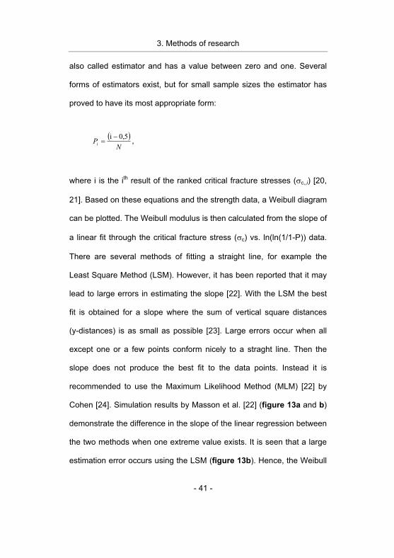
can be plotted. The Weibull modulus is then calculated from the slope of
a linear fit through the critical fracture stress (�c) vs. ln(ln(1/1-P)) data.
There are several methods of fitting a straight line, for example the
Least Square Method (LSM). However, it has been reported that it may
lead to large errors in estimating the slope [22]. With the LSM the best
fit is obtained for a slope where the sum of vertical square distances
(y-distances) is as small as possible [23]. Large errors occur when all
except one or a few points conform nicely to a straght line. Then the
slope does not produce the best fit to the data points. Instead it is
recommended to use the Maximum Likelihood Method (MLM) [22] by
Cohen [24]. Simulation results by Masson et al. [22] (figure 13a and b)
demonstrate the difference in the slope of the linear regression between
the two methods when one extreme value exists. It is seen that a large
estimation error occurs using the LSM (figure 13b). Hence, the Weibull
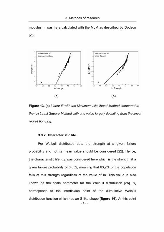
3. Methods of research
- 42 -
modulus m was here calculated with the MLM as described by Dodson
[25].
(a) (b)
Figure 13. (a) Linear fit with the Maximum Likelihood Method compared to
the (b) Least Square Method with one value largely deviating from the linear
regression [22].
3.9.2. Characteristic life
For Weibull distributed data the strength at a given failure
probability and not its mean value should be considered [22]. Hence,
the characteristic life, �0, was considered here which is the strength at a
given failure probability of 0,632, meaning that 63,2% of the population
fails at this strength regardless of the value of m. This value is also
known as the scale parameter for the Weibull distribution [25]. �0
corresponds to the interflexion point of the cumulative Weibull
distribution function which has an S like shape (figure 14). At this point
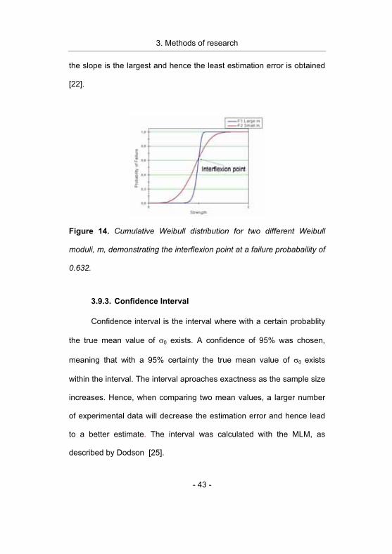
3. Methods of research
- 43 -
the slope is the largest and hence the least estimation error is obtained
[22].
Figure 14. Cumulative Weibull distribution for two different Weibull
moduli, m, demonstrating the interflexion point at a failure probabaility of
0.632.
3.9.3. Confidence Interval
Confidence interval is the interval where with a certain probablity
the true mean value of �0 exists. A confidence of 95% was chosen,
meaning that with a 95% certainty the true mean value of �0 exists
within the interval. The interval aproaches exactness as the sample size
increases. Hence, when comparing two mean values, a larger number
of experimental data will decrease the estimation error and hence lead
to a better estimate. The interval was calculated with the MLM, as
described by Dodson [25].
3. Methods of research
- 44 -
List of references [1] Fabrication of metal-matrix composites by hot-triaxial-
compaction of foil/fiber/foil lay-ups, P. D. Nicolaou and
H. R. Piehler, Scripta Materialia 39 (1998) 1077.
[2] Influence of BN fiber coatings on the interfacial structure of sapphire fiber reinforced NiAl composites, K. Reichert,
K. Wen, R. Cremer, W. Hu, D. Neuschütz, and G. Gottstein,
Applied Surface Science 179 (2001) 150.
[3] Intermetallic Fe-Al layers obtained by the powder cloth
method, F. Binczyk, S. T. Skrzypek, and A. Gierek, Powder
Technology 94 (1997) 259.
[4] Fiber Coating Concepts for Brittle-Matrix Composites,
J. B. Davis, J. P. A. Lofvander, A. G. Evans, E. Bischoff, and
M. L. Emiliani, Journal of the American Ceramic Society 76
(1993) 1249.
[5] Thermal residual stress (TRS) analysis in continuous Al2O3
fiber reinforced NiAl composite, H. Chen, W. Hu, A. Atiser, Y.
Zhong, and G. Gottstein, International journal of materials
research 97 (2006) 10.
[6] High-temperature creep behavior and hotpressing
consolidation of NiAl, H. Chen, W. P. Hu, Y. L. Zhong, and
G. Gottstein, Zeitschrift Fur Metallkunde 95 (2004) 1074.
[7] Interface structure, chemistry and properties of NiAl
composites fabricated from matrix-coated single-crystalline Al2O3 fibres (sapphire) with and without an hBN interlayer,
W. Hu, T. Weirich, B. Hallstedt, H. Chen, Y. Zhong, and G.
Gottstein, Acta Materialia 54 (2006) 2473.
3. Methods of research
- 45 -
[8] Long fibre reinforced NiAl: High temperature material for
turbine blades, M. Rosefort, C. Dahmen, A. Buhrig-Polaczek,
W. P. Hu, H. Chen, Y. L. Zhong, G. Gottstein, D. E. Hajas, and J.
M. Schneider, Advanced Engineering Materials 8 (2006) 730.
[9] Microstructure and mechanical properties of continuous
Al2O3 fibre reinforced Ni45Al45Cr7.5Ta2.5 alloy (IP75) matrix composites, Y. Zhong, D. E. Hajas, W. Hu, H. Chen, and G.
Gottstein, Philosophical Magazine A 87 (2007) 1019
[10] Constitution and deposition mechanisms of hexagonal boron nitride formed by CVD from trimethylborazine
A. Jörg, E. Zimmermann, M. Schierling, R. Cremer, and
D. Neuschütz, in CVD XIV and Euro CVD-11, The
Electrochemical Society (Pennington, USA, 1997).
[11] Kinetics of Chemical-Vapor-Deposition of Boron-Nitride from
a Gas-Mixture of Trimethylborazine, Ammonia, and Hydrogen at 900 to 1050-Degrees-C and 1 Bar Total Pressure, A. Jörg,
D. Neuschutz, and E. Zimmermann, Journal De Physique Iv 5
(1995) 167.
[12] Sputter deposition and film characterization of NiAl on
sapphire fibres, K. Reichert, C. Martinez, S. Kyrsta, R. Cremer,
and D. Neuschütz, Vacuum 71 (2003) 241.
[13] ABAQUS User’s Manual, Version 6.3, Vol. K. Hibbit, Sorensen.,
(Providence, 2002).
[14] Processing and Mechanical-Properties of Al2O3 Fiber-Reinforced NiAl Composites, R. R. Bowman, A. K. Misra, and
S. M. Arnold, Metallurgical and Materials Transactions A-Physical
Metallurgy and Materials Science 26 (1995) 615.
3. Methods of research
- 46 -
[15] Finite-element analysis of the hot-pressing consolidation of
continuous Al2O3 ribers-reinforced NiAl composites, H. Chen,
W. Hu, and G. Gottstein, Zeitschrift Fur Metallkunde 96 (2005)
710.
[16] Untersuchungen zu chemischer Stabilität,
Grenzflächenstruktur und Debonding-Verhalten der von kontinuierlichen Al2O3-Fasern verstärkten NiAl-
Verbundwerkstoffe W. Hu, K. Wen, H. Chen, S. Kyrsta, and G. Gottstein,
Verbundwerkstoffe und Werkstoffverbunde, (Wien, 2003), 153.
[17] A new method to examine interfacial reactions of a
multilayered system NiAl-Hf-hBN on a sapphire fibre,
S. Richter, S. Kyrsta, J. M. Schneider, D. E. Hajas, and J. Mayer,
Microchimica Acta 155 (2006) 257.
[18] Fracture of Brittle Solids-Second Edition, B. Lawn,
(Cambridge University Press, 1975).
[19] A Statistical Distribution Function of Wide Applicability,
W. Weibull, Journal of Applied Mechanics-Transactions of the
Asme 18 (1951) 293.
[20] On the Estimation of the Weibull Modulus, B. Bergman,
Journal of Materials Science Letters 3 (1984) 689.
[21] Experimental Probability Estimators for Weibull Plots,
J. D. Sullivan and P. H. Lauzon, Journal of Materials Science
Letters 5 (1986) 1245.
[22] Some Guidelines for a Consistent Use of the Weibull
Statistics with Ceramic Fibers, J. J. Masson and E. Bourgain,
International Journal of Fracture 55 (1992) 303.
[23] Statistical Techniques in Business & Economics, J. N. Brown,
Journal of the American Statistical Association 74 (1979) 728
3. Methods of research
- 47 -
[24] Multi-Censored Sampling in 3 Parameter Weibull
Distribution, A. C. Cohen, Technometrics 17 (1975) 347.
[25] Weibull Analysis, B. Dodson, (ASQ Quality Press, Wisconsin,
1994).
3. Methods of research
- 48 -
4. Results and discussion
- 49 -
4. Results and discussion
The goal of this work is to identify strength degradation relevant
mechanisms active during composite fabrication in sapphire fiber
reinforced NiAl or IP75 with or without a h-BN or Y (or Hf) + h-BN
interlayer. Chemical composition, structure, and morphology of the
deposited matrix- and interlayer-materials before and after annealing as
well as results from the tensile testing and the subsequent characterization
are presented in section 4.1 and 4.2. The effect of different interlayers and
matrix materials as well as processing conditions and heat treatment on
the fiber strength is discussed and strength degradation mechanisms are
identified.
4.1. Characterization of the matrix- and interlayer
materials
In the following section, the chemical composition, the structure, and
the morphology of the deposited matrix and interlayer materials before and
after annealing are presented. These data are important for process
development and for determining the effect of heat treatment on the
structure and chemistry of the interlayer and matrix materials.
4. Results and discussion
- 50 -
4.1.1. NiAl matrix
The composition of the as deposited NiAl was approximately Ni0.55Al0.45
and hence within the stability range of the B2 NiAl phase between 45 to 69
at.% Ni [1]. The X-ray diffractogram of the sputtered NiAl indicates phase
pure NiAl (diffractogram i in figure 1). After annealing in Ar + H2
atmosphere, traces of �-Al2O3 were detected (diffractogram ii in figure 1).
All sputtered films contained 4-5 at.% oxygen which may be incorporated
in the NiAl during the sputtering process. �-Al2O3 has been observed in the
NiAl by transmission electron microscope (TEM), which may have been
formed due to a reaction between Al and the O incorporated in the NiAl
matrix during deposition [2].
4. Results and discussion
- 51 -
Figure 1. i) X-ray diffraction data indicate the presence of pure NiAl before
annealing. ii) After annealing the formation of �-Al2O3 was detected.
Sputtered NiAl is growing with a columnar structure (figure 2a)
which transforms into dense NiAl after annealing (figure 2b). A thin Al2O3
scale is formed on the surface of the NiAl during annealing (figure 2b).
This observation indicates that the �-Al2O3 observed by XRD
(diffractogram ii in figure 1) may also be formed during the annealing
treatment due to reaction between Al and residual oxygen in the annealing
atmosphere.
4. Results and discussion
- 52 -
(a) (b)
Figure 2. Cross sectional scanning electron microscope images of NiAl on
�-Al2O3 fibers: (a) Columnar growth morphology of as deposited NiAl. (b)
After annealing a thin Al2O3 scale is formed on the NiAl surface.
4.1.2. IP75 Matrix
The chemical composition of the cast IP75 target was: Ni: 45.2 at.%,
Al: 45.5 at.%, Cr: 6.6 at.% and Ta: 2.7 at.% (figure 3a), which is close to
the composition of IP75 defined by Sauthoff et. al. [3], namely: Ni:
45.0 at.%, Al: 45.0 at.%, Cr: 7.5 at.% and Ta: 2.5 at.%. The deposited films
were Ni depleted (Ni: 38.9 at.%) (figure 3a coating (a)), and hence
according to the Ni-Al phase diagram, Al3Ni2 and NiAl phases may be
present (figure 3b, coating (a)). The Ni content was increased to 43.8 at.%
(figure 3a and b, coating (b)) by sputtering additional Ni by attaching a Ni
plate on the sputtering target.
4. Results and discussion
- 53 -
(a) (b)
Figure 3. (a) Chemical composition of the IP75 target and the sputtered
IP75 films. (b) Ni-Al phase diagram [1].
The resulting films consisted of phase pure NiAl as shown in the X-ray
diffractogram (figure 4). However, during annealing hexagonal- and cubic-
Cr2Ta laves phases are formed. These results indicate that Cr and Ta are
dissolved in NiAl after deposition. �-Al2O3 was also detected after
annealing and may be formed by reaction between Al and the dissolved
oxygen and/or oxygen from the annealing atmosphere as discussed
earlier.
4. Results and discussion
- 54 -
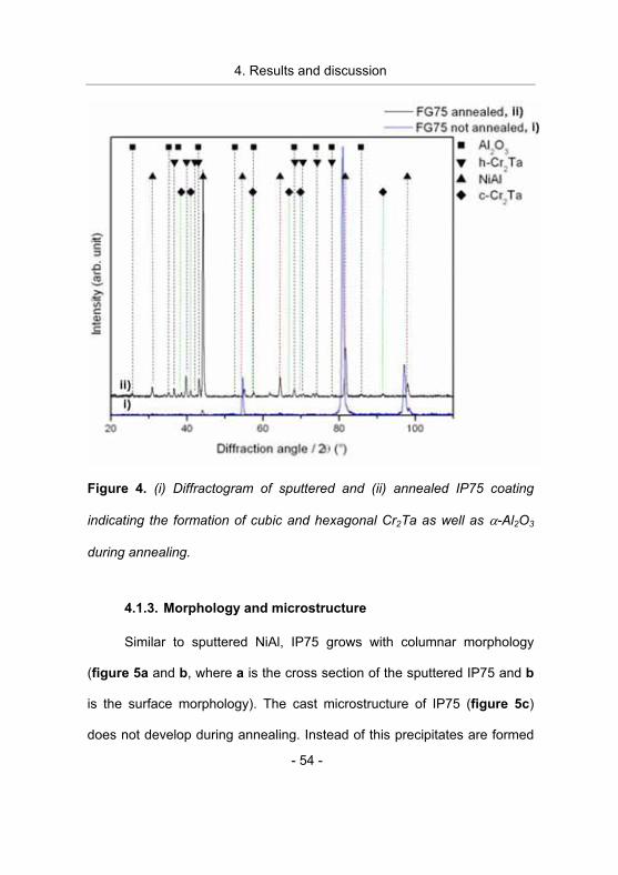
Figure 4. (i) Diffractogram of sputtered and (ii) annealed IP75 coating
indicating the formation of cubic and hexagonal Cr2Ta as well as �-Al2O3
during annealing.
4.1.3. Morphology and microstructure
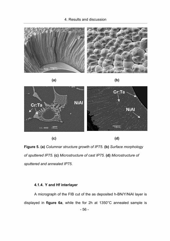
Similar to sputtered NiAl, IP75 grows with columnar morphology
(figure 5a and b, where a is the cross section of the sputtered IP75 and b
is the surface morphology). The cast microstructure of IP75 (figure 5c)
does not develop during annealing. Instead of this precipitates are formed
4. Results and discussion
- 55 -
along the columnar grain boundaries (figure 5d) which are developed
during deposition. The chemical composition data suggest that the
precipitates contain Cr and Ta. It is reasonable to assume that the
precipitates constitute the Cr2Ta Laves phase detected with XRD after
annealing.
4. Results and discussion
- 56 -
(a) (b)
(c) (d)
Figure 5. (a) Columnar structure growth of IP75. (b) Surface morphology
of sputtered IP75. (c) Microstructure of cast IP75. (d) Microstructure of
sputtered and annealed IP75.
4.1.4. Y and Hf interlayer
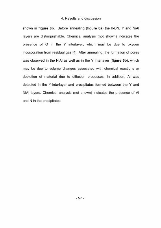
A micrograph of the FIB cut of the as deposited h-BN/Y/NiAl layer is
displayed in figure 6a, while the for 2h at 1350°C annealed sample is
4. Results and discussion
- 57 -
shown in figure 6b. Before annealing (figure 6a) the h-BN, Y and NiAl
layers are distinguishable. Chemical analysis (not shown) indicates the
presence of O in the Y interlayer, which may be due to oxygen
incorporation from residual gas [4]. After annealing, the formation of pores
was observed in the NiAl as well as in the Y interlayer (figure 6b), which
may be due to volume changes associated with chemical reactions or
depletion of material due to diffusion processes. In addition, Al was
detected in the Y-interlayer and precipitates formed between the Y and
NiAl layers. Chemical analysis (not shown) indicates the presence of Al
and N in the precipitates.
4. Results and discussion
- 58 -
(a) (b)
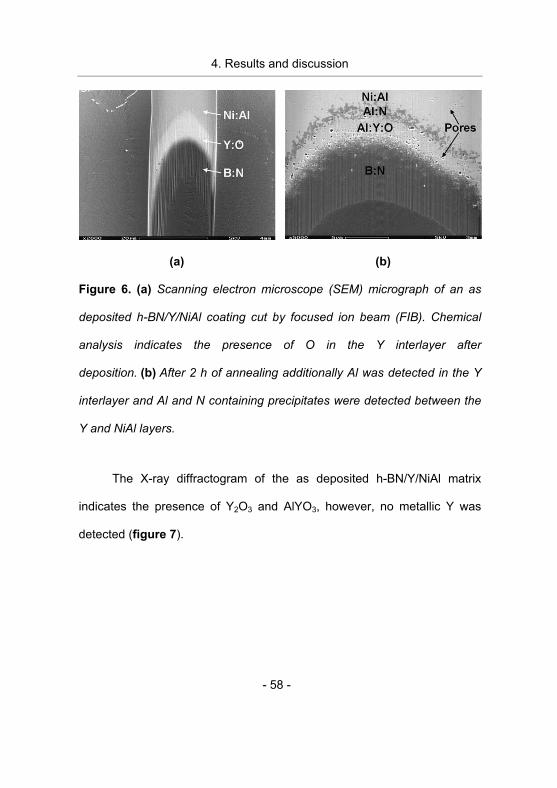
Figure 6. (a) Scanning electron microscope (SEM) micrograph of an as
deposited h-BN/Y/NiAl coating cut by focused ion beam (FIB). Chemical
analysis indicates the presence of O in the Y interlayer after
deposition. (b) After 2 h of annealing additionally Al was detected in the Y
interlayer and Al and N containing precipitates were detected between the
Y and NiAl layers.
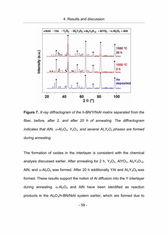
The X-ray diffractogram of the as deposited h-BN/Y/NiAl matrix
indicates the presence of Y2O3 and AlYO3, however, no metallic Y was
detected (figure 7).
4. Results and discussion
- 59 -
Figure 7. X-ray diffractogram of the h-BN/Y/NiAl matrix separated from the
fiber, before, after 2, and after 20 h of annealing. The diffractogram
indicates that AlN, �-Al2O3, Y2O3, and several AlxYyOz phases are formed
during annealing.
The formation of oxides in the interlayer is consistent with the chemical
analysis discussed earlier. After annealing for 2 h, Y2O3, AlYO3, Al3Y5O12,
AlN, and �-Al2O3 was formed. After 20 h additionally YAl and Al2Y4O9 was
formed. These results support the notion of Al diffusion into the Y interlayer
during annealing. �-Al2O3 and AlN have been identified as reaction
products in the Al2O3/h-BN/NiAl system earlier, which are formed due to
4. Results and discussion
- 60 -
reaction between Al and O incorporated in the NiAl matrix, and between h-
BN and NiAl, respectively [2].
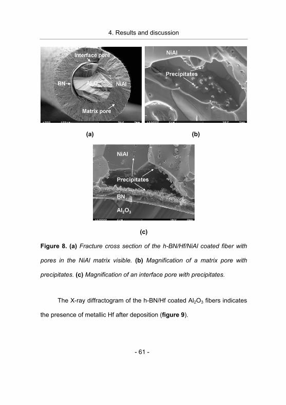
SEM investigation of cross sections of annealed sapphire fibers with
a h-BN/Hf/NiAl coating showed extensive pore formation in the NiAl matrix
along the columnar grain growth boundaries (figure 8a and b) as well as
on the h-BN/Hf, Hf/NiAl interface (figure 8c). After 20 h of annealing time
the fraction of pores in the matrix and on the interface increased. Within
the pore walls and along the NiAl grain boundaries precipitates were
detected (figure 8b and c) which may be formed by diffusion processes
and/or chemical reactions.
4. Results and discussion
- 61 -
(a) (b)
(c)
Figure 8. (a) Fracture cross section of the h-BN/Hf/NiAl coated fiber with
pores in the NiAl matrix visible. (b) Magnification of a matrix pore with
precipitates. (c) Magnification of an interface pore with precipitates.
The X-ray diffractogram of the h-BN/Hf coated Al2O3 fibers indicates
the presence of metallic Hf after deposition (figure 9).
4. Results and discussion
- 62 -
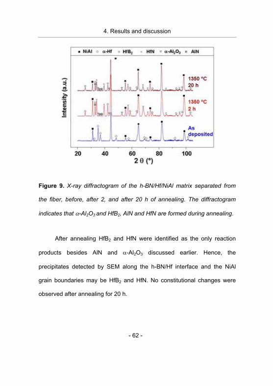
Figure 9. X-ray diffractogram of the h-BN/Hf/NiAl matrix separated from
the fiber, before, after 2, and after 20 h of annealing. The diffractogram
indicates that �-Al2O3 and HfB2, AlN and HfN are formed during annealing.
After annealing HfB2 and HfN were identified as the only reaction
products besides AlN and �-Al2O3 discussed earlier. Hence, the
precipitates detected by SEM along the h-BN/Hf interface and the NiAl
grain boundaries may be HfB2 and HfN. No constitutional changes were
observed after annealing for 20 h.
4. Results and discussion
- 63 -
4.2. Fiber strength
In the following section the effect of different interlayers and matrix
materials as well as processing conditions and heat treatment on the fiber
strength is discussed in order to identify the strength degradation relevant
mechanisms active in the composites.
4.2.1. Tensile strength of NiAl coated sapphire fibers with and
without a h-BN interlayer
The characteristic strength values measured for as-received �-Al2O3
fibers as well as NiAl coated fibers with and without a h-BN interlayer
before and after heat treatment are displayed in figure 10.
4. Results and discussion
- 64 -
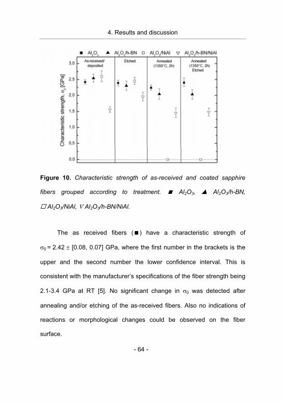
Figure 10. Characteristic strength of as-received and coated sapphire
fibers grouped according to treatment. � Al2O3, � Al2O3/h-BN,
� Al2O3/NiAl, � Al2O3/h-BN/NiAl.
The as received fibers (�) have a characteristic strength of
�0 = 2.42 � [0.08, 0.07] GPa, where the first number in the brackets is the
upper and the second number the lower confidence interval. This is
consistent with the manufacturer’s specifications of the fiber strength being
2.1-3.4 GPa at RT [5]. No significant change in �0 was detected after
annealing and/or etching of the as-received fibers. Also no indications of
reactions or morphological changes could be observed on the fiber
surface.
4. Results and discussion
- 65 -
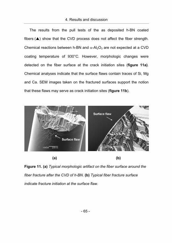
The results from the pull tests of the as deposited h-BN coated
fibers (�) show that the CVD process does not affect the fiber strength.
Chemical reactions between h-BN and �-Al2O3 are not expected at a CVD
coating temperature of 930°C. However, morphologic changes were
detected on the fiber surface at the crack initiation sites (figure 11a).
Chemical analyses indicate that the surface flaws contain traces of Si, Mg
and Ca. SEM images taken on the fractured surfaces support the notion
that these flaws may serve as crack initiation sites (figure 11b).
(a) (b)
Figure 11. (a) Typical morphologic artifact on the fiber surface around the
fiber fracture after the CVD of h-BN. (b) Typical fiber fracture surface
indicate fracture initiation at the surface flaw.
4. Results and discussion
- 66 -
Results from the chemical analysis and the SEM investigation
indicate that chemical reactions between the contaminants and the fiber
give rise to morphologic changes. Possible sources of the contamination
include the CVD reactor tube, the precursor gases and the cleaning
agents.
Similar morphologic changes in the vicinity of the crack initiation
sites, with the same contaminants, were observed on h-BN coated fibers
which were subsequently coated with NiAl (�). However, with the NiAl
coating on top of the h-BN interlayer the fiber strength decreased
significantly to �0 = 1.56 � [0.09, 0.10] GPa which corresponds to
approximately 64% of the initial sapphire fiber strength. The decrease in
fiber strength may be due to thermal stress that arises upon cooling after
the NiAl coating process. The altered morphology may act as stress
concentration site. The compressive stress may induce micro cracks
around the surface flaws thus decreasing the strength of the fiber. When
the NiAl was removed by subsequent etching, the strength of the fibers
increased to �0 = 1.96 � [0.13, 0.14] GPa which indicate that thermal
stresses are released, but the fibers do not retain their initial strength which
is consistent with the notion discussed above.
After annealing of the h-BN coated fibers 84 % of their initial strength
was retained, �0 = 2.04 � [0.18, 0.16], whereas the strength of h-BN/NiAl
4. Results and discussion
- 67 -
coated fibers decreased to 1.45 � [0.16, 0.14] GPa, which corresponds to
approximately 60 % of the initial strength. On the h-BN/NiAl coated fibers
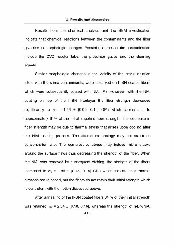
after annealing additionally ridges were observed on the fiber surface
meandering along the fiber surface (figure 12).
Figure 12. Ridge formation on the fiber surface of a BN/NiAl coated fiber
after annealing.
No evidence for contamination was detected on the ridges. Different
thermal expansion coefficients of �-Al2O3, BN, and NiAl may cause the BN
interlayer to crack during the annealing process. The ridges can then be
formed due to surface diffusion of Al2O3 into the cracks in the BN. SEM
analysis of the fractured surface indicate that the fracture initiates at the
ridges and at sites where chemical reactions have taken place. Thermal
4. Results and discussion
- 68 -
stresses from the NiAl in combination with the altered surface morphology
may be responsible for the decrease in fiber strength observed here.
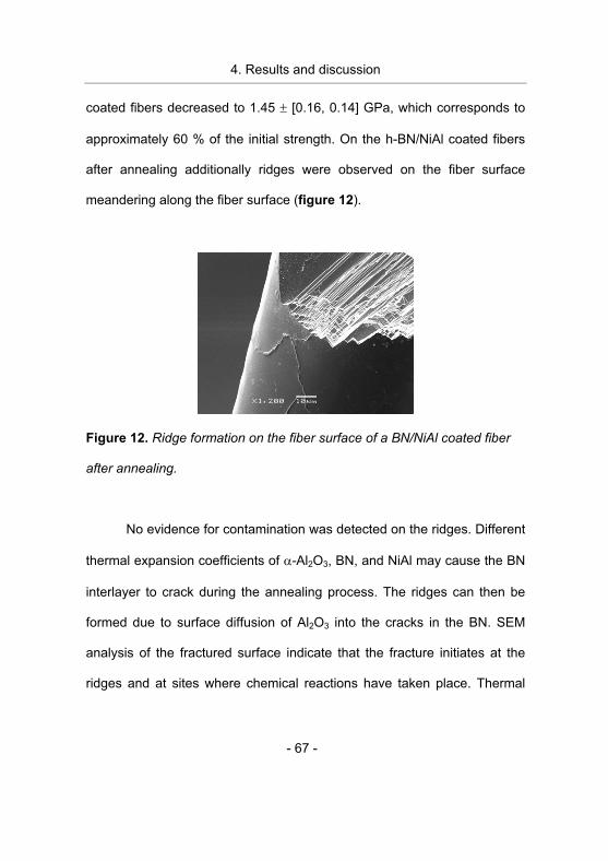
Fibers coated with NiAl (�) did not exhibit any significant change in
critical strength neither with coating nor with the coating etched away. No
morphological changes or chemical reactions could be identified. However,
during the annealing process all the coated fibers broke into pieces.
Fractured fibers large enough for pull testing cracked upon handling with
tweezers. Hence, the strength was assumed to be zero, �0 = 0. Fiber
pieces examined by optical microscopy after etching showed severe
cracking of the fiber (figure 13a). Surface cracks could be identified by
SEM, which also revealed grain boundary like imprints on the fiber surface
(figure 13b).
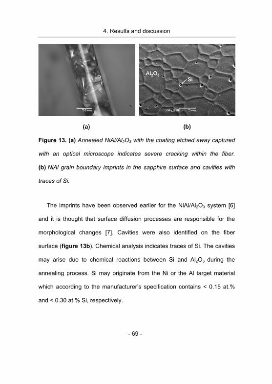
4. Results and discussion
- 69 -
(a) (b)
Figure 13. (a) Annealed NiAl/Al2O3 with the coating etched away captured
with an optical microscope indicates severe cracking within the fiber.
(b) NiAl grain boundary imprints in the sapphire surface and cavities with
traces of Si.
The imprints have been observed earlier for the NiAl/Al2O3 system [6]
and it is thought that surface diffusion processes are responsible for the
morphological changes [7]. Cavities were also identified on the fiber
surface (figure 13b). Chemical analysis indicates traces of Si. The cavities
may arise due to chemical reactions between Si and Al2O3 during the
annealing process. Si may originate from the Ni or the Al target material
which according to the manufacturer’s specification contains < 0.15 at.%
and < 0.30 at.% Si, respectively.
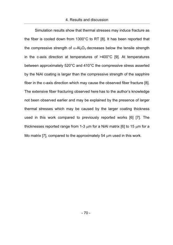
4. Results and discussion
- 70 -
Simulation results show that thermal stresses may induce fracture as
the fiber is cooled down from 1300°C to RT [8]. It has been reported that
the compressive strength of �-Al2O3 decreases below the tensile strength
in the c-axis direction at temperatures of >400°C [9]. At temperatures
between approximately 520°C and 410°C the compressive stress asserted
by the NiAl coating is larger than the compressive strength of the sapphire
fiber in the c-axis direction which may cause the observed fiber fracture [8].
The extensive fiber fracturing observed here has to the author’s knowledge
not been observed earlier and may be explained by the presence of larger
thermal stresses which may be caused by the larger coating thickness
used in this work compared to previously reported works [6] [7]. The
thicknesses reported range from 1-3 �m for a NiAl matrix [6] to 15 �m for a
Mo matrix [7], compared to the approximately 54 �m used in this work.
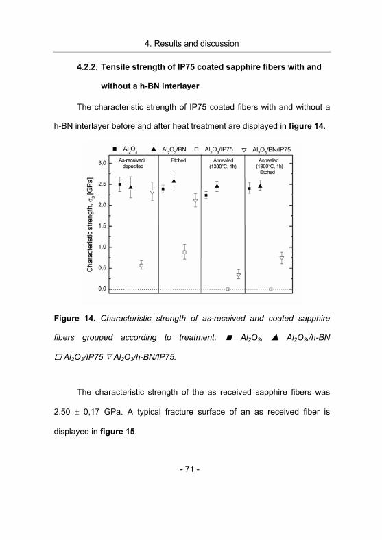
4. Results and discussion
- 71 -
4.2.2. Tensile strength of IP75 coated sapphire fibers with and
without a h-BN interlayer
The characteristic strength of IP75 coated fibers with and without a
h-BN interlayer before and after heat treatment are displayed in figure 14.
Figure 14. Characteristic strength of as-received and coated sapphire
fibers grouped according to treatment. � Al2O3, � Al2O3,/h-BN
� Al2O3/IP75 � Al2O3/h-BN/IP75.
The characteristic strength of the as received sapphire fibers was
2.50 � 0,17 GPa. A typical fracture surface of an as received fiber is
displayed in figure 15.
4. Results and discussion
- 72 -
Figure 15. Fracture surface of an as received fiber.
No large facets, steps or preferential crack direction can be
discerned. No significant change in �0 is detected after annealing and/or
etching of the as-received fibers. Similarly, no strength degradation of
fibers coated with only h-BN was measured before or after annealing.
Significant strength degradation was observed for the IP75 coated
fibers without a h-BN interlayer after the PVD process. Approximately 23%
(570 MPa) of the initial strength was retained for coated fibers and 35%
(880 MPa) with the coating etched away which indicates deposition
process induced damage of the fibers. No morphological changes were
detected on the fiber surface at the vicinity of the fracture surface within the
resolution of the SEM, and hence the strength degradation cannot be
explained by altered fiber surface morphology. The small but significant
increase in strength of etched fibers may be explained by the existence of
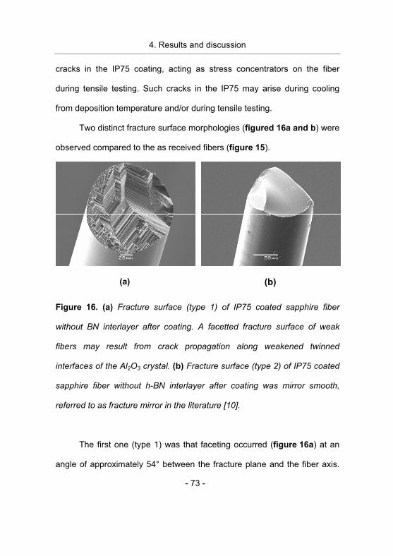
4. Results and discussion
- 73 -
cracks in the IP75 coating, acting as stress concentrators on the fiber
during tensile testing. Such cracks in the IP75 may arise during cooling
from deposition temperature and/or during tensile testing.
Two distinct fracture surface morphologies (figured 16a and b) were
observed compared to the as received fibers (figure 15).
(a) (b)
Figure 16. (a) Fracture surface (type 1) of IP75 coated sapphire fiber
without BN interlayer after coating. A facetted fracture surface of weak
fibers may result from crack propagation along weakened twinned
interfaces of the Al2O3 crystal. (b) Fracture surface (type 2) of IP75 coated
sapphire fiber without h-BN interlayer after coating was mirror smooth,
referred to as fracture mirror in the literature [10].
The first one (type 1) was that faceting occurred (figure 16a) at an
angle of approximately 54° between the fracture plane and the fiber axis.
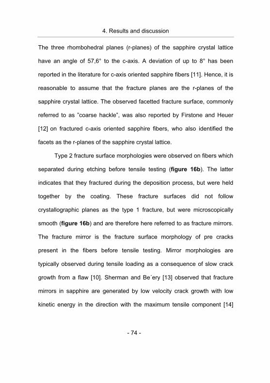
4. Results and discussion
- 74 -
The three rhombohedral planes (r-planes) of the sapphire crystal lattice
have an angle of 57,6° to the c-axis. A deviation of up to 8° has been
reported in the literature for c-axis oriented sapphire fibers [11]. Hence, it is
reasonable to assume that the fracture planes are the r-planes of the
sapphire crystal lattice. The observed facetted fracture surface, commonly
referred to as ”coarse hackle”, was also reported by Firstone and Heuer
[12] on fractured c-axis oriented sapphire fibers, who also identified the
facets as the r-planes of the sapphire crystal lattice.
Type 2 fracture surface morphologies were observed on fibers which
separated during etching before tensile testing (figure 16b). The latter
indicates that they fractured during the deposition process, but were held
together by the coating. These fracture surfaces did not follow
crystallographic planes as the type 1 fracture, but were microscopically
smooth (figure 16b) and are therefore here referred to as fracture mirrors.
The fracture mirror is the fracture surface morphology of pre cracks
present in the fibers before tensile testing. Mirror morphologies are
typically observed during tensile loading as a consequence of slow crack
growth from a flaw [10]. Sherman and Be´ery [13] observed that fracture
mirrors in sapphire are generated by low velocity crack growth with low
kinetic energy in the direction with the maximum tensile component [14]
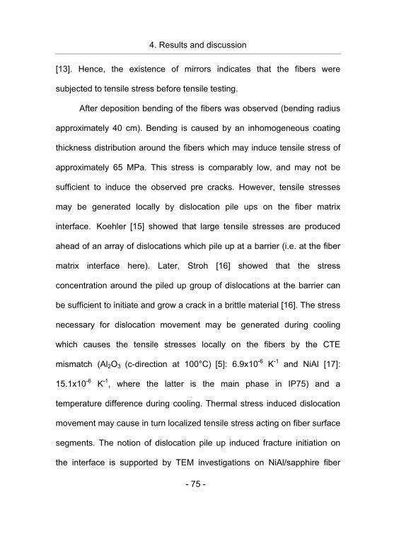
4. Results and discussion
- 75 -
[13]. Hence, the existence of mirrors indicates that the fibers were
subjected to tensile stress before tensile testing.
After deposition bending of the fibers was observed (bending radius
approximately 40 cm). Bending is caused by an inhomogeneous coating
thickness distribution around the fibers which may induce tensile stress of
approximately 65 MPa. This stress is comparably low, and may not be
sufficient to induce the observed pre cracks. However, tensile stresses
may be generated locally by dislocation pile ups on the fiber matrix
interface. Koehler [15] showed that large tensile stresses are produced
ahead of an array of dislocations which pile up at a barrier (i.e. at the fiber
matrix interface here). Later, Stroh [16] showed that the stress
concentration around the piled up group of dislocations at the barrier can
be sufficient to initiate and grow a crack in a brittle material [16]. The stress
necessary for dislocation movement may be generated during cooling
which causes the tensile stresses locally on the fibers by the CTE
mismatch (Al2O3 (c-direction at 100°C) [5]: 6.9x10⁻⁶ K-1 and NiAl [17]:
15.1x10⁻⁶ K-1, where the latter is the main phase in IP75) and a
temperature difference during cooling. Thermal stress induced dislocation
movement may cause in turn localized tensile stress acting on fiber surface
segments. The notion of dislocation pile up induced fracture initiation on
the interface is supported by TEM investigations on NiAl/sapphire fiber
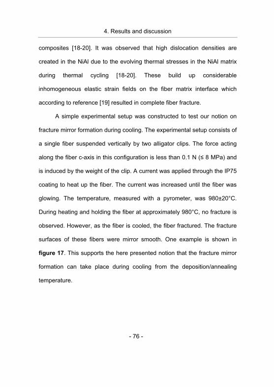
4. Results and discussion
- 76 -
composites [18-20]. It was observed that high dislocation densities are
created in the NiAl due to the evolving thermal stresses in the NiAl matrix
during thermal cycling [18-20]. These build up considerable
inhomogeneous elastic strain fields on the fiber matrix interface which
according to reference [19] resulted in complete fiber fracture.
A simple experimental setup was constructed to test our notion on
fracture mirror formation during cooling. The experimental setup consists of
a single fiber suspended vertically by two alligator clips. The force acting
along the fiber c-axis in this configuration is less than 0.1 N (� 8 MPa) and
is induced by the weight of the clip. A current was applied through the IP75
coating to heat up the fiber. The current was increased until the fiber was
glowing. The temperature, measured with a pyrometer, was 980±20°C.
During heating and holding the fiber at approximately 980°C, no fracture is
observed. However, as the fiber is cooled, the fiber fractured. The fracture
surfaces of these fibers were mirror smooth. One example is shown in
figure 17. This supports the here presented notion that the fracture mirror
formation can take place during cooling from the deposition/annealing
temperature.
4. Results and discussion
- 77 -
Figure 17. Fracture surface morphology of an IP75 coated sapphire fiber
without a BN interlayer that fractured during cooling after heating to 980°C.
Fracture surfaces exhibiting a combination of fracture mirror and
coarse hackle were also observed on fibers with degraded strength (figure
18).
Figure 18. Fracture surface (type 1 and 2) of IP75 coated sapphire fiber
without BN interlayer after tensile testing and subsequent etching.
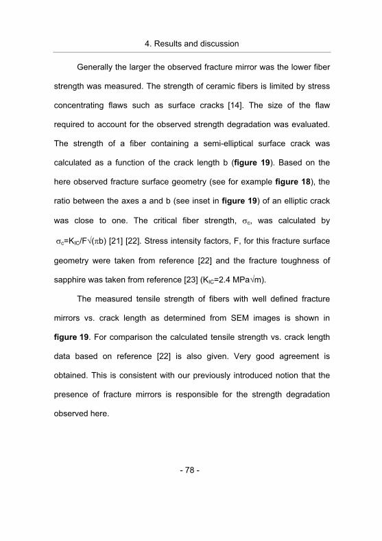
4. Results and discussion
- 78 -
Generally the larger the observed fracture mirror was the lower fiber
strength was measured. The strength of ceramic fibers is limited by stress
concentrating flaws such as surface cracks [14]. The size of the flaw
required to account for the observed strength degradation was evaluated.
The strength of a fiber containing a semi-elliptical surface crack was
calculated as a function of the crack length b (figure 19). Based on the
here observed fracture surface geometry (see for example figure 18), the
ratio between the axes a and b (see inset in figure 19) of an elliptic crack
was close to one. The critical fiber strength, �c, was calculated by
��c=KIC/F�(�b) [21] [22]. Stress intensity factors, F, for this fracture surface
geometry were taken from reference [22] and the fracture toughness of
sapphire was taken from reference [23] (KIC=2.4 MPa�m).
The measured tensile strength of fibers with well defined fracture
mirrors vs. crack length as determined from SEM images is shown in
figure 19. For comparison the calculated tensile strength vs. crack length
data based on reference [22] is also given. Very good agreement is
obtained. This is consistent with our previously introduced notion that the
presence of fracture mirrors is responsible for the strength degradation
observed here.
4. Results and discussion
- 79 -
Figure 19. Critical strength vs. crack length. A comparison between
calculations based on the fracture geometry shown in figure 18 and the
tensile test data.
In contrast to the fibers coated with only IP75, no strength
degradation was measured for fibers with a h-BN interlayer after the PVD
process. For these fibers no pronounced type 1 or 2 fracture surfaces were
discerned.
The simulation results (figure 20) show the compressive axial
thermal stress, �zz, that develops in a sapphire fiber deposited with IP75
with and without a h-BN interlayer along its c-axis at different
temperatures.
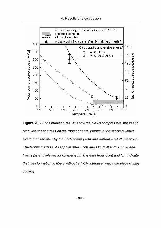
4. Results and discussion
- 80 -
Figure 20. FEM simulation results show the c-axis compressive stress and
resolved shear stress on the rhombohedral planes in the sapphire lattice
exerted on the fiber by the IP75 coating with and without a h-BN interlayer.
The twinning stress of sapphire after Scott and Orr. [24] and Schmid and
Harris [9] is displayed for comparison. The data from Scott and Orr indicate
that twin formation in fibers without a h-BN interlayer may take place during
cooling.
4. Results and discussion
- 81 -
Sputtered IP75 coatings develop a columnar structure [25] which
considerably differs from the cast IP75 microstructure [26]. It is reasonable
to assume that lower thermal residual stresses develop due to the under-
dense microstructure. The simulation results may therefore be considered
as an upper boundary of thermal stresses that may develop during cooling.
For comparison, the compressive strength of sapphire along the c-axis is
given, which was established experimentally by Scott and Orr [24]. They
reported that twin formation on the r-planes of the sapphire crystal limits its
c-axis compressive strength. Hence, the resolved shear stress on the
r-planes is also displayed in figure 20, which is equal to the c-axis
compressive stress multiplied by the Schmid factor of 0.452 [9]. The
measured deviation of the crystal c-axis angle to the fiber axis discussed
earlier implies up to 5 % difference in resolved shear stress on the
r-planes, and therefore the resolved shear stress on specific r-planes may
be even higher than the values displayed here, implying a lower
compressive strength of the fibers. When two twins intersect, atoms at the
intersection are shared by two differently oriented twins, producing large
stress concentrations at the intersection which may lead to fracture. This
has been identified as the reason why the compressive strength is equal to
the twinning stress [27, 9, 24]. In the work of Scott and Orr [24], sapphire
rods (9 mm long and 3 mm across) were tested in compression at
4. Results and discussion
- 82 -
temperatures ranging from 623 to 1373 K. It was observed that the twin
formation stress of samples with ground surfaces exhibited strong
temperature dependence, whereas polished samples exhibited an
athermal behavior (figure 20), indicating that the twin formation stress and
hence the compressive strength depends on the surface conditions, which
has also been observed earlier by Bertolot and Scott [27]. It is assumed
that a twin forms at a pre existing twin nucleus or local stress concentration
sites originating from surface damage induced during cutting, polishing or
grinding the specimen [27, 24]. Schmid and Harris [9] measured a strong
temperature dependence of the twin formation with polished samples,
similar to the ground samples by Scott and Orr. The data from Schmid and
Harris are also plotted in figure 20 for comparison. They did not attribute
the twin formation stress to surface finish. However, as displayed in
figure 20, the temperature region where Scott and Orr established a
dependence on surface finish (between 773 and 900 K), contains only one
data point in the work of Schmid and Harris [9]. The resolved shear stress
on the r-planes for twin formation by Scott and Orr [24], was as low as
12.6 � 6 MPa for polished samples above 773 K (figure 20). Based on
these literature values, the compressive stress on fibers without a h-BN
interlayer is exceeded by more than 100% during cooling from deposition
temperature (figure 20) and twinning has to be expected. The interface
4. Results and discussion
- 83 -
between the twinned and untwinned crystal is weaker than the untwinned
crystal itself [28, 29], leading to a decrease in tensile strength. This is
consistent with the lower strength value measured for these fibers. The
fracture in a twinned sapphire crystal tends to follow the weak interface
[28, 29] which is consistent with the coarse hackle fracture surface
morphology observed here. According to the discussion above fibers with a
combination of type 1 and 2 fracture surfaces may contain r-plane twins as
well as fracture mirrors before testing.
According to the simulation results, the h-BN interlayer decreases
the developing thermal stresses below the twin formation stress during
cooling (figure 20), which is consistent with the observed fracture surface
morphologies as well as tensile strength results discussed earlier.
During annealing, IP75 coated fibers without a h-BN interlayer
fractured and tensile testing was therefore not possible. This has also been
observed on fibers coated with NiAl and may be due to thermally induced
stress causing fracture of the sapphire [30]. It is likely that the same
mechanism is at least in part responsible for the strength degradation of
these annealed fibers as for the “as deposited fibers” discussed earlier.
This is supported by the fracture surface analysis, where large smooth
fracture surfaces, i.e. mirrors, were identified, similar to the one displayed
in figures 16b and 17. The annealed and etched fiber surfaces also
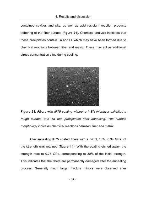
4. Results and discussion
- 84 -
contained cavities and pits, as well as acid resistant reaction products
adhering to the fiber surface (figure 21). Chemical analysis indicates that
these precipitates contain Ta and O, which may have been formed due to
chemical reactions between fiber and matrix. These may act as additional
stress concentration sites during cooling.
Figure 21. Fibers with IP75 coating without a h-BN interlayer exhibited a
rough surface with Ta rich precipitates after annealing. The surface
morphology indicates chemical reactions between fiber and matrix.
After annealing IP75 coated fibers with a h-BN, 13% (0.34 GPa) of
the strength was retained (figure 14). With the coating etched away, the
strength rose to 0,75 GPa, corresponding to 30% of the initial strength.
This indicates that the fibers are permanently damaged after the annealing
process. Generally much larger fracture mirrors were observed after
4. Results and discussion
- 85 -
annealing than on the IP75 coated fibers after deposition discussed earlier
(figure 22a-b, where the frame in fig 22a marks the crack initiation site,
displayed in 22b). This is consistent with the comparably low fiber strength
measured.
An altered fiber surface morphology was observed at the vicinity of
the fracture surfaces where the cracks were initiated (figure 22b). Also
ridges (figure 22c) and grooves (figure 22d) were observed meandering
on the fiber surface, which may contribute to strength degradation.
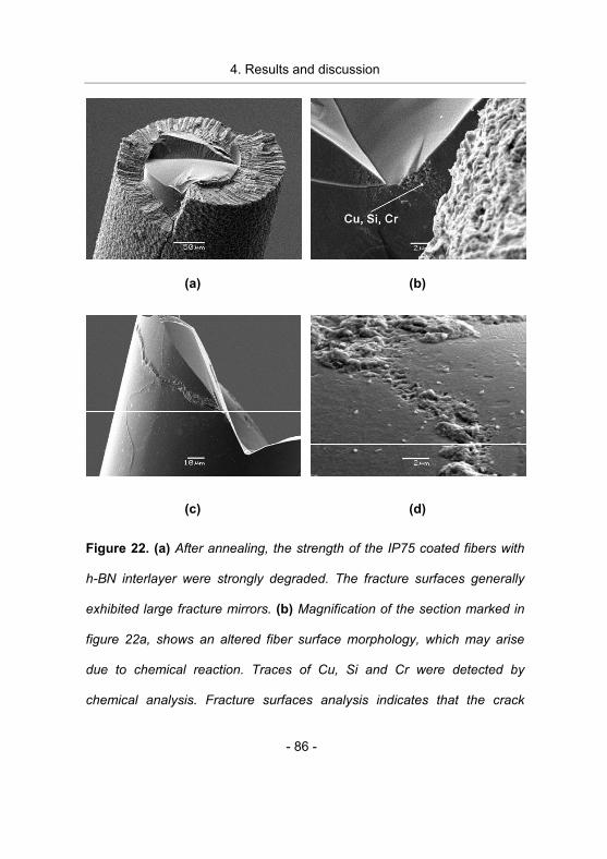
4. Results and discussion
- 86 -
(a) (b)
(c) (d)
Figure 22. (a) After annealing, the strength of the IP75 coated fibers with
h-BN interlayer were strongly degraded. The fracture surfaces generally
exhibited large fracture mirrors. (b) Magnification of the section marked in
figure 22a, shows an altered fiber surface morphology, which may arise
due to chemical reaction. Traces of Cu, Si and Cr were detected by
chemical analysis. Fracture surfaces analysis indicates that the crack
4. Results and discussion
- 87 -
initiates at these sites. (c) Ridges and (d) grooves with traces of mainly Si
and Cr were observed on the fiber surface after etching of the annealed
IP75/BN coated fibers. These may form due to chemical reactions with the
fiber through cracks in the h-BN interlayer.
Traces of mainly Si, but also Cr and Cu, were detected by chemical
analysis on the ridges and in the groves, indicating that the morphological
changes may be due to chemical reactions on the fiber surface during
annealing. The meandering pattern indicates that these reactions may take
place through cracks in the h-BN interlayer, which may form during the
annealing process as a consequence of the thermal stress due to
differences in CTE between the constituents of the composite and/or due
to thermally induced pore formation [31]. The deposited h-BN interlayers
have 89% of the theoretical density [32]. Densification induced stress at
the composite fabrication temperature of 1300°C due to crystallization of
the turbostratic structure [2] may also lead to the observed cracking of the
BN interlayer. Cu most likely originates from the Cu clamps used to fasten
the IP75 sputtering target. Si may be introduced in the IP75 during the
casting process [33] and forms SiO with �-Al2O3 already at T >925°C [34].
Al2SiO5 is identified by X-ray diffraction in the cast IP75 alloy [26], and
hence Si is present in the alloy. Cr which is an alloying element in IP75 has
4. Results and discussion
- 88 -
been observed to react with �-Al2O3 at 1250°C [35] (compared to 1300°C
used here). Hence the roughened surface morphology may be caused by
chemical reactions between �-Al2O3 fiber and Si impurities and/or Cr at the
annealing temperatures of 1300°C. The altered fiber surface morphology
may act as a stress concentration site, leading to fiber strength
degradation. The fracture mirror formation in fibers with a BN interlayer
after annealing may happen at locally tensile strained surface segments
due to dislocation pile up [18, 15, 16, 19, 20] and or inhomogeneous NiAl
coating thickness along the fiber as discussed above. Additionally mirrors
may also form at stress concentration sites on the surface during loading,
similarly to a notched specimen. This was observed in the work of
Sherman [13], where the introduction of a notch in the sapphire specimen
resulted in the formation of a large fracture mirror during loading. Stresses
sufficient for propagation of a fracture mirror may also arise at chemical
reaction sites in the fiber due to volume changes associated with the
reaction.
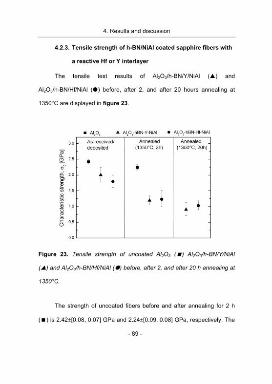
4. Results and discussion
- 89 -
4.2.3. Tensile strength of h-BN/NiAl coated sapphire fibers with
a reactive Hf or Y interlayer
The tensile test results of Al2O3/h-BN/Y/NiAl (�) and
Al2O3/h-BN/Hf/NiAl (�) before, after 2, and after 20 hours annealing at
1350°C are displayed in figure 23.
Figure 23. Tensile strength of uncoated Al2O3 (�) Al2O3/h-BN/Y/NiAl
(�) and Al2O3/h-BN/Hf/NiAl (�) before, after 2, and after 20 h annealing at
1350°C.
The strength of uncoated fibers before and after annealing for 2 h
(�) is 2.42�[0.08, 0.07] GPa and 2.24�[0.09, 0.08] GPa, respectively. The
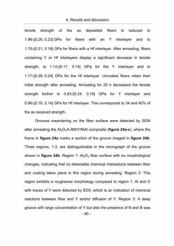
4. Results and discussion
- 90 -
tensile strength of the as deposited fibers is reduced to
1.96�[0.26, 0.23] GPa for fibers with an Y interlayer and to
1.75�[0.21, 0.19] GPa for fibers with a Hf interlayer. After annealing, fibers
containing Y or Hf interlayers display a significant decrease in tensile
strength, to 1.13�[0.17, 0.14] GPa for the Y interlayer and to
1.17�[0.28, 0.24] GPa for the Hf interlayer. Uncoated fibers retain their
initial strength after annealing. Annealing for 20 h decreased the tensile
strength further to 0.83�[0.24, 0.19] GPa for Y interlayer and
0.96�[0.16, 0.14] GPa for Hf interlayer. This corresponds to 34 and 40% of
the as received strength.
Grooves meandering on the fiber surface were detected by SEM
after annealing the Al2O3/h-BN/Y/NiAl composite (figure 24a-c), where the
frame in figure 24a marks a section of the groove imaged in figure 24b.
Three regions, 1-3, are distinguishable in the micrograph of the groove
shown in figure 24b. Region 1: Al2O3 fiber surface with no morphological
changes, indicating that no detectable chemical interactions between fiber
and coating takes place in this region during annealing. Region 2: This
region exhibits a roughened morphology compared to region 1. Al and O
with traces of Y were detected by EDX, which is an indication of chemical
reactions between fiber and Y and/or diffusion of Y. Region 3: A deep
groove with large concentration of Y but also the presence of N and B was
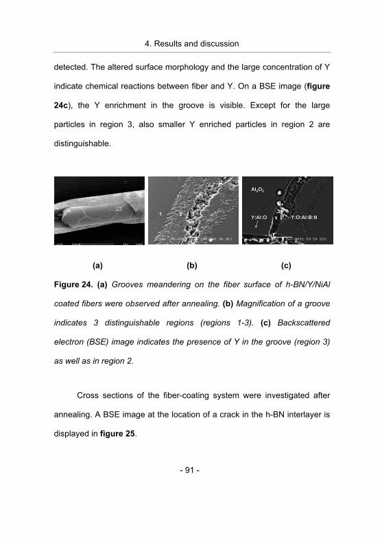
4. Results and discussion
- 91 -
detected. The altered surface morphology and the large concentration of Y
indicate chemical reactions between fiber and Y. On a BSE image (figure
24c), the Y enrichment in the groove is visible. Except for the large
particles in region 3, also smaller Y enriched particles in region 2 are
distinguishable.
(a) (b) (c)
Figure 24. (a) Grooves meandering on the fiber surface of h-BN/Y/NiAl
coated fibers were observed after annealing. (b) Magnification of a groove
indicates 3 distinguishable regions (regions 1-3). (c) Backscattered
electron (BSE) image indicates the presence of Y in the groove (region 3)
as well as in region 2.
Cross sections of the fiber-coating system were investigated after
annealing. A BSE image at the location of a crack in the h-BN interlayer is
displayed in figure 25.
4. Results and discussion
- 92 -
Figure 25. Backscattered electron (BSE) image of the h-BN/Y/NiAl coating
on the Al2O3 fiber after annealing at the position of a crack in the h-BN
interlayer. The image suggests that chemical reactions take place through
cracks in the h-BN interlayer.
Here, the fiber and the different layers are visible, as well as a pore
in the NiAl matrix. The chemical analysis indicates that the Y interlayer
contains O, Al, and N, which is consistent with the chemical analysis on the
FIB cross sections discussed earlier. The Al content and the local growth
of the Y interlayer around the crack in combination with the pore formation
may be due to Al diffusion from the NiAl into the Y interlayer. The crack in
the h-BN interlayer supplies a surface diffusion path from the Y rich layer to
the Al2O3, and since Y3Al5O12 is more stable than �-Al2O3 [36], the groove
may form by chemical reaction between the fiber and Y.
4. Results and discussion
- 93 -
As discussed earlier, cracks in the h-BN interlayer may be created
during cooling after deposition or after the annealing treatment, due to the
development of thermal stresses arising from extensive differences in the
CTE´s between the Al2O3 fiber (CTE=6�10-6 K-1) [5], h-BN
(CTE=1.1-8.6�10-6 K-1) [37] and NiAl (CTE=15�10-6 K-1) [17].
The fracture surfaces of fibers containing Y or Hf interlayer were
examined with SEM and EDX-Electron Probe Micro Analysis (EPMA), in
order to detect the fracture initiation sites. On fibers with a Hf interlayer a
groove in the h-BN interlayer with traces of Hf was detected at the position
of fracture initiation (figure 26a-b), which may be a result of reaction
between Hf and h-BN. This is consistent with the formation of HfB2 and
HfN as observed by XRD. At the corresponding location on the fiber
surface of the etched fiber, a ridge was detected (figure 26c).
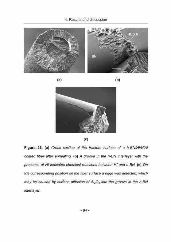
4. Results and discussion
- 94 -
(a) (b)
(c)
Figure 26. (a) Cross section of the fracture surface of a h-BN/Hf/NiAl
coated fiber after annealing. (b) A groove in the h-BN interlayer with the
presence of Hf indicates chemical reactions between Hf and h-BN. (c) On
the corresponding position on the fiber surface a ridge was detected, which
may be caused by surface diffusion of Al2O3 into the groove in the h-BN
interlayer.
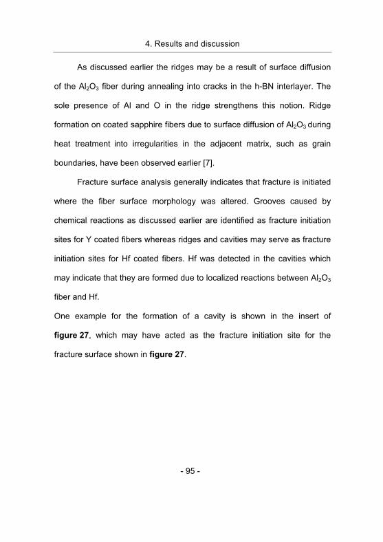
4. Results and discussion
- 95 -
As discussed earlier the ridges may be a result of surface diffusion
of the Al2O3 fiber during annealing into cracks in the h-BN interlayer. The
sole presence of Al and O in the ridge strengthens this notion. Ridge
formation on coated sapphire fibers due to surface diffusion of Al2O3 during
heat treatment into irregularities in the adjacent matrix, such as grain
boundaries, have been observed earlier [7].
Fracture surface analysis generally indicates that fracture is initiated
where the fiber surface morphology was altered. Grooves caused by
chemical reactions as discussed earlier are identified as fracture initiation
sites for Y coated fibers whereas ridges and cavities may serve as fracture
initiation sites for Hf coated fibers. Hf was detected in the cavities which
may indicate that they are formed due to localized reactions between Al2O3
fiber and Hf.
One example for the formation of a cavity is shown in the insert of
figure 27, which may have acted as the fracture initiation site for the
fracture surface shown in figure 27.
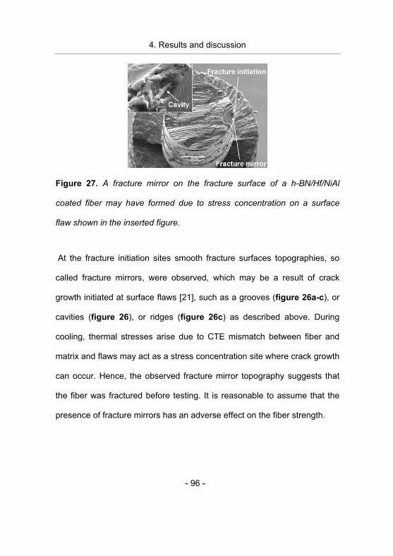
4. Results and discussion
- 96 -
Figure 27. A fracture mirror on the fracture surface of a h-BN/Hf/NiAl
coated fiber may have formed due to stress concentration on a surface
flaw shown in the inserted figure.
At the fracture initiation sites smooth fracture surfaces topographies, so
called fracture mirrors, were observed, which may be a result of crack
growth initiated at surface flaws [21], such as a grooves (figure 26a-c), or
cavities (figure 26), or ridges (figure 26c) as described above. During
cooling, thermal stresses arise due to CTE mismatch between fiber and
matrix and flaws may act as a stress concentration site where crack growth
can occur. Hence, the observed fracture mirror topography suggests that
the fiber was fractured before testing. It is reasonable to assume that the
presence of fracture mirrors has an adverse effect on the fiber strength.
4. Results and discussion
- 97 -
No significant difference in size or morphology of the surface
morphological features was noticed between fibers annealed for 2 and
20 h, which is consistent with the similar strength values measured.
According to the results presented here, the largest individual
challenge for maintaining high fiber strength is eliminating the thermal
stress induced fiber damage. We have shown that despite of a substantial
lowering of thermal stresses by weakening the fiber matrix bond with a
h-BN interlayer, the fiber strength is degraded due to thermal stress
induced fracture mirror formation at surface flaws. Possibly the strength
degradation related fiber damage can be prevented by lowering the
thermal stresses further e.g. by increasing the fiber volume fraction in the
IMC [8] and/or by modifying the fracture properties of the reinforcing fiber
and by avoiding chemical reactions on the fiber surface by the choice of
matrix and interlayer material.
4. Results and discussion
- 98 -
List of references
[1] Intermetallic compounds, Vol. 2, D. B. Miracle, (John Wiley &
Sons Ltd, 1994).
[2] Interface structure, chemistry and properties of NiAl
composites fabricated from matrix-coated single-crystalline Al2O3 fibres (sapphire) with and without an hBN interlayer,
W. Hu, T. Weirich, B. Hallstedt, H. Chen, Y. Zhong, and G. Gottstein,
Acta Materialia 54 (2006) 2473.
[3] Deformation behaviour of intermetallic NiAl-Ta alloys with
strengthening Laves phase for high-temperature applications III. Effects of alloying with Cr, B. Zeumer and G. Sauthoff,
Intermetallics 6 (1998) 451.
[4] Hydrogen uptake in alumina thin films synthesized from an
aluminum plasma stream in an oxygen ambient, J. M. Schneider,
A. Anders, B. Hjorvarsson, I. Petrov, K. Macak, U. Helmersson, and
J. E. Sundgren, Applied Physics Letters 74 (1999) 200.
[5] Data sheet for c-axis oriented sapphire fibers (www.photran.com)
[6] Al2O3 Fiber Strength Degradation in Metal and Intermetallic Matrix Composites, S. L. Draper and I. E. Locci, Journal of
Materials Research 9 (1994) 1397.
[7] Effects of Composite Processing on the Strength of Sapphire
Fiber-Reinforced Composites, J. B. Davis, J. Yang, and
A. G. Evans, Acta Metallurgica Et Materialia 43 (1995) 259.
[8] Thermal residual stress (TRS) analysis in continuous Al2O3 fiber
reinforced NiAl composite, H. Chen, W. Hu, A. Atiser, Y. Zhong,
and G. Gottstein, International journal of materials research 97
(2006) 10.
4. Results and discussion
- 99 -
[9] Effects of crystal orientation and temperature on the strength of
sapphire, F. Schmid and D. C. Harris, Journal of the American
Ceramic Society 81 (1998) 885.
[10] Observing and interpreting fracture surface topography, D. Hull,
(Cambridge University Press, Cambridge, 1999).
[11] Slow Crack-Growth in Sapphire Fibers at 800-Degrees to 1500-Degrees-C, S. A. Newcomb and R. E. Tressler, Journal of the
American Ceramic Society 76 (1993) 2505.
[12] Creep Deformation of 0 Degree Sapphire, R. F. Firestone and
A. H. Heuer, Journal of the American Ceramic Society 59 (1976) 24.
[13] Fracture mechanisms of sapphire under bending, D. Sherman
and I. Be'ery, Journal of Materials Science 35 (2000) 1283.
[14] Fracture of Brittle Solids-Second Edition, B. Lawn, (Cambridge
University Press, 1975).
[15] The Production of Large Tensile Stresses by Dislocations, J. S.
Koehler, Physical Review 85 (1952) 480.
[16] The Formation of Cracks as a Result of Plastic Flow, A. N. Stroh,
Proceedings of the Royal Society of London Series A-Mathematical
and Physical Sciences 223 (1954) 404.
[17] Overview No.104 - The Physical and Mechanical-Properties of NiAl, D. B. Miracle, Acta Metallurgica Et Materialia 41 (1993) 649.
[18] Interfaces in Metal-Matrix and Intermetallic-Matrix Composites,
R. J. Arsenault, Composites 25 (1994) 540.
[19] Dislocations in continuous filament reinforced W/NiAl and Al2O3/NiAl composites, L. Wang, K. Xu, R. R. Bowman, and
R. J. Arsenault, Metallurgical and Materials Transactions A-Physical
Metallurgy and Materials Science 28 (1997) 2755.
4. Results and discussion
- 100 -
[20] Interfaces in Continuous Filament-Reinforced Al2O3/NiAl
Composites, L. Wang, K. Xu, R. R. Bowman, and R. J. Arsenault,
Metallurgical and Materials Transactions A-Physical Metallurgy and
Materials Science 26 (1995) 897.
[21] Effect of flaw shape on strength of ceramics, G. K. Bansal,
Journal of the American Ceramic Society 59 (1976) 87.
[22] Stress intensity factors handbook, Vol. 2, Y. Murakami,
Pergamon press (1986) 659.
[23] Fracture Toughness of Quartz and Sapphire Single Crystals at Room Temperature, M. Iwasa, T. Ueno, and R. C. Bradt, Journal of
the Society of Materials Science, Japan 30 (1981) 1001.
[24] Rhombohedral Twinning in Alumina, W. D. Scott and K. K. Orr,
Journal of the American Ceramic Society 66 (1983) 27.
[25] Long fibre reinforced NiAl: High temperature material for
turbine blades, M. Rosefort, C. Dahmen, A. Buhrig-Polaczek,
W. P. Hu, H. Chen, Y. L. Zhong, G. Gottstein, D. E. Hajas, and
J. M. Schneider, Advanced Engineering Materials 8 (2006) 730.
[26] Microstructure and mechanical properties of continuous Al2O3
fibre reinforced Ni45Al45Cr7.5Ta2.5 alloy (IP75) matrix composites,
Y. Zhong, D. E. Hajas, W. Hu, H. Chen, and G. Gottstein,
Philosophical Magazine A 87 (2007) 1019
[27] Compressive Creep of Al2O3 Single Crystals, R. l. Bertolot and
W. D. Scott, Journal of the American Ceramic Society 54 (1971)
286.
[28] Mechanical Behavior of Sapphire, H. Conrad, Journal of the
American Ceramic Society 48 (1965) 195.
4. Results and discussion
- 101 -
[29] Fracture and Twinning in Sapphire (Alpha-Al203) Crystals,
E. Stofel and H. Conrad, Transactions of the Metallurgical Society of
AIME 227 (1963) 1053.
[30] Effect of a BN interlayer on the tensile strength of NiAl coated
sapphire fibers, D. E. Hajas, S. Kyrsta, and J. M. Schneider,
Scripta Materialia 55 (2006) 219.
[31] Effect of a boron nitride interphase that debonds between the
interphase and the matrix in SiC/SiC composites, G. N.
Morscher, H. M. Yun, J. A. DiCarlo, and L. Thomas-Ogbuji, Journal
of the American Ceramic Society 87 (2004) 104.
[32] Constitution and deposition mechanisms of hexagonal boron nitride formed by CVD from trimethylborazine
A. Jörg, E. Zimmermann, M. Schierling, R. Cremer, and
D. Neuschütz, in CVD XIV and Euro CVD-11, The Electrochemical
Society (Pennington, USA, 1997).
[33] Production-scale processing of a new intermetallic NiAl-Ta-Cr
alloy for high-temperature application Part I. Production of
master alloy remelt ingots and investment casting of combustor liner model panels, M. Palm, J. Preuhs, and G. Sauthoff, Journal of
Materials Processing Technology 136 (2003) 105.
[34] Silicon-on-Sapphire Epitaxy by Vacuum Sublimation - Leed-
Auger Studies and Electronic Properties of Films, C. C. Chang,
Journal of Vacuum Science & Technology 8 (1971) 500.
[35] Effect of Cr on Interfacial Interaction and Wetting Mechanisms in Ni-Alloy Alumina Systems, P. Kritsalis, V. Merlin, L. Coudurier,
and N. Eustathopoulos, Acta Metallurgica Et Materialia 40 (1992)
1167.
4. Results and discussion
- 102 -
[36] Reaction paths in the system Al2O3-hBN-Y, K. Reichert,
O. Oreshina, R. Cremer, and D. Neuschütz, Applied Surface
Science 179 (2001) 138.
[37] Hexagonal Boron Nitride: Fabrication, Properties and
Applications, A. Lipp, K. A. Schwetz, and K. Hunold, Journal of the
European Ceramic Society 5 (1989) 3.
5. Conclusions
- 103 -
5. Conclusions
One way to increase the efficiency of a gas turbine is by increasing
the combustion zone temperature. For this new materials are needed that
can withstand the increase in temperature without degradation of their
mechanical properties. Sapphire fiber reinforced NiAl is of special interest
for the combustion zone turbine blades. However, experimental results
have shown that the strength of the fibers is reduced during composite
fabrication. The goal of this thesis was to identify strength degradation
relevant mechanisms active between �-Al2O3 fibers and the surrounding
matrix or interlayer, in order to minimize the strength degradation during
production of IMC’s in the future. These data are important for formulating
future strategies for the production of IMC´s.
Strength degradation mechanisms of NiAl or IP75 coated fibers with
and without an Y (or Hf) and/or h-BN interlayer have been assessed.
Fracture- and fiber- surfaces after tensile testing were evaluated by
microscopy and chemical analysis. The effect of temperature during
diffusion bonding as well as the presence of an interlayer on the tensile
strength has been studied.
5. Conclusions
- 104 -
Strength degradation was measured for IP75 coated fibers without a
h-BN interlayer after deposition, indicating the introduction of deposition
process related damage. This notion is supported by the observation of
fracture mirrors and coarse hackle fracture surface morphologies. The
coarse hackles indicate twinning of the rhombohedral Al2O3 crystal planes,
which was predicted by simulation results as a consequence of the
evolving stress during cooling after deposition. Surface flaws in
combination with thermal stress on the fiber matrix interface may cause
local stress concentrations on the fiber, which may be responsible for the
fracture mirror formation.
Tensile testing of annealed NiAl or IP75 coated fibers without a h-BN
interlayer was not possible due to fracturing of the fibers. Large fracture
mirrors were observed, which indicates that thermal stress induced fracture
mirror formation during cooling from composite fabrication temperature is
the main strength degradation mechanism after annealing, when no h-BN
interlayer is present.
IP75 or NiAl coated fibers containing a h-BN/Y (or Hf) or a h-BN
interlayer degraded their strength after annealing. Fracture mirrors with
altered fiber surface morphology at the vicinity of the fracture surface
caused by Al2O3 surface diffusion into cracks or irregularities in the
5. Conclusions
- 105 -
interlayer material as well as chemical reactions between fiber and matrix
or interlayer elements (Cr, Y or Hf) or impurities (Si) were observed. The
fracture mirror formation may be a consequence of the developing thermal
stresses at the sites with altered surface morphology causing fiber strength
degradation.
Based on these observations the following strength degradation
relevant mechanisms for coated sapphire fibers with or without an
interlayer are proposed: Twinning of the rhombohedral plane (r-plane) of
the sapphire crystal as a consequence of the evolving thermal stress
during cooling. Chemical reactions between fiber and matrix material
and/or impurities and surface diffusion of Al2O3 into irregularities in the
adjacent matrix material like cracks in the h-BN interlayer which both lead
to altering of the fiber surface morphology. In combination with the evolving
thermal stress during cooling, fracture mirror formation at the surface flaws
takes place, degrading the fiber strength.
In this work the fiber strength degradation mechanisms active during
individual process steps are identified. The significance of thermal stress
induced fiber damage is emphasized and it is concluded that the
elimination or a significant reduction thereof is the largest challenge which
5. Conclusions
- 106 -
has to be addressed to explore the strengthening potential of sapphire
fibers for IMC´s in the future.
Based on the results presented here, a strategy for obtaining high
strength IMC´s in the future is compiled. It is suggested that the strength
degradation may be avoided or minimized by: lowering the thermal stress,
by increasing the fiber volume fraction, and/or by using a ductile interlayer.
6. Future work
- 107 -
6. Future work
In this work it has been concluded that a significant reduction or
elimination of thermal stress induced fiber damage is the largest challenge
which has to be addressed in order to make use of the strengthening
potential of sapphire fibers for IMC´s in the future. It is suggested that the
strength degradation may be avoided or minimized by: i) lowering the thermal
stresses, ii) modifying the fracture and twinning properties of the
reinforcing fiber and/or iii) inhibiting the altering of the fiber surface
morphology due to chemical reactions or diffusion into irregularities in the
surrounding matrix or interlayer material.
Thermal stresses can be lowered by increasing the fiber volume
fraction in the IMC [1] or by introducing a damage tolerant interlayer
referred to as compliant interlayer in the literature [2], which
accommodates stress by yielding. Such a ductile interlayer also inhibits
crack formation on the interface during thermal cycling and impedes crack
propagation from the matrix into the fiber [2]. An example for such an
interlayer may be V2AlC [3].
The twin formation stress in sapphire can be altered by the addition
of dopants. It has been observed that the twinning stress of sapphire is
increased 3 fold by addition of Ti to the Al2O3 [4]. This is explained by
6. Future work
- 108 -
creation of stacking faults on the twin planes, which makes twin
propagation more difficult [4]. The effect of addition of other elements on
the fracture and twinning properties has not been investigated and may be
aim of future investigations. However, collaboration with the fiber
manufacturer is needed. The fiber properties may also be altered by
replacing the sapphire fiber with other another fiber material. Several
commercial ceramic fibers exist, like SiC fibers (e.g. SCS6 by Specialty
materials inc.) as well as poly-crystalline Al2O3 fibers (e.g. Nextel series by
3M) which both have been developed for high temperature applications [2].
The SCS6 fiber is of special interest due to its excellent high temperature
strength, > 3 GPa, at 1000°C, which is approximately three times higher
than the strength of the sapphire fibers used here.
SiC fibers have been incorporated in several matrix materials such
as: NiAl [5], FeAl [6] and TiAl [7] and TiAlNb [8] [9]. However, from the
literature it can be learned that chemical reactions between fiber and
matrix has limited its use. In order to utilize SiC as reinforcing fibers, these
chemical reactions have to be inhibited. This could be achieved by
introducing a chemically stable interlayer between fiber and matrix which
should also be ductile as discussed earlier. Ductile interlayers like Mo and
Nb have been investigated. However, chemical stability is not achieved for
these interlayers [2].
6. Future work
- 109 -
By reviewing the reaction products reported in the literature, it is
possible to identify reaction products which possess properties that may be
suited as interlayer. For instance it has been reported in the literature that
Ti3SiC2 forms as a reaction product between a TiAl and SiC, and is hence
chemically stable with SiC. This is also supported by the quaternary
Ti-Si-Al-C phase diagram, where a “tie line” exists between SiC and
Ti3SiC2 up to >1700°C [10]. Ti3SiC2 belongs to a group of materials called
MAX phases and which are known to possess some ductility at room
temperature [11]. The chemical stability in combination with ductility makes
this phase interesting as interlayer material. Ti3SiC2 can be deposited by
magnetron sputtering [12]. Initial growth of a TiCx interlayer was observed
on both MgO and Al2O3 substrates. However, growth characteristics of
Ti3SiC2 on SiC substrate have still not been investigated and can be the
scope of future investigation. Also the chemical stability between NiAl and
Ti3SiC2 remains to be investigated.
Deposition of the above discussed interlayers and chemical stability
investigations should be the primary scope of future work, followed by
assessment of strength degradation mechanisms using the methodology
presented in this thesis.
6. Future work
- 110 -
List of references
[1] Thermal residual stress (TRS) analysis in continuous Al2O3 fiber
reinforced NiAl composite, H. Chen, W. Hu, A. Atiser, Y. Zhong,
and G. Gottstein, International journal of materials research 97
(2006) 10.
[2] Intermetallic Matrix Composites III, Vol. 350, A. K. Misra, edited
by R. R. Bowman. J.A. Graves, J.J. Lewandowski (Materials
Research Society, San Francisco, 1994) 73.
[3] Tensile strength of NiAl coated sapphire fibers with a V2AlC
interlayer, G. Gebhardt, D. E. Hajas, B. Cappi, R. Telle, and
J. M. Schneider, Submitted for publication (January 2008).
[4] The effect of titanium doping on the high-temperature
rhombohedral twinning of sapphire, E. Savrun, W. D. Scott, and
D. C. Harris, Journal of Materials Science 36 (2001) 2295.
[5] Deposition, Characterization, Thermochemical Compatibility
and Failure Analysis of Multilayer Coated Silicon-Carbide Fiber-Reinforced Metal-Matrix Composites, R. S. Rastogi and
K. Pourrezaei, Journal of Materials Processing Technology 43
(1994) 89.
[6] Compatibility of Fe-40a1 with Various Fibers, S. L. Draper,
D. J. Gaydosh, M. V. Nathal, and A. K. Misra, Journal of Materials
Research 5 (1990) 1976.
[7] Reaction Zone Microstructure in a Ti3Al + Nb/SiC Composite,
S. F. Baumann, P. K. Brindley, and S. D. Smith, Metallurgical
Transactions a-Physical Metallurgy and Materials Science 21 (1990)
1559.
6. Future work
- 111 -
[8] Interface Control and Design for Sic Fiber-Reinforced Titanium
Aluminide Composites, H. P. Chiu, S. M. Jeng, and J. M. Yang,
Journal of Materials Research 8 (1993) 2040.
[9] Effect of Fiber Coating on the Mechanical-Behavior of SiC
Fiber-Reinforced Titanium Aluminide Composites, S. M. Jeng,
J. M. Yang, and J. A. Graves, Journal of Materials Research 8
(1993) 905.
[10] Phase equilibria at 1000 degrees C in the Al-C-Si-Ti quaternary
system: an experimental approach, J. C. Viala, N. Peillon,
F. Bosselet, and J. Bouix, Materials Science and Engineering A-
Structural Materials Properties Microstructure and Processing 229
(1997) 95.
[11] The M(N+1)AX(N) phases: A new class of solids; Thermodynamically stable nanolaminates, M. W. Barsoum,
Progress in Solid State Chemistry 28 (2000) 201.
[12] Growth of Ti3SiC2 thin films by elemental target magnetron sputtering, J. Emmerlich, H. Hogberg, S. Sasvari, P. O. A. Persson,
L. Hultman, J. P. Palmquist, U. Jansson, J. M. Molina-Aldareguia,
and Z. Czigany, Journal of Applied Physics 96 (2004) 4817.
Curriculum Vitae
David Hajas
Passstrasse 99 52070 Aachen E-Mail: [email protected] Persönliche Daten geboren am 11.06.1976 in Jönköping, Schweden Nationatilität: schwedisch Familienstand: verheiratet, ein Kind Berufstätigkeit 06/2006 – heute Leiter der Arbeitsgruppe für Werkstoffcharakterisierung,
Lehrstuhl für Werkstoffchemie der RWTH Aachen, Deutschland 10/2002 – heute Wissenschaftlicher Mitarbeiter, Lehrstuhl für Werkstoffchemie der
RWTH Aachen, Deutschland 01/2001 – 12/2001 Laborbetreuung, Institut für Physik, „Linköpings Universitet“,
Linköping, Schweden 06/1998 – 08/1998 Lehrer, „Erik Dahlbergsgymnasiet“, Jönköping, Schweden
- Unterricht in Mathemathik und Physik (Sommerschule) 01/1998 – 12/1998 Vorsitzender der Studienrichtungsvertretung (SNOrdf), „Linköpings Universitet“, Linköping, Schweden
08/1995 – 06/1996 Lehrhilfe in Mathemathik, Physik, Chemie und Biologie, „Per
Brahegymnasiet“ und „Junedahlskolan“, Jönköping, Schweden
Ausbildung 10/2002 – 01/2008 Promotionsstudium, Lehrstuhl für Werkstoffchemie der RWTH
Aachen, Deutschland - Faserschädigungsmechanismen in NiAl/Al2O3-
Verbundwerkstoffen - Abschluss: Doktor der Naturwissenschaften
09/1996 – 03/2002 Studium, ”Linköpings Universitet”, Linköping, Schweden
- Physik mit Schwerpunkt Festkörperphysik - Abschluss: Master of Science
09/1999 – 06/2000 „Universidad de Alicante“, Alicante, Spanien - Sprachstudium
09/1992 – 05/1995 „Erikdahlbergsgymnasiet“, Jönköping, Schweden
- Abitur mit Schwerpunkt Chemie Sprachen Schwedisch (Muttersprache) Ungarisch (Muttersprache) Englisch (Verhandlungssicher) Deutsch (Verhandlungssicher)
Spanisch (Fließend)


![Effect of NiAl content on phases and microstructures of ... · NiAl−TiC−Al2O3 composites by vacuum sintering [22] and high energy ball milling [23]. In particular, many researchers](https://img.pdfslide.us/doc/110x75/607e04edeabd9268102692b2/effect-of-nial-content-on-phases-and-microstructures-of-nialaticaal2o3-composites.jpg)