Embed Size (px)
Citation preview

An Overview of the Welding of NiAl and FeAl Alloys*
M. L. Santella Metals and Ceramics Division
Oak Ridge National Laboratory Oak Ridge, TN
This work was sponsored by the U.S. Department of Energy, Assistant Secretary for Energy Efficiency andRenewable Energy, Office of Industrial Technologies. Advanced Industrial Materials Program under contract DE-AC05-840R21400 with Lockheed Manin Energy Research Corporation.
The submitted manuscript was authored by a contractor of the U.S. Government under contract No. DE-AC05-840R21400. Accordingly. the U.S. Government retains a nonexclusive, royalty-free license to publish or reproduce the published form of this contribution. or allow others to do so, for US. Government purposes.
DISCLAIMER
This report was prepared as an account of work sponsored by an agency of the United States Government. Neither the United States Government nor any agency thereof, nor any of their employees, makes any warranty, express or implied, or assumes any legal liability or responsibility for the accuracy, completeness, or use- fulness of any information, apparatus, product, or process disclosed, or represents that its usc would not infringe privately owned rights. Reference herein to any spe- cific commercial product, process, or service by trade name, trademark, manufac- turer, or otherwise does not necessarily constitute or imply its endorsement, recom- mendktion, or favoring by the United States Government or any agency thereof. The views and opinions of authors expressed herein do not necessarily state or reflect those of the United States Government or any agency thereof.
Portions of this document may be illegible in electronic image products. Images are produced from the best available original document.
Abstract
Although significant progress has been made in the efforts to commercialize both Ni3Al and Fe3AI alloys, important technological issues related to their processing, fabrication, mechanical behavior, and environmental resistance are not completely resolved. Weldability, Le., the degree to which defect formation is resisted when an alloy is welded, is a specific issue related to fabrication technologies that is a major concern for both of these aluminide alloy systems. Work to define and improve the welding behavior of Ni3AI and Fe3AI alloys is reviewed, and progress is illustrated by examples of current activities. The cast Ni3Al alloys currently under development, IC22 1 M and IC396M, have low resistance to solidification cracking, and therefore, they are difficult to weld. Modifications to the composition of both base alloys and weld deposits, however, increase their resistance to cracking. Crack-free, full-penetration welds were made in centrifugally cast tubes of IC221M. The tensile and stress- rupture properties of the weldments were determined and they compare favorably with base metal properties. Weldability issues have limited the use of Fe3Al alloys to weld overlay applications. Filler metal compositions suitable for weld overlay cladding were developed, and experimental determinations were made of preheat and postweld heat treatment needed to avoid cracking.
THE EXPECTATION THAT Fe3AI AND Ni3AI ALLOYS will become important engineering materials provides the motivation for studying their processing and fabrication charactcristics. Because of its importance as a fabrication technology, fusion welding has remained a key issue in the development of both the iron and nickel aluminides. It is clear that the ability to weld these alloys will greatly increase the opportunities to use them in engineering applications. Both types of alloys can be welded under certain conditions. Studies of their basic behavior show that phenomena such as
solidification cracking and heat-affected zone (HAZ) cracking which are frequently observed in advanced iron-based and nickel-based alloys also occur in the aluminides. The iron aluminides have the added complication of being susceptible to hydrogen cracking. In this paper, studies detailing the welding behavior of the iron and nickel aluminides will be briefly reviewed. Also, some recent results related more toward application of these alloys will be presented.
Background: NiyQl Alloy Welding
Initial studies of the welding behavior of Ni3AI alloys confirmed that they were susceptible to both HA2 cracking and solidification cracking, and they showed that cracking susceptibility depended on both alloy composition and welding parameters (1). Two types of single-phased alloys were evaluated: a series of binary Ni3AI alloys containing intentional B additions of 0.01-0.25 wt%; and, two alloys containing 10.7Fe-0.05B wt%. Autogenous electron beam (EB) welds on the binary alloys cracked under all welding conditions. However, those made under identical conditions showed that the alloy containing 0.02B wt% was most resistant to the combined effects of HAZ and solidification cracking. This behavior was attributed to the influence of B on elevated- temperature ductility. The Fe addition resulted in the appearance of NiAl phases in both the weld fusion zones and HAZ’s, and under certain EB welding conditions the suppression of cracking was attributed to their formation.
Subsequent studies (2-4) examined the behavior of the Fe- containing alloys in considerable detail. The importance of B concentration to the welding behavior of these alloys was confirmed when it was observed that reducing the B from 0.05 to 0.02 wt% improved cracking resistance (2). Also, fractography indicated that HA2 cracks were intergranular with no indication that liquid films were present. The latter observation supported the earlier conclusion that the HAZ cracking was related to low grain boundary strength at high temperatures. High temperature tensile testing using a Gleeble machine confirmed that the ductility of the Fe-containing

alloys was improved by decreasing the B concentration to 0.02 wt% (3). Computer modeling of the transient stresses induced in the HA2 by welding showed that they exceeded the yield
* . strength of the Fe-containing alloys under welding conditions where cracking occurred (4). The stress analysis supported the claims that the alloy containing 0.02B wt% had better cracking resistance because it could accommodate thermal stresses in excess of its yield stress by local plastic flow.
Other works have examined the influence of Cr, Hf, and Zr as alloying elements in B-doped Ni3AI alloys. Santella et al (5,6) observed that an addition of 1.7Hf wt% could prevent cracking in an Ni3Al alloy containing 0.02B wt% (IC50). A variety of autogenous EB and gas tungsten arc (GTA) welds were made in wrought sheet. Also, a defect-free EB weld was made in' 5-mm-thick powder compacted alloy. Strips were sheared from wrought sheet and used to GTA weld together other coupons. The welding characteristics of the alloy as a filler metal were excellent. Test results showed that the weldment tensile properties of the thick-section EB weld and the filler-added GTA welds were comparable to those of base alloy materials. It was also observed that the cast alloy was not resistant to cracking, and this was attributed to embrittlement of grain boundaries by microsegregation.
Work by Li and Chaki (7,8) indicated that the welding behavior of the IC50 alloy deteriorated when Hf was replaced by Zr. They made autogenous GTA welds on an NijAl alloy containing 0.6Zr-0.02B wt% (also known as IC50). The base metal alloy was prepared by continuous sheet casting or by static casting into permanent molds. This version of the IC50 alloy highly susceptible to HAZ cracking. Metallographic analysis confirmed that the HAZ cracks were intergranular and caused by a liquation phenomenon associated with regions of Zr enrichment. Solidification cracking in the weld fusion zones was also observed. Annealing of the alloy at 1 100°C for 5 h did not prevent the HAZ cracking.
Maguirc et a1 (9,lO) found that the hot ductility of Ni3AI alloys containing 1.7Hf + 0.02B wt% increased with additions of Cr up to 7.8 wt%. Following annealing treatments, oil quenching also improved ductility compared to furnace cooled material. and this effect was more apparent at higher Cr concentrations. The improved ductility was attributed to the development of a fine-scale anti-phase domain structure at the higher Cr concentrations and cooling rates. Autogenous EB welds were also made on furnace-cooled specimens. When cracking occurred i t was primarily in the HAZ's. The cracks were not associated with a liquation phenomenon, but apparently formed in the solid state. The ability of these alloys to resist HAZ cracking increased with Cr content, suggesting a correlation with both domain structure and ductility. Cracking resistance also increased with heat input as found in the earlier studies of NilAl alloys.
Chromium additions are important to the Ni3AI alloy development efforts because they mitigate an environmental embrittlement problem which occurs near 800°C ( I I ) . The nominal compositions of two alloys that are being extensively evaluated at present are: Ni-8A1-7.7Cr- 1 .4Mo- 1.72 wt% (IC22 IM), and Ni-8AI-7.7Cr-3Mo-0.8Zr wt% (IC396M). These are multi-phase alloy that typically contain about 5- IO
. vol% of the disordered y phase and up 5 vol% of a Ni solid solution-Ni& eutectic, and which are being produced for application as castings. The welding behavior of these alloy is the subject of several more recent studies.
Li and Chaki (12,13) made a series of autogenous GTA welds on an IC396M casting and concluded that this alloy was more resistant to cracking than the single-phased IC50 alloy. However, cracks were found in the welds they made, especially in the HAZ's. In contrast to work on other Ni3AI alloys, they found that the resistance of IC396M to HAZ cracking decreased as welding heat input increased. This work also suggested that the formation of HA2 cracks was likely caused by liquation of the Ni-Ni5Zr eutectic. As they observed for the IC50 alloy, annealing of IC396M at 1100°C for 5 h-did not prevent the HAZ cracking.
A study of the IC221M alloy (14) found &at it was susceptible to solidification cracking, rather than HAZ cracking. Analysis of cracks showed that they were generally associated with the Ni-Ni5Zr eutectic which formed interdendritically in the weld fusion zone microstructures. The amount of eutectic in the weld microstructures increased with the amount of Zr in the weld filler metal, and a Zr concentration of 3 wt% in the IC221M base alloy was sufficient to prevent solidification cracking. Weldment tensile specimens were made from a 15-mm-thick weldment of IC221M plates welded together with a 3Zr wt% filler metal. The weldment yield strength at elevated temperature was higher than at room temperature, but it was slightly lower than that of the IC221M base material.
Further work (15,16) on the IC221M-based alloys confirmed that both the volume fraction of Ni-Ni5Z.r eutectic and their resistance to cracking increased with Zr concentration. It was concluded that the overall solidification cracking response was consistent with the analysis developed by Borland (17). The thennomechanical conditions experienced by the alloys during welding were analyzed by computer modeling, and excellent agreement was obtained between these results and experimental observations of cracking response.
Recent Developments: NiaI Alloy Welding
The most recent activities on welding Ni3A1 alloys directly support efforts to commercialize these alloys. The IC221M composition has emerged as a preferred Ni3AI alloy for applications requiring castings, and it is recognized that a need exists to weld IC221M for cosmetic as well as structural purposes. Critical issues in this effort include identifying suitable weld filler metal compositions, developing a commercial supply of weld filler metal, and evaluating the properties of weldments.
The two filler metal compositions developed for welding IC221M are designated IC221W and IC221LA. The nominal compositions of these alloys are:
IC22 1 W: Ni-8AI-7.7Cr-1.4Mo-3.OZr 0.q03B wt% IC221LA: Ni-4.5A1-16Cr-1.2Mo-1 SZr 0.003B wt%
Development of the IC221W composition was a direct result of studies on the basic solidification cracking behavior in this alloy system (14-16). IC221W has the advantage of being compatible with the IC221M base alloy composition in terms of chemistry and microstructure. Also, tensile testing of castings of IC221W show that its yield strength is similar to that of IC221M, but that its ductility is somewhat lower at temperatures below 900°C (14). An undesirable side effect of the high strength and limited ductility of IC221W is that it is not feasible to process this alloy into wire of the size required for welding by normal metalworking techniques. This last point provided some of the motivation for the development of the IC221LA composition. Selection of the base composition of Ni-4.5A1-16Cr was largely based on the work of Hammond et a1 (18) which suggested that useable high temperature ductility could be developed in alloys near this composition. Tensile testing of the IC221LA base alloy showed that ductility in excess of 20% is maintained above 800°C and suggested that this alloy can be hot worked.
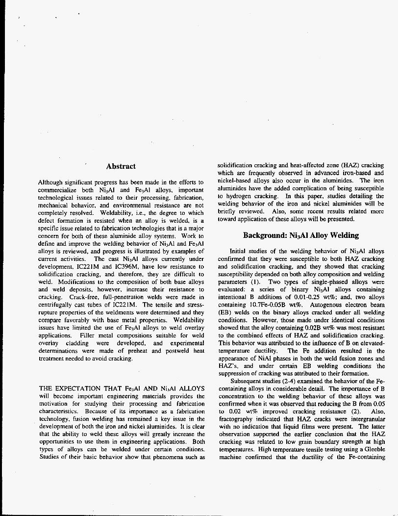
To date, the only approach used to make relatively large (> a few kg) quantities of welding wire of either IC221W or IC22 1LA is the metal-powder-core technique. In this approach, a Ni or Ni alloy strip is rolled into a tubular wire which is filled with either elemental or prealloyed metal powders. By adjusting the strip thickness and composition, and the mix of metal powders a wide range of alloy wire compositions can be produced without the need for normal ingot melting and wire drawing. A photograph of spooled IC22 1 LA wire, produced by Cor-Met using prealloyed powder supplied by Ametek, is shown in Fig. 1. Similar wire products are being produced by Stoody Company.
Fig. I . Standard spools of metal-powder-cored welding wire of IC22 1 LA.
The results presented in this paper describe the properties of welds made in centrifugally cast IC221M tubing with both IC221W and IC221LA filler metal. The welds were made by manual gas-tungsten arc (GTA) welding and radiographs indicated they were virtually free of defects. Tensile testing indicated that the weldments maintained excellent yield strength below 1OOO"C. The elongation values of the tensile
specimens were comparable to those of the base metal, except above 800°C where the weldment made with IC221LA showed relatively high ductility. Stress-rupture testing at 800- 1OOO"C showed that the weldment properties where slightly lower than those of the base metal.
Experimental
The centrifugally cast tubing used for this welding study was made from pure charge materials by induction melting under an argon cover. The cast tubes had dimensions of 95- mm OD x 6-7-mm wall thickness x 2.4-m length, and a chemical composition of: Ni-7.68A1-7.770- 1.45Mo- 1.39Zr- 0.008B-0.023C-0.005s-0.023N-0.05 10-0.37Fe-0.07Si wt%. Pieces about 150 mm long were cut from one tube, and the circumferential edges were prepared with single-vee grooves having bevels of 30". Beveled pieces were then tack welded together to maintain a root opening of 2-3 mm.
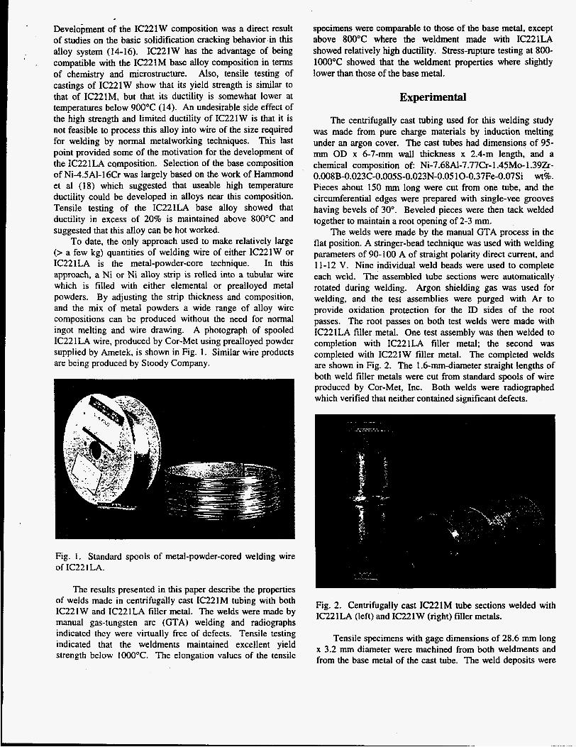
The welds were made by the manual GTA process in the flat position. A stringer-bead technique was used with welding parameters of 90-100 A of straight polarity direct current, and 11-12 V. Nine individual weld beads were used to complete each weld. The assembled tube sections were automatically rotated during welding. Argon shielding gas was used for welding, and the test assemblies were purged with Ar to provide oxidation protection for the ID sides of the root passes. The root passes on both test welds were made with IC221LA filler metal. One test assembly was then welded to completion with IC221LA filler metal; the second was completed with IC221W filler metal. The completed welds are shown in Fig. 2. The 1.6-mm-diameter straight lengths of both weld filler metals were cut from standard spools of wire produced by Cor-Met, Inc. Both welds were radiographed which verified that neither contained significant defects.
Fig. 2. Centrifugally cast IC221M tube sections welded with IC221LA (left) and IC221W (right) filler metals.
Tensile specimens with gage dimensions of 28.6 mm long x 3.2 mm diameter were machined from both weldments and from the base metal of the cast tube, The weld deposits were
centerid in the gage lengths of the weldment specimens. Tensile tests were done in air at room temperature, 600, 800, 900,1OOO, and 1 l00OC using a crosshead speed of 0 . 0 8 5 d s . Stress-rupture tests were also conducted in air at stress levels of 48-241 MPa and temperatures of 800-1O0O0C.
Examination of specimens was done using both optical metallography and scanning electron microscopy.
.
Results and Discussion
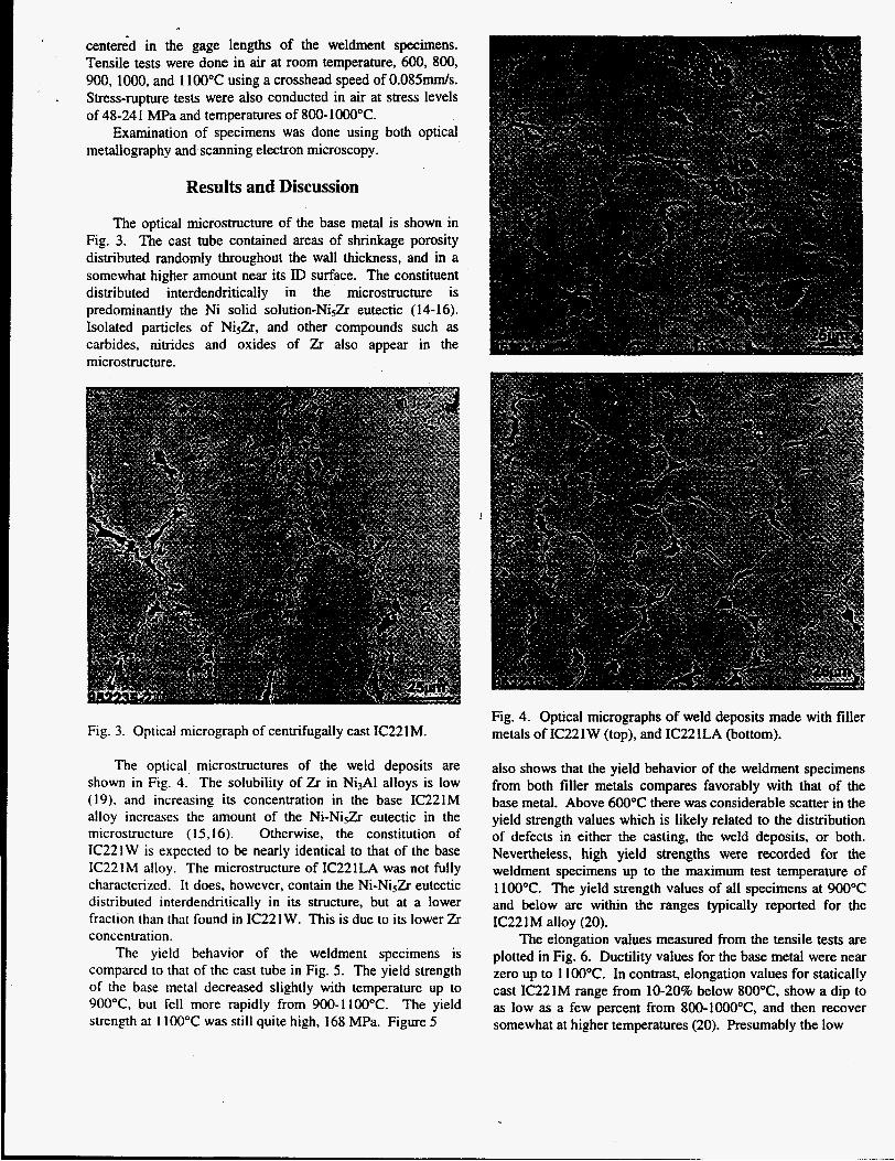
The optical microstructure of the base metal is shown in Fig. 3. The cast tube contained areas of shrinkage porosity distributed randomly throughout the wall thickness, and in a somewhat higher amount near its ID surface. The constituent distributed interdendritically in the microstructure is predominantly the Ni solid solution-Ni52 eutectic (14-16). Isolated particles of NisZr, and other compounds such as carbides, nitrides and oxides of Zr also appear in the microstructure.
Fig. 3. Optical micrograph of centrifugally cast IC221M.
The optical microstructures of the weld deposits are shown in Fig. 4. The solubility of Zr in Ni3AI alloys is low (19). and increasing its concentration in the base IC221M alloy increases the amount of the Ni-NiSZr eutectic in the microstructure (15,16). Otherwise, the constitution of IC22 1 W is expected to be nearly identical to that of the base IC221M alloy. The microstructure of IC221LA was not fully characterized. It does, however, contain the Ni-NiSZr eutectic distributed interdendritically in its structure, but at a lower fraction than that found in IC221W. This is due to its lower Zr concentration.
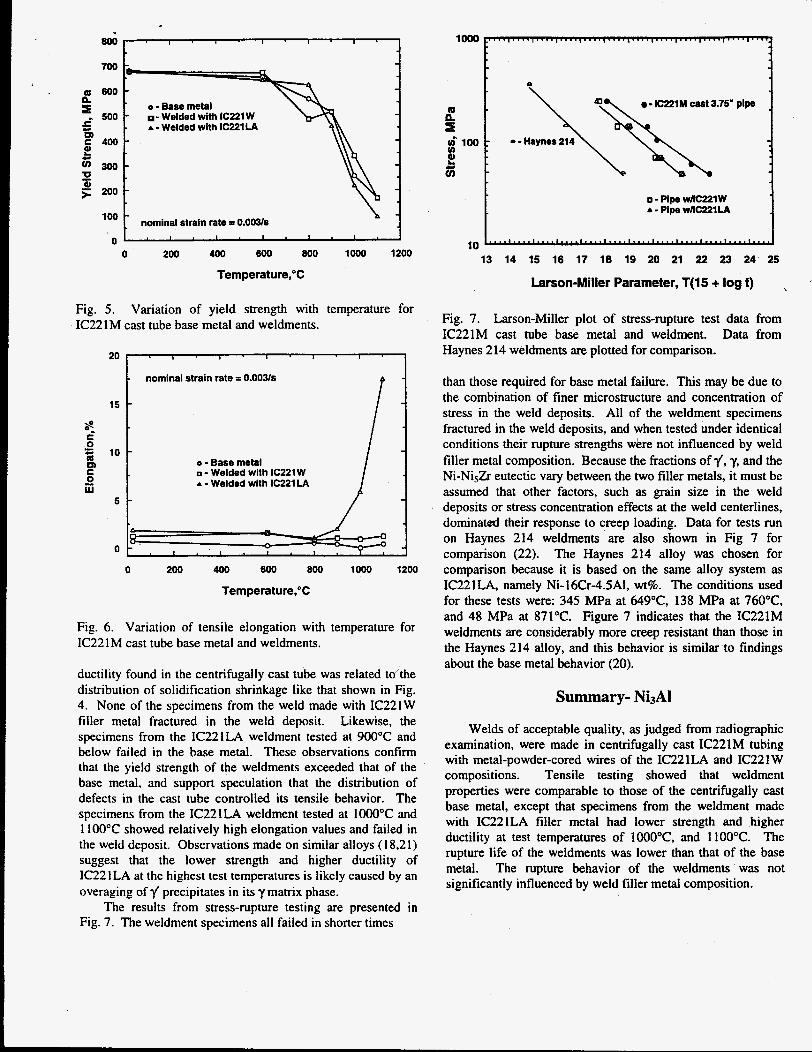
The yield behavior of the weldment specimens is compared to that of the cast tube in Fig. 5 . The yield strength of the base metal decreased slightly with temperature up to 900°C. but fell more rapidly from 900-1100°C. The yield strength at 1100°C was still quite high, 168 MPa. Figure 5
Fig. 4. Optical micrographs of weld deposits made with filler metals of IC221W (top), and IC221LA (bottom).
also shows that the yield behavior of the weldment specimens from both filler metals compares favorably with that of the base metal. Above 600°C there was considerable scatter in the yield strength values which is likely related to the distribution of defects in either the casting, the weld deposits, or both. Nevertheless, high yield strengths were recorded for the weldment specimens up to the maximum test temperature of 1 100°C. The yield strength values of all specimens at 900°C and below are within the ranges typically reported for the IC221M alloy (20).
The elongation values measured from the tensile tests are plotted in Fig. 6. Ductility values for the base metal were near zero up to 1 100°C. In contrast, elongation values for statically cast IC221M range from 10-20% below 800°C. show a dip to as low as a few percent from 800-1O0O0C, and then recover somewhat at higher temperatures (20). Presumably the low
800
700
a600
' 500 n
G F400 2
P F 200
300
al
o - Base metal - Welded with IC221 W A - Welded with IC221LA
h nominal strain rate = 0.003s
I . I . I . I . I .
0 200 400 600 800 lo00 1200
Temperature,"C
Fig. 5. IC221M
20
15
5
0
Fig. 6.
Variation of yield strength with temperature for cast tube base metal and weldments.
o - Base metal 0 - Welded with IC221 W A - Welded with IC221 LA
nominal strain rate = 0.00Ws
0 200 400 600 800 lo00 1200
Temperature,"C
Variation of tensile elongation with temperature for IC221M cast tube base metal and weldments.
ductility found in the centrifugally cast tube was related to'the distribution of solidification shrinkage like that shown in Fig. 4. None of the specimens from the weld made with IC221W filler metal fractured in the weld deposit. Likewise, the specimens from the IC221LA weldment tested at 900°C and below failed in the base metal. These observations confirm that the yield strength of the weldments exceeded that of the base metal, and support speculation that the distribution of defects in the cast tube controlled its tensile behavior. The specimens from the IC221LA weldment tested at 1OOO"C and 1100°C showed relatively high elongation values and failed in the weld deposit. Observations made on similar alloys (18,21) suggest that the lower strength and higher ductility of IC221 LA at the highest test temperatures is likely caused by an overaging of 1/ precipitates in its y matrix phase.
The results from stress-rupture testing are presented in Fig. 7. The weldment specimens all failed in shorter times
- - Haynes n\ 214
loo0 b k
- IC221M cast 3.75' pipe
Q\ ; Q 0, zi
2 ;;
$100:
o - Pipe w e 1 W A - Pipe w n c z z i u
10 r' ' " 4 " " I ' " ' " ' ' . I ' " ' I * - ' - ' 1 " ' ' l . " ' 4 r ' " 4 ' . ' "" "
13 14 15 16 17 18 19 20 21 22 23 24 25
Larson-Miller Parameter, T(15 + log f)
Fig. 7. Larson-Miller plot of stress-rupture test data from IC221M cast tube base metal and weldment. Data from Haynes 214 weldments are plotted for comparison.
than those required for base metal failure. This may be due to the combination of finer microstructure and concentration of stress in the weld deposits. All of the weldment specimens fractured in the weld deposits, and when tested under identical conditions their rupture strengths were not influenced by weld filler metal composition. Because the fractions off, 'y, and the Ni-NiSZr eutectic vary between the two filler metals, it must be assumed that other factors, such as grain size in the weld deposits or stress concentration effects at the weld centerlines, dominated their response to creep loading. Data for tests run on Haynes 214 weldments are also shown in Fig 7 for comparison (22). The Haynes 214 alloy was chosen for comparison because it is based on the same alloy system as IC221LA. namely Ni-16Cr-4.5A1, wt%. The conditions used for these tests were: 345 MPa at 649"C, 138 MPa at 760"C, and 48 MPa at 871°C. Figure 7 indicates that the IC221M weldments are considerably more creep resistant than those in the Haynes 214 alloy, and this behavior is similar to findings about the base metal behavior (20).
Summary- Ni3AI
Welds of acceptable quality, as judged from radiographic examination, were made in centrifugally cast IC221M tubing with metal-powder-cored wires of the IC221LA and IC221W compositions. Tensile testing showed that weldment properties were comparable to those of the centrifugally cast base metal, except that specimens from the weldment made with IC221LA filler metal had lower strength and higher ductility at test temperatures of 1000°C, and 1100°C. The rupture life of the weldments was lower than that of the base metal. The rupture behavior of the weldments was not significantly influenced by weld filler metal composition.
Background: Fed1 Welding
Early work on welding Fe3Al alloys (23) followed a course similar to the initial studies of Ni3Al alloys. The combination of autogenous welding and hot ductility testing was used to define the basic response of the alloys to welding. The alloys studied included a binary base alloy of Fe.72A128 and alloys containing TiB2 particles, and additions of Cr, Nb, and Mn. The TiBz was added to strengthen the base alloy and refine the grain structure of weld fusion zones. Examination of autogenous EB and GTA welds showed that these alloys were resistant to HAZ cracking but not solidification cracking. The alloys that did not contain TiBz were most resistant to cracking. The Cr Mn, and Nb additions improved cracking resistance, but Nb was most effective in this regard. The effect of TiBz was attributed to its solution during melting, and reprecipitation interdendritically where it was believed to embrittle the fusion zone microstructures.
A subsequent study found that B and Zr additions promoted solidification cracking in the Fe3Al alloys (24). The beneficial effect of Cr and Nb was confirmed and Sigmajig testing showed that alloys containing 28Al-5Cr-OSNb at% either with or without 0.2 at% C had cracking resistance in the range of austenitic stainless steels. Another important observation made in this study was that even when solidification cracking was avoided, delayed cold cracking often occurred in all of the Fe3Al alloys. The Fe3A1 alloys are susceptible to hydrogen embrittlement, and the delayed cracking of the weld was attributed to contamination of the shielding gas with traces of water vapor.
Fasching et al (25) proposed that refinement of grain size would improve the intrinsic ductility of weld fusion zones, and thereby reduce their susceptibility to hydrogen cracking. Both a variation in welding heat input and magnetic arc oscillation were used to modify the grain structure of autogenous GTA welds in an F%Al alloy (FA129) with a nominal composition of Fe-28Al-5Cr-OSNb 0.2C at%. Weld fusion zone microstructures were produced with grain sizes of 115, 172, 300, and 530 pm, and aspect ratios of 1.3, 2.4, 4.5 and 7.4, respectively. Tensile testing in atmospheres where the level of water vapor was controlled showed that the finest fusion zone grain structure resulted in the highest weldment fracture strength and the most resistance to hydrogen embrittlement.
Recent Developments: Fe3Al Alloy Welding
Current efforts on welding Fe3A1 alloys (26) are directed toward minimizing hydrogen cracking and developing the filler metals, processes and procedures required for commercial applications. Recent testing shows that hydrogen cracking roughly correlates with A1 concentration in weld deposits, with high (> 26 wt%) and low AI (e 12 wt%) levels being most susceptible to cracking.
Heat treatments also appear effective for controlling hydrogen cracking of the Fe3A1 alloys. Evaluation of heat treatments was done by producing a series of standardized welds with preheat and postweld heat treatments reduced in
50°C steps starting at 350°C and 750°C respectively. It was found that preheat temperatures as low as 250°C would sometimes yield crack-free weld deposits, but that 350°C was required to completely avoid cracking. Similarly, reduced postweld heat treatment temperatures would often produce sound deposits which would subsequently crack during liquid penetrant examination. It appears that 350°C and 750°C are minimum temperatures required to control hydrogen cracking.
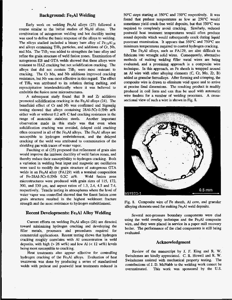
The Fe3Al alloys, such as FA129, are also difficult to fabricate into wrought solid wires. Consequently, alternative methods of making welding filler metal wires are being evaluated, and a promising approach is a composite wire technique. In this approach, an Fe sheath is wrapped around an AI wire with other alloying elements (C, Cr, Mo, Zr, B) added as granular ferroalloys. After forming and crimping, the composite wire is drawn to eliminate void space and to arrive at precise final dimensions. The resulting product is readily produced in coil form and can thus be used with automatic wire feeders for a number of welding processes. A cross- sectional view of such a wire is shown in Fig. 8.
Q.5 mm
Fig. 8. Composite wire of Fe sheath, A1 core, and granular alloying elements used for making F%Al weld deposits.
Several non-pressure boundary components were clad using the weld overlay technique and the Fe3A1 composite wire, and they were placed in service in a paper mill recovery boiler. The performance of the clad components is still being evaluated.
Acknowledgment
Review of the manuscript by J. F. King and R. W. Swindeman are kindly appreciated. C. R. Howell and R. W. Swindeman assisted with mechanical property testing. The contributions of J. D. McNabb to the welding work cannot be overestimated. This work was sponsored by the U.S.

c "
Department of Energy, Assistant Secretary for Energy 20 Deevi, S. C. and V. K. Sikka, Intermetallics, 4, 357-375 Efficiency and Renewable Energy, Ofice of Industrial (1996) Technologies, Advanced Industrial Materials Program under 21 Herchenroeder, R. B., G. Y. Lai and K. V. Rao, J. Metals,
Research Corporation. 22 McCoy, H. E., ORNL,/TM-9891, p. 52-61, Oak Ridge contract DE-AC05-840R21400 with Lockheed Martin Energy 35, 16-22 (1983).
1
2.
6
7
8
9
Refer en c e s
David, S. A., W. A. Jemian, C. T. Liu and J. A. Horton, Weld. J., 64( l), 22s-28s (1985). Santella, M. L., S. A. David and C. L. White, in MRS Symposia Proceedings Vol. 39, High-Temperature Ordered Intermetallic Alloys, p. 495-503, Materials Research Society, 1985. Santella, M. L. and S. A. David, Weld. J., 65(5), 129s- 137s (1986). Santella, M. L., M. C. Maguire and S. A. David, Weld. J.,
Santella, M. L., S. A. David and J. A. Horton, in Proceeding of International Conference on Trends in Welding Research, Advances in Welding Science and Technology, p. 629-633, ASM International, 1987. Santella, M. L., J. A. Horton and S. A. David, Weld. J.,
Li, H. and T. K. Chaki, in MRS Symposia Proceedings Vol. 213, High-Temperature Ordered Intermetallic Alloys IV, p. 919-924, Materials Research Society, 1991. Li, H. and T. K. Chaki, Materials Science and Engineering, A183, 131-138 (1994). Edwards, G. R., M. C. Maguire and B. K. Damkroger, in Proceeding of 2"d International Conference on Trends in Welding Research, Recent Trends in Welding Science and Technology, p. 649-654, ASM International, 1990.
68( l), 19s-27s (1989).
67(3), 63s-69s (1988).
National Laboratory, 1986. 23 David, S. A., J. A. Horton, C. G. McKamey, T. Zacharia
and R. W. Reed, Weld. J., 68(9), 372s-381s (1989). 24 David, S. A. and T. Zacharia, Weld. J., 72(5), 201s-207s
(1993). 25 Fasching, A. A., G. R. Edwards and S. A. David, in
Proceeding of 3"' International Conference on Trends in Welding Research, Trends in Welding Research, p. 147- 152, ASM International, 1995.
26 Goodwin, G. M., in proceedings of the 10" Annual Conference on Fossil Energy Materials, p. 97-108, Oak Ridge National Laboratory, 1996.
10 Maguire, M. C., G. R. Edwards and S. A. David, Weld. J.,
11 Liu, C. T. and V. K. Sikka, J. Metals, 38(5), 19-21 (1986). 12 Li, H. and T. K. Chaki, in MRS Symposia Proceedings
Vol. 288, High-Temperature Ordered Intermetallic Alloys V, p. 1167-1172, Materials Research Society, 1993.
13 Li, H. and T. K. Chaki, in Processing and Fabrication of Advanced Materials for High Temperature Applications II, p. 563-591, The Minerals, Metals & Materials Society, 1993.
14 Santella, M. L., Scripta Met., 28, 1305-1310 (1993). 15 Santella, M. L. and V. K. Sikka, in AWS Conference
Proceedings, Advance Joining Technologies for New Materials 11, p. 59-75, American Welding Society, 1994.
16 Santella, M. L. and Z. Feng, in Proceeding of 3d International Conference on Trends in Welding Research, Trends in Welding Research, p. 609-614, ASM International, 1995.
17 Borland, J. C., British Weld. J., 7,508-512 (1960). 18 Hammond, C. M., R. A. Flinn and L. Thomassen, Trans.
19 Shouichi, O., Y. Oya and T. SUZUki, Acta metall., 32(2), 289-298 (1984).
71(7), 231s-242s (1992).
The submitted manuscript was authored by a contractor of the U.S. under cmtract NO, DE-AC05-84OR21400. Accordingly, the
U.S. Government retains a nonexclusive, royalty-free license to publish or reproduce the published form of this contribution, or allow others to do so, for US. Government purposes.
A m , 221,400-405 (1961).