Embed Size (px)
DESCRIPTION
Stratix 8000 Hardware User Manual
Citation preview

Hardware User Manual
Catalog Numbers 1783-MS06T, 1783-MS10T,1783-MX08T, 1783-MX08F
Stratix 8000 Ethernet Managed Switches
Important User InformationSolid state equipment has operational characteristics differing from those of electromechanical equipment. Safety Guidelines for the Application, Installation and Maintenance of Solid State Controls (publication SGI-1.1 available from your local Rockwell Automation sales office or online at http://literature.rockwellautomation.com) describes some important differences between solid state equipment and hard-wired electromechanical devices. Because of this difference, and also because of the wide variety of uses for solid state equipment, all persons responsible for applying this equipment must satisfy themselves that each intended application of this equipment is acceptable.
In no event will Rockwell Automation, Inc. be responsible or liable for indirect or consequential damages resulting from the use or application of this equipment.
The examples and diagrams in this manual are included solely for illustrative purposes. Because of the many variables and requirements associated with any particular installation, Rockwell Automation, Inc. cannot assume responsibility or liability for actual use based on the examples and diagrams.
No patent liability is assumed by Rockwell Automation, Inc. with respect to use of information, circuits, equipment, or software described in this manual.
Reproduction of the contents of this manual, in whole or in part, without written permission of Rockwell Automation, Inc., is prohibited.
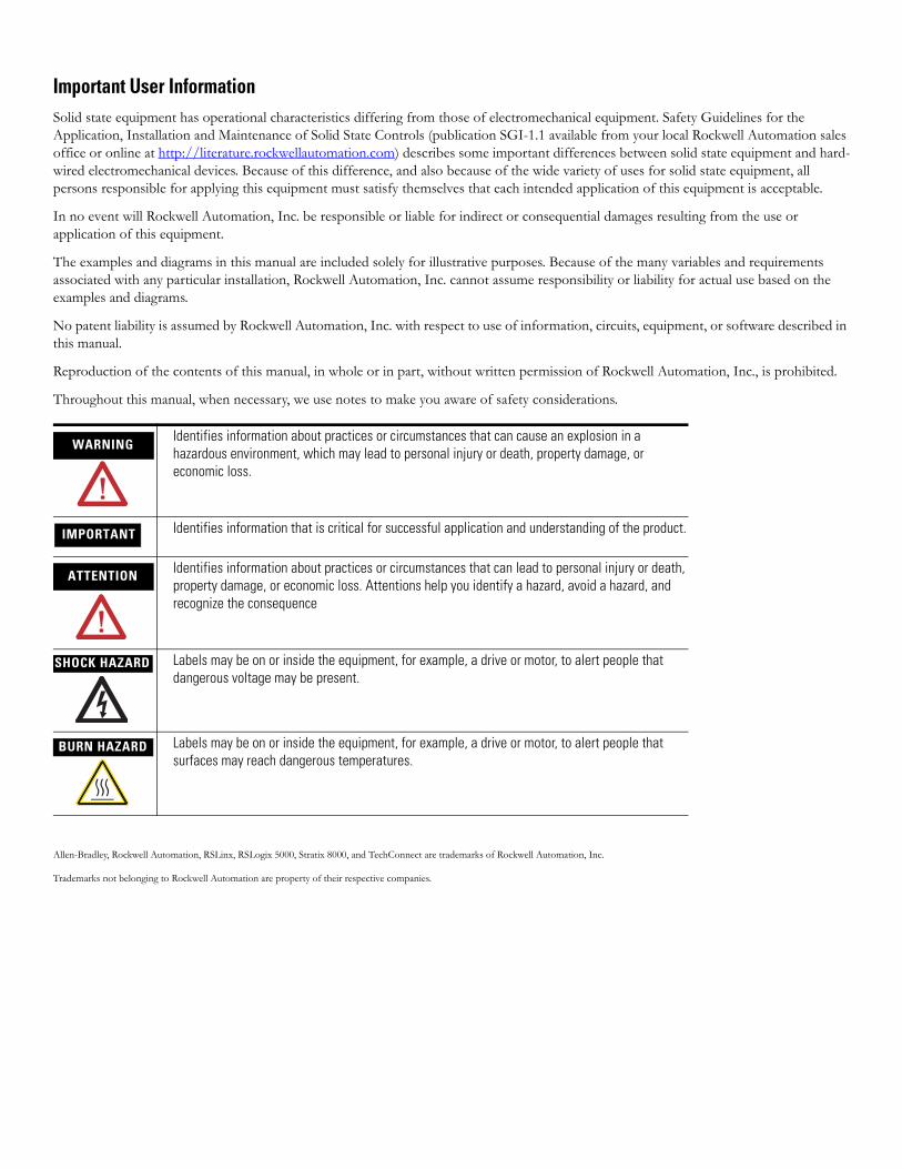
Throughout this manual, when necessary, we use notes to make you aware of safety considerations.
Allen-Bradley, Rockwell Automation, RSLinx, RSLogix 5000, Stratix 8000, and TechConnect are trademarks of Rockwell Automation, Inc.
Trademarks not belonging to Rockwell Automation are property of their respective companies.
WARNINGIdentifies information about practices or circumstances that can cause an explosion in a hazardous environment, which may lead to personal injury or death, property damage, or economic loss.
IMPORTANT Identifies information that is critical for successful application and understanding of the product.
ATTENTION Identifies information about practices or circumstances that can lead to personal injury or death, property damage, or economic loss. Attentions help you identify a hazard, avoid a hazard, and recognize the consequence
SHOCK HAZARD Labels may be on or inside the equipment, for example, a drive or motor, to alert people that dangerous voltage may be present.
BURN HAZARD Labels may be on or inside the equipment, for example, a drive or motor, to alert people that surfaces may reach dangerous temperatures.

Preface
About This Publication This publication describes the physical and performance characteristics of the Stratix 8000 Ethernet Managed Switches. In addition, this publication provides the following:
• Detailed installation information• How to use the switch• Troubleshooting information
This guide does not describe system messages that you might receive or how to configure your switch. For this information, see the Additional Resources section on page 6.
Who Should Use This Publication
This guide is for the person installing Stratix 8000 Ethernet Managed Switches. We assume that you are familiar with the concepts and terminology of the Ethernet protocol and local area networking.
5Publication 1783-UM002C-EN-P - April 2009 5
Preface
Additional Resources These documents contain additional information concerning this Rockwell Automation product.
You can view or download publications at http://literature.rockwellautomation.com. To order paper copies of technical documentation, contact your local Rockwell Automation distributor or sales representative.
Resource Description
Stratix 8000 Ethernet Managed Switches Installation Instructions, publication 1783-IN005
Describes how to get started installing and configuring the switch.
Stratix 8000 Ethernet Managed Switches Software User Manual, publication 1783-UM003
Provides detailed information on configuring and managing your switches.
Stratix 8000 Ethernet Managed Switches Release Notes, publication 1783-RN002
Lists enhancements and anomalies associated with the software release.
Device Manager online help (provided with the switch)
Provides context-sensitive information on configuring and using the switch, including system messages.
Industrial Automation Wiring and Grounding Guidelines, publication 1770-4.1
Provides general guidelines for installing a Rockwell Automation industrial system.
Product Certifications website, http://ab.com
Provides declarations of conformity, certificates, and other certification details.
6 Publication 1783-UM002C-EN-P - April 2009
Table of Contents
PrefaceAbout This Publication . . . . . . . . . . . . . . . . . . . . . . . . . . . . . . . . . . . . . . 5Who Should Use This Publication . . . . . . . . . . . . . . . . . . . . . . . . . . . . . 5Additional Resources . . . . . . . . . . . . . . . . . . . . . . . . . . . . . . . . . . . . . . . . 6
Chapter 1Start About the Switches . . . . . . . . . . . . . . . . . . . . . . . . . . . . . . . . . . . . . . . . . 8
Power and Relay Connector . . . . . . . . . . . . . . . . . . . . . . . . . . . . . . . . . 11Console Port. . . . . . . . . . . . . . . . . . . . . . . . . . . . . . . . . . . . . . . . . . . . . . 12Dual-Purpose Uplink Ports . . . . . . . . . . . . . . . . . . . . . . . . . . . . . . . . . . 1210/100 Ports. . . . . . . . . . . . . . . . . . . . . . . . . . . . . . . . . . . . . . . . . . . . . . 13100BASE-FX Ports . . . . . . . . . . . . . . . . . . . . . . . . . . . . . . . . . . . . . . . . 13Rear Panel . . . . . . . . . . . . . . . . . . . . . . . . . . . . . . . . . . . . . . . . . . . . . . . . 13Cabling . . . . . . . . . . . . . . . . . . . . . . . . . . . . . . . . . . . . . . . . . . . . . . . . . . 14
Auto-MDIX Feature . . . . . . . . . . . . . . . . . . . . . . . . . . . . . . . . . . . . 14Status Indicators . . . . . . . . . . . . . . . . . . . . . . . . . . . . . . . . . . . . . . . . . . . 15
Switch and Port Status Indicators . . . . . . . . . . . . . . . . . . . . . . . . . . 15Dual-purpose Port Status Indicators . . . . . . . . . . . . . . . . . . . . . . . 17Expansion Module Status Indicators . . . . . . . . . . . . . . . . . . . . . . . 18
CompactFlash Memory Card. . . . . . . . . . . . . . . . . . . . . . . . . . . . . . . . . 19
Chapter 2Install the Switch Installation Guidelines . . . . . . . . . . . . . . . . . . . . . . . . . . . . . . . . . . . . . . 24
Environment and Enclosure Guidelines . . . . . . . . . . . . . . . . . . . . 24Before You Begin. . . . . . . . . . . . . . . . . . . . . . . . . . . . . . . . . . . . . . . . . . 24
Place the Switch . . . . . . . . . . . . . . . . . . . . . . . . . . . . . . . . . . . . . . . . 25Verify Package Contents . . . . . . . . . . . . . . . . . . . . . . . . . . . . . . . . . . . . 26Add Modules to the Switch . . . . . . . . . . . . . . . . . . . . . . . . . . . . . . . . . . 26
Expansion Module Configurations . . . . . . . . . . . . . . . . . . . . . . . . . 26Install the Switch . . . . . . . . . . . . . . . . . . . . . . . . . . . . . . . . . . . . . . . . . . 29
Attach Expansion Modules (optional) . . . . . . . . . . . . . . . . . . . . . . 29Mount the Switch. . . . . . . . . . . . . . . . . . . . . . . . . . . . . . . . . . . . . . . 32Install the SFP Module (optional) . . . . . . . . . . . . . . . . . . . . . . . . . . 37Ground the Switch. . . . . . . . . . . . . . . . . . . . . . . . . . . . . . . . . . . . . . 38Wire the DC Power Source . . . . . . . . . . . . . . . . . . . . . . . . . . . . . . . 40Attach the Power and Relay Connector . . . . . . . . . . . . . . . . . . . . . 42Wire the External Alarms (Optional) . . . . . . . . . . . . . . . . . . . . . . . 44
Install or Remove the CompactFlash Card. . . . . . . . . . . . . . . . . . . . . . 47Set Up the Switch Initially with Express Setup. . . . . . . . . . . . . . . . . . . 48Configure and Manage the Switch. . . . . . . . . . . . . . . . . . . . . . . . . . . . . 53
Use the Device Manager Web Interface . . . . . . . . . . . . . . . . . . . . . 53Use RSLogix 5000 Software . . . . . . . . . . . . . . . . . . . . . . . . . . . . . . 54Download Cisco Network Assistant. . . . . . . . . . . . . . . . . . . . . . . . 56Use the Command-Line Interface. . . . . . . . . . . . . . . . . . . . . . . . . . 57Use SNMP Management Applications . . . . . . . . . . . . . . . . . . . . . . 57
3Publication 1783-UM002C-EN-P - April 2009 3

Reset the Switch to Factory Defaults . . . . . . . . . . . . . . . . . . . . . . . . . . 58Connect to the Switch Ports . . . . . . . . . . . . . . . . . . . . . . . . . . . . . . . . . 58
Connect to 10/100 Copper Ports . . . . . . . . . . . . . . . . . . . . . . . . . . 59Connect to Dual-purpose Uplink (10/100/1000 and SFP Fiber) Ports . . . . . . . . . . . . . . . . . . . . . . . . . . . . . . . . . . . . . . . . . . . . . . . . . 59Connect to 100BaseFX Ports . . . . . . . . . . . . . . . . . . . . . . . . . . . . . 61
Verify Port Connectivity . . . . . . . . . . . . . . . . . . . . . . . . . . . . . . . . . . . . 61Verify Switch Operation . . . . . . . . . . . . . . . . . . . . . . . . . . . . . . . . . . . . 62Connect a Computer or a Terminal to the Console Port. . . . . . . . . . . 62Run a Power-on Self-test (POST) . . . . . . . . . . . . . . . . . . . . . . . . . . . . . 63Verify POST Results . . . . . . . . . . . . . . . . . . . . . . . . . . . . . . . . . . . . . . . 63Disconnect Power . . . . . . . . . . . . . . . . . . . . . . . . . . . . . . . . . . . . . . . . . 64Install and Remove SFP Modules . . . . . . . . . . . . . . . . . . . . . . . . . . . . . 64
Install SFP Modules into SFP Module Slots . . . . . . . . . . . . . . . . . 64Remove SFP Modules from SFP Module Slots . . . . . . . . . . . . . . . 65
Connect to SFP Modules . . . . . . . . . . . . . . . . . . . . . . . . . . . . . . . . . . . . 67
Chapter 3Troubleshoot the Switch Obtain Troubleshooting Information . . . . . . . . . . . . . . . . . . . . . . . . . . 69
Verify Switch POST Results . . . . . . . . . . . . . . . . . . . . . . . . . . . . . . . . . 69View POST Results With a Terminal . . . . . . . . . . . . . . . . . . . . . . . 70
Verify Switch Status Indicators . . . . . . . . . . . . . . . . . . . . . . . . . . . . . . . 70Verify Switch Connections . . . . . . . . . . . . . . . . . . . . . . . . . . . . . . . . . . 70
Bad or Damaged Cable . . . . . . . . . . . . . . . . . . . . . . . . . . . . . . . . . . 70Ethernet and Fiber Cables. . . . . . . . . . . . . . . . . . . . . . . . . . . . . . . . 71Link Status . . . . . . . . . . . . . . . . . . . . . . . . . . . . . . . . . . . . . . . . . . . . 72Transceiver Issues . . . . . . . . . . . . . . . . . . . . . . . . . . . . . . . . . . . . . . 72Port and Interface Settings . . . . . . . . . . . . . . . . . . . . . . . . . . . . . . . 73
Verify Switch Performance . . . . . . . . . . . . . . . . . . . . . . . . . . . . . . . . . . 73Speed, Duplex, and Autonegotiation . . . . . . . . . . . . . . . . . . . . . . . 73Autonegotiation and Network Interface Cards (NICs) . . . . . . . . . 74Cabling Distance . . . . . . . . . . . . . . . . . . . . . . . . . . . . . . . . . . . . . . . 74
Obtain Configurtion Information . . . . . . . . . . . . . . . . . . . . . . . . . . . . . 74
Chapter 4Cable and Connectors 10/100 and 10/100/1000 Ports . . . . . . . . . . . . . . . . . . . . . . . . . . . . . . 75
Connect to 10BASE-T- and 100BASE-TX-Compatible Devices. 76100BASE-FX Ports . . . . . . . . . . . . . . . . . . . . . . . . . . . . . . . . . . . . . . . . 78SFP Module Ports . . . . . . . . . . . . . . . . . . . . . . . . . . . . . . . . . . . . . . . . . 78Dual-purpose Ports . . . . . . . . . . . . . . . . . . . . . . . . . . . . . . . . . . . . . . . . 79Console Port. . . . . . . . . . . . . . . . . . . . . . . . . . . . . . . . . . . . . . . . . . . . . . 79Cable and Adapter Specifications . . . . . . . . . . . . . . . . . . . . . . . . . . . . . 80
SFP Module Cable Specifications . . . . . . . . . . . . . . . . . . . . . . . . . . 80Adapter Pinouts . . . . . . . . . . . . . . . . . . . . . . . . . . . . . . . . . . . . . . . . . . . 80
Index
4 Publication 1783-UM002C-EN-P - April 2009

Chapter 1
Start
This chapter provides a functional overview of the switches and covers these topics.
Topic Page
About the Switches 8
Power and Relay Connector 11
Console Port 12
Dual-Purpose Uplink Ports 12
10/100 Ports 13
100BASE-FX Ports 13
Rear Panel 13
Cabling 14
Status Indicators 15
CompactFlash Memory Card 19
7Publication 1783-UM002C-EN-P - April 2009 7
Chapter 1
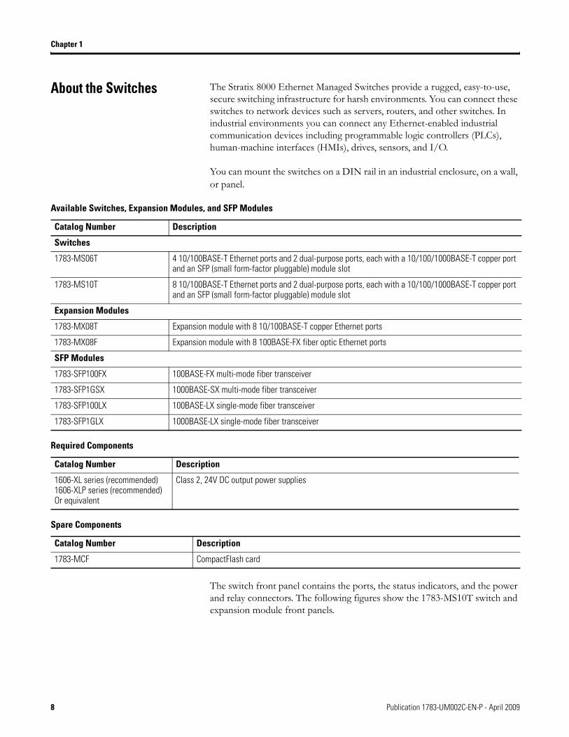
About the Switches The Stratix 8000 Ethernet Managed Switches provide a rugged, easy-to-use, secure switching infrastructure for harsh environments. You can connect these switches to network devices such as servers, routers, and other switches. In industrial environments you can connect any Ethernet-enabled industrial communication devices including programmable logic controllers (PLCs), human-machine interfaces (HMIs), drives, sensors, and I/O.
You can mount the switches on a DIN rail in an industrial enclosure, on a wall, or panel.
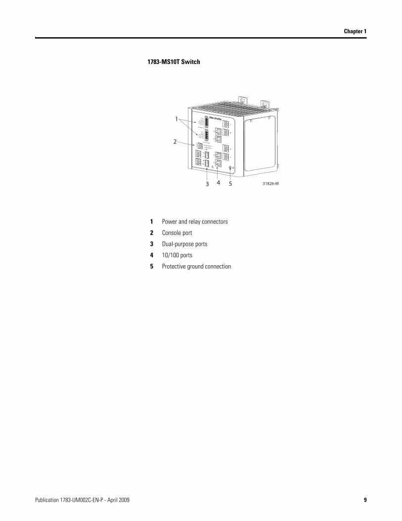
The switch front panel contains the ports, the status indicators, and the power and relay connectors. The following figures show the 1783-MS10T switch and expansion module front panels.
Available Switches, Expansion Modules, and SFP Modules
Catalog Number Description
Switches
1783-MS06T 4 10/100BASE-T Ethernet ports and 2 dual-purpose ports, each with a 10/100/1000BASE-T copper port and an SFP (small form-factor pluggable) module slot
1783-MS10T 8 10/100BASE-T Ethernet ports and 2 dual-purpose ports, each with a 10/100/1000BASE-T copper port and an SFP (small form-factor pluggable) module slot
Expansion Modules
1783-MX08T Expansion module with 8 10/100BASE-T copper Ethernet ports
1783-MX08F Expansion module with 8 100BASE-FX fiber optic Ethernet ports
SFP Modules
1783-SFP100FX 100BASE-FX multi-mode fiber transceiver
1783-SFP1GSX 1000BASE-SX multi-mode fiber transceiver
1783-SFP100LX 100BASE-LX single-mode fiber transceiver
1783-SFP1GLX 1000BASE-LX single-mode fiber transceiver
Required Components
Catalog Number Description
1606-XL series (recommended)1606-XLP series (recommended)Or equivalent
Class 2, 24V DC output power supplies
Spare Components
Catalog Number Description
1783-MCF CompactFlash card
8 Publication 1783-UM002C-EN-P - April 2009
Chapter 1
1783-MS10T Switch
1 Power and relay connectors
2 Console port
3 Dual-purpose ports
4 10/100 ports
5 Protective ground connection
Publication 1783-UM002C-EN-P - April 2009 9
Chapter 1
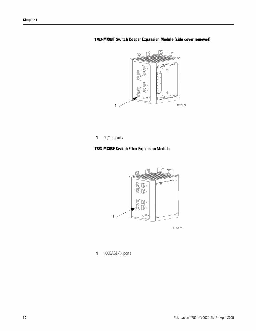
1783-MX08T Switch Copper Expansion Module (side cover removed)
1783-MX08F Switch Fiber Expansion Module
31827-M1
1 10/100 ports
31828-M
1
1 100BASE-FX ports
10 Publication 1783-UM002C-EN-P - April 2009
Chapter 1
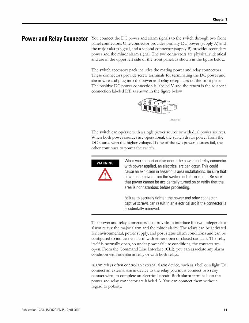
Power and Relay Connector You connect the DC power and alarm signals to the switch through two front panel connectors. One connector provides primary DC power (supply A) and the major alarm signal, and a second connector (supply B) provides secondary power and the minor alarm signal. The two connectors are physically identical and are in the upper left side of the front panel, as shown in the figure below.
The switch accessory pack includes the mating power and relay connectors. These connectors provide screw terminals for terminating the DC power and alarm wire and plug into the power and relay receptacles on the front panel. The positive DC power connection is labeled V, and the return is the adjacent connection labeled RT, as shown in the figure below.
The switch can operate with a single power source or with dual power sources. When both power sources are operational, the switch draws power from the DC source with the higher voltage. If one of the two power sources fail, the other continues to power the switch.
The power and relay connectors also provide an interface for two independent alarm relays: the major alarm and the minor alarm. The relays can be activated for environmental, power supply, and port status alarm conditions and can be configured to indicate an alarm with either open or closed contacts. The relay itself is normally open, so under power failure conditions, the contacts are open. From the Command Line Interface (CLI), you can associate any alarm condition with one alarm relay or with both relays.
Alarm relays often control an external alarm device, such as a bell or a light. To connect an external alarm device to the relay, you must connect two relay contact wires to complete an electrical circuit. Both alarm terminals on the power and relay connector are labeled A. You can connect them without regard to polarity.
WARNING When you connect or disconnect the power and relay connector with power applied, an electrical arc can occur. This could cause an explosion in hazardous area installations. Be sure that power is removed from the switch and alarm circuit. Be sure that power cannot be accidentally turned on or verify that the area is nonhazardous before proceeding.
Failure to securely tighten the power and relay connector captive screws can result in an electrical arc if the connector is accidentally removed.
RT AVA
31783-M
Publication 1783-UM002C-EN-P - April 2009 11
Chapter 1
See the Stratix 8000 Ethernet Managed Switches Software User Manual, publication 1783-UM003A, for more information on alarm configuration..
For more information about the power and relay connector, see Chapter 4, Cable and Connectors.
Console Port For configuring, monitoring, and managing the switch, you can connect a switch to a computer through the console port and the supplied RJ45-to-DB-9 adapter cable. If you want to connect a switch to a terminal, you need to provide an RJ45-to-DB-25 female DTE adapter. For console-port and adapter-pinout information, see the Two Twisted-pair Straight-through Cable Schematic on page 76.
Dual-Purpose Uplink Ports The two dual-purpose uplink ports may each be configured for RJ45 (copper) or SFP (fiber) media types. Only one of these connections in each of the dual-purpose ports can be active at a time. If both ports are connected, the SFP module port has priority.
You can set the copper RJ45 ports to operate at 10, 100, or 1000 Mb/s in full-duplex or half-duplex mode. You can configure them as fixed 10, 100, or 1000 Mb/s (Gigabit) Ethernet ports and can configure the duplex setting.
You can use approved Gigabit (or 100 Mbps) Ethernet SFP modules to establish fiber-optic connections to other switches. These transceiver modules are field-replaceable, providing the uplink interfaces when inserted in an SFP module slot. You use fiber-optic cables with LC connectors to connect to a fiber-optic SFP module. These ports operate in the full duplex mode only.
WARNING If you connect or disconnect the console cable with power applied to the switch or any device on the network, an electrical arc can occur. This could cause an explosion in hazardous location installations. Be sure that power is removed or the area is nonhazardous before proceeding.
To verify switch operation, perform POST on the switch in a nonhazardous location before installation.
12 Publication 1783-UM002C-EN-P - April 2009
Chapter 1
10/100 Ports You can set the 10/100 ports to operate at 10 or 100 Mb/s in full-duplex or half-duplex mode. You can also set these ports for speed and duplex autonegotiation in compliance with IEEE 802.3-2002. (The default setting is autonegotiate.)
When set for autonegotiation, the port senses the speed and duplex settings of the attached device. If the connected device also supports autonegotiation, the switch port negotiates the best connection (that is, the fastest line speed that both devices support and full-duplex transmission if the attached device supports it) and configures itself accordingly. In all cases, the attached device must be within 100 m (328 ft.) of the switch.
100BASE-FX Ports The IEEE 802.3-2002 100BASE-FX ports (on the 1783-MX08F expansion module) provide full-duplex 100 Mb/s connectivity over multimode fiber (MMF) cables. These ports use a built-in, small-form-factor fixed (SFF) fiber-optic transceiver module that accepts a dual LC connector. The cable can be up to 2 km (1.24 miles) in length.
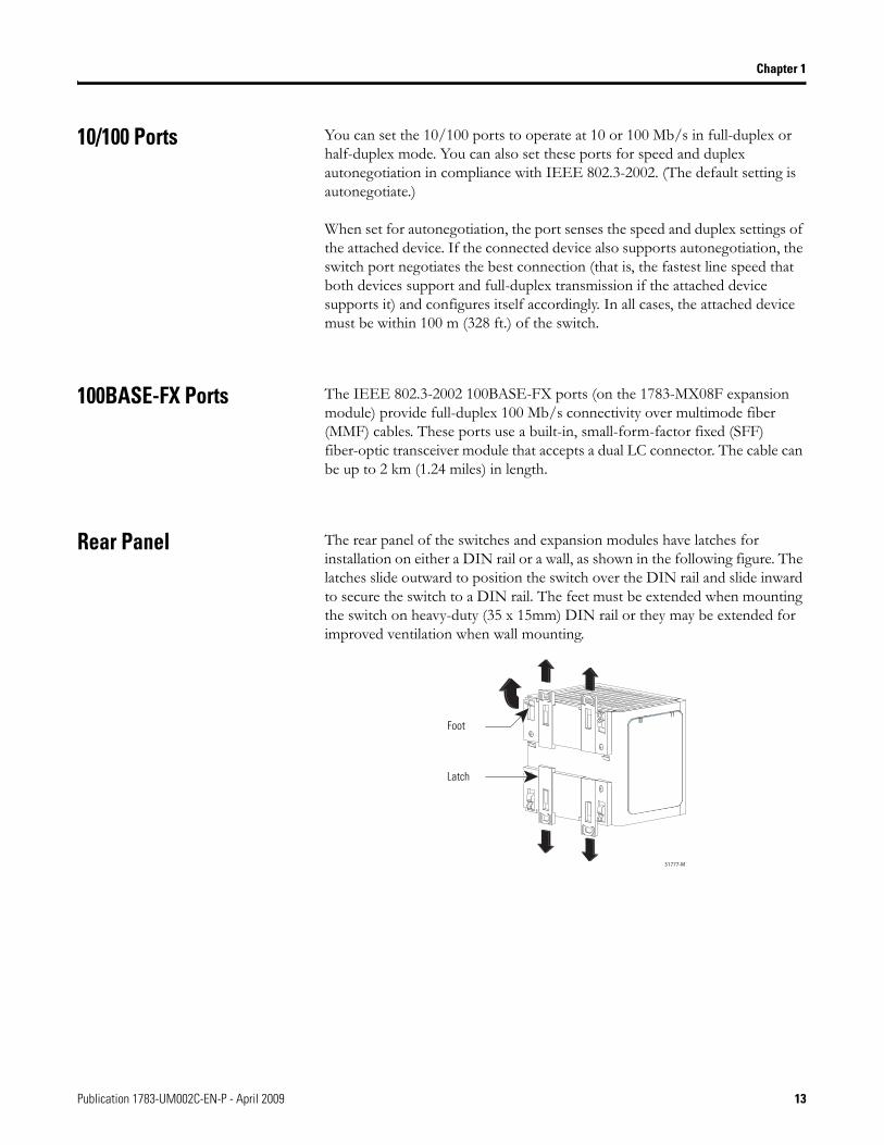
Rear Panel The rear panel of the switches and expansion modules have latches for installation on either a DIN rail or a wall, as shown in the following figure. The latches slide outward to position the switch over the DIN rail and slide inward to secure the switch to a DIN rail. The feet must be extended when mounting the switch on heavy-duty (35 x 15mm) DIN rail or they may be extended for improved ventilation when wall mounting.
31777-M
Latch
Foot
Publication 1783-UM002C-EN-P - April 2009 13
Chapter 1
Cabling 100BASE-TX traffic requires Category 5 cable. 10BASE-T traffic can use Category 3 or Category 4 cables.
When connecting the switch to workstations, servers, and routers, straight-through cables are normally used. However, the automatic medium-dependent interface crossover (auto-MDIX) feature of the switch is enabled by default and will automatically re-configure the ports to use either straight-through or crossover cable type.
Auto-MDIX Feature
The Auto-MDIX feature is enabled by default. When the auto-MDIX feature is enabled, the switch detects the required cable type (straight-through or crossover) for copper Ethernet connections and configures the interfaces accordingly.
You can use the command-line interface (CLI) to disable the auto-MDIX feature. See the online help for more information.
14 Publication 1783-UM002C-EN-P - April 2009
Chapter 1
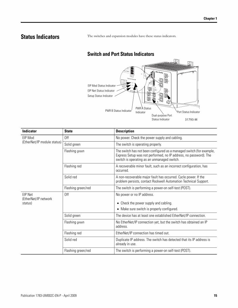
Status Indicators The switches and expansion modules have these status indicators.
Switch and Port Status Indicators
VRT
AA
31793-M
EIP Mod Status Indicator
EIP Net Status Indicator
Setup Status Indicator
PWR A Status IndicatorPWR B Status Indicator
Dual-purpose Port Status Indicator
Port Status Indicator
Indicator State Description
EIP Mod(EtherNet/IP module status)
Off No power. Check the power supply and cabling.
Solid green The switch is operating properly.
Flashing green The switch has not been configured as a managed switch (for example, Express Setup was not performed, no IP address, no password). The switch is operating as an unmanaged switch.
Flashing red A recoverable minor fault, such as an incorrect configuration, has occurred.
Solid red A non-recoverable major fault has occurred. Cycle power. If the problem persists, contact Rockwell Automation Technical Support.
Flashing green/red The switch is performing a power-on self-test (POST).
EIP Net(EtherNet/IP network status)
Off No power or no IP address.
• Check the power supply and cabling.
• Make sure switch is properly configured.
Solid green The device has at least one established EtherNet/IP connection.
Flashing green No EtherNet/IP connection yet, but the switch has obtained an IP address.
Flashing red EtherNet/IP connection has timed out.
Solid red Duplicate IP address. The switch has detected that its IP address is already in use.
Flashing green/red The switch is performing a power-on self-test (POST).
Publication 1783-UM002C-EN-P - April 2009 15
Chapter 1
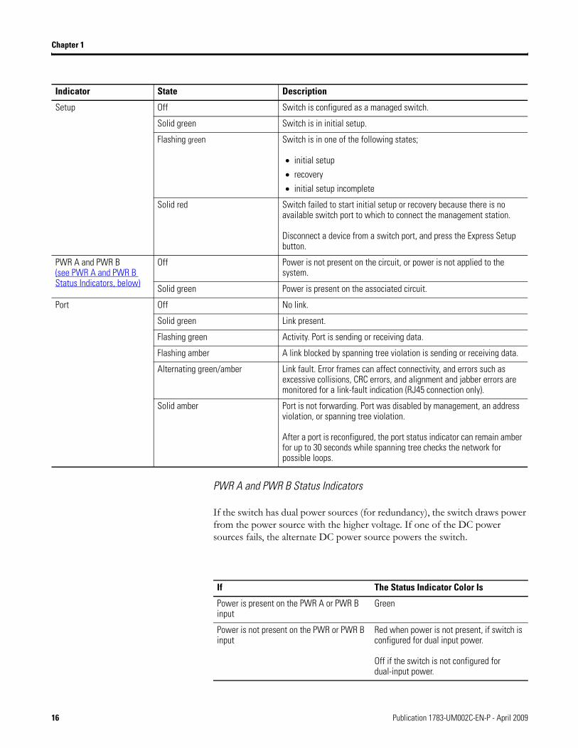
PWR A and PWR B Status Indicators
If the switch has dual power sources (for redundancy), the switch draws power from the power source with the higher voltage. If one of the DC power sources fails, the alternate DC power source powers the switch.
Setup Off Switch is configured as a managed switch.
Solid green Switch is in initial setup.
Flashing green Switch is in one of the following states;
• initial setup
• recovery
• initial setup incomplete
Solid red Switch failed to start initial setup or recovery because there is no available switch port to which to connect the management station.
Disconnect a device from a switch port, and press the Express Setup button.
PWR A and PWR B(see PWR A and PWR B Status Indicators, below)
Off Power is not present on the circuit, or power is not applied to the system.
Solid green Power is present on the associated circuit.
Port Off No link.
Solid green Link present.
Flashing green Activity. Port is sending or receiving data.
Flashing amber A link blocked by spanning tree violation is sending or receiving data.
Alternating green/amber Link fault. Error frames can affect connectivity, and errors such as excessive collisions, CRC errors, and alignment and jabber errors are monitored for a link-fault indication (RJ45 connection only).
Solid amber Port is not forwarding. Port was disabled by management, an address violation, or spanning tree violation.
After a port is reconfigured, the port status indicator can remain amber for up to 30 seconds while spanning tree checks the network for possible loops.
Indicator State Description
If The Status Indicator Color Is
Power is present on the PWR A or PWR B input
Green
Power is not present on the PWR or PWR B input
Red when power is not present, if switch is configured for dual input power.
Off if the switch is not configured for dual-input power.
16 Publication 1783-UM002C-EN-P - April 2009
Chapter 1
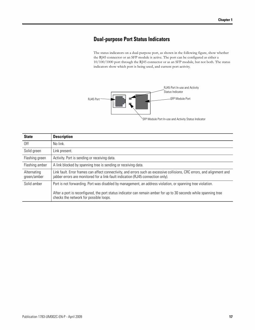
Dual-purpose Port Status Indicators
The status indicators on a dual-purpose port, as shown in the following figure, show whether the RJ45 connector or an SFP module is active. The port can be configured as either a 10/100/1000 port through the RJ45 connector or as an SFP module, but not both. The status indicators show which port is being used, and current port activity.
State Description
Off No link.
Solid green Link present.
Flashing green Activity. Port is sending or receiving data.
Flashing amber A link blocked by spanning tree is sending or receiving data.
Alternating green/amber
Link fault. Error frames can affect connectivity, and errors such as excessive collisions, CRC errors, and alignment and jabber errors are monitored for a link-fault indication (RJ45 connection only).
Solid amber Port is not forwarding. Port was disabled by management, an address violation, or spanning tree violation.
After a port is reconfigured, the port status indicator can remain amber for up to 30 seconds while spanning tree checks the network for possible loops.
RJ45 Port In-use and Activity Status Indicator
SFP Module Port In-use and Activity Status Indicator
SFP Module PortRJ45 Port
Publication 1783-UM002C-EN-P - April 2009 17
Chapter 1
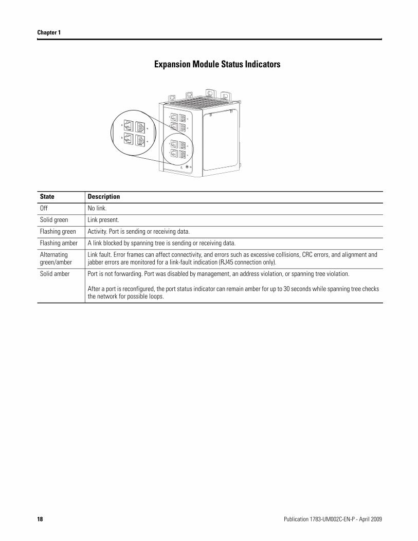
Expansion Module Status Indicators
State Description
Off No link.
Solid green Link present.
Flashing green Activity. Port is sending or receiving data.
Flashing amber A link blocked by spanning tree is sending or receiving data.
Alternating green/amber
Link fault. Error frames can affect connectivity, and errors such as excessive collisions, CRC errors, and alignment and jabber errors are monitored for a link-fault indication (RJ45 connection only).
Solid amber Port is not forwarding. Port was disabled by management, an address violation, or spanning tree violation.
After a port is reconfigured, the port status indicator can remain amber for up to 30 seconds while spanning tree checks the network for possible loops.
18 Publication 1783-UM002C-EN-P - April 2009
Chapter 1
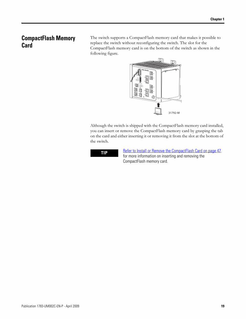
CompactFlash Memory Card
The switch supports a CompactFlash memory card that makes it possible to replace the switch without reconfiguring the switch. The slot for the CompactFlash memory card is on the bottom of the switch as shown in the following figure.
Although the switch is shipped with the CompactFlash memory card installed, you can insert or remove the CompactFlash memory card by grasping the tab on the card and either inserting it or removing it from the slot at the bottom of the switch.
TIP Refer to Install or Remove the CompactFlash Card on page 47. for more information on inserting and removing the CompactFlash memory card.
VRT
AA
31792-M
Publication 1783-UM002C-EN-P - April 2009 19

Chapter 1
Notes:
20 Publication 1783-UM002C-EN-P - April 2009
Chapter 2
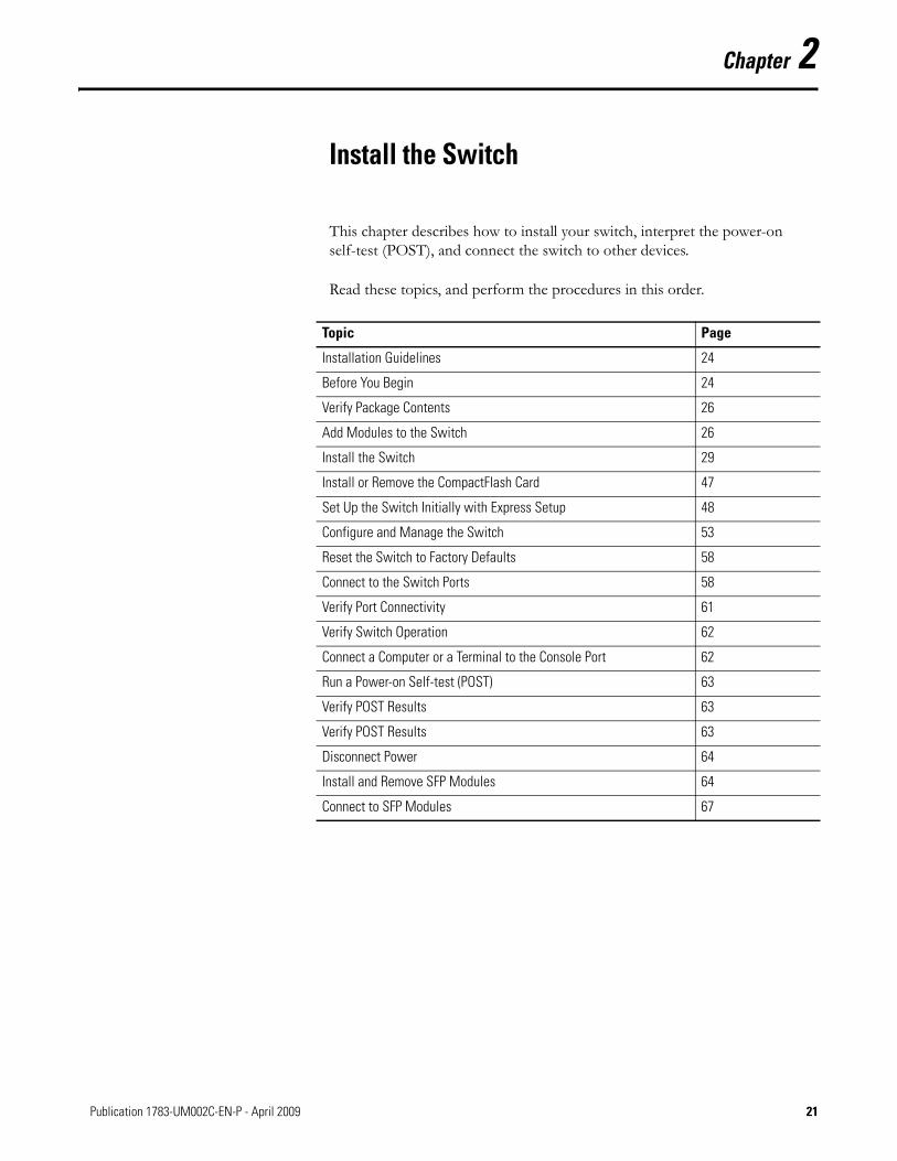
Install the Switch
This chapter describes how to install your switch, interpret the power-on self-test (POST), and connect the switch to other devices.
Read these topics, and perform the procedures in this order.
Topic Page
Installation Guidelines 24
Before You Begin 24
Verify Package Contents 26
Add Modules to the Switch 26
Install the Switch 29
Install or Remove the CompactFlash Card 47
Set Up the Switch Initially with Express Setup 48
Configure and Manage the Switch 53
Reset the Switch to Factory Defaults 58
Connect to the Switch Ports 58
Verify Port Connectivity 61
Verify Switch Operation 62
Connect a Computer or a Terminal to the Console Port 62
Run a Power-on Self-test (POST) 63
Verify POST Results 63
Verify POST Results 63
Disconnect Power 64
Install and Remove SFP Modules 64
Connect to SFP Modules 67
21Publication 1783-UM002C-EN-P - April 2009 21
Chapter 2
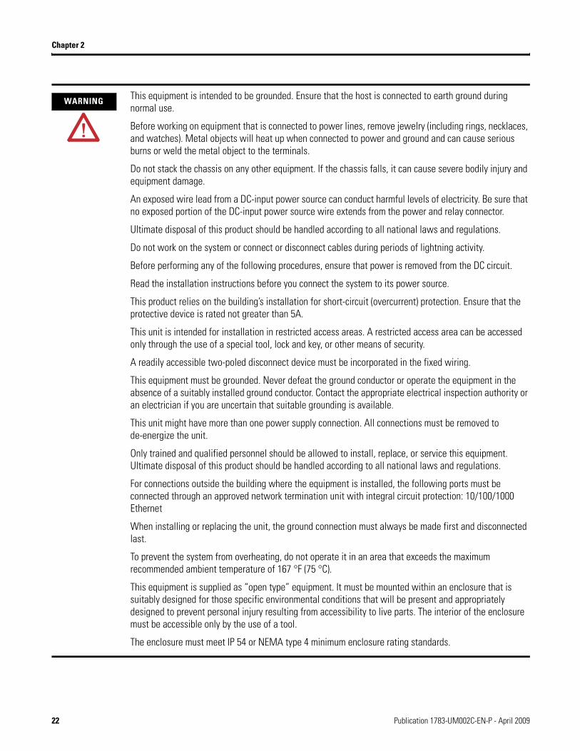
WARNING This equipment is intended to be grounded. Ensure that the host is connected to earth ground during normal use.
Before working on equipment that is connected to power lines, remove jewelry (including rings, necklaces, and watches). Metal objects will heat up when connected to power and ground and can cause serious burns or weld the metal object to the terminals.
Do not stack the chassis on any other equipment. If the chassis falls, it can cause severe bodily injury and equipment damage.
An exposed wire lead from a DC-input power source can conduct harmful levels of electricity. Be sure that no exposed portion of the DC-input power source wire extends from the power and relay connector.
Ultimate disposal of this product should be handled according to all national laws and regulations.
Do not work on the system or connect or disconnect cables during periods of lightning activity.
Before performing any of the following procedures, ensure that power is removed from the DC circuit.
Read the installation instructions before you connect the system to its power source.
This product relies on the building’s installation for short-circuit (overcurrent) protection. Ensure that the protective device is rated not greater than 5A.
This unit is intended for installation in restricted access areas. A restricted access area can be accessed only through the use of a special tool, lock and key, or other means of security.
A readily accessible two-poled disconnect device must be incorporated in the fixed wiring.
This equipment must be grounded. Never defeat the ground conductor or operate the equipment in the absence of a suitably installed ground conductor. Contact the appropriate electrical inspection authority or an electrician if you are uncertain that suitable grounding is available.
This unit might have more than one power supply connection. All connections must be removed to de-energize the unit.
Only trained and qualified personnel should be allowed to install, replace, or service this equipment. Ultimate disposal of this product should be handled according to all national laws and regulations.
For connections outside the building where the equipment is installed, the following ports must be connected through an approved network termination unit with integral circuit protection: 10/100/1000 Ethernet
When installing or replacing the unit, the ground connection must always be made first and disconnected last.
To prevent the system from overheating, do not operate it in an area that exceeds the maximum recommended ambient temperature of 167 °F (75 °C).
This equipment is supplied as “open type” equipment. It must be mounted within an enclosure that is suitably designed for those specific environmental conditions that will be present and appropriately designed to prevent personal injury resulting from accessibility to live parts. The interior of the enclosure must be accessible only by the use of a tool.
The enclosure must meet IP 54 or NEMA type 4 minimum enclosure rating standards.
22 Publication 1783-UM002C-EN-P - April 2009
Chapter 2
WARNING This equipment is intended to be grounded to comply with emission and immunity requirements. Ensure that the switch functional ground lug is connected to earth ground during normal use.
When used in a Class I, Division 2, hazardous location, this equipment must be mounted in a suitable enclosure with proper wiring method, for all power, input and output wiring, that complies with the governing electrical codes and in accordance with the authority having jurisdiction over Class I, Division 2 installations.
Use twisted-pair supply wires suitable for 30 °C (86 °F) above surrounding ambient temperature outside the enclosure.
This equipment is intended for use in a Pollution Degree 2 industrial environment, in overvoltage Category II applications (as defined in IEC publication 60664-1), and at altitudes up to 2000 m (6,561.68 ft) without derating.
Installation of the equipment must comply with local and national electrical codes.
To prevent airflow restriction, allow clearance around the ventilation openings to be at least 105 mm (4.13 in.).
ATTENTION This equipment is only suitable for use in Class I, Division 2, Groups A, B, C, D, or non hazardous locations.
Connect the unit only to a Class 2 DC power source.
Publication 1783-UM002C-EN-P - April 2009 23
Chapter 2
Installation Guidelines When determining where to place the switch, observe these guidelines.
Environment and Enclosure Guidelines
Review these environmental guidelines before installation.
• This equipment is intended for use in a Pollution Degree 2 industrial environment, in overvoltage Category II applications (as defined in IEC publication 60664-1), at altitudes up to 3 km (9842 ft) without derating.
• This equipment is considered Group 1, Class A industrial equipment, according to IEC/CISPR Publication 11. Without appropriate precautions, there may be potential difficulties ensuring electromagnetic compatibility in other environments due to conducted as well as radiated disturbance.
• This equipment is supplied as open-type equipment. It must be mounted within an enclosure that is suitably designed for those specific environmental conditions that will be present and appropriately designed to prevent personal injury resulting from accessibility to live parts. The enclosure must have suitable flame-retardant properties to prevent or minimize the spread of flame, complying with a flame-spread rating of 5VA, V2, V1, V0 (or equivalent) if nonmetallic. The interior of the enclosure must be accessible only by the use of a tool.
Before You Begin Keep these points in mind when installing the switch.
• Proper ESD protection is required whenever you handle this equipment. Installation and maintenance personnel should be properly grounded by using ground straps to eliminate the risk of ESD damage to the switch.
• Do not touch connectors or pins on component boards. Do not touch circuit components inside the switch. When not in use, store the equipment in appropriate static-safe packaging.
• Personnel responsible for the application of safety-related Programmable Electronic Systems (PES) shall be aware of the safety requirements in the application of the system and shall be trained in using the system.
• Unless panel-mounted, this product is grounded through the DIN rail to chassis ground. Use zinc-plated yellow-chromate steel DIN rail to assure proper grounding. The use of other DIN rail materials (such as aluminum, plastic, and so on.) that can corrode, oxidize, or are poor conductors, can result in improper or intermittent grounding. Secure the DIN rail to the mounting surface approximately every 200 mm (7.8 in.), and use end-anchors appropriately.
24 Publication 1783-UM002C-EN-P - April 2009
Chapter 2
Place the Switch
When determining where to place the switch, observe these guidelines
• Before attaching the switch to the network, first verify that the switch is operational by powering it on and running POST. Follow the procedures in the Verify Switch Operation section on page 62.
• For 10/100 ports and 10/100/1000 ports, the cable length from a switch to an attached device cannot exceed 100 m (328 ft).
• For 100BASE-FX fiber-optic ports, the cable length from a switch to an attached device cannot exceed 2 km (6562 ft).
• Operating environment is within the ranges listed in the Stratix 8000 Ethernet Managed Switch Installation Instructions, publication 1783-IN005.
• Clearance to front and rear panels meet these conditions:– Front-panel status indicators can be easily read.– Access to ports is sufficient for unrestricted cabling.– Front-panel direct current (DC) power and relay connector is within
reach of the connection to the DC power source.• Airflow around the switch and through the vents is unrestricted. To
prevent the switch from overheating, provide the following minimum clearances:– Top and bottom: 105 mm (4.13 in.)– Exposed side (not connected to the module): 90 mm (3.54 in.)– Front: 65 mm (2.56 in.)
• Temperature surrounding the unit does not exceed 75 °C (167 °F)
• Cabling is away from sources of electrical noise, such as radios, power lines, and fluorescent lighting fixtures.
ATTENTION When the switch is installed in an industrial enclosure, the temperature within the enclosure is greater than normal room temperature outside the enclosure.
The temperature inside the enclosure cannot exceed 75 oC(167 oF), the maximum ambient enclosure temperature of the switch.
Publication 1783-UM002C-EN-P - April 2009 25
Chapter 2
Verify Package Contents Carefully remove the contents from the shipping container, and check each item for damage. If any item is missing or damaged, contact your Rockwell Automation representative for assistance.
The switch is shipped with these items.
• Stratix 8000 Ethernet Managed Switches Installation Instructions, publication 1783-IN005.
• Two power and relay connectors • RJ45 to DB-9 console port adapter cable• CompactFlash card
If you want to connect a terminal to the switch console port, you need to provide an RJ45-to-DB-25 female DTE adapter. For multimode (MM) connections, you can connect a 100BASE-FX port to a port on a target device by using dual-LC connector.
The switch expansion modules are optional, and do not ship with the switch. You need to order these separately.
Add Modules to the Switch The switches can operate as standalone devices with four or eight Fast Ethernet ports, respectively. To increase the number of Fast Ethernet ports by 8 or 16, you can connect the optional expansion modules. Depending on the mix of switches and expansion modules, you can have up to 24 Fast Ethernet ports. The expansion modules cannot operate as standalone devices.
Expansion Module Configurations
To increase the number of ports, add one or two expansion modules to the switch. If you are installing only one module, it can be either an 1783-MX08T copper expansion module, or a 1783-MX08F fiber expansion module. If you are installing two modules, the first must be an 1783-MX08T copper expansion module, and the second can be either an 1783-MX08T copper expansion module, or a 1783-MX08F fiber expansion module. You cannot add two 1783-MX08F fiber expansion modules.
IMPORTANT To connect the switch functional ground, you need a ring terminal lug (such as Thomas & Bett part number 10RCR or equivalent).
26 Publication 1783-UM002C-EN-P - April 2009
Chapter 2
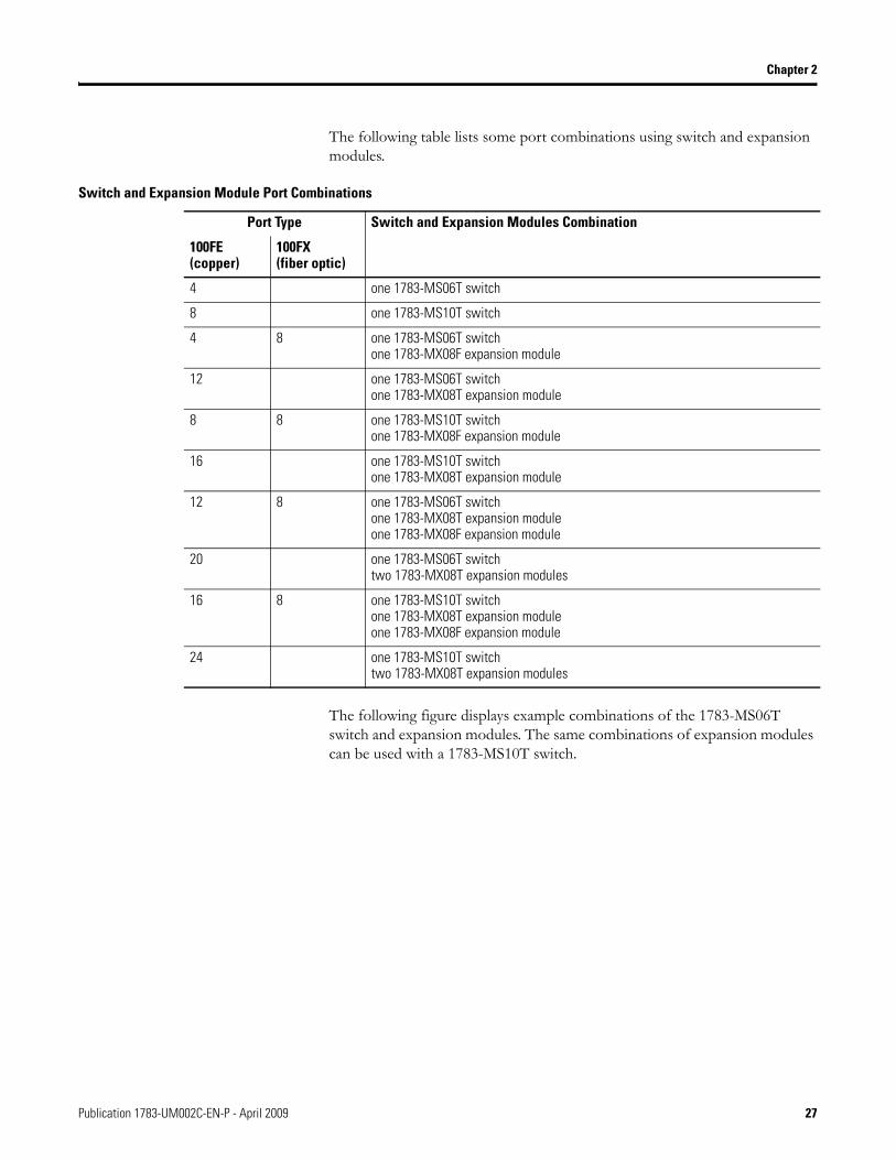
The following table lists some port combinations using switch and expansion modules.
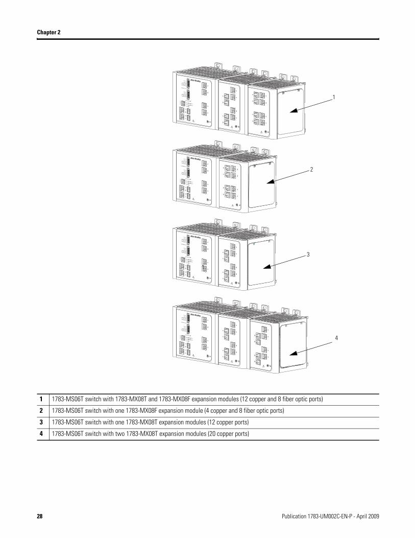
The following figure displays example combinations of the 1783-MS06T switch and expansion modules. The same combinations of expansion modules can be used with a 1783-MS10T switch.
Switch and Expansion Module Port Combinations
Port Type Switch and Expansion Modules Combination
100FE (copper)
100FX(fiber optic)
4 one 1783-MS06T switch
8 one 1783-MS10T switch
4 8 one 1783-MS06T switchone 1783-MX08F expansion module
12 one 1783-MS06T switch one 1783-MX08T expansion module
8 8 one 1783-MS10T switchone 1783-MX08F expansion module
16 one 1783-MS10T switch one 1783-MX08T expansion module
12 8 one 1783-MS06T switchone 1783-MX08T expansion moduleone 1783-MX08F expansion module
20 one 1783-MS06T switchtwo 1783-MX08T expansion modules
16 8 one 1783-MS10T switchone 1783-MX08T expansion moduleone 1783-MX08F expansion module
24 one 1783-MS10T switchtwo 1783-MX08T expansion modules
Publication 1783-UM002C-EN-P - April 2009 27
Chapter 2
1 1783-MS06T switch with 1783-MX08T and 1783-MX08F expansion modules (12 copper and 8 fiber optic ports)
2 1783-MS06T switch with one 1783-MX08F expansion module (4 copper and 8 fiber optic ports)
3 1783-MS06T switch with one 1783-MX08T expansion modules (12 copper ports)
4 1783-MS06T switch with two 1783-MX08T expansion modules (20 copper ports)
2
3
1
1
4
28 Publication 1783-UM002C-EN-P - April 2009
Chapter 2
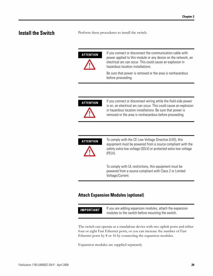
Install the Switch Perform these procedures to install the switch.
Attach Expansion Modules (optional)
The switch can operate as a standalone device with two uplink ports and either four or eight Fast Ethernet ports, or you can increase the number of Fast Ethernet ports by 8 or 16 by connecting the expansion modules.
Expansion modules are supplied separately.
ATTENTION If you connect or disconnect the communication cable with power applied to this module or any device on the network, an electrical arc can occur. This could cause an explosion in hazardous location installations.
Be sure that power is removed or the area is nonhazardous before proceeding.
ATTENTION If you connect or disconnect wiring while the field-side power is on, an electrical arc can occur. This could cause an explosion in hazardous location installations. Be sure that power is removed or the area is nonhazardous before proceeding.
ATTENTION To comply with the CE Low Voltage Directive (LVD), this equipment must be powered from a source compliant with the safety extra low voltage (SELV) or protected extra low voltage (PELV).
To comply with UL restrictions, this equipment must be powered from a source compliant with Class 2 or Limited Voltage/Current.
IMPORTANT If you are adding expansion modules, attach the expansion modules to the switch before mounting the switch.
Publication 1783-UM002C-EN-P - April 2009 29
Chapter 2
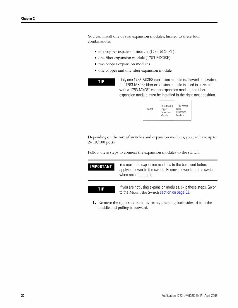
You can install one or two expansion modules, limited to these four combinations:
• one copper expansion module (1783-MX08T)• one fiber expansion module (1783-MX08F)• two copper expansion modules• one copper and one fiber expansion module
Depending on the mix of switches and expansion modules, you can have up to 24 10/100 ports.
Follow these steps to connect the expansion modules to the switch.
1. Remove the right side panel by firmly grasping both sides of it in the middle and pulling it outward.
TIP Only one 1783-MX08F expansion module is allowed per switch. If a 1783-MX08F fiber expansion module is used in a system with a 1783-MX08T copper expansion module, the fiber expansion module must be installed in the right-most position.
IMPORTANT You must add expansion modules to the base unit before applying power to the switch. Remove power from the switch when reconfiguring it.
TIP If you are not using expansion modules, skip these steps. Go on to the Mount the Switch section on page 32.
Switch1783-MX08T Copper Expansion Module
1783-MX08F Fiber Expansion Module
30 Publication 1783-UM002C-EN-P - April 2009
Chapter 2
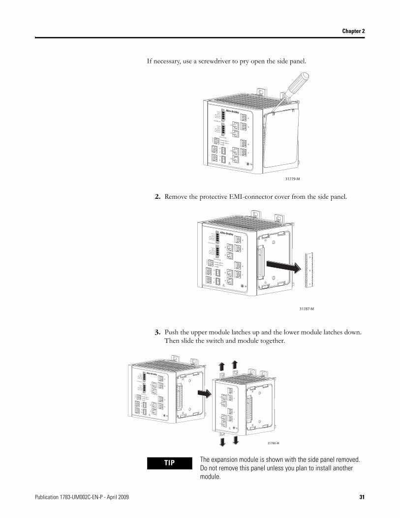
If necessary, use a screwdriver to pry open the side panel.
2. Remove the protective EMI-connector cover from the side panel.
3. Push the upper module latches up and the lower module latches down. Then slide the switch and module together.
31779-M
31787-M
31780-M
TIP The expansion module is shown with the side panel removed. Do not remove this panel unless you plan to install another module.
Publication 1783-UM002C-EN-P - April 2009 31
Chapter 2
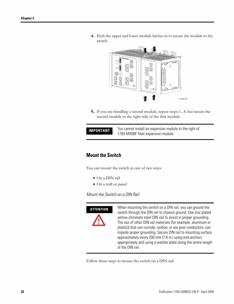
4. Push the upper and lower module latches in to secure the module to the switch.
5. If you are installing a second module, repeat steps 1...4, but secure the second module to the right side of the first module.
Mount the Switch
You can mount the switch in one of two ways:
• On a DIN rail• On a wall or panel
Mount the Switch on a DIN Rail
Follow these steps to mount the switch on a DIN rail.
IMPORTANT You cannot install an expansion module to the right of 1783-MX08F fiber expansion module.
ATTENTION When mounting the switch on a DIN rail, you can ground the switch through the DIN rail to chassis ground. Use zinc plated yellow-chromate steel DIN rail to assist in proper grounding. The use of other DIN rail materials (for example, aluminum or plastic)) that can corrode, oxidize, or are poor conductors, can impede proper grounding. Secure DIN rail to mounting surface approximately every 200 mm (7.8 in.) using end-anchors appropriately and using a washer plate along the entire length of the DIN rail.
31781-M
32 Publication 1783-UM002C-EN-P - April 2009
Chapter 2
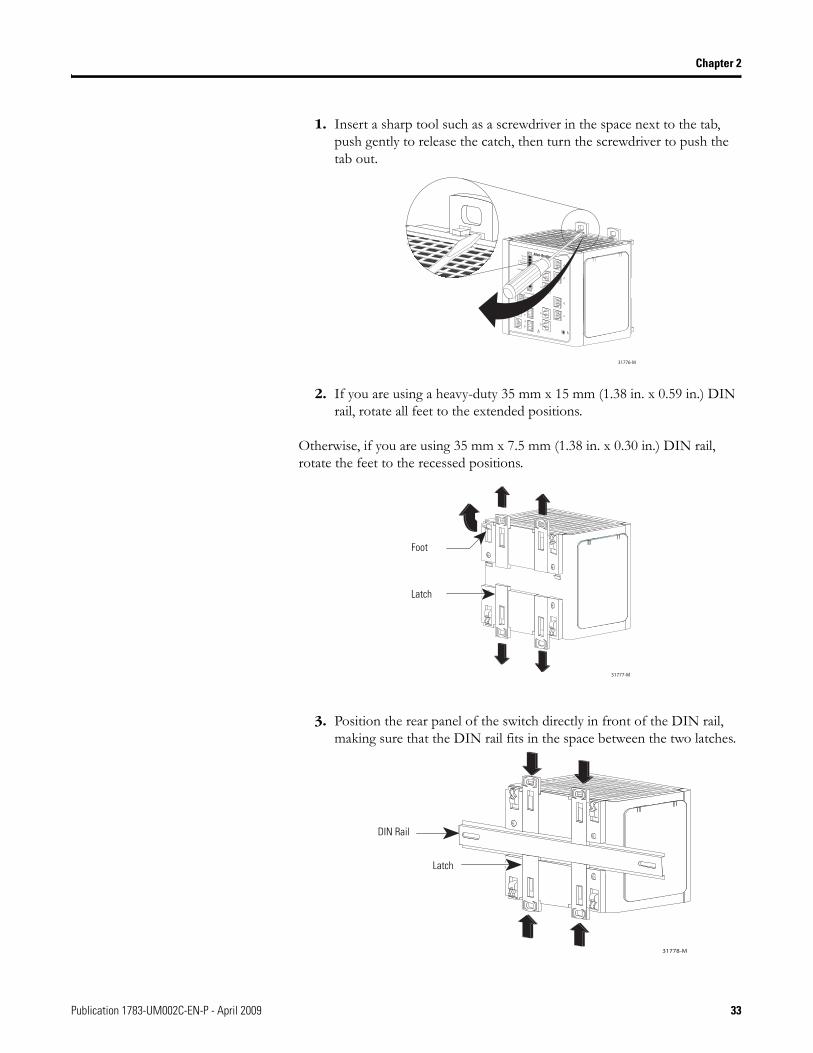
1. Insert a sharp tool such as a screwdriver in the space next to the tab, push gently to release the catch, then turn the screwdriver to push the tab out.
2. If you are using a heavy-duty 35 mm x 15 mm (1.38 in. x 0.59 in.) DIN rail, rotate all feet to the extended positions.
Otherwise, if you are using 35 mm x 7.5 mm (1.38 in. x 0.30 in.) DIN rail, rotate the feet to the recessed positions.
3. Position the rear panel of the switch directly in front of the DIN rail, making sure that the DIN rail fits in the space between the two latches.
31776-M
31777-M
Latch
Foot
31778-M
Latch
DIN Rail
Publication 1783-UM002C-EN-P - April 2009 33

Chapter 2
4. Push the DIN rail latches in after the switch is over the DIN rail to secure the switch to the rail.
5. Ground the switch.
Refer to Ground the Switch on page 38.
6. Wire the switch.
Refer to Wire the DC Power Source on page 40.
34 Publication 1783-UM002C-EN-P - April 2009
Chapter 2
Install the Switch on a Wall or Panel
The switch can be installed on a wall or a panel. To attach the switch to a wall or a panel, follow these steps.
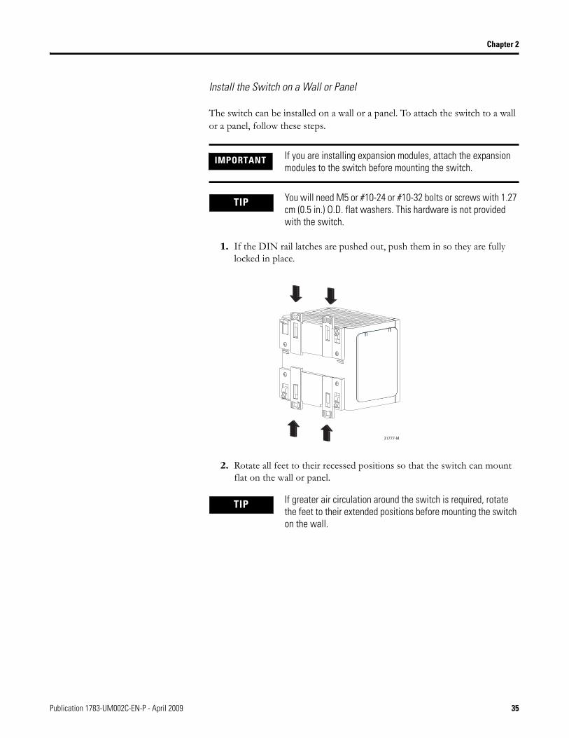
1. If the DIN rail latches are pushed out, push them in so they are fully locked in place.
2. Rotate all feet to their recessed positions so that the switch can mount flat on the wall or panel.
IMPORTANT If you are installing expansion modules, attach the expansion modules to the switch before mounting the switch.
TIP You will need M5 or #10-24 or #10-32 bolts or screws with 1.27 cm (0.5 in.) O.D. flat washers. This hardware is not provided with the switch.
31777-M
TIP If greater air circulation around the switch is required, rotate the feet to their extended positions before mounting the switch on the wall.
Publication 1783-UM002C-EN-P - April 2009 35
Chapter 2
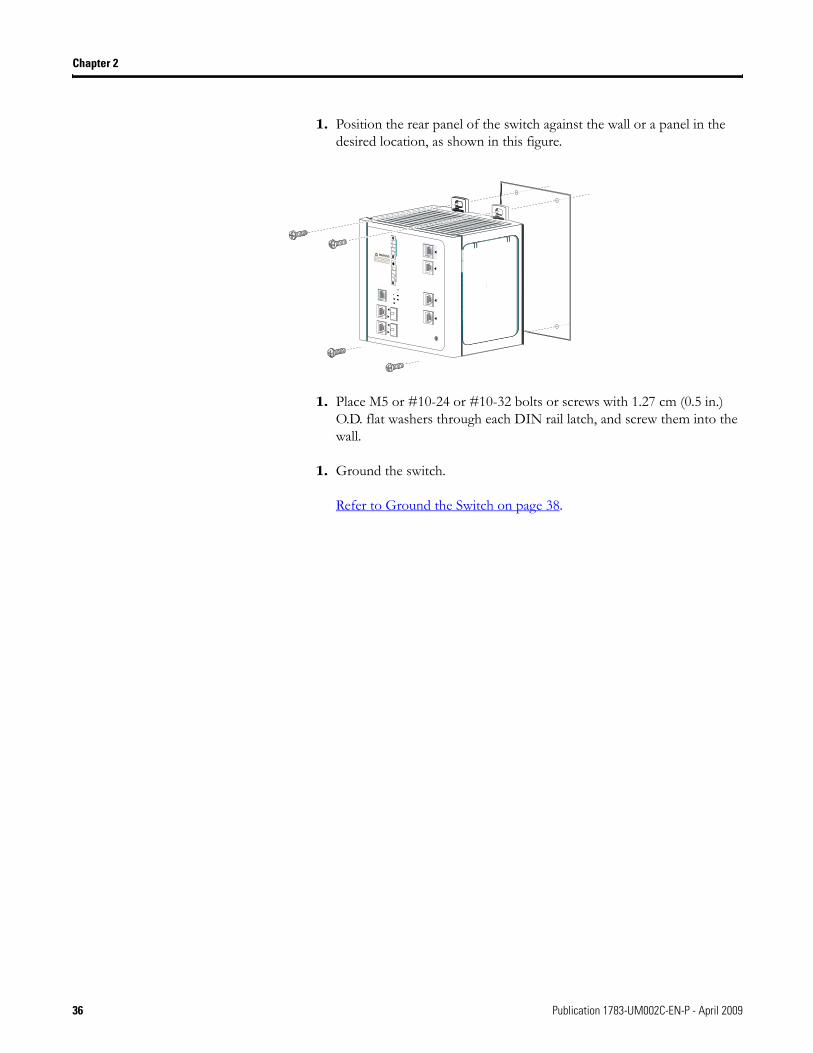
1. Position the rear panel of the switch against the wall or a panel in the desired location, as shown in this figure.
1. Place M5 or #10-24 or #10-32 bolts or screws with 1.27 cm (0.5 in.) O.D. flat washers through each DIN rail latch, and screw them into the wall.
1. Ground the switch.
Refer to Ground the Switch on page 38.
1
3
4
1
2
tsylataC ocsiC
CDV42( A rwP
)CDV 84 ro
ntR A
42( B rwPro CDV
84 DV )C
ntR B
pxEputeS sser
tsyS me
mralA
teS pu
A rwP
B rwP
ojaM lA r mra
M oni lA r mra
tinu sihTim thg ah ev erom th na eno
wop re roc .d oT re t ecud eh ris o k fcele tri s c coh d k csi enno tc owt ehtwop re roc sd feb ero ivres
.tinu gnic
GNINRAW!
36 Publication 1783-UM002C-EN-P - April 2009
P
Chapter 2
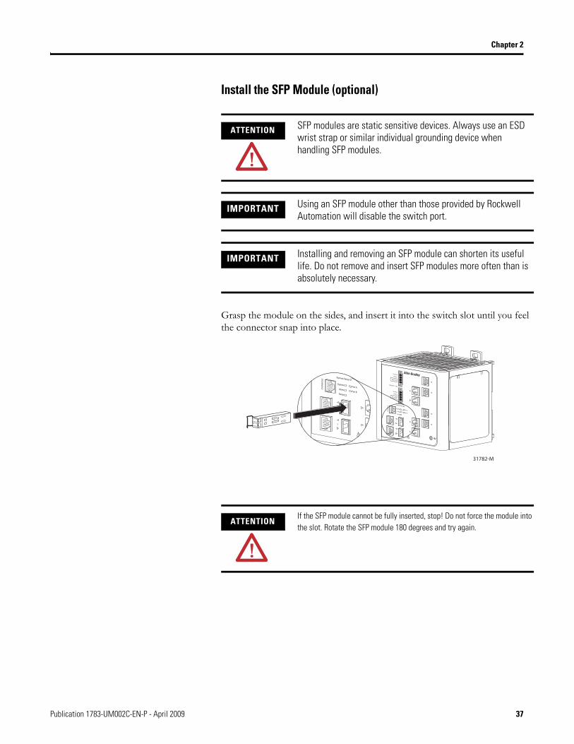
Install the SFP Module (optional)
Grasp the module on the sides, and insert it into the switch slot until you feel the connector snap into place.
ATTENTION SFP modules are static sensitive devices. Always use an ESD wrist strap or similar individual grounding device when handling SFP modules.
IMPORTANT Using an SFP module other than those provided by Rockwell Automation will disable the switch port.
IMPORTANT Installing and removing an SFP module can shorten its useful life. Do not remove and insert SFP modules more often than is absolutely necessary.
ATTENTIONIf the SFP module cannot be fully inserted, stop! Do not force the module into the slot. Rotate the SFP module 180 degrees and try again.
31782-M
ublication 1783-UM002C-EN-P - April 2009 37
Chapter 2
Ground the Switch
Follow these steps to connect the switch to a protective ground.
1. Use a standard Phillips screwdriver or a ratcheting-torque screwdriver with a Phillips head to remove the ground screw from the front panel of the switch.
2. Store the ground screw for later use.
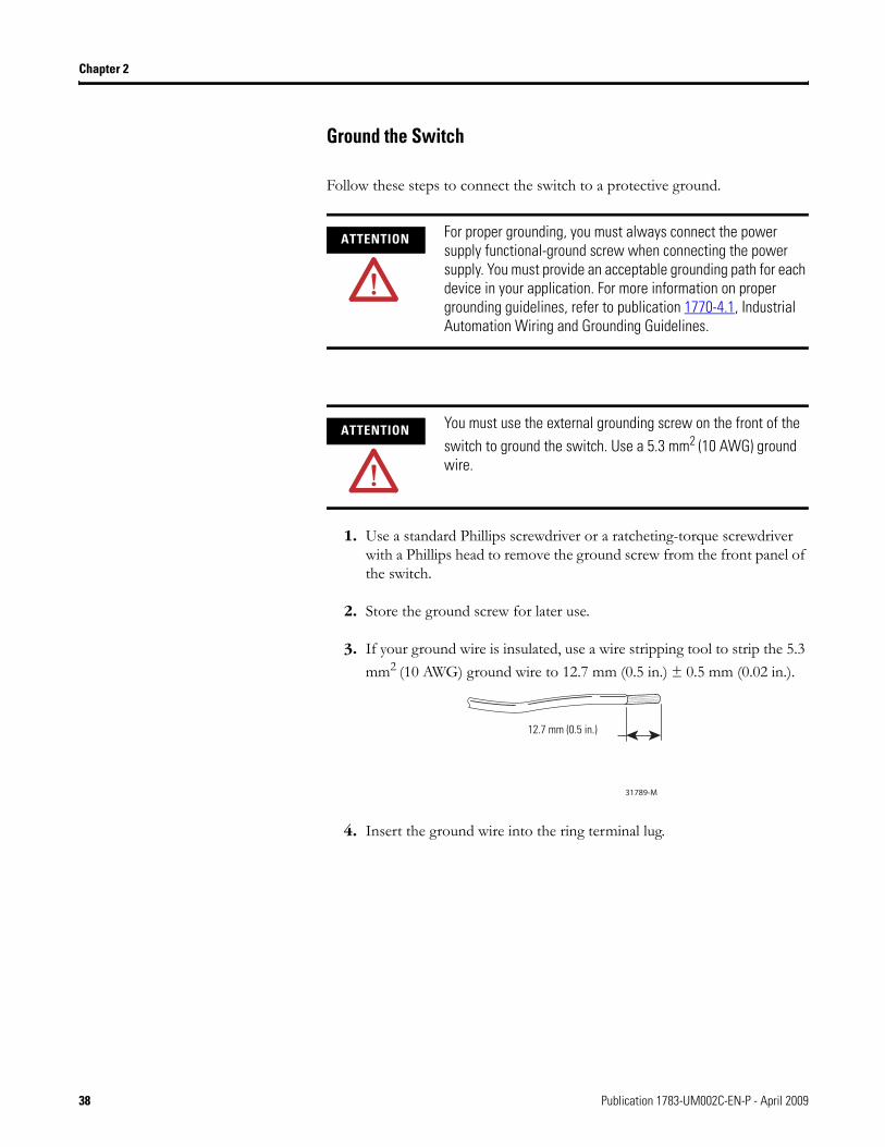
3. If your ground wire is insulated, use a wire stripping tool to strip the 5.3 mm2 (10 AWG) ground wire to 12.7 mm (0.5 in.) ± 0.5 mm (0.02 in.).
4. Insert the ground wire into the ring terminal lug.
ATTENTION For proper grounding, you must always connect the power supply functional-ground screw when connecting the power supply. You must provide an acceptable grounding path for each device in your application. For more information on proper grounding guidelines, refer to publication 1770-4.1, Industrial Automation Wiring and Grounding Guidelines.
ATTENTION You must use the external grounding screw on the front of the switch to ground the switch. Use a 5.3 mm2 (10 AWG) ground wire.
31789-M
12.7 mm (0.5 in.)
38 Publication 1783-UM002C-EN-P - April 2009
Chapter 2
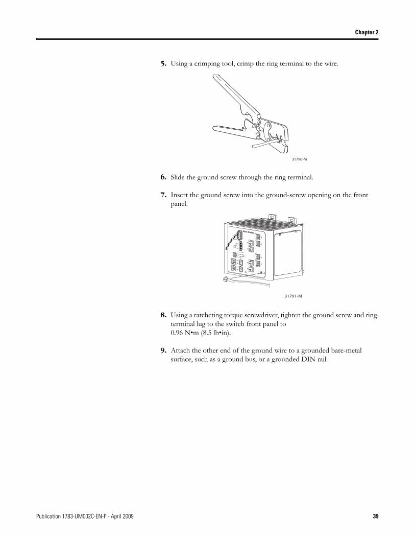
5. Using a crimping tool, crimp the ring terminal to the wire.
6. Slide the ground screw through the ring terminal.
7. Insert the ground screw into the ground-screw opening on the front panel.
8. Using a ratcheting torque screwdriver, tighten the ground screw and ring terminal lug to the switch front panel to 0.96 N•m (8.5 lb•in).
9. Attach the other end of the ground wire to a grounded bare-metal surface, such as a ground bus, or a grounded DIN rail.
31790-M
VRT
AA
31791-M
Publication 1783-UM002C-EN-P - April 2009 39
Chapter 2
Wire the DC Power Source
Follow these steps to prepare the DC power cable.
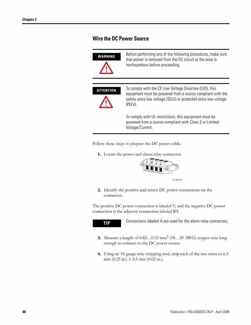
1. Locate the power and alarm relay connector.
2. Identify the positive and return DC power connections on the connector.
The positive DC power connection is labeled V, and the negative DC power connection is the adjacent connection labeled RT.
3. Measure a length of 0.82…0.52 mm2 (18…20 AWG) copper wire long enough to connect to the DC power source.
4. Using an 18-gauge wire-stripping tool, strip each of the two wires to 6.3 mm (0.25 in.) ± 0.5 mm (0.02 in.).
WARNING Before performing any of the following procedures, make sure that power is removed from the DC circuit or the area is nonhazardous before proceeding.
ATTENTION To comply with the CE Low Voltage Directive (LVD), this equipment must be powered from a source compliant with the safety extra low voltage (SELV) or protected extra low voltage (PELV).
To comply with UL restrictions, this equipment must be powered from a source compliant with Class 2 or Limited Voltage/Current.
TIP Connections labeled A are used for the alarm relay connectors.
RT AVA
31783-M
40 Publication 1783-UM002C-EN-P - April 2009
Chapter 2
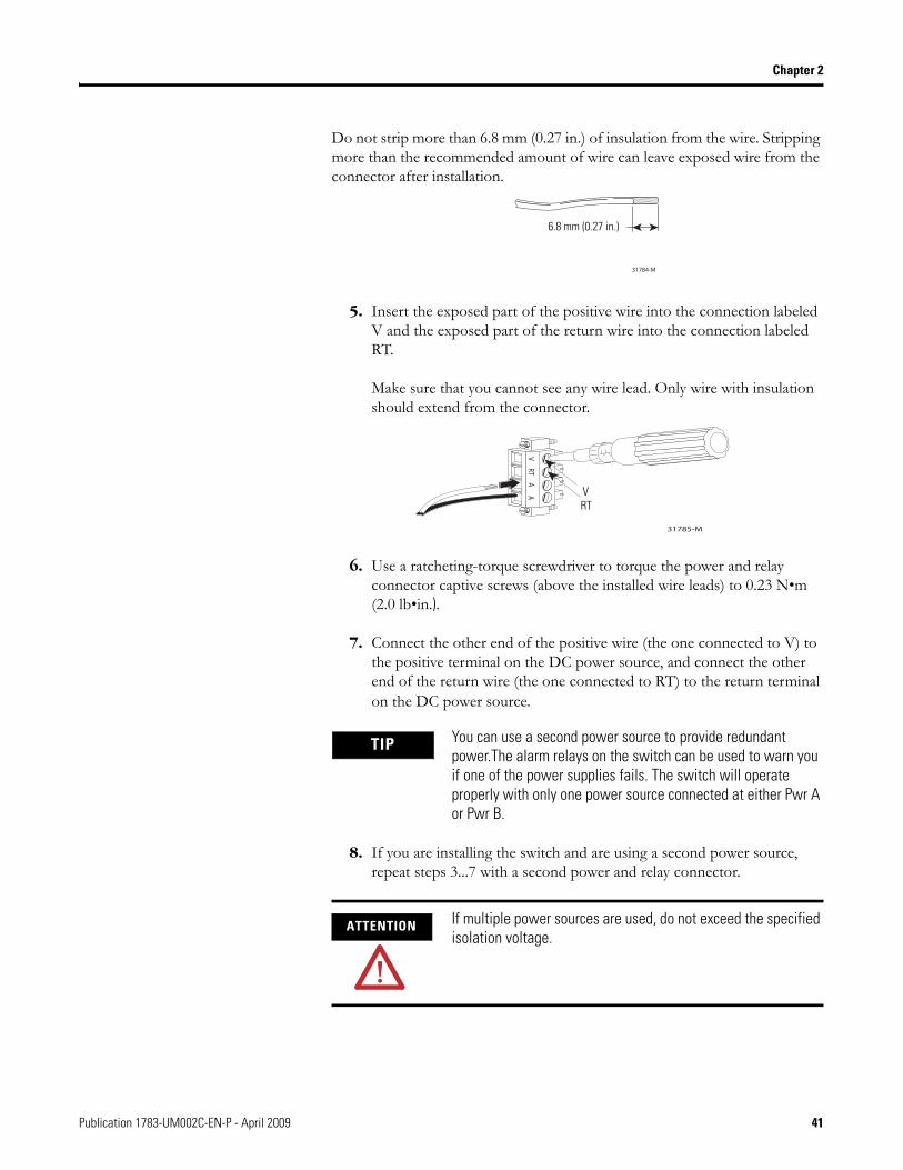
Do not strip more than 6.8 mm (0.27 in.) of insulation from the wire. Stripping more than the recommended amount of wire can leave exposed wire from the connector after installation.
5. Insert the exposed part of the positive wire into the connection labeled V and the exposed part of the return wire into the connection labeled RT.
Make sure that you cannot see any wire lead. Only wire with insulation should extend from the connector.
6. Use a ratcheting-torque screwdriver to torque the power and relay connector captive screws (above the installed wire leads) to 0.23 N•m (2.0 lb•in.).
7. Connect the other end of the positive wire (the one connected to V) to the positive terminal on the DC power source, and connect the other end of the return wire (the one connected to RT) to the return terminal on the DC power source.
8. If you are installing the switch and are using a second power source, repeat steps 3...7 with a second power and relay connector.
TIP You can use a second power source to provide redundant power.The alarm relays on the switch can be used to warn you if one of the power supplies fails. The switch will operate properly with only one power source connected at either Pwr A or Pwr B.
ATTENTION If multiple power sources are used, do not exceed the specified isolation voltage.
31784-M
6.8 mm (0.27 in.)
VRT
AA
31785-M
VRT
Publication 1783-UM002C-EN-P - April 2009 41
Chapter 2
Attach the Power and Relay Connector
Follow these steps to connect the DC power and relay connector to the switch:.
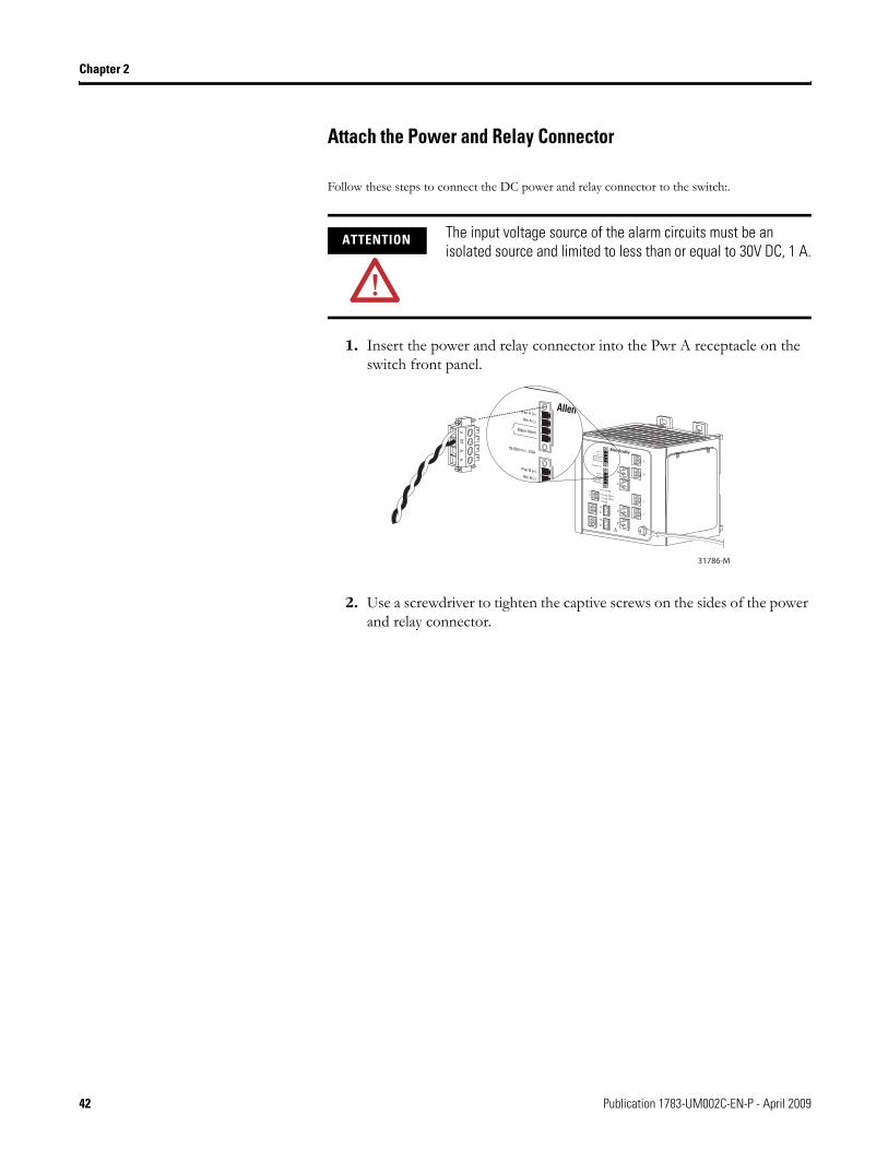
1. Insert the power and relay connector into the Pwr A receptacle on the switch front panel.
2. Use a screwdriver to tighten the captive screws on the sides of the power and relay connector.
ATTENTION The input voltage source of the alarm circuits must be an isolated source and limited to less than or equal to 30V DC, 1 A.
VRT
AA
31786-M
42 Publication 1783-UM002C-EN-P - April 2009
Chapter 2
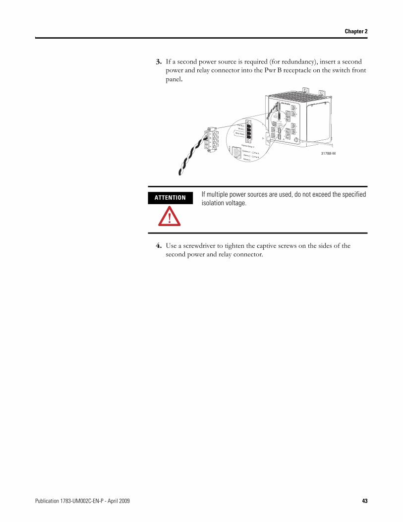
3. If a second power source is required (for redundancy), insert a second power and relay connector into the Pwr B receptacle on the switch front panel.
4. Use a screwdriver to tighten the captive screws on the sides of the second power and relay connector.
ATTENTION If multiple power sources are used, do not exceed the specified isolation voltage.
VRT
AA
31788-M
VRT
AA
Publication 1783-UM002C-EN-P - April 2009 43
Chapter 2
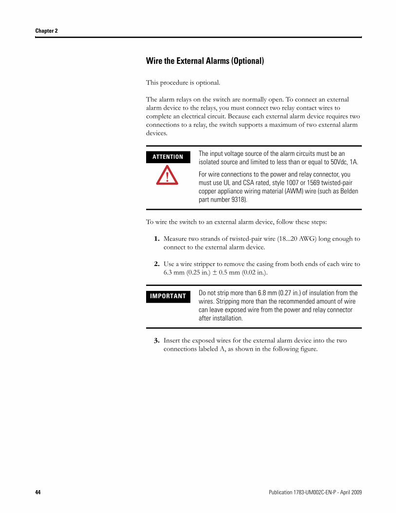
Wire the External Alarms (Optional)
This procedure is optional.
The alarm relays on the switch are normally open. To connect an external alarm device to the relays, you must connect two relay contact wires to complete an electrical circuit. Because each external alarm device requires two connections to a relay, the switch supports a maximum of two external alarm devices.
To wire the switch to an external alarm device, follow these steps:
1. Measure two strands of twisted-pair wire (18...20 AWG) long enough to connect to the external alarm device.
2. Use a wire stripper to remove the casing from both ends of each wire to 6.3 mm (0.25 in.) ± 0.5 mm (0.02 in.).
3. Insert the exposed wires for the external alarm device into the two connections labeled A, as shown in the following figure.
ATTENTION The input voltage source of the alarm circuits must be an isolated source and limited to less than or equal to 50Vdc, 1A.
For wire connections to the power and relay connector, you must use UL and CSA rated, style 1007 or 1569 twisted-pair copper appliance wiring material (AWM) wire (such as Belden part number 9318).
IMPORTANT Do not strip more than 6.8 mm (0.27 in.) of insulation from the wires. Stripping more than the recommended amount of wire can leave exposed wire from the power and relay connector after installation.
44 Publication 1783-UM002C-EN-P - April 2009
Chapter 2
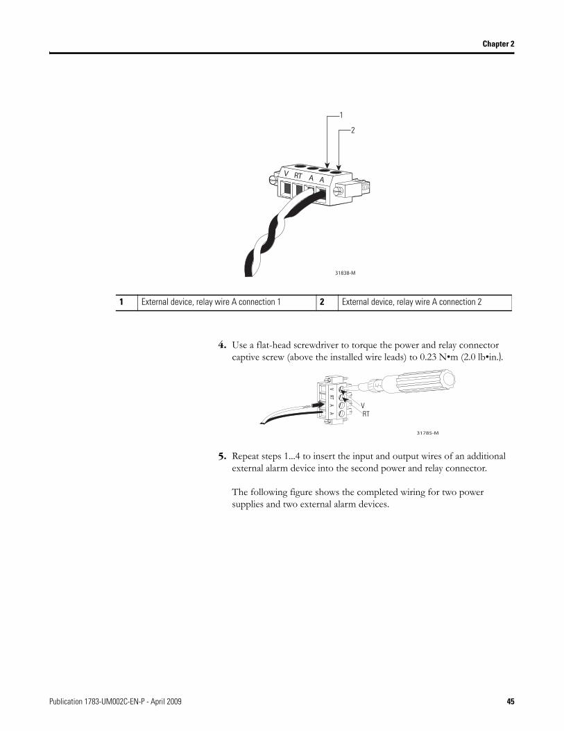
4. Use a flat-head screwdriver to torque the power and relay connector captive screw (above the installed wire leads) to 0.23 N•m (2.0 lb•in.).
5. Repeat steps 1...4 to insert the input and output wires of an additional external alarm device into the second power and relay connector.
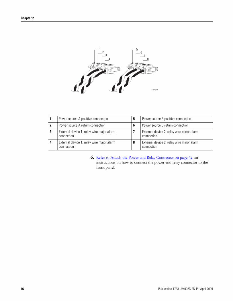
The following figure shows the completed wiring for two power supplies and two external alarm devices.
1 External device, relay wire A connection 1 2 External device, relay wire A connection 2
1
2
VRT
AA
31785-M
VRT
Publication 1783-UM002C-EN-P - April 2009 45
Chapter 2
6. Refer to Attach the Power and Relay Connector on page 42 for instructions on how to connect the power and relay connector to the front panel.
1 Power source A positive connection 5 Power source B positive connection
2 Power source A return connection 6 Power source B return connection
3 External device 1, relay wire major alarm connection
7 External device 2, relay wire minor alarm connection
4 External device 1, relay wire major alarm connection
8 External device 2, relay wire minor alarm connection
12
34
56
78
46 Publication 1783-UM002C-EN-P - April 2009
Chapter 2
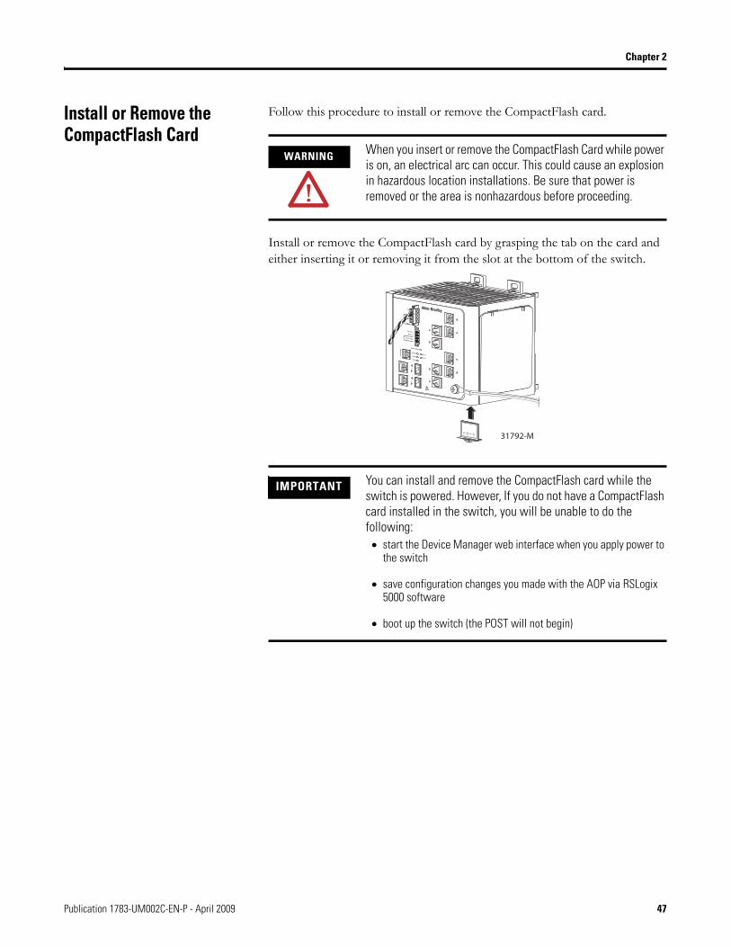
Install or Remove the CompactFlash Card
Follow this procedure to install or remove the CompactFlash card.
Install or remove the CompactFlash card by grasping the tab on the card and either inserting it or removing it from the slot at the bottom of the switch.
WARNING When you insert or remove the CompactFlash Card while power is on, an electrical arc can occur. This could cause an explosion in hazardous location installations. Be sure that power is removed or the area is nonhazardous before proceeding.
IMPORTANT You can install and remove the CompactFlash card while the switch is powered. However, If you do not have a CompactFlash card installed in the switch, you will be unable to do the following:• start the Device Manager web interface when you apply power to
the switch
• save configuration changes you made with the AOP via RSLogix 5000 software
• boot up the switch (the POST will not begin)
VRT
AA
31792-M
Publication 1783-UM002C-EN-P - April 2009 47
Chapter 2
Set Up the Switch Initially with Express Setup
When you first set up the switch, use Express Setup to enter the initial IP address. Doing this enables the switch to be used as a managed switch. You can then access the switch through the IP address for additional configuration.
You need this equipment to set up the switch:
• A personal computer with Windows 2000, Windows Vista, Windows 2003, or XP operating system installed.
• A web browser (Internet Explorer 6.0, Internet Explorer 7.0, or Firefox 2.0) with JavaScript enabled.
• A straight-through or crossover Category 5 Ethernet cable to connect your personal computer to the switch.
Do the following to configure your computer:
• Disable any wireless interface running on your personal computer.• Disable other networks in your system.• Set up the DHCP protocol for Auto IP, not static.• Disable the static DNS server.• Disable browser proxy settings.
Typically, browser settings are located in Tools>Internet Options>Connections>LAN Settings.
Follow these steps to run Express Setup.
1. Make sure that at least one switch Ethernet port is available for Express Setup.
During Express Setup, the switch acts as a DHCP server. If your personal computer has a static IP address, change your personal computer settings before you begin to temporarily use DHCP.
2. Apply power to the switch.
When the switch powers on, it begins the power-on self-test (POST). During POST, the status indicators flash while a series of tests verify that the switch functions properly. Wait for the switch to complete POST, which takes approximately 3 minutes.
3. Make sure that POST has completed by verifying that the EIP Mod and Setup status indicators are flashing green.
IMPORTANT Do not use the console port for Express Setup.
48 Publication 1783-UM002C-EN-P - April 2009
Chapter 2
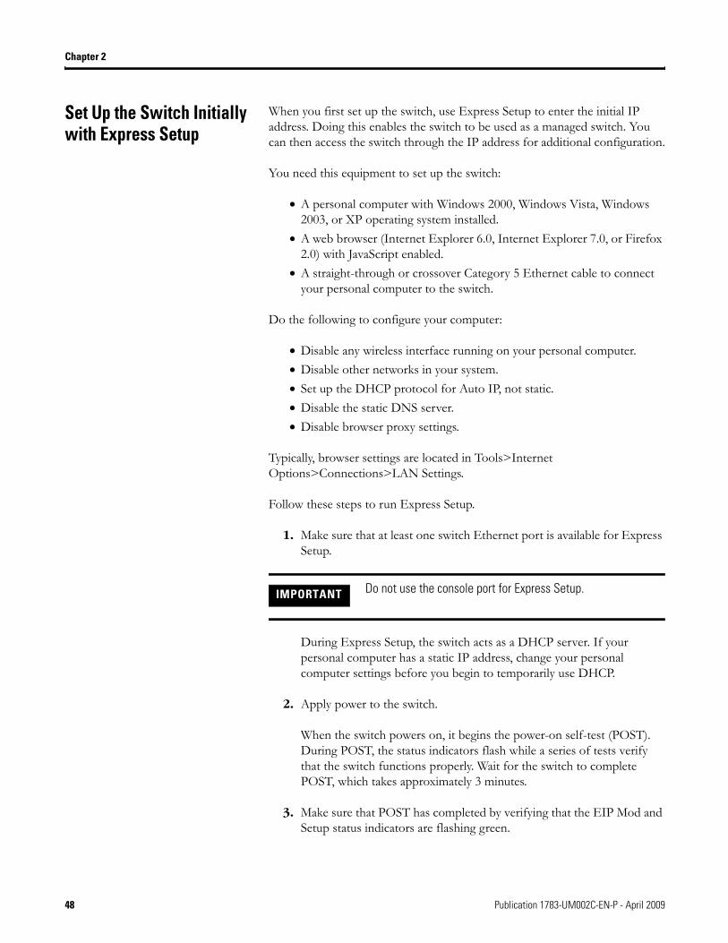
If the switch fails POST, the EIP Mod status indicator turns red.
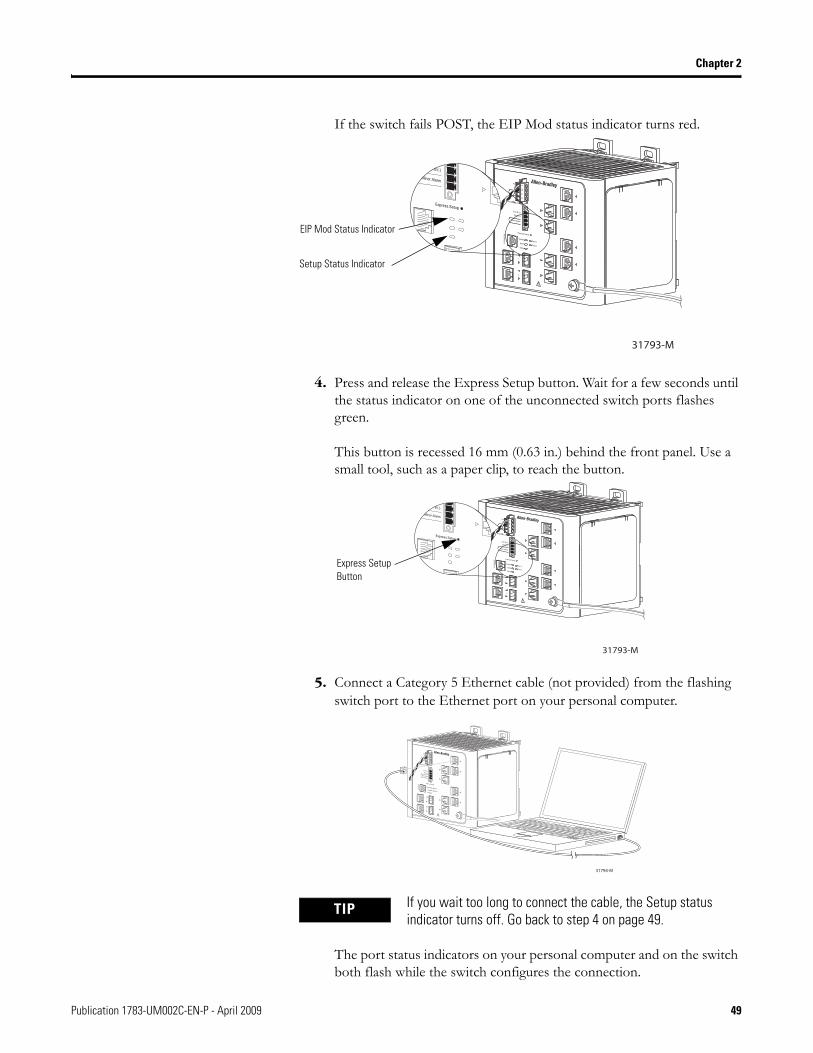
4. Press and release the Express Setup button. Wait for a few seconds until the status indicator on one of the unconnected switch ports flashes green.
This button is recessed 16 mm (0.63 in.) behind the front panel. Use a small tool, such as a paper clip, to reach the button.
5. Connect a Category 5 Ethernet cable (not provided) from the flashing switch port to the Ethernet port on your personal computer.
The port status indicators on your personal computer and on the switch both flash while the switch configures the connection.
TIP If you wait too long to connect the cable, the Setup status indicator turns off. Go back to step 4 on page 49.
VRT
AA
31793-M
EIP Mod Status Indicator
Setup Status Indicator
VRT
AA
31793-M
Express Setup Button
VRT
AA
31794-M
Publication 1783-UM002C-EN-P - April 2009 49
Chapter 2
6. While the Setup status indicator flashes green, start an Internet browser session on the personal computer.
The switch prompts you for the default switch username and password.
7. Leave the username field blank.
8. Enter the default switch password, switch.
The Express Setup dialog box automatically appears.
9. If the window does not appear, do the following:
• enter the URL of a well-known website in your browser to be sure the browser is working correctly.
Your browser will then automatically be directed to the Express Setup web page.
• verify that any proxy settings or pop-up blockers are disabled on your browser.
• verify that any wireless interface is disabled on your personal computer. .
TIP You may also enter the URL http://169.254.0.1/express-setup.htm to access the Express Setup page directly.
50 Publication 1783-UM002C-EN-P - April 2009
Chapter 2
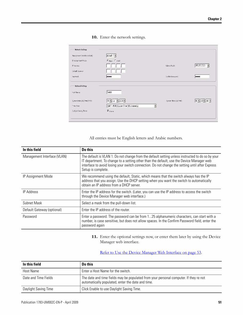
10. Enter the network settings.
All entries must be English letters and Arabic numbers.
11. Enter the optional settings now, or enter them later by using the Device Manager web interface.
Refer to Use the Device Manager Web Interface on page 53.
In this field Do this
Management Interface (VLAN) The default is VLAN 1. Do not change from the default setting unless instructed to do so by your IT department. To change to a setting other than the default, use the Device Manager web interface to avoid losing your switch connection. Do not change the setting until after Express Setup is complete.
IP Assignment Mode We recommend using the default, Static, which means that the switch always has the IP address that you assign. Use the DHCP setting when you want the switch to automatically obtain an IP address from a DHCP server.
IP Address Enter the IP address for the switch. (Later, you can use the IP address to access the switch through the Device Manager web interface.)
Subnet Mask Select a mask from the pull-down list.
Default Gateway (optional) Enter the IP address of the router.
Password Enter a password. The password can be from 1...25 alphanumeric characters, can start with a number, is case sensitive, but does not allow spaces. In the Confirm Password field, enter the password again
In this field Do this
Host Name Enter a Host Name for the switch.
Date and Time Fields The date and time fields may be populated from your personal computer. If they re not automatically populated, enter the date and time.
Daylight Saving Time Click Enable to use Daylight Saving Time.
Publication 1783-UM002C-EN-P - April 2009 51
Chapter 2
1. Click Submit to save the information that you entered and to finish the basic configuration.
• Once you click Submit, the switch initializes its configuration for typical industrial EtherNet/IP applications.The switch then re-directs you to the Device Manager web interface logon pages. From here, you can continue to launch the Device Manager web interface for further configuration, or exit.
• If you click Cancel, the fields are cleared, and you can start over.
2. Turn off DC power at the source, disconnect all cables to the switch, and install the switch in your network.
Refer to Configure and Manage the Switch on page 53 for information about configuring and managing the switch.
3. After you complete Express Setup, refresh the personal computer IP address. • For a dynamically-assigned IP address, disconnect the personal
computer from the switch, and reconnect the personal computer to the network. The network DHCP server assigns a new IP address to the personal computer.
• For a statically-assigned IP address, change it to the previously configured IP address.
TIP For more information about the optional settings, from the toolbar, click Help.
52 Publication 1783-UM002C-EN-P - April 2009
Chapter 2
Configure and Manage the Switch
After you complete Express Setup, you can further configure and manage the switch by using one of these options:
• Device Manager web interface (supplied with the switch)• RSLogix 5000 software, version 16 or later• Cisco Network Assistant (CNA)• The switch software’s command line interface (CLI)• SNMP management applications
Use the Device Manager Web Interface
You can manage the switch by using the Device Manager web interface to simplify configuration and monitoring of the switch. You can access the Device Manager web interface from anywhere in your network through a Web browser.
Follow these steps:
1. Launch a Web browser on your personal computer or workstation.
2. Enter the switch IP address in the web browser, and click Enter.
You see the Device Manager web interface page.
3. Use the Device Manager web interface to perform basic switch configuration and monitoring.
See the Device Manager web interface online help and the Stratix 8000 Software User Manual, publication 1783-UM003, for more information.
Publication 1783-UM002C-EN-P - April 2009 53
Chapter 2
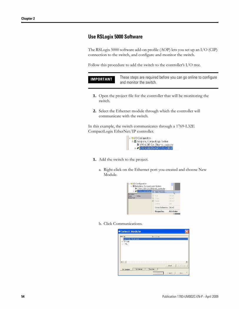
Use RSLogix 5000 Software
The RSLogix 5000 software add-on profile (AOP) lets you set up an I/O (CIP) connection to the switch, and configure and monitor the switch.
Follow this procedure to add the switch to the controller’s I/O tree.
1. Open the project file for the controller that will be monitoring the switch.
2. Select the Ethernet module through which the controller will communicate with the switch.
In this example, the switch communicates through a 1769-L32E CompactLogix EtherNet/IP controller.
1. Add the switch to the project.
a. Right-click on the Ethernet port you created and choose New Module.
b. Click Communications.
IMPORTANT These steps are required before you can go online to configure and monitor the switch.
54 Publication 1783-UM002C-EN-P - April 2009
Chapter 2
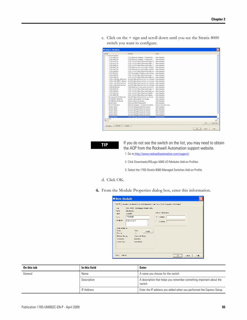
c. Click on the + sign and scroll down until you see the Stratix 8000 switch you want to configure.
d. Click OK.
4. From the Module Properties dialog box, enter this information.
TIP If you do not see the switch on the list, you may need to obtain the AOP from the Rockwell Automation support website.
1. Go to http://www.rockwellautomation.com/support/.
2. Click Downloads/RSLogix 5000 I/O Modules Add-on Profiles.
3. Select the 1783-Stratix 8000 Managed Switches Add-on Profile.
On this tab In this field Enter
General Name A name you choose for the switch
Description A description that helps you remember something important about the switch
IP Address Enter the IP address you added when you performed the Express Setup.
Publication 1783-UM002C-EN-P - April 2009 55
Chapter 2
1. Click OK.
The switch is added to the project.
2. Go online with the switch by choosing Communications online.
You can now configure and monitor the switch using the switch AOP.
For more information on using the switch AOP, refer to the Stratix 8000 Managed Ethernet Switch Software User manual, publication
1783-UM003.
Download Cisco Network Assistant
Cisco Network Assistant is a software tool that you download from Cisco.com and run on your personal computer. It offers advanced options for configuring and monitoring multiple devices, including switches, switch clusters, switch stacks, routers, and access points.
Follow these steps to use the software.
1. Go to http://www.cisco.com/go/NetworkAssistant.
You must be a registered Cisco.com user, but you need no other access privileges.
2. Find the Network Assistant installer.
3. Download the Network Assistant installer, and run it.
You can run it directly from the Web if your browser offers this choice.
4. When you run the installer, follow the displayed instructions.
5. In the final panel, click Finish to complete the Network Assistant installation.
See the Network Assistant online help for more information.
56 Publication 1783-UM002C-EN-P - April 2009
Chapter 2
Use the Command-Line Interface
You can manage the switch from the command-line interface (CLI) by connecting your personal computer directly to the switch console port or through the network by using Telnet. This procedure explains how to access the CLI through the console port.
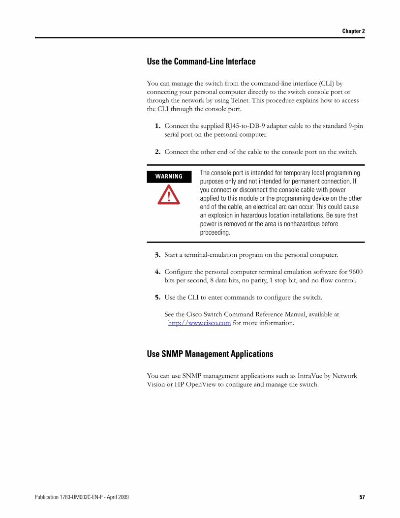
1. Connect the supplied RJ45-to-DB-9 adapter cable to the standard 9-pin serial port on the personal computer.
2. Connect the other end of the cable to the console port on the switch.
3. Start a terminal-emulation program on the personal computer.
4. Configure the personal computer terminal emulation software for 9600 bits per second, 8 data bits, no parity, 1 stop bit, and no flow control.
5. Use the CLI to enter commands to configure the switch.
See the Cisco Switch Command Reference Manual, available at http://www.cisco.com for more information.
Use SNMP Management Applications
You can use SNMP management applications such as IntraVue by Network Vision or HP OpenView to configure and manage the switch.
WARNING The console port is intended for temporary local programming purposes only and not intended for permanent connection. If you connect or disconnect the console cable with power applied to this module or the programming device on the other end of the cable, an electrical arc can occur. This could cause an explosion in hazardous location installations. Be sure that power is removed or the area is nonhazardous before proceeding.
Publication 1783-UM002C-EN-P - April 2009 57

Chapter 2
Reset the Switch to Factory Defaults
Follow this procedure if you need to restore the switch to its factory default settings.
1. Remove power from the switch.
2. Reapply power to the switch.
3. While the switch is powering up, press and hold the Express Setup button.
4. When the EIP Mod, EIP Net and Setup status indictors turn red, release the Express Setup button.
The switch continues powering up in its factory default state.
5. Follow the Set Up the Switch Initially with Express Setup procedure on page 48 to reconfigure the switch.
Connect to the Switch Ports This section describes how to connect to these ports.
• 10/100 copper ports• dual-purpose uplink (10/100/1000 and SFP fiber) ports• 100BaseFX fiber ports
For simplified cabling, the automatic medium-dependent interface crossover (auto-MDIX) feature is enabled by default on the switch. With auto-MDIX enabled, the switch detects the required cable type for copper Ethernet connections and configures the interfaces accordingly. Therefore, you can use either a crossover or a straight-through cable for connections to a switch 10/100 or 10/100/1000 Ethernet port, regardless of the type of device on the other end of the connection.
TIP This procedure resets the switch to its original factory settings. Any configuration changes you may have made will be lost.
58 Publication 1783-UM002C-EN-P - April 2009
Chapter 2
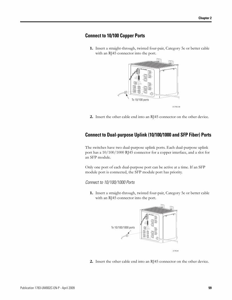
Connect to 10/100 Copper Ports
1. Insert a straight-through, twisted four-pair, Category 5e or better cable with an RJ45 connector into the port.
2. Insert the other cable end into an RJ45 connector on the other device.
Connect to Dual-purpose Uplink (10/100/1000 and SFP Fiber) Ports
The switches have two dual-purpose uplink ports. Each dual-purpose uplink port has a 10/100/1000 RJ45 connector for a copper interface, and a slot for an SFP module.
Only one port of each dual-purpose port can be active at a time. If an SFP module port is connected, the SFP module port has priority.
Connect to 10/100/1000 Ports
1. Insert a straight-through, twisted four-pair, Category 5e or better cable with an RJ45 connector into the port.
2. Insert the other cable end into an RJ45 connector on the other device.
VRT
AA
31795-M
To 10/100 ports
VR
TA
A
31795-M
To 10/100/1000 ports
Publication 1783-UM002C-EN-P - April 2009 59
Chapter 2
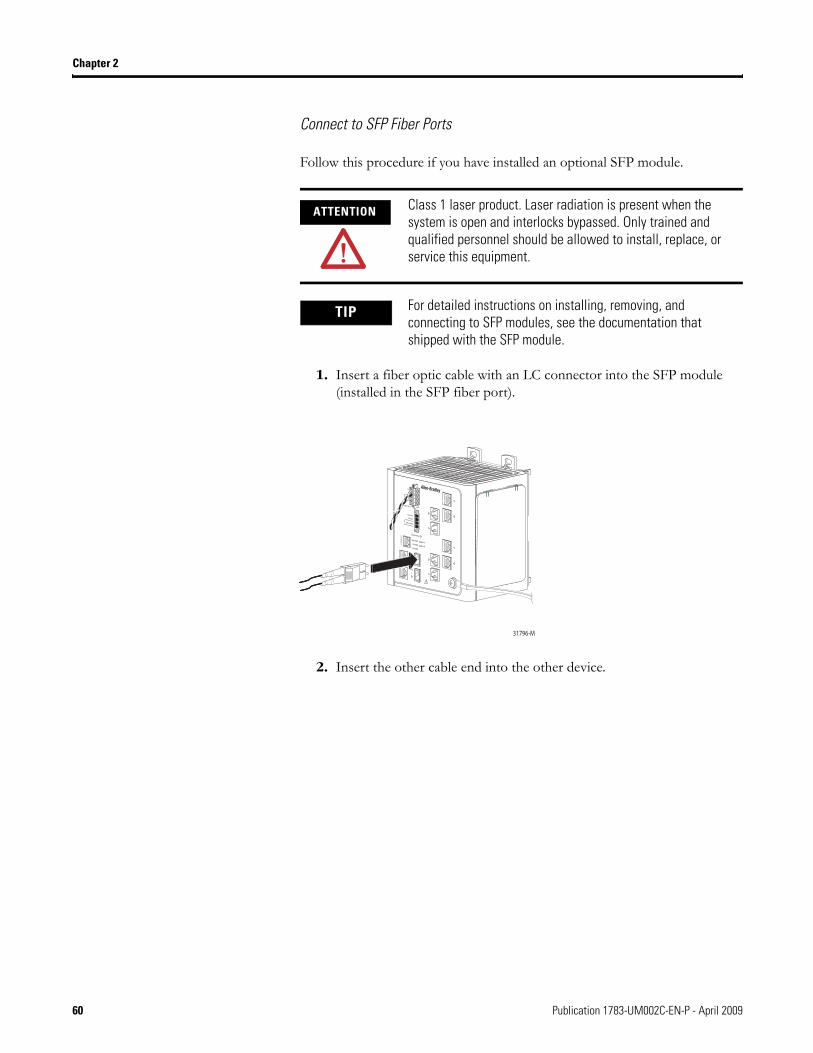
Connect to SFP Fiber Ports
Follow this procedure if you have installed an optional SFP module.
1. Insert a fiber optic cable with an LC connector into the SFP module (installed in the SFP fiber port).
2. Insert the other cable end into the other device.
ATTENTION Class 1 laser product. Laser radiation is present when the system is open and interlocks bypassed. Only trained and qualified personnel should be allowed to install, replace, or service this equipment.
TIP For detailed instructions on installing, removing, and connecting to SFP modules, see the documentation that shipped with the SFP module.
VR
TA
A
31796-M
60 Publication 1783-UM002C-EN-P - April 2009
Chapter 2
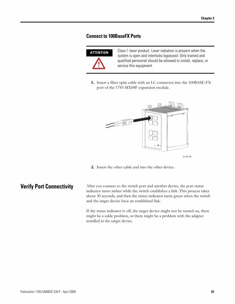
Connect to 100BaseFX Ports
1. Insert a fiber optic cable with an LC connector into the 100BASE-FX port of the 1783-MX08F expansion module.
2. Insert the other cable end into the other device.
Verify Port Connectivity After you connect to the switch port and another device, the port status indicator turns amber while the switch establishes a link. This process takes about 30 seconds, and then the status indicator turns green when the switch and the target device have an established link.
If the status indicator is off, the target device might not be turned on, there might be a cable problem, or there might be a problem with the adapter installed in the target device.
ATTENTION Class 1 laser product. Laser radiation is present when the system is open and interlocks bypassed. Only trained and qualified personnel should be allowed to install, replace, or service this equipment.
31797-M
Publication 1783-UM002C-EN-P - April 2009 61
Chapter 2
Verify Switch Operation Before installing the switch in its final location, you should power on the switch and verify that the switch passes the power-on self-test (POST). These sections describe the steps required to connect a personal computer or terminal to the switch console port, to power on the switch, and to observe POST results.
• Connect a Computer or a Terminal to the Console Port, page 62• Run a Power-on Self-test (POST), page 63
Connect a Computer or a Terminal to the Console Port
To connect a computer to the console port, use the supplied RJ45-to-DB-9 adapter cable. To connect a terminal to the console port, you need to provide an RJ45-to-DB-25 female DTE adapter. For console-port and adapter-pinout information, see Chapter 4, Cable and Connectors .
The computer or terminal must support VT100 terminal emulation. The terminal-emulation software—frequently a computer application such as HyperTerminal—makes communication between the switch and your computer or terminal possible during the POST.
Follow these steps to connect the computer or terminal to the switch.
1. Make sure that your terminal-emulation software is configured to communicate with the switch using hardware flow control.
2. Configure the communication rate and data format of the personal computer or terminal to match these console-port default characteristics.• 9600 K bps communication rate• 8 data bits• 1 stop bit• no parity
After gaining access to the switch, you can change the port communication rate. See the switch software configuration guide for instructions.
WARNING If you connect or disconnect the console cable with power applied to the switch or any device on the network, an electrical arc can occur. This could cause an explosion in hazardous location installations. Be sure that power is removed or the area is nonhazardous before proceeding.
To verify switch operation, perform POST on the switch in a nonhazardous location before installation.
62 Publication 1783-UM002C-EN-P - April 2009
Chapter 2
Run a Power-on Self-test (POST)
When the switch powers on, it automatically initiates a POST. The POST runs a series of tests that verify that the switch functions properly and assures that it is ready to install.
To test the switch, follow these steps.
1. Apply power to the switch.
2. Verify POST Results, page 63.
3. Disconnect Power, page 64.
Verify POST Results When you apply power the switch, it automatically begins a series of self tests (POST). During a POST, you see the following.
• All status indicators are off for a few seconds.• Each status indicator is tested. One at a time, the EIP Mod, EIP Net,
Setup, Pwr A, and Pwr B status indicators each briefly display green, then red, and then go off.
• The EIP Mod status indicator then blinks green as the boot loader verifies the basic functionality of the processing and memory hardware.
• Assuming all tests pass, the EIP Mod status indicator blinks green as the software image loads.
• If the POST fails, the EIP Mod status indicator turns red.
ATTENTION POST failures are usually fatal. Contact your Rockwell Automation representative immediately if your switch does not pass POST.
Publication 1783-UM002C-EN-P - April 2009 63
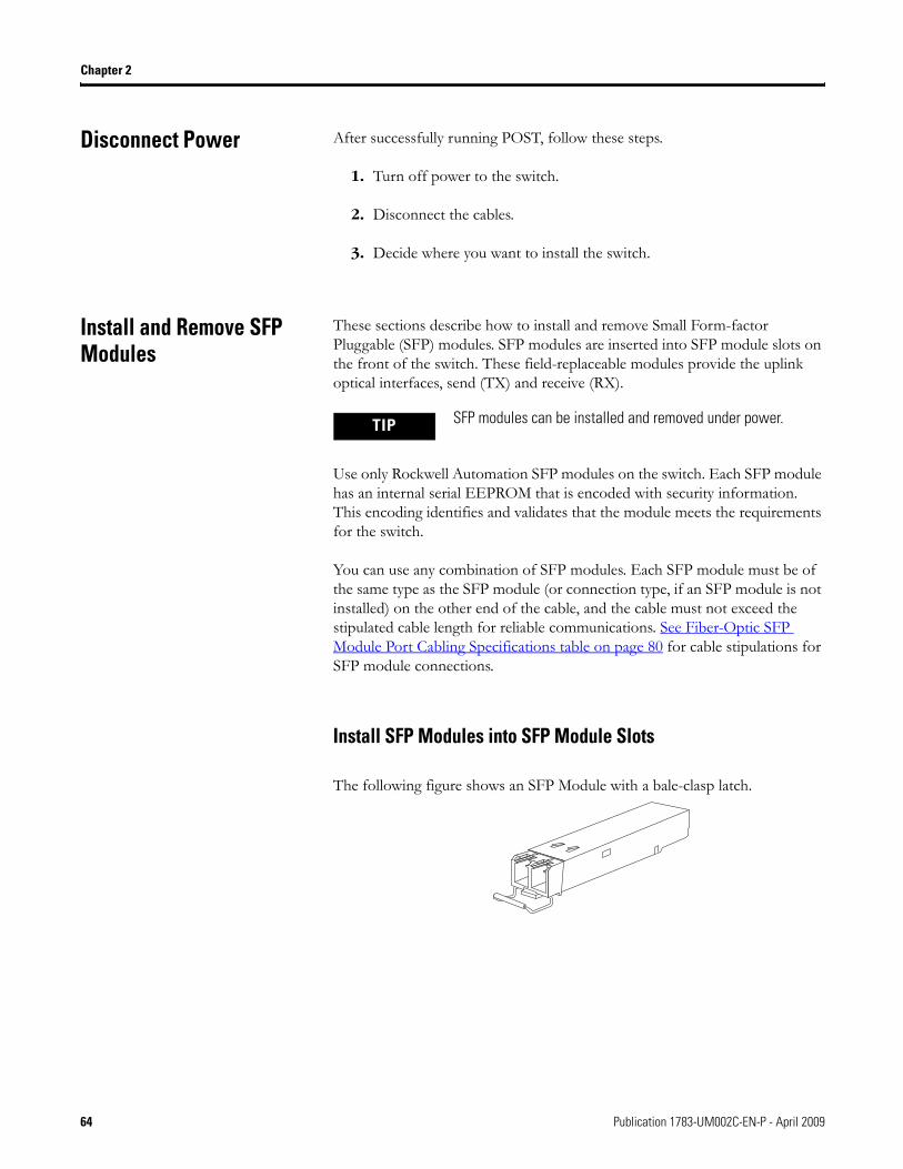
Chapter 2
Disconnect Power After successfully running POST, follow these steps.
1. Turn off power to the switch.
2. Disconnect the cables.
3. Decide where you want to install the switch.
Install and Remove SFP Modules
These sections describe how to install and remove Small Form-factor Pluggable (SFP) modules. SFP modules are inserted into SFP module slots on the front of the switch. These field-replaceable modules provide the uplink optical interfaces, send (TX) and receive (RX).
Use only Rockwell Automation SFP modules on the switch. Each SFP module has an internal serial EEPROM that is encoded with security information. This encoding identifies and validates that the module meets the requirements for the switch.
You can use any combination of SFP modules. Each SFP module must be of the same type as the SFP module (or connection type, if an SFP module is not installed) on the other end of the cable, and the cable must not exceed the stipulated cable length for reliable communications. See Fiber-Optic SFP Module Port Cabling Specifications table on page 80 for cable stipulations for SFP module connections.
Install SFP Modules into SFP Module Slots
The following figure shows an SFP Module with a bale-clasp latch.
TIP SFP modules can be installed and removed under power.
64 Publication 1783-UM002C-EN-P - April 2009
Chapter 2
To insert an SFP module into the SFP module slot, follow these steps:
1. Attach an electrostatic discharge (ESD) preventive wrist strap to your wrist and to a bare metal surface on the chassis.
2. Find the send (TX) and receive (RX) markings that identify the correct side of the SFP module.
On some SFP modules, the send and receive (TX and RX) markings might be replaced by arrows that show the direction of the connection, either send or receive (TX or RX).
3. Grasp the module on the sides and align it in front of the slot opening.
4. Insert the SFP module into the slot until you feel the connector on the module snap into place in the rear of the slot.
5. Remove the dust plugs from the SFP module optical ports and store them for later use.
6. Insert the LC cable connector into the SFP module.
Remove SFP Modules from SFP Module Slots
To remove an SFP module from a module receptacle, follow these steps:
1. Attach an ESD-preventive wrist strap to your wrist and to a bare metal surface on the chassis.
2. Disconnect the LC from the SFP module.
3. Insert a dust plug into the optical ports of the SFP module to keep the optical interfaces clean.
IMPORTANT Do not remove the dust plugs from the SFP module port or the rubber caps from the fiber-optic cable until you are ready to connect the cable. The plugs and caps protect the SFP module ports and cables from contamination and ambient light.
Publication 1783-UM002C-EN-P - April 2009 65
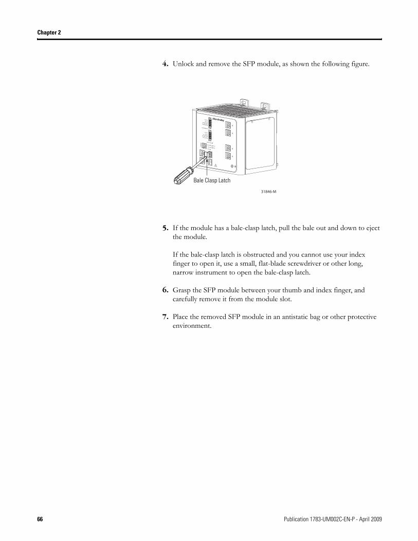
Chapter 2
4. Unlock and remove the SFP module, as shown the following figure.
5. If the module has a bale-clasp latch, pull the bale out and down to eject the module.
If the bale-clasp latch is obstructed and you cannot use your index finger to open it, use a small, flat-blade screwdriver or other long, narrow instrument to open the bale-clasp latch.
6. Grasp the SFP module between your thumb and index finger, and carefully remove it from the module slot.
7. Place the removed SFP module in an antistatic bag or other protective environment.
Bale Clasp Latch
66 Publication 1783-UM002C-EN-P - April 2009
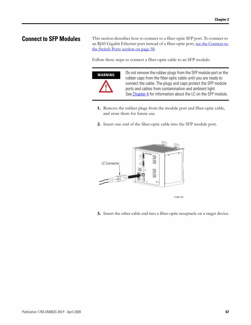
Chapter 2
Connect to SFP Modules This section describes how to connect to a fiber-optic SFP port. To connect to an RJ45 Gigabit Ethernet port instead of a fiber-optic port, see the Connect to the Switch Ports section on page 58.
Follow these steps to connect a fiber-optic cable to an SFP module:
1. Remove the rubber plugs from the module port and fiber-optic cable, and store them for future use.
2. Insert one end of the fiber-optic cable into the SFP module port.
3. Insert the other cable end into a fiber-optic receptacle on a target device.
WARNING Do not remove the rubber plugs from the SFP module port or the rubber caps from the fiber-optic cable until you are ready to connect the cable. The plugs and caps protect the SFP module ports and cables from contamination and ambient light.See Chapter 4 for information about the LC on the SFP module.
LC Connector
Publication 1783-UM002C-EN-P - April 2009 67
Chapter 2
4. Observe the port status indicator.
• The status indicator turns green when the switch and the target device have an established link.
• The status indicator turns amber while the SFP module discovers the network topology and searches for loops. This process takes about 30 seconds, then the port status indicator turns green.
• If the status indicator is off, the target device might not be turned on, there might be a cable problem, or there might be problem with the adapter installed in the target device. See Chapter 3, Troubleshoot the Switch for solutions to cabling problems.
5. If necessary, restart the switch or the target device.
68 Publication 1783-UM002C-EN-P - April 2009
Chapter 3
Troubleshoot the Switch
This chapter provides these topics for troubleshooting the switch.
Obtain Troubleshooting Information
The status indicators on the front panel provide troubleshooting information about the switch. They show power-on self-test (POST) failures, port-connectivity problems, and overall switch performance. You can also get statistics from the browser interface, the command-line interface (CLI), or a Simple Network Management Protocol (SNMP) workstation.
Verify Switch POST Results As power is applied to the switch, it begins the POST, a series of tests that runs automatically to ensure that the switch functions properly. It might take several minutes for the switch to complete POST.
POST starts with status indicator tests that cycle once through the EIP Mod, EIP Net, Setup, Pwr A, and Pwr B status indicators. While POST proceeds, the EIP Mod status indicator blinks green, and all the other status indicators remain off.
If POST completes successfully, the System status indicator changes to solid green, and the other status indicators display their normal operating status. If the switch fails POST, the System status indicator turns red.
Topic Page
Obtain Troubleshooting Information 69
Verify Switch POST Results 69
Verify Switch Status Indicators 70
Verify Switch Connections 70
Verify Switch Performance 73
Obtain Configuration Information 74
ATTENTION POST failures are usually fatal. Contact your Rockwell Automation technical support representative if your switch does not pass POST.
69Publication 1783-UM002C-EN-P - April 2009 69
Chapter 3
View POST Results With a Terminal
If you have a terminal connected to the console port, you can also view POST status and test results on the terminal.
If the terminal displays garbled characters, you might need to reset the terminal-emulation software to 9600 bits per second. Refer to Verify POST Results on page 63 for more information about viewing results on a terminal.
Verify Switch Status Indicators
If you have physical access to the switch, look at the port status indicators for information about the switch. See the following sources for a description of the status indicators colors and their meanings:
• The Status Indicators section on page 15 of this manual• Stratix 8000 Ethernet Managed Switches Installation Instructions,
publication 1783-IN005
Verify Switch Connections Review this section when troubleshooting switch connection problems.
Bad or Damaged Cable
Always make sure that the cable does not have marginal damage or failure. A cable might be just good enough to connect at the physical layer, but it could corrupt packets as a result of subtle damage to the wiring or connectors.
70 Publication 1783-UM002C-EN-P - April 2009
Chapter 3
This situation is likely when the port has many packet errors or the port constantly loses and regains the link. You should:
• Swap the copper or fiber-optic cable with a known, good cable.• Look for broken, bent, or missing pins on cable connectors.• Rule out any bad patch panel connections or media convertors between
the source and destination.
If possible, bypass the patch panel, or eliminate faulty media convertors (fiber-optic-to-copper).
• Try the cable in another port or interface, if possible, to see if the problem follows the cable.
Ethernet and Fiber Cables
Make sure that you have the correct cable type for the connection.
• Use Category 3 copper cable for 10 Mb/s UTP connections. • Category 5, 5e, or 6 UTP or STP cable may be used for 10/100 Mbps
connections. • For 1000 Mbps (1 gigabit per second) connections, use either Category
5e or Category 6 UTP or STP cable. • For fiber-optic connectors, verify that you have the correct cable for the
distance and the port type.• Make sure that the connected device ports both match and use the same
type encoding, optical frequency, and fiber type.
Publication 1783-UM002C-EN-P - April 2009 71
Chapter 3
Link Status
Verify that both sides have a network link. A single broken wire or one shut down port can cause one side to show a link, but not the other side.
A Link status indicator does not guarantee that the cable is fully functional. The cable might have encountered physical stress that causes it to function at a marginal level.
If the Link status indicator for the port is not lit, do the following.
• Connect the cable from the switch to a known good device.• Make sure that both ends of the cable are connected to the correct
ports.• Verify that both devices have power.• Verify that you are using the correct cable type.• Rule out loose connections. Sometimes a cable appears to be seated, but
is not. Disconnect the cable, and then reconnect it.
Transceiver Issues
Use only Rockwell Automation SFP modules on the switch. Each SFP module has an internal serial EEPROM that is encoded with security information. This encoding identifies and validates that the module meets the requirements for the switch. Other manufacturers’ SFP modules will not function correctly.
Check these items.
• Bad or incorrect SFP module.
Exchange the suspect module with a known good module. Verify that the module is supported on this platform.
• Use the CLI show interfaces command or the CLI show int status command to verify the port or module error-disabled or shutdown status. Re-enable the port if needed.
• Make sure that all fiber connections are properly cleaned and securely connected.
72 Publication 1783-UM002C-EN-P - April 2009
Chapter 3
Port and Interface Settings
A cause of port connectivity failure can be a disabled port. Verify that the port or interface is not disabled or powered down for some reason. If a port or interface is manually shut down on one side of the link or the other side, the link does not come up until you re-enable the port. Use the CLI show interfaces privileged EXEC command to verify the port or interface error-disabled, disabled, or shutdown status on both sides of the connection. If needed, re-enable the port or the interface.
Verify Switch Performance Review this section when troubleshooting switch performance problems.
Speed, Duplex, and Autonegotiation
If the port statistics show a large amount of alignment errors, frame check sequence (FCS), or late-collisions errors, this might indicate a speed or duplex mismatch.
A common issue with speed and duplex occurs when the duplex settings are mismatched between two switches, between a switch and a router, or between the switch and a workstation or server. This can happen when manually setting the speed and duplex or from autonegotiation issues between the two devices. A mismatch occurs under these circumstances:
• A manually set speed or duplex parameter is different from the manually set speed or duplex parameter on the connected port.
• A port is set to autonegotiate, and the connected port is set to full duplex with no autonegotiation.
To maximize switch performance and ensure a link, follow one of these guidelines when changing the settings for duplex and speed:
• Let both ports autonegotiate both speed and duplex. • Manually set the same speed and duplex parameters for the ports on
both ends of the connection to the same values.• If a remote device does not autonegotiate, configure the duplex settings
on the two ports to the same values.
The speed parameter can adjust itself even if the connected port does not autonegotiate.
Publication 1783-UM002C-EN-P - April 2009 73
Chapter 3
Autonegotiation and Network Interface Cards (NICs)
Problems sometimes occur between the switch and third-party network interface cards (NICs). By default, the switch ports and interfaces are set to autonegotiate. It is common for devices like laptops or other devices to be set to autonegotiate as well, yet sometimes autonegotation issues occur.
To troubleshoot autonegotiation problems, try manually setting both sides of the connection. If this does not solve the problem, there could be a problem with the firmware or software on your NIC. You can resolve this by upgrading the NIC driver to the latest version available from the manufacturer.
Cabling Distance
If the port statistics show excessive FCS, late-collision, or alignment errors, verify that the cable distance from the switch to the connected device meets the recommended guidelines. See Chapter 4, Cable and Connectors for cabling guidelines.
Obtain Configuration Information
If you contact Rockwell Automation Technical Support, you may be asked to provide configuration information for your switch. You can obtain this information from the Device Manager web interface online help.
Follow this procedure to obtain configuration information for your switch.
1. In the Device Manager web interface, click the Help button.
2. In the left pane, click Support.
3. Click the link labeled Show Information Commonly Needed by TAC.
You see a text file showing configuration information.
4. For future reference, you can save the file (.txt, .mht, .htm, or .html formats).
TIP From the Support dialog box, you can also click on a link that takes you directly to Rockwell Automation technical support.
74 Publication 1783-UM002C-EN-P - April 2009
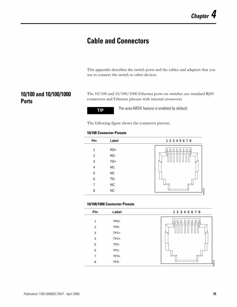
Chapter 4
Cable and Connectors
This appendix describes the switch ports and the cables and adapters that you use to connect the switch to other devices.
10/100 and 10/100/1000 Ports
The 10/100 and 10/100/1000 Ethernet ports on switches use standard RJ45 connectors and Ethernet pinouts with internal crossovers.
The following figure shows the connector pinouts.
10/100 Connector Pinouts
10/100/1000 Connector Pinouts
TIP The auto-MDIX feature is enabled by default.
H5
31
8
2 31 4 5 6 7 8Pin Label
1
2
3
4
5
6
7
8
RD+
RD-
TD+
NC
NC
TD-
NC
NC
6091
52 31 4 5 6 7 8Pin Label
1
2
3
4
5
6
7
8
TP0+
TP0-
TP1+
TP2+
TP2-
TP1-
TP3+
TP3-
75Publication 1783-UM002C-EN-P - April 2009 75
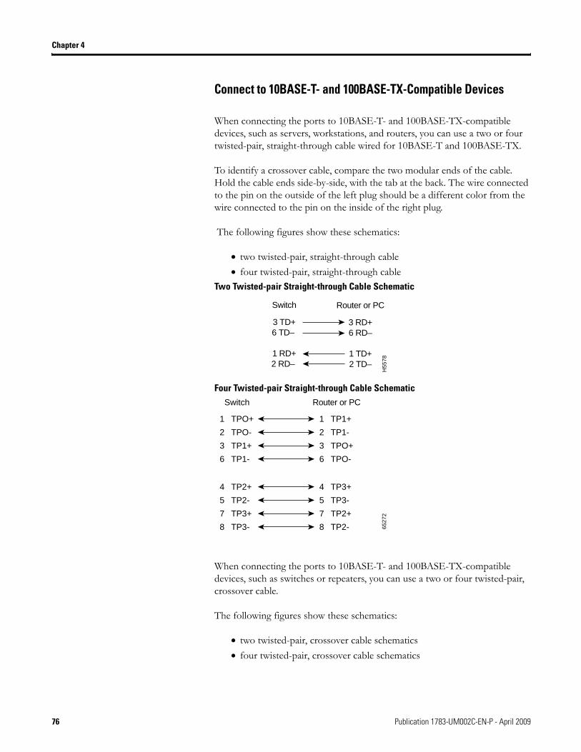
Chapter 4
Connect to 10BASE-T- and 100BASE-TX-Compatible Devices
When connecting the ports to 10BASE-T- and 100BASE-TX-compatible devices, such as servers, workstations, and routers, you can use a two or four twisted-pair, straight-through cable wired for 10BASE-T and 100BASE-TX.
To identify a crossover cable, compare the two modular ends of the cable. Hold the cable ends side-by-side, with the tab at the back. The wire connected to the pin on the outside of the left plug should be a different color from the wire connected to the pin on the inside of the right plug.
The following figures show these schematics:
• two twisted-pair, straight-through cable• four twisted-pair, straight-through cable
Two Twisted-pair Straight-through Cable Schematic
Four Twisted-pair Straight-through Cable Schematic
When connecting the ports to 10BASE-T- and 100BASE-TX-compatible devices, such as switches or repeaters, you can use a two or four twisted-pair, crossover cable.
The following figures show these schematics:
• two twisted-pair, crossover cable schematics• four twisted-pair, crossover cable schematics
Switch
3 TD+6 TD–
1 RD+2 RD–
Router or PC
3 RD+6 RD–
1 TD+2 TD–
H55
78
1 TPO+
2 TPO-
3 TP1+
6 TP1-
1 TP1+
Switch Router or PC
2 TP1-
3 TPO+
6 TPO-
4 TP2+
5 TP2-
7 TP3+
8 TP3-
4 TP3+
5 TP3-
7 TP2+
8 TP2- 6527
2
76 Publication 1783-UM002C-EN-P - April 2009
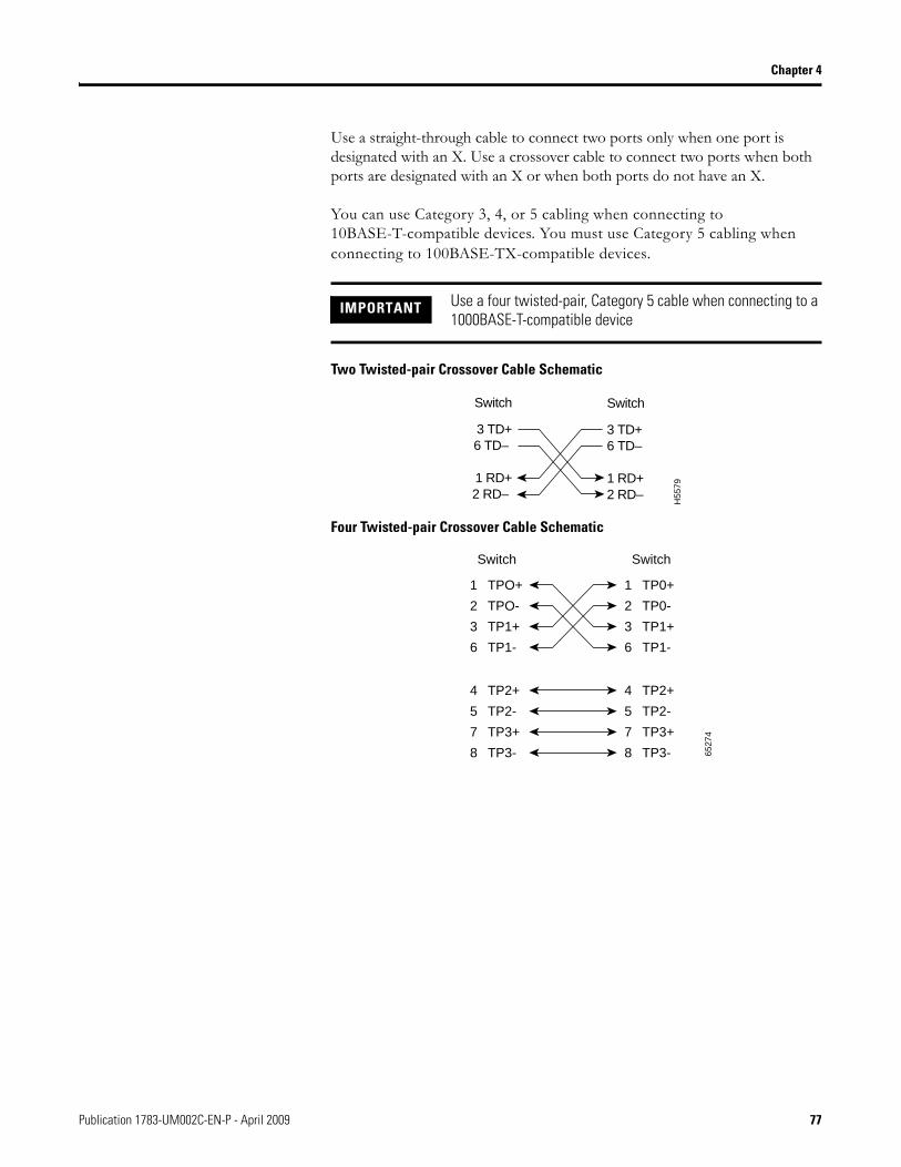
Chapter 4
Use a straight-through cable to connect two ports only when one port is designated with an X. Use a crossover cable to connect two ports when both ports are designated with an X or when both ports do not have an X.
You can use Category 3, 4, or 5 cabling when connecting to 10BASE-T-compatible devices. You must use Category 5 cabling when connecting to 100BASE-TX-compatible devices.
Two Twisted-pair Crossover Cable Schematic
Four Twisted-pair Crossover Cable Schematic
IMPORTANT Use a four twisted-pair, Category 5 cable when connecting to a 1000BASE-T-compatible device
Switch
3 TD+6 TD–
1 RD+2 RD–
Switch
3 TD+6 TD–
1 RD+2 RD–
H55
79
1 TPO+
2 TPO-
3 TP1+
6 TP1-
1 TP0+
Switch Switch
2 TP0-
3 TP1+
6 TP1-
4 TP2+
5 TP2-
7 TP3+
8 TP3-
4 TP2+
5 TP2-
7 TP3+
8 TP3- 6527
4
Publication 1783-UM002C-EN-P - April 2009 77
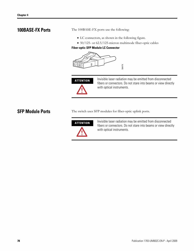
Chapter 4
100BASE-FX Ports The 100BASE-FX ports use the following:
• LC connectors, as shown in the following figure. • 50/125- or 62.5/125-micron multimode fiber-optic cables
Fiber-optic SFP Module LC Connector
SFP Module Ports The switch uses SFP modules for fiber-optic uplink ports.
5847
6
ATTENTION Invisible laser radiation may be emitted from disconnected fibers or connectors. Do not stare into beams or view directly with optical instruments.
ATTENTION Invisible laser radiation may be emitted from disconnected fibers or connectors. Do not stare into beams or view directly with optical instruments.
78 Publication 1783-UM002C-EN-P - April 2009
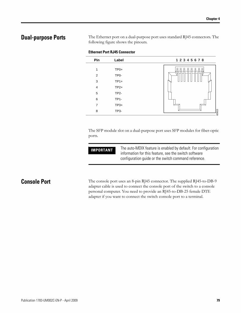
Chapter 4
Dual-purpose Ports The Ethernet port on a dual-purpose port uses standard RJ45 connectors. The following figure shows the pinouts.
Ethernet Port RJ45 Connector
The SFP module slot on a dual-purpose port uses SFP modules for fiber-optic ports.
Console Port The console port uses an 8-pin RJ45 connector. The supplied RJ45-to-DB-9 adapter cable is used to connect the console port of the switch to a console personal computer. You need to provide an RJ45-to-DB-25 female DTE adapter if you want to connect the switch console port to a terminal.
6091
5
2 31 4 5 6 7 8Pin Label
1
2
3
4
5
6
7
8
TP0+
TP0-
TP1+
TP2+
TP2-
TP1-
TP3+
TP3-
IMPORTANT The auto-MDIX feature is enabled by default. For configuration information for this feature, see the switch software configuration guide or the switch command reference.
Publication 1783-UM002C-EN-P - April 2009 79
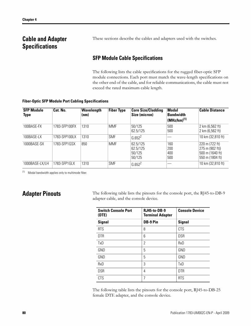
Chapter 4
Cable and Adapter Specifications
These sections describe the cables and adapters used with the switches.
SFP Module Cable Specifications
The following lists the cable specifications for the rugged fiber-optic SFP module connections. Each port must match the wave-length specifications on the other end of the cable, and for reliable communications, the cable must not exceed the rated maximum cable length.
Adapter Pinouts The following table lists the pinouts for the console port, the RJ45-to-DB-9 adapter cable, and the console device.
The following table lists the pinouts for the console port, RJ45-to-DB-25 female DTE adapter, and the console device.
Fiber-Optic SFP Module Port Cabling Specifications
SFP Module Type
Cat. No. Wavelength (nm)
Fiber Type Core Size/Cladding Size (micron)
Modal Bandwidth (MHz/km)(1)
(1) Modal bandwidth applies only to multimode fiber.
Cable Distance
100BASE-FX 1783-SFP100FX 1310 MMF 50/12562.5/125
500500
2 km (6,562 ft) 2 km (6,562 ft)
100BASE-LX 1783-SFP100LX 1310 SMF G.6522 — 10 km (32,810 ft)
1000BASE-SX 1783-SFP1GSX 850 MMF 62.5/12562.5/12550/12550/125
160200400500
220 m (722 ft)275 m (902 ft))500 m (1640 ft)550 m (1804 ft)
1000BASE-LX/LH 1783-SFP1GLX 1310 SMF G.6522 — 10 km (32,810 ft)
Switch Console Port (DTE)
RJ45-to-DB-9Terminal Adapter
Console Device
Signal DB-9 Pin Signal
RTS 8 CTS
DTR 6 DSR
TxD 2 RxD
GND 5 GND
GND 5 GND
RxD 3 TxD
DSR 4 DTR
CTS 7 RTS
80 Publication 1783-UM002C-EN-P - April 2009

Chapter 4
The RJ45-to-DB-25 female DTE adapter is not supplied with the switch.
Switch ConsolePort (DTE)
RJ45-to-DB-25Terminal Adapter
ConsoleDevice
Signal DB-25 Pin Signal
RTS 5 CTS
DTR 6 DSR
TxD 3 RxD
GND 7 GND
GND 7 GND
RxD 2 TxD
DSR 20 DTR
CTS 4 RTS
Publication 1783-UM002C-EN-P - April 2009 81

Chapter 4
Notes:
82 Publication 1783-UM002C-EN-P - April 2009
How Are We Doing?Your comments on our technical publications will help us serve you better in the future.Thank you for taking the time to provide us feedback.
You can complete this form and mail (or fax) it back to us or email us at
[email protected].Please complete the sections below. Where applicable, rank the feature (1=needs improvement, 2=satisfactory, and 3=outstanding).
Pub. Title/Type Stratix 8000 Managed Ethernet Switches Hardware User Manual
Cat. No. 1783-MS06T, 1783-MS10T, 1783-MX08T, 1783-MX08F
Pub. No. 1783-UM002A-EN-E Pub. Date April 2009 Part No.
Overall Usefulness 1 2 3 How can we make this publication more useful for you?
Completeness(all necessary information
is provided)
1 2 3 Can we add more information to help you?
procedure/step illustration feature
example guideline other
explanation definition
Technical Accuracy(all provided information
is correct)
1 2 3 Can we be more accurate?
text illustration
Clarity(all provided information is
easy to understand)
1 2 3 How can we make things clearer?
Other Comments You can add additional comments on the back of this form.
Your Name
Your Title/Function Would you like us to contact you regarding your comments?
Location/Phone ___No, there is no need to contact me
___Yes, please call me
___Yes, please email me at _______________________
___Yes, please contact me via _____________________
Return this form to: Rockwell Automation Technical Communications, 1 Allen-Bradley Dr., Mayfield Hts., OH 44124-9705
Fax: 440-646-3525 Email: [email protected]
Publication CIG-CO521D-EN-P- July 2007

Other Comments
PLEASE FOLD HERE
NO POSTAGE NECESSARY IF MAILED
IN THE UNITED STATES
BUSINESS REPLY MAILFIRST-CLASS MAIL PERMIT NO. 18235 CLEVELAND OH
POSTAGE WILL BE PAID BY THE ADDRESSEE
1 ALLEN-BRADLEY DRMAYFIELD HEIGHTS OH 44124-9705
PLEASE FASTEN HERE (DO NOT STAPLE)
PLEA
SE R
EMOV
E
Index
Numerics10/100 ports
cable lengths 25described 13
10/100/1000 ports 17cable lengths 25described 12, 13
100BASE-FX portscable lengths 25described 13
Aadapter pinouts, terminal
RJ45-to-DB-25 80RJ45-to-DB-9 80
additional resources 6airflow
required clearance 25alarm relay connections
connection procedures 44, 45power and relay connector 11
alarmswiring 44
auto-MDIX 14, 75, 79autonegotiation 13
troubleshooting 73
Ccables
crossoverfour twisted-pair pinout,
1000BASE-T ports 77identifying 76using 76
optical 80SFP module 80straight-through
two twisted-pair pinout 76using 76
cabling10/100 ports 14auto-MDIX 14, 75, 79
clearance 25Compact Flash memory card 19connecting
to computer 62to console port 62to external alarm devices 44, 45to SFP modules 67, 68to terminal 62
connectors and cables10/100/1000 76, 77console 79, 81dual-purpose 79SC connectors 78SFP module ports 78
console portconnecting to 62default characteristics 62described 12specifications 79, 81
crossover cablepinout
four twisted-pair, 1000BASE-T ports 77
Ddefault characteristics of the console
port 62diagnosing problems 69dual-purpose ports 12
connectors and cables 79described 12
duplextroubleshooting 73
Eelectrical noise, avoiding 25environment and enclosure 24ESD
requirements 24Ethernet and fiber cable troubleshooting
71
Ffront panel
10/100 ports 13, ??-14clearance 25console port 12described 8dual-purpose ports 12illustrated 8power and relay connector 11
functional ground lug warning 22
Hhazardous location warnings
console cable 12, 62
Publication 1783-UM002C-EN-P - April 2009 83
Iindustrial environment warning 23installation 29
guidelines 24package contents 26POST 63pre-installation information and
guidelines 25required clearance 25verifying switch operation 62, 64wiring the relays 44, 45
installing SFP modules 64
LLC connector 78link status troubleshooting 72
Nnoise, electrical 25
Ppackage contents 26patch cables, MT-RJ 26pinouts
10/100 ports 78crossover cables
four twisted-pair, 1000BASE-T ports 77
RJ45-to-DB-25 terminal adapter 81RJ45-to-DB-9 terminal adapter 80SFP module 78straight-through cables
two twisted-pair 76port and interface troubleshooting 73ports
10/100/1000 17dual-purpose 12See 10/100 ports, 10/100/1000 ports,
100BASE-FX ports, 100BASE-LX ports, and console ports 13
POSTdescription 63results 63
running at power on 69status indicators 69
powerconnecting to
power and relay connector 11power and relay connector 11
described 11power connection
power and relay connector 11power on 63procedures
power on 63
Rrear panel
clearance 25relays
connecting topower and relay connector 11
described 11wiring 44, 45
removing SFP modules 65, 66RJ45 connector, console port 79
Ssafety warnings 23SC connector 78SFP modules
bale-clasp latch removal 66cables 80connecting to 67, 68connectors 78installation 64
speedtroubleshooting 73
status indicatorsPOST results 69
straight-through cablepinout
two twisted-pair 10/100 ports 76, 77supply wires warning 23switch placement 25switch, power-on 63
84 Publication 1783-UM002C-EN-P - April 2009
Tterminal-emulation software 62troubleshooting
bad or damaged cable 70connection problems 70diagnosing problems 69Ethernet and fiber cables 71link status 72port and interface settings 73POST 69speed, duplex, and autonegotiation 73switch performance 73understanding POST results 69
Vverifying package contents 26verifying switch operation 62, 64
Wwarnings
functional ground lug 22hazardous locations
console cable 12, 62industrial environment 23installation 23supply wires 23
wiring the relays 44, 45
Publication 1783-UM002C-EN-P - April 2009 85

86 Publication 1783-UM002C-EN-P - April 2009


Publication 1783-UM002C-EN-P - April 2009 92 Copyright © 2009 Rockwell Automation, Inc. All rights reserved. Printed in the U.S.A.
Rockwell Automation Support
Rockwell Automation provides technical information on the Web to assist you in using its products. At http://support.rockwellautomation.com, you can find technical manuals, a knowledge base of FAQs, technical and application notes, sample code and links to software service packs, and a MySupport feature that you can customize to make the best use of these tools.
For an additional level of technical phone support for installation, configuration, and troubleshooting, we offer TechConnect support programs. For more information, contact your local distributor or Rockwell Automation representative, or visit http://support.rockwellautomation.com.
Installation Assistance
If you experience a problem within the first 24 hours of installation, please review the information that's contained in this manual. You can also contact a special Customer Support number for initial help in getting your product up and running.
New Product Satisfaction Return
Rockwell Automation tests all of its products to ensure that they are fully operational when shipped from the manufacturing facility. However, if your product is not functioning and needs to be returned, follow these procedures.
United States 1.440.646.3434Monday – Friday, 8am – 5pm EST
Outside United States
Please contact your local Rockwell Automation representative for any technical support issues.
United States Contact your distributor. You must provide a Customer Support case number (call the phone number above to obtain one) to your distributor in order to complete the return process.
Outside United States
Please contact your local Rockwell Automation representative for the return procedure.