Embed Size (px)
Citation preview
Strategies for unmanned lunar rovers: Integration of teleoperation and autonomy based on field testing. M. J. Roman1, M. C. Malin1, M. A. Ravine1, and M. S. Robinson2 , 1Malin Space Science Systems, 5880 Pacific Center
Blvd., San Diego, CA 92121, [email protected], 2Arizona State University, Box 871404, Tempe, AZ. Introduction: The limits on effective rover opera-
tions based on command/response latency need addi-tional exploration. One of the chief operations of scien-tific instrumentation depends on proper placement of the rover to conduct such operations. This placement begins with driving to the site of interest, then ap-proaching the target of interest, and finally deploying the instrumentation.
Our goal is to more clearly define the limits of rov-er interactivity due to latency and identify tasks that can be performed by teleoperations, and those that must be performed autonomously. In order to quickly access targets of interest, we propose the use of a ro-bust rover design and operating strategy that incorpo-rates features from two previous field tests. The result-ant system allows the rover to more efficiently and effectively traverse a risky environment and reduce human error.
Teleoperated Rover (“Copernicus”): In order to demonstrate many key capabilities necessary to con-duct a previously proposed lunar mission, we devel-oped a prototype robotic vehicle (Figure 1) and tested it in terrain representative of the lunar crater, Coperni-cus (95 km diameter). Our rover mobility requirements include: 30 cm/sec forward progress while encounter-ing 30° slopes, and 30 cm obstacles over 30% of a sur-face. We chose these requirements to facilitate the ex-ploration of a significant portion of the floor of Coper-nicus crater during the first lunar day of operations.
Figure 1. The Copernicus Rover during the Amboy field test, traversing a mound of small boulders; (bottom), the Apollo Lunar Roving Vehicle (LRV) at approximately the same scale.
Teleoperated Rover Design: The rover is a 4-wheel drive, 4-wheel steering vehicle supported by a passive suspension system. The two halves of the suspension
are connected to the body (which houses the electron-ics, drive motors and batteries) by a differential mech-anism to improve the stability of the scientific instru-mentation. The roll angle of the body on uneven terrain is reduced by the differential. The differential also al-lows all four wheels to continuously maintain ground contact with a relatively even weight distribution. The 74 cm wheel diameter is very close to the Apollo Lu-nar Rover (LRV) design (Figure 2). A ground clear-ance of 40 cm is achieved through the combination of the large diameter wheels driven from a secondary gearbox with an offset axle.
Figure 2 (top). The Copernicus Rover during the Amboy field test, traversing a mound of small boulders; (bottom) the Apollo Lunar Roving Vehicle (LRV) at approximately the same scale.
Teleoperated Rover Field Testing and Driver Tri-als: The first version of the Copernicus rover was con-ducted at Amboy Crater National Landmark in the Mojave Desert, approximately 130 km east of Barstow, California along the National Historic Highway Route 66 [1]. Five days of driver training through evaluation
courses and an extended longitudinal traverse accumu-lated approximately 14 km over moderately rugged lava flows and smoother alluvial and eolian infill. At one point the traverse covered 3.6 km in less than 7 hours, including waypoint stops representing in-transit science observations. Tests included a closed circuit course for driver training and evaluation of various operating parameters.
The Amboy tests were run using a set of controlled parameters that permitted quantitative demonstration of the operational limits for a realistic lunar mission. Among the factors within the experimental matrix were the effects of image quality (image size and compression factor), frame rate, and time-delay in normal flight operations. Five drivers were evaluated during initial training using 640 X 512 pixel imagery, JPEG quality 75 at 12 frames per second, and no time delay. Training was completed on smooth terrain and then under increasingly more challenging conditions (we assumed a worst worst-case downlink scenario of 34-m DSN performance supporting 320 X 256 pixels, JPEG quality 30, 2 fps with a 4 sec time delay). Ap-proximately one-half of each traverse was conducted with these stringent parameters. With a peak velocity of about 100 cm/s, the vehicle averaged 35 cm/sec during traverses. Much of the low average velocity resulted from the unique test conditions (e.g., sage-brush was difficult to see in degraded images until the vehicle was nearly upon the plant, leading to a stop-and-go velocity cadence on vegetated portions of the course that was not representative of unvegetated are-as). After accounting for these effects, statistical trends representing the effects of time delay, frame rate, and image quality on both learning (driver effectiveness on an unfamiliar terrain) and traversing (effectiveness on a familiar terrain) were readily visible in the test data. For a variety of terrain types, time delay increased traverse time linearly within the parameter space of realistic time delays (3+ seconds of two-way light-time plus about 1 second of ground system delay). The ef-fect net speed at 4 seconds latency was approximately 50% (relative to no time delay).
The impact of time-delays of 6 or more seconds was estimated from extrapolation of the test data (0 to 4 seconds delay). Image quality affected drive time in a non-linear manner provided image size and compres-sion permitted the drivers to discriminate the requisite cues; drivers were more efficient at higher frame rate and lower image quality than at higher image quality and lower frame rate. We attribute this preference for higher frame rates (lower quality) to the ability of the human eye-brain system to fill in detail from motion and stereoscopic images, as long as the latency is rela-tively low (<4 s).
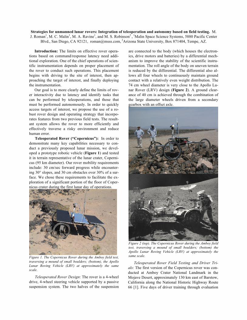
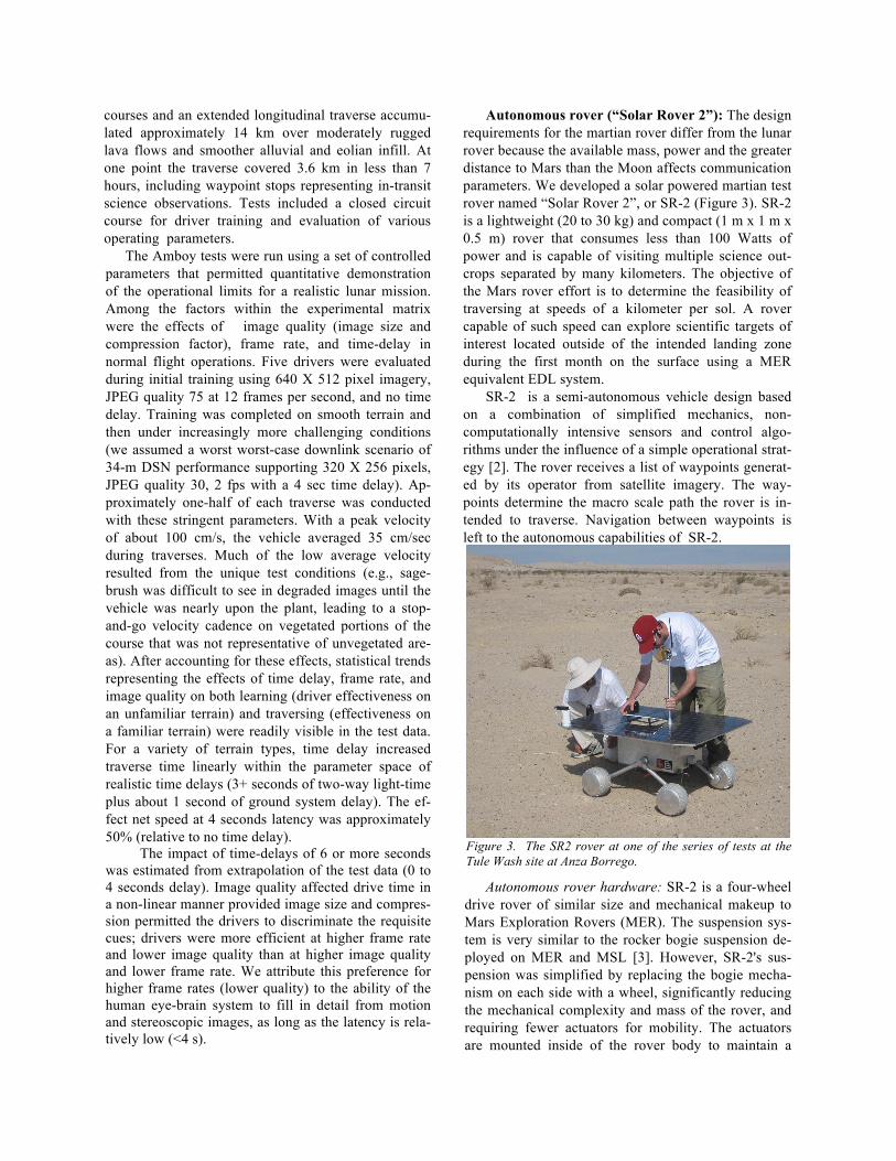
Autonomous rover (“Solar Rover 2”): The design requirements for the martian rover differ from the lunar rover because the available mass, power and the greater distance to Mars than the Moon affects communication parameters. We developed a solar powered martian test rover named “Solar Rover 2”, or SR-2 (Figure 3). SR-2 is a lightweight (20 to 30 kg) and compact (1 m x 1 m x 0.5 m) rover that consumes less than 100 Watts of power and is capable of visiting multiple science out-crops separated by many kilometers. The objective of the Mars rover effort is to determine the feasibility of traversing at speeds of a kilometer per sol. A rover capable of such speed can explore scientific targets of interest located outside of the intended landing zone during the first month on the surface using a MER equivalent EDL system.
SR-2 is a semi-autonomous vehicle design based on a combination of simplified mechanics, non-computationally intensive sensors and control algo-rithms under the influence of a simple operational strat-egy [2]. The rover receives a list of waypoints generat-ed by its operator from satellite imagery. The way-points determine the macro scale path the rover is in-tended to traverse. Navigation between waypoints is left to the autonomous capabilities of SR-2.
Figure 3. The SR2 rover at one of the series of tests at the Tule Wash site at Anza Borrego.
Autonomous rover hardware: SR-2 is a four-wheel drive rover of similar size and mechanical makeup to Mars Exploration Rovers (MER). The suspension sys-tem is very similar to the rocker bogie suspension de-ployed on MER and MSL [3]. However, SR-2's sus-pension was simplified by replacing the bogie mecha-nism on each side with a wheel, significantly reducing the mechanical complexity and mass of the rover, and requiring fewer actuators for mobility. The actuators are mounted inside of the rover body to maintain a
nominal temperature for proper lubrication leading to longer actuator life. All four wheels maintain ground contact with equal force by use of a differential mecha-nism. SR-2 has a ground clearance greater than a wheel diameter (20cm) with minimal protruding suspension structure to reduce hang-ups on rough terrain. Steering is accomplished by changing the speed of the left and right pairs of wheels, known as skid or differential steering.
Navigation: A pair of scanning laser range finders makes up the primary obstacle detection system. One laser scans for obstacles higher than the ground clear-ance of the rover to avoid high centering on the body of the rover. The other laser scans downward just in front of the rover to detect holes or obstacles below the ground plane. Angles of roll and pitch are measured from an onboard accelerometer.
Rover localization is accomplished through dead reckoning. Each drive motor has associated electronics for measuring rotational speed and position. SR-2 scales the motor position by the drive train gear reduc-tion and wheel diameter to determine distance traveled. Position errors caused by wheel slippage were less than 2%, and usually less than 1% of the distance traveled.
Autonomous Field Testing: The Anza Borrego de-sert was selected as a field-test site because of its simi-lar geologic features to more easily accessible layered or sedimentary materials on Mars [4]. The fieldwork was completed in 17 days where SR-2 traversed over 13.7 km. Almost half of the days the rover accom-plished autonomous drives greater than 900 m.
Conclusions: The original requirements we placed on each of our rover systems for their particular plane-tary environments were met with a simple, robust robot design.
Teleoperation: We found that with plausible Earth-to-lunar surface link performance, human teleopera-tions are at least ten times more effective than autono-mous operations, both in terms of distances achieved, speeds at which those distances are achieved, and the recognition of, and access to scientifically interesting targets. We also found that operators can be trained quickly and efficiently.
Autonomy: The simplified mobility system of SR-2 is quite capable of autonomously traversing Mars-like terrain while being very power efficient in most cases. More power is required when the rover changes direc-tion compared to Rocky style rovers. However, only a small portion of the traverse is spent turning, even on complex terrain. As a result of the simpler mobility and despite the comparatively large amount of power used on SR-2 for the computation and communication (when compared to similar class vehicles such as So-journer) it has a much larger range per sol [5].
Integration: To maximize cost-effectiveness of sur-face roving on the Moon, an integration of these two complementary approaches to obstacle negotiation offers substantial promise. Human-in-the-loop opera-tion allows progress to be made through terrains chal-lenging to the simple autonomous algorithm. The sim-ple, autonomous obstacle negotiation allows progress to be made across less challenging surface without a human operator (reducing staffing requirements).
Future effort: Traverses of a kilometer or more per day are possible with a single communication cycle, rather than the 10 to 100 meter/sol currently being ac-complished on Mars. MER and MSL have mechanical-ly limited drive mechanisms and cannot achieve such a high travers rate. However, the operational strategy for these rovers does not allow them to traverse farther than can be seen from images taken the previous day which limits their daily driving distance.
Future robotic missions can accomplish more by relying on the autonomous capabilities of the rover. We believe that the operational philosophy of provid-ing numerous, widely spaced waypoints per communi-cation cycle was largely responsible for the significant distances traveled per day. This difference in opera-tions is more significant for improved performance than the hardware and software differences between SR-2 and MER/MSL.
Having demonstrated both styles of obstacle nego-tiation in realistic field conditions, the next step will be to integrate both into a single test rover. This upgraded version of Copernicus will provide a testbed both for further exploration of the impact of latency and resolu-tion of human-in-the-loop operation and for evaluation of integrated human/autonomous mobility strategies in real-world field conditions.
References: [1] Malin, M. C., M. A. Ravine, M. S. Robinson, M. Roman, and D. Miller (2012), Int’l Workshop on Instrumentation for Planetary Missions, Abstract #1115. [2] Matthew J. Roman. Design and analysis of a four-wheeled planetary rover. Master’s thesis, University of Oklahoma, August 2005. [3] D. Bickler. The new family of jpl planetary surface vehi-cles. In D. Moura, editor, Missions, Technologies and Design of Planetary Mobile Vehicles, Toulouse France, 1993. Cepadues-Editions Publisher. IAF-97 - Q.2.07 1997. [4] M. C. Malin and K. S. Edgett. Mars global surveyor mars orbiter camera: Interplanetary cruise through primary mission. J. Geophys. Res., 106 (E10):2342923570, 2001. [5] David P. Miller, Timo-thy S. Hunt, and Matthew J. Roman. Experiments & analysis of the role of solar power in limiting mars rover range. In Proceedings of the IROS 2003 Confer-ence, October 2003.