Embed Size (px)
DESCRIPTION
Cross Laminated TimberFire protection
Citation preview
www.clt.info
www.storaenso.com
CLT - Cross Laminated Timber
Fire protection
�������������A��B�CDE�������������A��B�CDE�������������A��B�CDE�������������A��B�CDE���� ����
Page 1 of 50
C O N T E N T S
Version 01/2014 AG
It should be noted that this fact sheet on fire protection is merely intended to support the user. Stora Enso Wood Products does not assume any responsibility for the accuracy or completeness of this document.
1 Introduction ..................................................................................................................................................... 3
1.1 Fire protection ........................................................................................................................................... 3
1.2 The building material, wood when exposed to fire ................................................................................... 3
2 Reaction-to-fire performance of building products ..................................................................................... 5
3 Fire resistance of building components ...................................................................................................... 6
3.1 Classification ............................................................................................................................................. 6
3.2 Fire protective cladding ............................................................................................................................. 7
3.3 Fire resistance of CLT components .......................................................................................................... 7
4 Verification of the fire resistance of CLT elements based on classification reports according to EN 13501-2 ....................................................................................................................................................... 8
4.1 CLT external wall structures ..................................................................................................................... 8
4.2 CLT wall structures ................................................................................................................................... 9
4.3 CLT ceiling structures ............................................................................................................................... 10
5 Verification of the fire resistance of CLT elements based on calculations according to EN 1995-1-2:2011 (Eurocode 5) ....................................................................................................................................... 11
5.1 Verification method for actions in the fire situation according to EN 1995-1-2:2011 ................................ 11
5.2 Verification method for mechanical resistance in the fire situation according to EN 1995-1-2:2011 ....... 13
5.3 Charring rates for Stora Enso CLT ........................................................................................................... 14
5.3.1 Design value of charring rates �0 for CLT on surfaces which are unprotected throughout the duration of the fire .............................................................................................................................................. 14
5.3.2 Design value of charring rates �0 for CLT on surfaces which are initially protected from exposure to fire by gypsum plasterboard ................................................................................................................ 16
�������������A��B�CDE�������������A��B�CDE�������������A��B�CDE�������������A��B�CDE���� ����
Page 2 of 50
C O N T E N T S
5.4 Determining the load-bearing capacity (R) of CLT elements according to EN 1995-1-2:2011 ................ 22
5.5 Determining the integrity (E) and insulation (I) of CLT elements .............................................................. 24
5.5.1 The insulating and protective layers of a component .......................................................................... 25
5.5.2 Determining a layer’s basic times ........................................................................................................ 28
5.5.3 Calculating the position coefficient kpos ................................................................................................ 29
5.5.4 Determining the joint coefficient kj,i ...................................................................................................... 32
5.5.5 Calculation model/application for CLT ................................................................................................. 32
6 Technical fire protection of detailing ........................................................................................................... 33
6.1 Joints and connections between components .......................................................................................... 33
6.2 Installations and fixtures ........................................................................................................................... 34
6.3 Fire-retarding sealing in CLT constructions .............................................................................................. 34
6.4 Fasteners .................................................................................................................................................. 35
6.5 Double-layered components ..................................................................................................................... 35
7 Bibliography .................................................................................................................................................... 36
Annex 1 – Design examples ............................................................................................................................... 40
A 1.1 Determining the charring rate of Stora Enso CLT (non-faced) .............................................................. 40
A 1.2 Determining the charring rate of Stora Enso CLT (faced) ...................................................................... 41
A 1.3 Determining the notional charring depth of Stora Enso CLT (non-faced) .............................................. 42
A 1.4 Determining the integrity (EI) of Stora Enso CLT (faced) ...................................................................... 43
Annex 2 – Information on the residual cross-section and integrity of Stora Enso CLT components ........ 46
A 2.1 Calculated residual cross-section and integrity of CLT wall structures (non-faced) .............................. 47
A 2.2 Calculated residual cross-section and integrity of CLT wall structures with single layered fire protection plasterboard cladding (12.5 mm) on the fire-exposed side of the component ....................................... 48
A 2.3 Calculated residual cross-section and integrity of CLT wall structures with service cavity (50 mm, rock fibre) and single layered fire protection plasterboard cladding (12.5 mm) on the fire-exposed side of the component .............................................................................................................................................. 49
A 2.4 Calculated residual cross-section and integrity of CLT ceiling structures (non-faced) ........................... 50
�������������A��B�CDE�������������A��B�CDE�������������A��B�CDE�������������A��B�CDE���� ����
Page 3 of 50
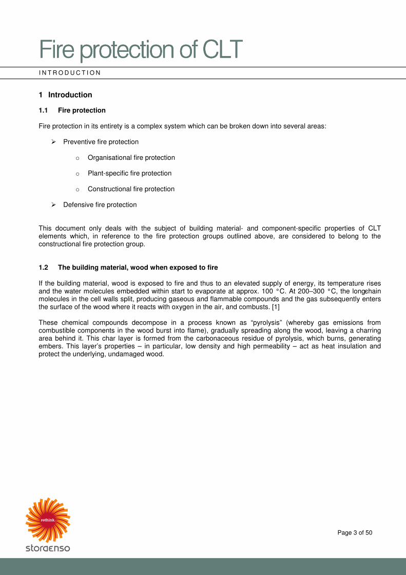
I N T R O D U C T I O N 1 Introduction
1.1 Fire protection Fire protection in its entirety is a complex system which can be broken down into several areas:
� Preventive fire protection
o Organisational fire protection
o Plant-specific fire protection
o Constructional fire protection
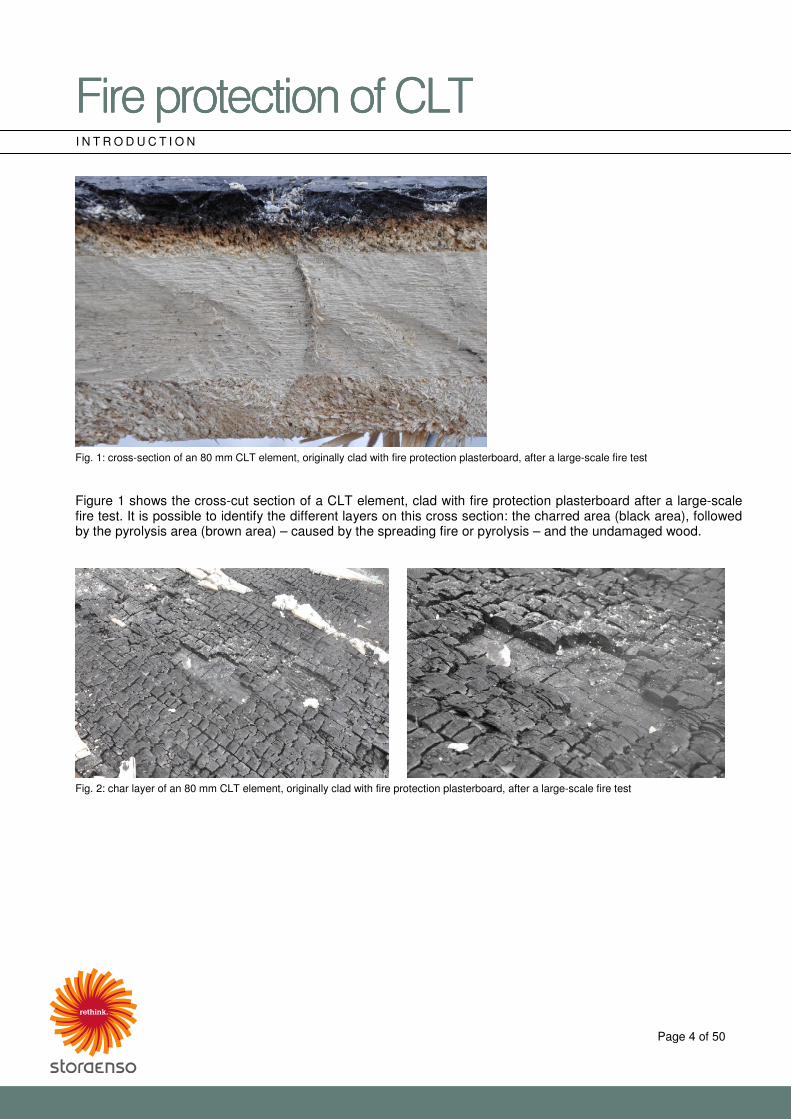
� Defensive fire protection This document only deals with the subject of building material- and component-specific properties of CLT elements which, in reference to the fire protection groups outlined above, are considered to belong to the constructional fire protection group. 1.2 The building material, wood when exposed to fire If the building material, wood is exposed to fire and thus to an elevated supply of energy, its temperature rises and the water molecules embedded within start to evaporate at approx. 100 °C. At 200–300 °C, the long-chain molecules in the cell walls split, producing gaseous and flammable compounds and the gas subsequently enters the surface of the wood where it reacts with oxygen in the air, and combusts. [1] These chemical compounds decompose in a process known as “pyrolysis” (whereby gas emissions from combustible components in the wood burst into flame), gradually spreading along the wood, leaving a charring area behind it. This char layer is formed from the carbonaceous residue of pyrolysis, which burns, generating embers. This layer’s properties – in particular, low density and high permeability – act as heat insulation and protect the underlying, undamaged wood.
�������������A��B�CDE�������������A��B�CDE�������������A��B�CDE�������������A��B�CDE���� ����
Page 4 of 50
I N T R O D U C T I O N
Fig. 1: cross-section of an 80 mm CLT element, originally clad with fire protection plasterboard, after a large-scale fire test Figure 1 shows the cross-cut section of a CLT element, clad with fire protection plasterboard after a large-scale fire test. It is possible to identify the different layers on this cross section: the charred area (black area), followed by the pyrolysis area (brown area) – caused by the spreading fire or pyrolysis – and the undamaged wood.
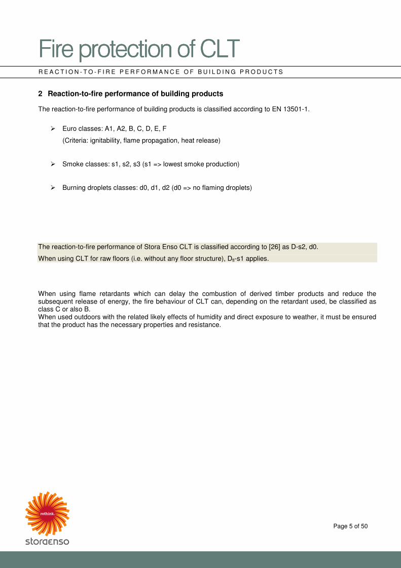
Fig. 2: char layer of an 80 mm CLT element, originally clad with fire protection plasterboard, after a large-scale fire test
�������������A��B�CDE�������������A��B�CDE�������������A��B�CDE�������������A��B�CDE���� ����
Page 5 of 50
R E A C T I O N - T O - F I R E P E R F O R M A N C E O F B U I L D I N G P R O D U C T S 2 Reaction-to-fire performance of building products
The reaction-to-fire performance of building products is classified according to EN 13501-1.
� Euro classes: A1, A2, B, C, D, E, F
(Criteria: ignitability, flame propagation, heat release)
� Smoke classes: s1, s2, s3 (s1 => lowest smoke production)
� Burning droplets classes: d0, d1, d2 (d0 => no flaming droplets)
The reaction-to-fire performance of Stora Enso CLT is classified according to [26] as D-s2, d0.
When using CLT for raw floors (i.e. without any floor structure), Dfl-s1 applies.
When using flame retardants which can delay the combustion of derived timber products and reduce the subsequent release of energy, the fire behaviour of CLT can, depending on the retardant used, be classified as class C or also B. When used outdoors with the related likely effects of humidity and direct exposure to weather, it must be ensured that the product has the necessary properties and resistance.
�������������A��B�CDE�������������A��B�CDE�������������A��B�CDE�������������A��B�CDE���� ����
Page 6 of 50
F I R E R E S I S T A N C E O F B U I L D I N G C O M P O N E N T S 3 Fire resistance of building components
3.1 Classification The performance characteristics and fire resistance duration are defined as follows according to the classification standard EN 13501-2:
� R (Load-bearing capacity) The performance characteristic R is assumed to be satisfied if the load-bearing function of a component subjected to a mechanical load is maintained during the required time of fire exposure.
� E (Integrity) The performance characteristic E of a separating element describes its capacity to resist exposure to fire on one side so that the spread of fire as a result of flames or hot gases to the side not exposed to fire is prevented.
� I (Insulation)
The performance characteristic I is assumed to be satisfied if the average temperature rise over the whole of the non-exposed side caused by one-sided exposure to fire does not exceed 140 °C, and the maximum temperature at any one point does not exceed 180 °C, above ambient temperature. Heat transmission must be limited so that the non-exposed component surface and any neighbouring materials do not catch fire, and so that any persons in the vicinity are protected.
� Additional characteristics are W (thermal radiation), M (resistance to mechanical action), C (self-closing
capability), S (smoke leakage), G (soot fire resistance) and K (fire protection ability), which, in general, are not relevant for conventional CLT components.
The classification time is graduated in periods of 10, 15, 20, 30, 45, 60, 90, 120, 180, 240 and 360 minutes. The direction of the classified fire resistance duration is described with the following abbreviations according to EN 13501-2:
� Classification of façades (curtain-walls) and external walls i � o classified fire resistance duration from inside to outside o � i classified fire resistance duration from outside to inside o � i classified fire resistance duration from inside to outside and from outside to inside
� Classification of ceilings with independent fire resistance
a � b classified fire resistance duration from top to bottom a � b classified fire resistance duration from bottom to top a � b classified fire resistance duration from top to bottom and from bottom to top
�������������A��B�CDE�������������A��B�CDE�������������A��B�CDE�������������A��B�CDE���� ����
Page 7 of 50
F I R E R E S I S T A N C E O F B U I L D I N G C O M P O N E N T S
3.2 Fire protective cladding The designations K1 and K2 for fire protective cladding are described in accordance with EN 13501-2 as follows:
� The term “fire protective cladding” refers to the outermost layer on vertical components and to the lowest layer on horizontal or inclined components.
� The cladding defined by the designation K1 or K2 must provide the protection described in accordance with EN 13501-2 for the layer directly backing the fire protective cladding throughout the corresponding classification period (K1: 10 min.; K2: 10, 30 or 60 min.).
For example, fire protective cladding without an underlying cavity with the classification K2 60 must provide the following protection for a period of 60 minutes:
� During the classification period, the fire protective cladding must not collapse in whole or in part.
� The average temperature recorded on the underside of the supporting plate (on which the fire protective cladding to be classified is tested) must not exceed the ambient temperature by more than 250 °C.
� The maximum temperature recorded on (at any one point) on the underside of the supporting plate (on which the fire protective cladding to be classified is tested) must not exceed the ambient temperature by more than 270 °C.
� After the test, no burned or charred materials should be apparent on any one point of the supporting plate (on which the fire protective cladding to be classified is tested).
Information on the fire protective cladding to be classified can be obtained from gypsum plasterboard manufacturers, among others. 3.3 Fire resistance of CLT components Components with high fire resistance can be produced with multiple layer CLT elements. For example, with a non-clad, three-layer CLT element, the fire resistance REI 60 is already obtained, and with a CLT element clad with a single layer of plasterboard, the fire resistance REI 90 is obtained. In principle, increased requirements for fire resistance can be compensated by the following measures:
� Increase the thickness of the CLT element
� Increase the number of layers of the CLT element
� Apply the corresponding cladding The verification of fire resistance of timber components can either be based on classification reports in accordance with EN 13501-2 on the basis of large-scale fire tests, or on calculations according to EN 1995-1-2, performed in conjunction with the respective national application documents.
�������������A��B�CDE�������������A��B�CDE�������������A��B�CDE�������������A��B�CDE���� ����
Page 8 of 50
V E R I F I C A T I O N O F F I R E R E S I S T A N C E
4 Verification of the fire resistance of CLT elements based on classification reports according to EN 13501-2
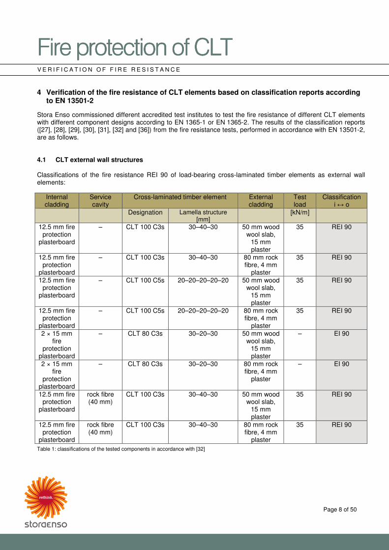
Stora Enso commissioned different accredited test institutes to test the fire resistance of different CLT elements with different component designs according to EN 1365-1 or EN 1365-2. The results of the classification reports ([27], [28], [29], [30], [31], [32] and [36]) from the fire resistance tests, performed in accordance with EN 13501-2, are as follows. 4.1 CLT external wall structures Classifications of the fire resistance REI 90 of load-bearing cross-laminated timber elements as external wall elements:
Internal cladding
Service cavity
Cross-laminated timber element External cladding
Test load
Classification i � o
Designation Lamella structure [mm]
[kN/m]
12.5 mm fire protection
plasterboard
– CLT 100 C3s 30–40–30 50 mm wood wool slab,
15 mm plaster
35 REI 90
12.5 mm fire protection
plasterboard
– CLT 100 C3s 30–40–30 80 mm rock fibre, 4 mm
plaster
35 REI 90
12.5 mm fire protection
plasterboard
– CLT 100 C5s 20–20–20–20–20 50 mm wood wool slab,
15 mm plaster
35 REI 90
12.5 mm fire protection
plasterboard
– CLT 100 C5s 20–20–20–20–20 80 mm rock fibre, 4 mm
plaster
35 REI 90
2 × 15 mm fire
protection plasterboard
– CLT 80 C3s 30–20–30 50 mm wood wool slab,
15 mm plaster
– EI 90
2 × 15 mm fire
protection plasterboard
– CLT 80 C3s 30–20–30 80 mm rock fibre, 4 mm
plaster
– EI 90
12.5 mm fire protection
plasterboard
rock fibre (40 mm)
CLT 100 C3s 30–40–30 50 mm wood wool slab,
15 mm plaster
35 REI 90
12.5 mm fire protection
plasterboard
rock fibre (40 mm)
CLT 100 C3s 30–40–30 80 mm rock fibre, 4 mm
plaster
35 REI 90
Table 1: classifications of the tested components in accordance with [32]

�������������A��B�CDE�������������A��B�CDE�������������A��B�CDE�������������A��B�CDE���� ����
Page 9 of 50
V E R I F I C A T I O N O F F I R E R E S I S T A N C E 4.2 CLT wall structures Classifications of the fire resistance REI 60 of load-bearing cross-laminated timber elements as wall elements:
Cladding Service cavity Cross-laminated timber element Test load
Classification
Designation Lamella structure [mm] [kN/m] – – CLT 100 C3s 30–40–30 35 REI 60 – – CLT 100 C5s 20–20–20–20–20 35 REI 60
12.5 mm fire protection
plasterboard
– CLT 80 C3s 30–20–30 35 REI 60
12.5 mm fire protection
plasterboard
rock fibre (40 mm) CLT 80 C3s 30–20–30 35 REI 60
50 mm Heraklith BM, 5 mm plaster
– CLT 80 C3s 30–20–30 35 REI 60
Table 2: classifications of the tested components in accordance with [27] Classifications of the fire resistance REI 90 or EI 90 of load-bearing cross-laminated timber elements as wall elements:
Cladding Cavity Cross-laminated timber element Test load
Classification
Designation Lamella structure [mm] [kN/m] 12.5 mm fire
protection plasterboard
– CLT 100 C3s 30–40–30 35 REI 90
12.5 mm fire protection
plasterboard
– CLT 100 C5s 20–20–20–20–20 35 REI 90
12.5 mm fire protection
plasterboard
rock fibre (40 mm) CLT 100 C3s 30–40–30 35 REI 90
2 × 15 mm fire protection
plasterboard
– CLT 80 C3s 30–20–30 – EI 90
Table 3: classifications of the tested components in accordance with [28]
Cladding Cavity Cross-laminated timber element Test load
Classification
Designation Lamella structure [mm] [kN/m] 35 mm ProCrea clay
board, 5 mm ProCrea clay plaster with reinforcement
fabric, 5 mm ProCrea clay plaster
– CLT 140 C5s 40–20–20–20–40 280 REI 90
Table 4: classification of the tested components in accordance with [36]
�������������A��B�CDE�������������A��B�CDE�������������A��B�CDE�������������A��B�CDE���� ����
Page 10 of 50
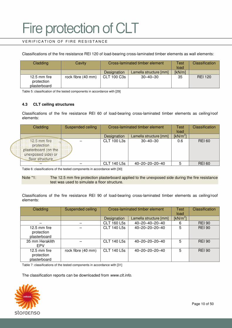
V E R I F I C A T I O N O F F I R E R E S I S T A N C E Classifications of the fire resistance REI 120 of load-bearing cross-laminated timber elements as wall elements:
Cladding Cavity Cross-laminated timber element Test load
Classification
Designation Lamella structure [mm] [kN/m] 12.5 mm fire
protection plasterboard
rock fibre (40 mm) CLT 100 C3s 30–40–30 35 REI 120
Table 5: classification of the tested components in accordance with [29] 4.3 CLT ceiling structures Classifications of the fire resistance REI 60 of load-bearing cross-laminated timber elements as ceiling/roof elements:
Cladding Suspended ceiling Cross-laminated timber element Test load
Classification
Designation Lamella structure [mm] [kN/m2] 12.5 mm fire
protection plasterboard (on the unexposed side) or
floor structure
– CLT 100 L3s 30–40–30 0.6 REI 60
– – CLT 140 L5s 40–20–20–20–40 5 REI 60
Table 6: classifications of the tested components in accordance with [30] Note *1: The 12.5 mm fire protection plasterboard applied to the unexposed side during the fire resistance
test was used to simulate a floor structure. Classifications of the fire resistance REI 90 of load-bearing cross-laminated timber elements as ceiling/roof elements:
Cladding Suspended ceiling Cross-laminated timber element Test load
Classification
Designation Lamella structure [mm] [kN/m2] – – CLT 160 L5s 40–20–40–20–40 6 REI 90
12.5 mm fire protection
plasterboard
– CLT 140 L5s 40–20–20–20–40 5 REI 90
35 mm Heraklith EPV
– CLT 140 L5s 40–20–20–20–40 5 REI 90
12.5 mm fire protection
plasterboard
rock fibre (40 mm) CLT 140 L5s 40–20–20–20–40 5 REI 90
Table 7: classifications of the tested components in accordance with [31]
The classification reports can be downloaded from www.clt.info.
*1
�������������A��B�������������A��B�������������A��B�������������A��B����CDECDECDECDE���� ����
Page 11 of 50
V E R I F I C A T I O N O F F I R E R E S I S T A N C E
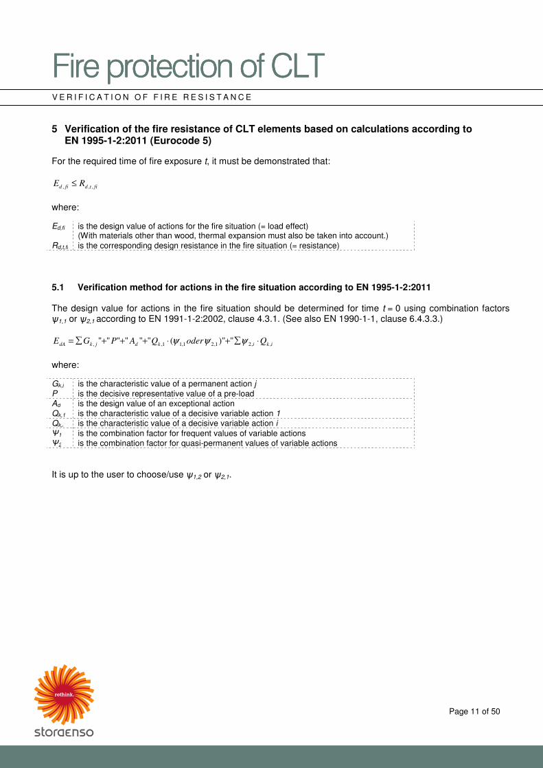
5 Verification of the fire resistance of CLT elements based on calculations according to EN 1995-1-2:2011 (Eurocode 5)
For the required time of fire exposure t, it must be demonstrated that:
fitdfid RE ,,, ≤ where: Ed,fi is the design value of actions for the fire situation (= load effect)
(With materials other than wood, thermal expansion must also be taken into account.) Rd,t,fi is the corresponding design resistance in the fire situation (= resistance) 5.1 Verification method for actions in the fire situation according to EN 1995-1-2:2011 The design value for actions in the fire situation should be determined for time t = 0 using combination factors �1,1 or �2,1 according to EN 1991-1-2:2002, clause 4.3.1. (See also EN 1990-1-1, clause 6.4.3.3.)
ikikdjkdA QoderQAPGE ,,21,21,11,, ")"("""""" ⋅�+⋅+++�= ψψψ
where: Gk,j is the characteristic value of a permanent action j P is the decisive representative value of a pre-load Ad is the design value of an exceptional action Qk,1 is the characteristic value of a decisive variable action 1
Qk,i is the characteristic value of a decisive variable action i �1 is the combination factor for frequent values of variable actions �2 is the combination factor for quasi-permanent values of variable actions It is up to the user to choose/use �1,2 or �2,1.
�������������A��B�������������A��B�������������A��B�������������A��B����CDECDECDECDE���� ����
Page 12 of 50
V E R I F I C A T I O N O F F I R E R E S I S T A N C E
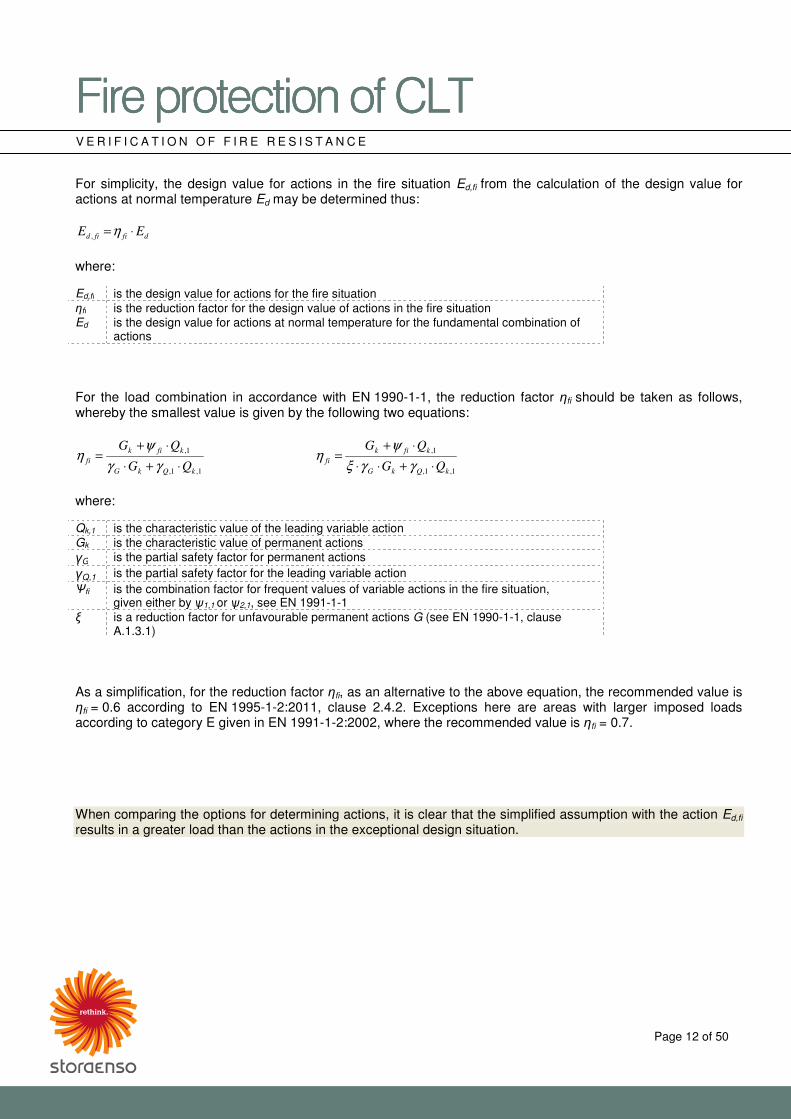
For simplicity, the design value for actions in the fire situation Ed,fi from the calculation of the design value for actions at normal temperature Ed may be determined thus:
dfifid EE ⋅=η,
where: Ed,fi is the design value for actions for the fire situation �fi is the reduction factor for the design value of actions in the fire situation Ed is the design value for actions at normal temperature for the fundamental combination of
actions For the load combination in accordance with EN 1990-1-1, the reduction factor �fi should be taken as follows, whereby the smallest value is given by the following two equations:
1,1,
1,
kQkG
kfik
fiQG
QG
⋅+⋅
⋅+=
γγ
ψη
1,1,
1,
kQkG
kfik
fiQG
QG
⋅+⋅⋅
⋅+=
γγξ
ψη
where: Qk,1 is the characteristic value of the leading variable action Gk is the characteristic value of permanent actions �G is the partial safety factor for permanent actions �Q,1 is the partial safety factor for the leading variable action �fi is the combination factor for frequent values of variable actions in the fire situation,
given either by �1,1 or �2,1, see EN 1991-1-1 � is a reduction factor for unfavourable permanent actions G (see EN 1990-1-1, clause
A.1.3.1) As a simplification, for the reduction factor �fi, as an alternative to the above equation, the recommended value is �fi = 0.6 according to EN 1995-1-2:2011, clause 2.4.2. Exceptions here are areas with larger imposed loads according to category E given in EN 1991-1-2:2002, where the recommended value is �fi = 0.7. When comparing the options for determining actions, it is clear that the simplified assumption with the action Ed,fi
results in a greater load than the actions in the exceptional design situation.
�������������A��B�������������A��B�������������A��B�������������A��B����CDECDECDECDE���� ����
Page 13 of 50
V E R I F I C A T I O N O F F I R E R E S I S T A N C E
5.2 Verification method for mechanical resistance in the fire situation according to EN 1995-1-2:2011 For verification of mechanical resistance, the design values of strength and stiffness properties shall be determined from:
fiM
f
fifid kf,
20
mod,, γ⋅=
where: fd,fi is the design value of strength in fire kmod,fi is the modification factor in the fire situation for the reduced cross-section method:
kmod,fi = 1.0 (as per EN 1995-1-2) f20 is the 20% fractile value of a strength property at normal temperature;
f20 = kfi × fk fk is the 5% fractile value of a strength property kfi is the coefficient for converting 5% to 20% fractile values;
kfi for CLT = 1.15 (as per EN 1995-1-2) �M,fi is the partial safety factor for timber in fire
�M,fi = 1.0 (as per EN 1995-1-2) For the calculation in the fire situation, instead of the 5% fractile values, the 20% fractiles are used. The reason for this assumption lies in the extremely low probability of occurrence of a fully developed fire during the lifetime of a supporting structure, and does not depend on the material. [25] (Hence the coefficient for converting the fractile value kfi with 1.15.)
fiM
S
fifid kS,
20
mod,, γ⋅=
where: Sd,fi is the design value of the stiffness property (modulus of elasticity or shear modulus) in the
fire situation kmod,fi is the modification factor in the fire situation for the reduced cross-section method:
kmod,fi = 1.0 (as per EN 1995-1-2) S20 is the 20% fractile of a stiffness property (modulus of elasticity or shear modulus) at
normal temperature S20 = kfi × S05
S05 is the 5% fractile of a stiffness property (modulus of elasticity or shear modulus) at normal temperature
kfi is the coefficient for converting 5% to 20% fractile values; kfi for CLT = 1.15 (as per EN 1995-1-2)
�M,fi is the partial safety factor for timber in fire �M,fi = 1.0 (as per EN 1995-1-2)
�������������A��B�������������A��B�������������A��B�������������A��B����CDECDECDECDE���� ����
Page 14 of 50
V E R I F I C A T I O N O F F I R E R E S I S T A N C E
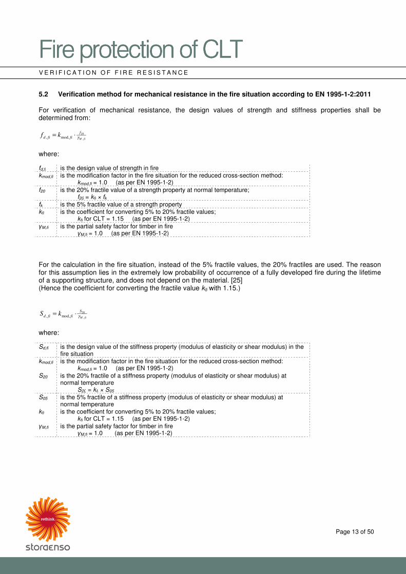
5.3 Charring rates for Stora Enso CLT During exposure to fire and to the resulting effect of temperature on the CLT cross-section, the use of polyurethane adhesives between individual layers can lead to softening. A possible consequence of this may be that small sections of the heat-insulating char layer fall off, and the protective function of this layer may be lost at certain points. [2] Therefore, in the case of ceiling elements and other horizontal components, possible delaminations must be taken into account, and, for the subsequent fire-exposed layers, it is necessary to mathematically estimate an increased charring rate until the formation of a new 25 mm-thick char layer. 5.3.1 Design value of charring rates �0 for CLT on surfaces which are unprotected throughout the duration of
the fire The following charring rates for Stora Enso CLT were determined as part of [8] by the accredited institute Holzforschung Austria, and may be used for the calculation of the fire resistance of constructions with different loads and/or layer thicknesses according to EN 1995-1-2 (with reference to the respective national annex).
� Ceiling and roof elements (horizontal components):
o 0.65 mm/min., if only one layer is affected by exposure to fire. [33]
o 1.3 mm/min. for any additional layers affected by exposure to fire until charring or the formation
of a 25 mm-thick char layer. Thereafter, a charring rate of 0.65 mm/min. can be applied up to the next bonded joint. [33]
Fig. 3: diagram illustrating an example of charring or the charring rate of a horizontal CLT component (CLT 180 L5s), which explains the mathematically estimated charring rate of 1.3 mm/min. for each additional layer affected by fire until the formation of a new 25 mm-thick char layer.
�������������A��B�������������A��B�������������A��B�������������A��B����CDECDECDECDE���� ����
Page 15 of 50
V E R I F I C A T I O N O F F I R E R E S I S T A N C E
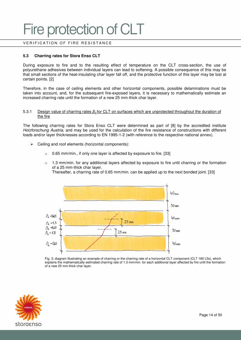
� Wall element (vertical components):
o 0.63 mm/min., if only one layer is affected by exposure to fire. [33]
o 0.86 mm/min. for each additional layer affected by exposure to fire. [33]
Fig. 4: diagram showing an example of charring or the charring rate of a vertical CLT component (CLT 100 L5s), which explains the mathematically estimated increased charring rate of 0.86 mm/min. from the second layer affected by fire.
�������������A��B�������������A��B�������������A��B�������������A��B����CDECDECDECDE���� ����
Page 16 of 50
V E R I F I C A T I O N O F F I R E R E S I S T A N C E
5.3.2 Design value of charring rates �0 for CLT on surfaces which are initially protected from exposure to fire
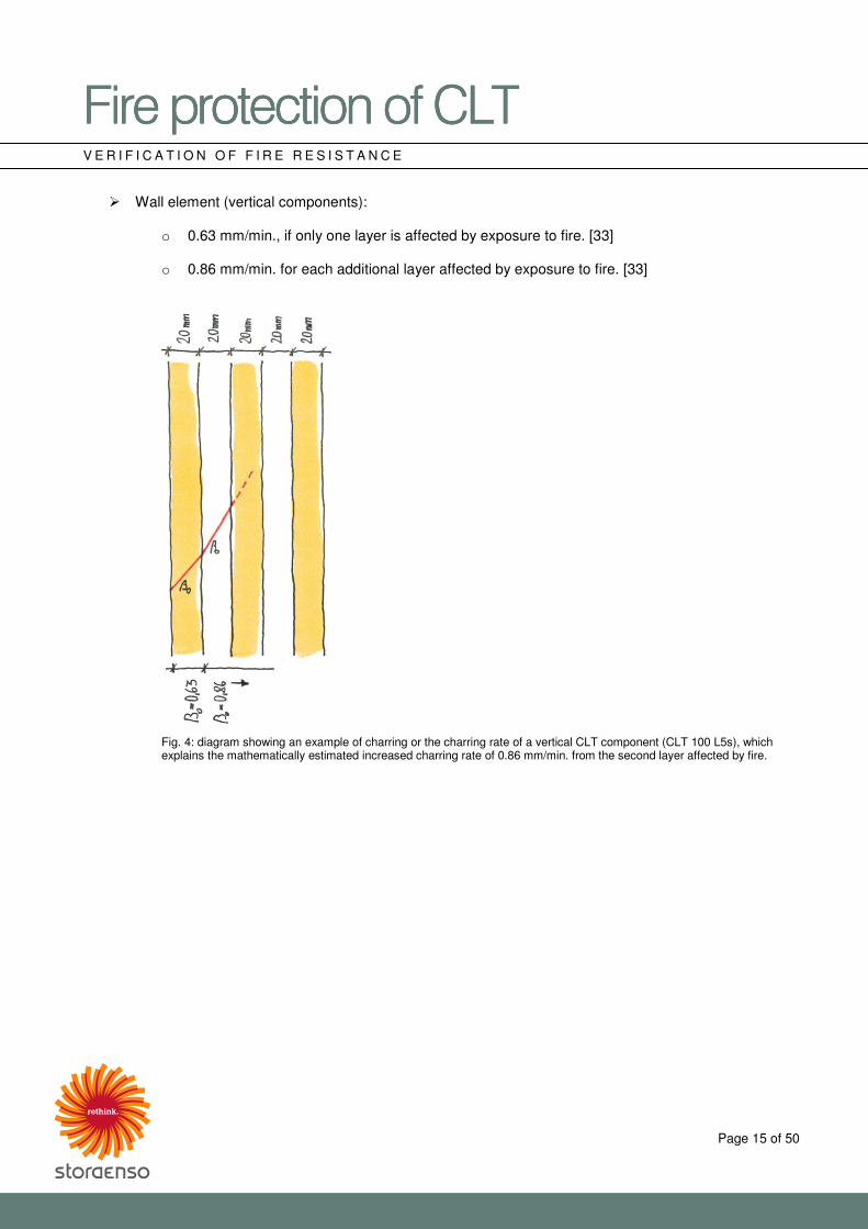
by gypsum plasterboard The fire resistance rating of components is determined during exposure to fire on the inside of a room predominantly by interior cladding. To increase the fire resistance of structures such as wall, ceiling or roof elements, plaster building materials/gypsum plasterboards are generally used as, even if they are not very thick, they provide effective protection. Effective protection is based particularly on the combined crystal water in the panels’ gypsum core which has a concentration of approx. 20%. Energy is consumed by the evaporation of this crystal water, and a protective steam curtain is also formed on the fire-exposed side of the component. In addition to delaying the spread of fire, the dehydrated gypsum layer also acts as insulation through the declining thermal conductivity. Fire protection plasterboard also contains glass fibre which reinforces the gypsum core and ensures structural cohesion when exposed to fire. [3]
Fig. 5: two-ply fire protection plasterboard cladding exposed to fire during a large-scale fire test Figure 5 illustrates the behaviour of fire protection plasterboard when exposed to fire; in this case there are two layers of cladding. As can be seen, after crazing and detaching of the char layer, as time progresses, large gaps appear between the joints, the joint plaster compound fails and the first section of the first plasterboard layer falls off. If larger panel sections fall away from the first layer, crazing also occurs in the second layer. After gaps appear in this layer’s joints, the flames spread through the increasing gaps in the joints towards the underlying CLT which leads to the production and emission of wood gas. Charring starts on the initially protected CLT element. The following correlation or equivalence with regard to gypsum plasterboard designations should be noted:
Designation according to EN 520 Designation according to ÖNORM B 3410 and DIN 18180
Gypsum plasterboard, type A Plasterboard cladding Gypsum plasterboard, type F or DF
Fire protection plasterboard
Gypsum plasterboard, type H2 Plasterboard cladding – waterproofed Gypsum plasterboard, type DFH2 Fire protection plasterboard – waterproofed
Table 8: comparison of gypsum plasterboard designations by EN 520 and ÖNORM B 3410 or DIN 18180
�������������A��B�������������A��B�������������A��B�������������A��B����CDECDECDECDE���� ����
Page 17 of 50
V E R I F I C A T I O N O F F I R E R E S I S T A N C E
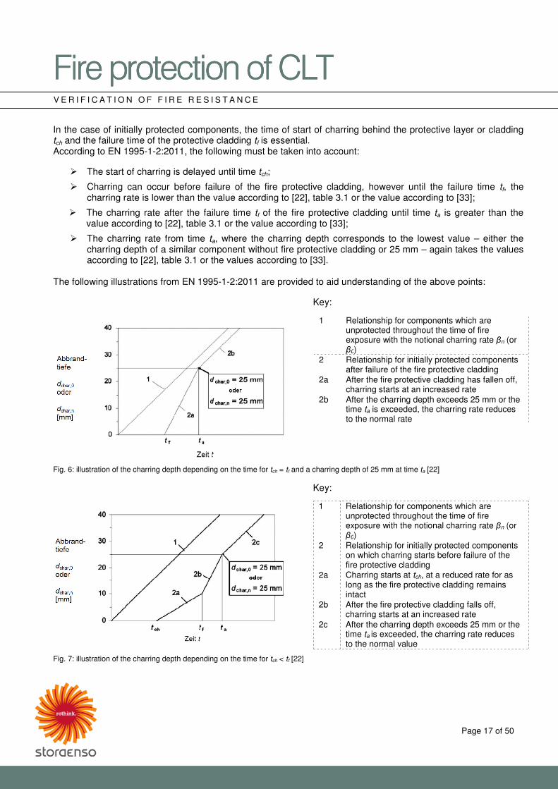
In the case of initially protected components, the time of start of charring behind the protective layer or cladding tch and the failure time of the protective cladding tf is essential. According to EN 1995-1-2:2011, the following must be taken into account:
� The start of charring is delayed until time tch;
� Charring can occur before failure of the fire protective cladding, however until the failure time tf, the charring rate is lower than the value according to [22], table 3.1 or the value according to [33];
� The charring rate after the failure time tf of the fire protective cladding until time ta is greater than the value according to [22], table 3.1 or the value according to [33];
� The charring rate from time ta, where the charring depth corresponds to the lowest value – either the charring depth of a similar component without fire protective cladding or 25 mm – again takes the values according to [22], table 3.1 or the values according to [33].
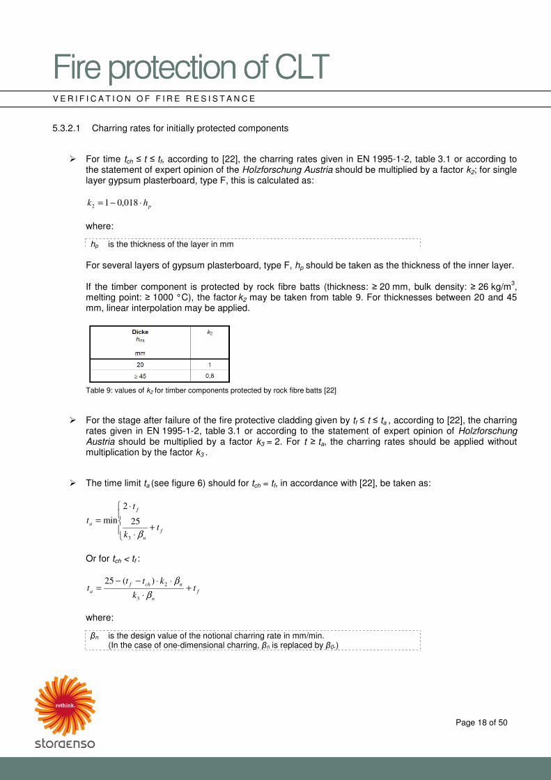
The following illustrations from EN 1995-1-2:2011 are provided to aid understanding of the above points: Key:
1 Relationship for components which are unprotected throughout the time of fire exposure with the notional charring rate �n (or �0)
2 Relationship for initially protected components after failure of the fire protective cladding
2a After the fire protective cladding has fallen off, charring starts at an increased rate
2b After the charring depth exceeds 25 mm or the time ta is exceeded, the charring rate reduces to the normal rate
Fig. 6: illustration of the charring depth depending on the time for tch = tf and a charring depth of 25 mm at time ta [22] Key:
1 Relationship for components which are unprotected throughout the time of fire exposure with the notional charring rate �n (or �0)
2 Relationship for initially protected components on which charring starts before failure of the fire protective cladding
2a Charring starts at tch, at a reduced rate for as long as the fire protective cladding remains intact
2b After the fire protective cladding falls off, charring starts at an increased rate
2c After the charring depth exceeds 25 mm or the time ta is exceeded, the charring rate reduces to the normal value
Fig. 7: illustration of the charring depth depending on the time for tch < tf [22]
�������������A��B�������������A��B�������������A��B�������������A��B����CDECDECDECDE���� ����
Page 18 of 50
V E R I F I C A T I O N O F F I R E R E S I S T A N C E
5.3.2.1 Charring rates for initially protected components
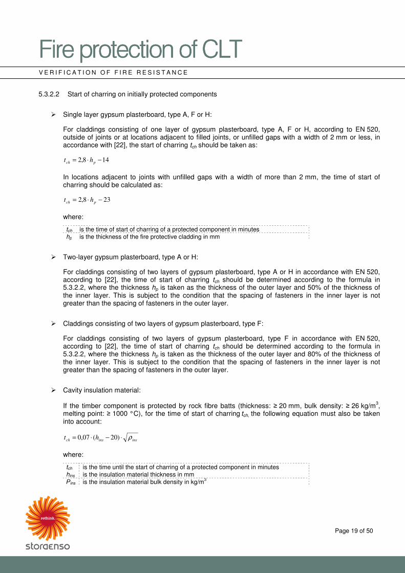
� For time tch � t � tf, according to [22], the charring rates given in EN 1995-1-2, table 3.1 or according to the statement of expert opinion of the Holzforschung Austria should be multiplied by a factor k2; for single layer gypsum plasterboard, type F, this is calculated as:
phk ⋅−= 018,012
where:
hp is the thickness of the layer in mm
For several layers of gypsum plasterboard, type F, hp should be taken as the thickness of the inner layer.
If the timber component is protected by rock fibre batts (thickness: � 20 mm, bulk density: � 26 kg/m3, melting point: � 1000 °C), the factor k2 may be taken from table 9. For thicknesses between 20 and 45 mm, linear interpolation may be applied.
Table 9: values of k2 for timber components protected by rock fibre batts [22]
� For the stage after failure of the fire protective cladding given by tf � t � ta , according to [22], the charring rates given in EN 1995-1-2, table 3.1 or according to the statement of expert opinion of Holzforschung Austria should be multiplied by a factor k3 = 2. For t � ta, the charring rates should be applied without multiplication by the factor k3 .
� The time limit ta (see figure 6) should for tch = tf, in accordance with [22], be taken as:
��
��
�
+⋅
⋅
=f
n
f
at
k
t
t
β3
25
2
min
Or for tch < tf :
f
n
nchf
a tk
kttt +
⋅
⋅⋅−−=
β
β
3
2)(25
where:
�n is the design value of the notional charring rate in mm/min. (In the case of one-dimensional charring, �n is replaced by �0.)
�������������A��B�������������A��B�������������A��B�������������A��B����CDECDECDECDE���� ����
Page 19 of 50
V E R I F I C A T I O N O F F I R E R E S I S T A N C E
5.3.2.2 Start of charring on initially protected components
� Single layer gypsum plasterboard, type A, F or H:
For claddings consisting of one layer of gypsum plasterboard, type A, F or H, according to EN 520, outside of joints or at locations adjacent to filled joints, or unfilled gaps with a width of 2 mm or less, in accordance with [22], the start of charring tch should be taken as:
148,2 −⋅= pch ht
In locations adjacent to joints with unfilled gaps with a width of more than 2 mm, the time of start of charring should be calculated as:
238,2 −⋅= pch ht
where:
tch is the time of start of charring of a protected component in minutes hp is the thickness of the fire protective cladding in mm
� Two-layer gypsum plasterboard, type A or H:
For claddings consisting of two layers of gypsum plasterboard, type A or H in accordance with EN 520, according to [22], the time of start of charring tch should be determined according to the formula in 5.3.2.2, where the thickness hp is taken as the thickness of the outer layer and 50% of the thickness of the inner layer. This is subject to the condition that the spacing of fasteners in the inner layer is not greater than the spacing of fasteners in the outer layer.
� Claddings consisting of two layers of gypsum plasterboard, type F:
For claddings consisting of two layers of gypsum plasterboard, type F in accordance with EN 520, according to [22], the time of start of charring tch should be determined according to the formula in 5.3.2.2, where the thickness hp is taken as the thickness of the outer layer and 80% of the thickness of the inner layer. This is subject to the condition that the spacing of fasteners in the inner layer is not greater than the spacing of fasteners in the outer layer.
� Cavity insulation material:
If the timber component is protected by rock fibre batts (thickness: � 20 mm, bulk density: � 26 kg/m3, melting point: � 1000 °C), for the time of start of charring tch, the following equation must also be taken into account:
insinsch ht ρ⋅−⋅= )20(07,0
where:
tch is the time until the start of charring of a protected component in minutes hins is the insulation material thickness in mm �ins is the insulation material bulk density in kg/m3
�������������A��B�������������A��B�������������A��B�������������A��B����CDECDECDECDE���� ����
Page 20 of 50
V E R I F I C A T I O N O F F I R E R E S I S T A N C E
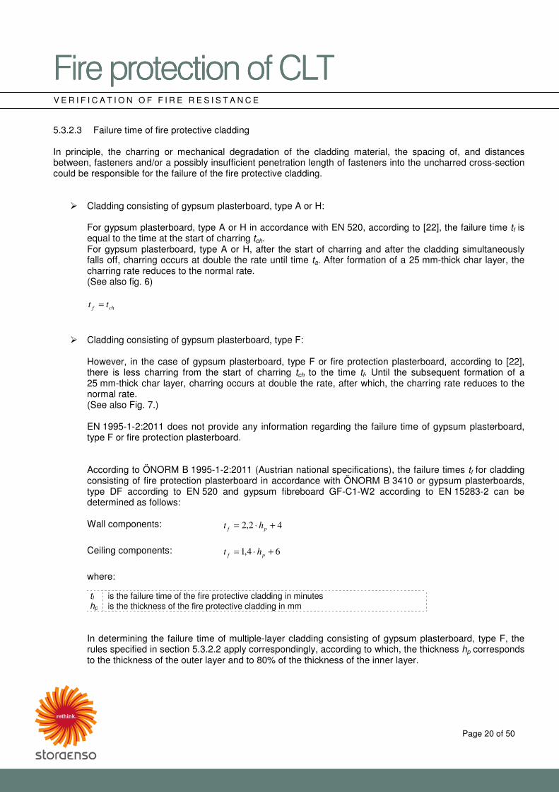
5.3.2.3 Failure time of fire protective cladding In principle, the charring or mechanical degradation of the cladding material, the spacing of, and distances between, fasteners and/or a possibly insufficient penetration length of fasteners into the uncharred cross-section could be responsible for the failure of the fire protective cladding.
� Cladding consisting of gypsum plasterboard, type A or H:
For gypsum plasterboard, type A or H in accordance with EN 520, according to [22], the failure time tf is equal to the time at the start of charring tch. For gypsum plasterboard, type A or H, after the start of charring and after the cladding simultaneously falls off, charring occurs at double the rate until time ta. After formation of a 25 mm-thick char layer, the charring rate reduces to the normal rate. (See also fig. 6)
chf tt =
� Cladding consisting of gypsum plasterboard, type F:
However, in the case of gypsum plasterboard, type F or fire protection plasterboard, according to [22], there is less charring from the start of charring tch to the time tf. Until the subsequent formation of a 25 mm-thick char layer, charring occurs at double the rate, after which, the charring rate reduces to the normal rate. (See also Fig. 7.)
EN 1995-1-2:2011 does not provide any information regarding the failure time of gypsum plasterboard,
type F or fire protection plasterboard. According to ÖNORM B 1995-1-2:2011 (Austrian national specifications), the failure times tf for cladding consisting of fire protection plasterboard in accordance with ÖNORM B 3410 or gypsum plasterboards, type DF according to EN 520 and gypsum fibreboard GF-C1-W2 according to EN 15283-2 can be determined as follows:
Wall components: 42,2 +⋅= pf ht
Ceiling components: 64,1 +⋅= pf ht
where:
tf is the failure time of the fire protective cladding in minutes hp is the thickness of the fire protective cladding in mm
In determining the failure time of multiple-layer cladding consisting of gypsum plasterboard, type F, the
rules specified in section 5.3.2.2 apply correspondingly, according to which, the thickness hp corresponds to the thickness of the outer layer and to 80% of the thickness of the inner layer.
�������������A��B�������������A��B�������������A��B�������������A��B����CDECDECDECDE���� ����
Page 21 of 50
V E R I F I C A T I O N O F F I R E R E S I S T A N C E
� Penetration length of fasteners for gypsum plasterboard
In addition to thermal degradation of the cladding material, the fire protective cladding can also fall off due to the pull-out failure of fasteners. According to [22], the required minimum length of the fasteners should also be determined in order to eliminate the fact that pull-out of the fasteners is a relevant factor for the failure of the fire protective cladding.
The minimum penetration length of the fastener la into the unburnt cross-section should be taken as 10 mm. The required penetration length of the fastener lf,req is calculated as follows:
acharpreqf ldhl ++= 0,,
where:
hp is the panel thickness in mm dchar,0 is the charring depth in the timber component la is the minimum penetration length of the fastener into the unburnt wood
For more information on cladding fasteners/penetration lengths, see [22], section 7.1.2.
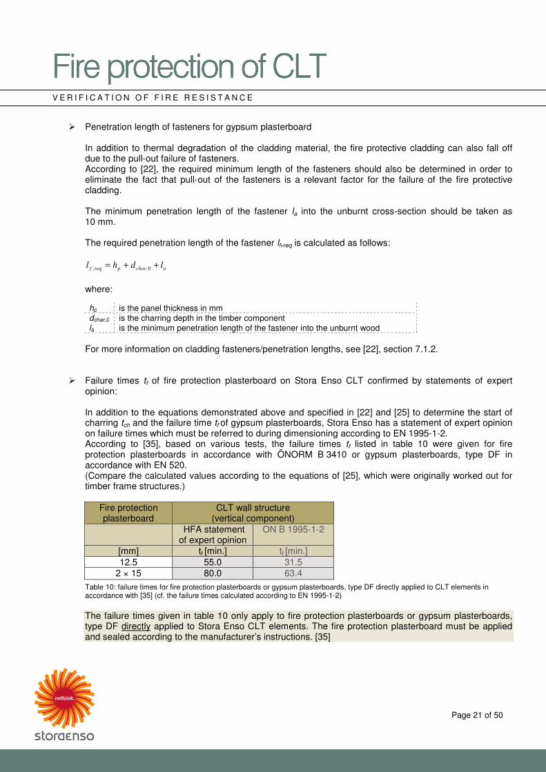
� Failure times tf of fire protection plasterboard on Stora Enso CLT confirmed by statements of expert opinion:
In addition to the equations demonstrated above and specified in [22] and [25] to determine the start of charring tch and the failure time tf of gypsum plasterboards, Stora Enso has a statement of expert opinion on failure times which must be referred to during dimensioning according to EN 1995-1-2. According to [35], based on various tests, the failure times tf listed in table 10 were given for fire protection plasterboards in accordance with ÖNORM B 3410 or gypsum plasterboards, type DF in accordance with EN 520. (Compare the calculated values according to the equations of [25], which were originally worked out for timber frame structures.)
Fire protection plasterboard
CLT wall structure (vertical component)
HFA statement of expert opinion
ON B 1995-1-2
[mm] tf [min.] tf [min.] 12.5 55.0 31.5
2 × 15 80.0 63.4
Table 10: failure times for fire protection plasterboards or gypsum plasterboards, type DF directly applied to CLT elements in accordance with [35] (cf. the failure times calculated according to EN 1995-1-2)
The failure times given in table 10 only apply to fire protection plasterboards or gypsum plasterboards, type DF directly applied to Stora Enso CLT elements. The fire protection plasterboard must be applied and sealed according to the manufacturer’s instructions. [35]
�������������A��B�������������A��B�������������A��B�������������A��B����CDECDECDECDE���� ����
Page 22 of 50
V E R I F I C A T I O N O F F I R E R E S I S T A N C E
5.4 Determining the load-bearing capacity (R) of CLT elements according to EN 1995-1-2:2011 When determining the load-bearing capacity (R) of timber components exposed to fire, or when calculating cross-sectional values, in addition to determining the charring area, the underlying area affected by temperature must also be taken into account because the wood’s strength and stiffness properties decrease as the temperature rises. As an alternative to the calculation option specified in EN 1995-1-2, annex B, the cross-sectional values can also be calculated using two simplified methods. We recommend the first method:
� Reduced cross-section method For verification in the fire situation, this method uses a reduced cross-section or residual cross-section, calculated on the basis of increased charring (roundings or corner charring), and an additional area affected by temperature (reduction of mechanical properties due to the effect of temperature).
� Reduced properties method As an alternative to the reduced cross-section method – calculated with charring speed and corner charring – this method takes into account the reduction of mechanical properties depending on the type of load and cross-section.
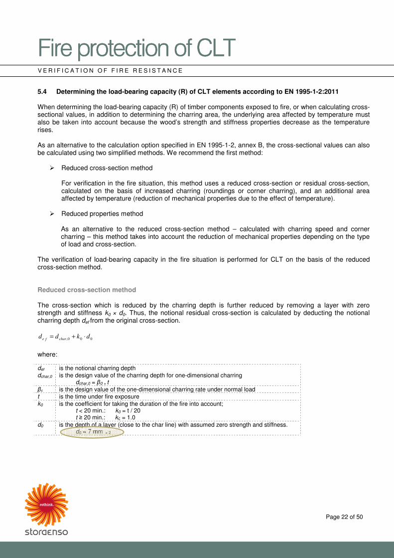
The verification of load-bearing capacity in the fire situation is performed for CLT on the basis of the reduced cross-section method. Reduced cross-section method The cross-section which is reduced by the charring depth is further reduced by removing a layer with zero strength and stiffness k0 × d0. Thus, the notional residual cross-section is calculated by deducting the notional charring depth def from the original cross-section.
000, dkdd charfe ⋅+=
where: def is the notional charring depth dchar,0 is the design value of the charring depth for one-dimensional charring
dchar,0 = �0 × t �n is the design value of the one-dimensional charring rate under normal load t is the time under fire exposure k0 is the coefficient for taking the duration of the fire into account;
t < 20 min.: k0 = t / 20 t � 20 min.: k0 = 1.0
d0 is the depth of a layer (close to the char line) with assumed zero strength and stiffness. d0 = 7 mm
× 2
�������������A��B�������������A��B�������������A��B�������������A��B����CDECDECDECDE���� ����
Page 23 of 50
V E R I F I C A T I O N O F F I R E R E S I S T A N C E
Note *2: The value specified for d0 = 7 mm is based on [26] (relating to [22]). The value d0 of 7 mm (for the simplified calculation method of the reduced cross-section method)
is currently being discussed by scientists around the world, however no unified opinion has been established.
Possible national regulations on d0 must be taken into account. With regard to assumptions about charring rates for Stora Enso CLT, the following must be observed:
� When using CLT for flat components (wall and ceiling structures), one-dimensional charring rates in accordance with [33] (see section 5.3.1) should be used.
� When using CLT for supports (edgewise), for example, proceed according to [22], section 3.4.2. In doing so, for CLT cross-sections with original widths which do not meet requirements, increased charring rates should be expected.
When verifying the load-bearing capacity in the fire situation of Stora Enso CLT components, the following must be observed:
� Charring on both sides must be taken into account on load-bearing elements with no separating function. [22]
� Possible additional, eccentric load applications due to one-sided charring must be taken into account particularly on thinner CLT elements.
� Residual cross-sections of layers � 3 mm are not used in the remaining calculations. (This assumption takes into account the generally non-linear nature of the char line.)
The remaining calculation steps and verifications are performed in the same way as the cold calculations.
�������������A��B�������������A��B�������������A��B�������������A��B����CDECDECDECDE���� ����
Page 24 of 50
V E R I F I C A T I O N O F F I R E R E S I S T A N C E
5.5 Determining the integrity (E) and insulation (I) of CLT elements The following options exist for verification of integrity (E) and insulation (I):
� Calculation method according to EN 1995-1-2:2011, annex E ([22])
� Model according to ÖNORM B 1995-1-2:2011, 14.3 ([25]) or the European guideline “Fire safety in timber buildings” ([9]) or the dissertation by Ms Schleifer ([4])
� Structures without additional verifications according to ÖNORM B 1995-1-2:2011 ([25]) Verification of the integrity and insulation of CLT can be performed using the model specified in ÖNORM B 1995-1-2:2011 ([25]) or in the European technical guideline “Fire safety in timber buildings” ([9]) and elaborated by [4], which have the same approach/support the same theory. If we compare this model with the calculation method specified in EN 1995-1-2:2011, annex E, the possibility of an unlimited variation of materials and number of layers can be considered to be a significant advantage. Extended method for determining the integrity (EI) of wall and ceiling structures in accordance with ÖNORM B 1995-1-2:2011 ([25]) or the European guideline “Fire safety in timber buildings” ([9]) In principle, the following applies to the calculation:
� The influence of temperature according to the uniform temperature curve as per EN 1991-1-2 provides the basis for the calculation model.
� According to [25], the calculation model is limited to a fire resistance duration of 60 minutes.
Validation calculations performed by the accredited institute Holzforschung Austria as part of large-scale fire tests show that this model can also be used for a fire resistance duration of 90 minutes. [5]
� The requirement for integrity (E) is considered satisfied if the requirement for the insulation (I) criterion is shown to be positive.
� The requirement for insulation (I) is satisfied if the average temperature rise on the unexposed side of the component does not exceed 140 °C, or 180 °C at any one point (above the ambient temperature).
� In order to ensure the calculated fire resistance or integrity, in the case of composite timber components, the surplus insulation must be prevented from falling out after failure of the cladding by mechanical means, where appropriate. It must also be ensured, through correct installation according to the manufacturer’s instructions (e.g. information relating to spacing between fasteners and penetration lengths), that the cladding on the unexposed side cannot fall off at an early stage.
�������������A��B�������������A��B�������������A��B�������������A��B����CDECDECDECDE���� ����
Page 25 of 50
V E R I F I C A T I O N O F F I R E R E S I S T A N C E
The component may be composed of any of the following panel and insulation materials and may be designed with a cavity: Panel materials (fasteners according to the manufacturer’s instructions):
� Solid wood panels of at least C 24 in accordance with EN 338 � OSB panels in accordance with EN 300 � Particle board (chipboard) in accordance with EN 309 � Gypsum plasterboard, type A, H and F in accordance with EN 520 � Gypsum fibreboard in accordance with EN 15283-2
Insulation material (surplus installation according to the manufacturer’s instructions):
� Rock fibre in accordance with EN 13162 � Glass wool in accordance with EN 13162
The required integrity of a component is considered satisfied if the following equation is satisfied:
reqins tt ≥
where: tins is the time until failure of the separating function of the entire component, in minutes. treq is the required fire resistance duration for the separating function of the entire component,
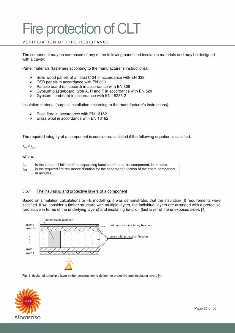
in minutes. 5.5.1 The insulating and protective layers of a component Based on simulation calculations or FE modelling, it was demonstrated that the insulation (I) requirements were satisfied. If we consider a timber structure with multiple layers, the individual layers are arranged with a protective (protective in terms of the underlying layers) and insulating function (last layer of the unexposed side). [4]
Fig. 8: design of a multiple layer timber construction to define the protective and insulating layers [4]
�������������A��B�������������A��B�������������A��B�������������A��B����CDECDECDECDE���� ����
Page 26 of 50
V E R I F I C A T I O N O F F I R E R E S I S T A N C E
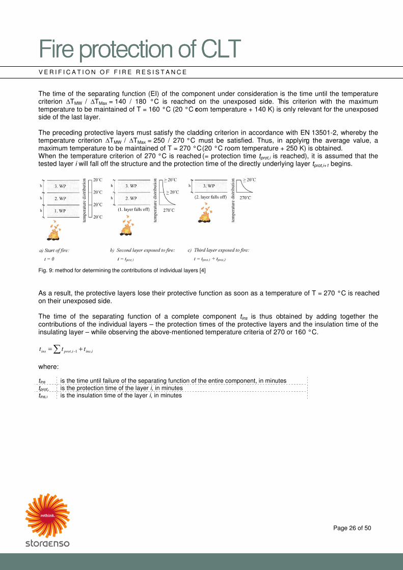
The time of the separating function (EI) of the component under consideration is the time until the temperature criterion �TMW / �TMax = 140 / 180 °C is reached on the unexposed side. This criterion with the maximum temperature to be maintained of T = 160 °C (20 °C room temperature + 140 K) is only relevant for the unexposed side of the last layer. The preceding protective layers must satisfy the cladding criterion in accordance with EN 13501-2, whereby the temperature criterion �TMW / �TMax = 250 / 270 °C must be satisfied. Thus, in applying the average value, a maximum temperature to be maintained of T = 270 °C (20 °C room temperature + 250 K) is obtained. When the temperature criterion of 270 °C is reached (= protection time tprot,i is reached), it is assumed that the tested layer i will fall off the structure and the protection time of the directly underlying layer tprot,i+1 begins.
Fig. 9: method for determining the contributions of individual layers [4] As a result, the protective layers lose their protective function as soon as a temperature of T = 270 °C is reached on their unexposed side. The time of the separating function of a complete component tins is thus obtained by adding together the contributions of the individual layers – the protection times of the protective layers and the insulation time of the insulating layer – while observing the above-mentioned temperature criteria of 270 or 160 °C.
� += − iinsiprotins ttt ,1,
where: tins is the time until failure of the separating function of the entire component, in minutes tprot,i is the protection time of the layer i, in minutes tins,i is the insulation time of the layer i, in minutes
�������������A��B�������������A��B�������������A��B�������������A��B����CDECDECDECDE���� ����
Page 27 of 50
V E R I F I C A T I O N O F F I R E R E S I S T A N C E
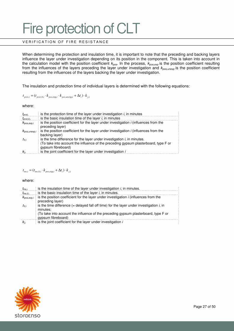
When determining the protection and insulation time, it is important to note that the preceding and backing layers influence the layer under investigation depending on its position in the component. This is taken into account in the calculation model with the position coefficient kpos. In the process, kpos,exp is the position coefficient resulting from the influences of the layers preceding the layer under investigation and kpos,unexp is the position coefficient resulting from the influences of the layers backing the layer under investigation. The insulation and protection time of individual layers is determined with the following equations:
ijiiunposiposiprotiprot ktkktt ,exp,,,exp,,0,, )( ⋅∆+⋅⋅=
where: tprot,i is the protection time of the layer under investigation i, in minutes tprot,0,i is the basic insulation time of the layer i, in minutes kpos,exp,i is the position coefficient for the layer under investigation i (influences from the
preceding layer) kpos,unexp,i is the position coefficient for the layer under investigation i (influences from the
backing layer) �t,i is the time difference for the layer under investigation i, in minutes.
(To take into account the influence of the preceding gypsum plasterboard, type F or gypsum fibreboard)
kj,i is the joint coefficient for the layer under investigation i
ijiiposiinsiins ktktt ,,exp,,0,, )( ⋅∆+⋅=
where: tins,i is the insulation time of the layer under investigation i, in minutes. tins,0,i is the basic insulation time of the layer i, in minutes. kpos,exp,i is the position coefficient for the layer under investigation i (influences from the
preceding layer) �t,i is the time difference (= delayed fall off time) for the layer under investigation i, in
minutes; (To take into account the influence of the preceding gypsum plasterboard, type F or gypsum fibreboard)
kj,i is the joint coefficient for the layer under investigation i
�������������A��B�������������A��B�������������A��B�������������A��B����CDECDECDECDE���� ����
Page 28 of 50
V E R I F I C A T I O N O F F I R E R E S I S T A N C E
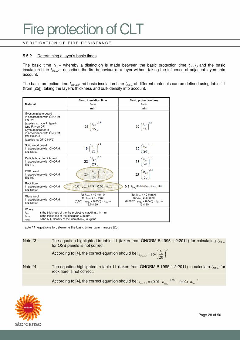
5.5.2 Determining a layer’s basic times The basic time t0,i – whereby a distinction is made between the basic protection time tprot,0,i and the basic insulation time tins,0,i – describes the fire behaviour of a layer without taking the influence of adjacent layers into account. The basic protection time tprot,0,i and basic insulation time tins,0,i of different materials can be defined using table 11 (from [25]), taking the layer’s thickness and bulk density into account.
Material Basic insulation time
tins,0,i Basic protection time
tins,0,i
min min
Gypsum plasterboard in accordance with ÖNORM EN 520 (applies to: type A, type H, type F, type DF) Gypsum fibreboard in accordance with ÖNORM EN 15283-2 (applies to: GF-C1-W2)
Solid wood board in accordance with ÖNORM EN 13353
Particle board (chipboard) in accordance with ÖNORM EN 312
OSB board in accordance with ÖNORM EN 300
Rock fibre in accordance with ÖNORM EN 13162
Glass wool in accordance with ÖNORM EN 13162
for hins,i < 40 mm: 0 for hins,i � 40 mm:
(0,001 · �ins,i + 0,035) · hins,i + 8,5 � 30
for hins,i < 40 mm: 0 for hins,i � 40 mm:
(0,0007 · �ins,i + 0,046) · hins,i + 13 � 30
Where: hp,i is the thickness of the fire protective cladding i, in mm hins,i is the thickness of the insulation i, in mm �ins,i is the bulk density of the insulation i, in kg/m³
Table 11: equations to determine the basic times t0,i in minutes [25] Note *3: The equation highlighted in table 11 (taken from ÖNORM B 1995-1-2:2011) for calculating tins,0,i
for OSB panels is not correct.
According to [4], the correct equation should be: 4,1
,0,20
16 ��
�A
B⋅= i
iins
ht
Note *4: The equation highlighted in table 11 (taken from ÖNORM B 1995-1-2:2011) to calculate tins,0,i for
rock fibre is not correct. According to [4], the correct equation should be: 2
,
224,0
,,0, )02,001,0( iinsiinsiins ht ⋅−⋅= ρ
*3
*4
�������������A��B�������������A��B�������������A��B�������������A��B����CDECDECDECDE���� ����
Page 29 of 50
V E R I F I C A T I O N O F F I R E R E S I S T A N C E
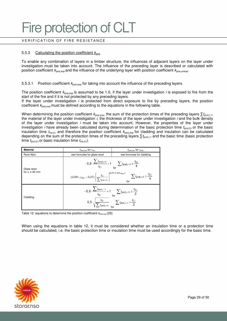
5.5.3 Calculating the position coefficient kpos
To enable any combination of layers in a timber structure, the influences of adjacent layers on the layer under investigation must be taken into account. The influence of the preceding layer is described or calculated with position coefficient kpos,exp and the influence of the underlying layer with position coefficient kpos,unexp. 5.5.3.1 Position coefficient kpos,exp for taking into account the influence of the preceding layers The position coefficient kpos,exp is assumed to be 1.0, if the layer under investigation i is exposed to fire from the start of the fire and if it is not protected by any preceding layers. If the layer under investigation i is protected from direct exposure to fire by preceding layers, the position coefficient kpos,exp must be defined according to the equations in the following table. When determining the position coefficient kpos,exp, the sum of the protection times of the preceding layers tprot,i-1, the material of the layer under investigation i, the thickness of the layer under investigation i and the bulk density of the layer under investigation i must be taken into account. However, the properties of the layer under investigation i have already been calculated during determination of the basic protection time tprot,0,i or the basic insulation time tins,0,i and therefore the position coefficient kpos,exp for cladding and insulation can be calculated depending on the sum of the protection times of the preceding layers tprot,i-1 and the basic time (basic protection time tprot,0,i or basic insulation time tins,0,i).
Material kpos,exp for tins,i kpos,exp for tprot,i
Rock fibre see formulae for glass wool see formulae for cladding
Glass wool for hi � 40 mm
for
for
Cladding for
for
Table 12: equations to determine the position coefficient kpos,exp [25] When using the equations in table 12, it must be considered whether an insulation time or a protection time should be calculated, i.e. the basic protection time or insulation time must be used accordingly for the basic time.
�������������A��B�������������A��B�������������A��B�������������A��B����CDECDECDECDE���� ����
Page 30 of 50
V E R I F I C A T I O N O F F I R E R E S I S T A N C E
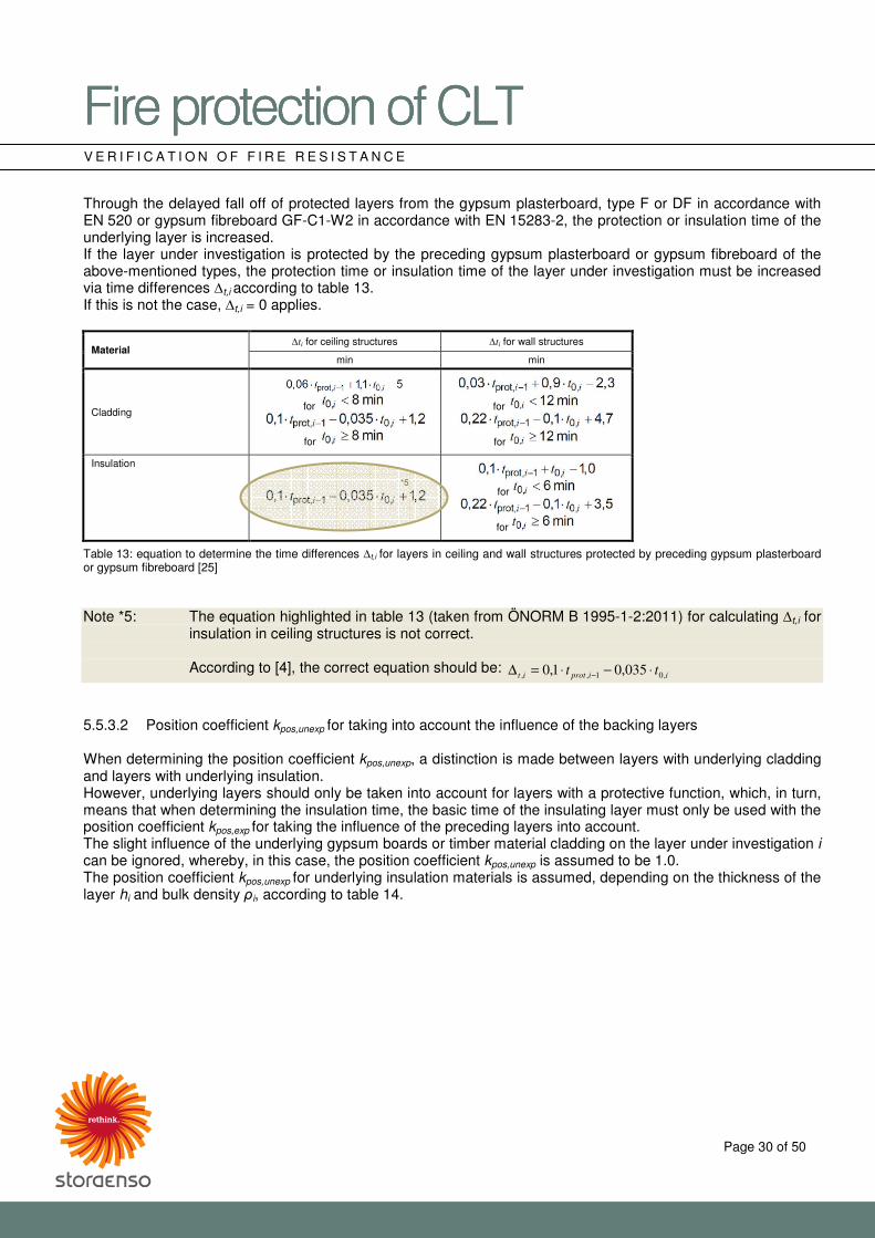
Through the delayed fall off of protected layers from the gypsum plasterboard, type F or DF in accordance with EN 520 or gypsum fibreboard GF-C1-W2 in accordance with EN 15283-2, the protection or insulation time of the underlying layer is increased. If the layer under investigation is protected by the preceding gypsum plasterboard or gypsum fibreboard of the above-mentioned types, the protection time or insulation time of the layer under investigation must be increased via time differences �t,i according to table 13. If this is not the case, �t,i = 0 applies.
Material �ti for ceiling structures �ti for wall structures
min min
Cladding
for
for
for
for
Insulation
for
for
Table 13: equation to determine the time differences �t,i for layers in ceiling and wall structures protected by preceding gypsum plasterboard or gypsum fibreboard [25] Note *5: The equation highlighted in table 13 (taken from ÖNORM B 1995-1-2:2011) for calculating �t,i for
insulation in ceiling structures is not correct. According to [4], the correct equation should be:
iiprotit tt ,01,, 035,01,0 ⋅−⋅=∆ −
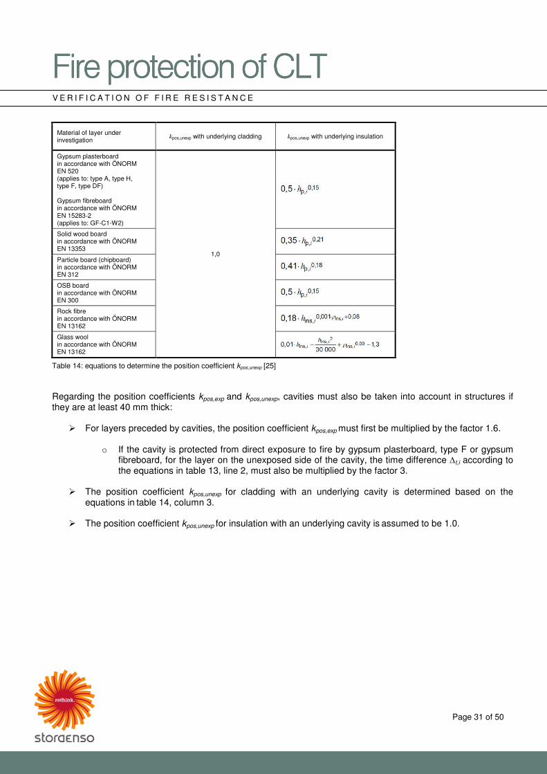
5.5.3.2 Position coefficient kpos,unexp for taking into account the influence of the backing layers When determining the position coefficient kpos,unexp, a distinction is made between layers with underlying cladding and layers with underlying insulation. However, underlying layers should only be taken into account for layers with a protective function, which, in turn, means that when determining the insulation time, the basic time of the insulating layer must only be used with the position coefficient kpos,exp for taking the influence of the preceding layers into account. The slight influence of the underlying gypsum boards or timber material cladding on the layer under investigation i can be ignored, whereby, in this case, the position coefficient kpos,unexp is assumed to be 1.0. The position coefficient kpos,unexp for underlying insulation materials is assumed, depending on the thickness of the layer hi and bulk density Ai, according to table 14.
*5
�������������A��B�������������A��B�������������A��B�������������A��B����CDECDECDECDE���� ����
Page 31 of 50
V E R I F I C A T I O N O F F I R E R E S I S T A N C E
Material of layer under investigation
kpos,unexp with underlying cladding kpos,unexp with underlying insulation
Gypsum plasterboard in accordance with ÖNORM EN 520 (applies to: type A, type H, type F, type DF) Gypsum fibreboard in accordance with ÖNORM EN 15283-2 (applies to: GF-C1-W2)
1,0
Solid wood board in accordance with ÖNORM EN 13353
Particle board (chipboard) in accordance with ÖNORM EN 312
OSB board in accordance with ÖNORM EN 300
Rock fibre in accordance with ÖNORM EN 13162
Glass wool in accordance with ÖNORM EN 13162
Table 14: equations to determine the position coefficient kpos,unexp [25] Regarding the position coefficients kpos,exp and kpos,unexp, cavities must also be taken into account in structures if they are at least 40 mm thick:
� For layers preceded by cavities, the position coefficient kpos,exp must first be multiplied by the factor 1.6.
o If the cavity is protected from direct exposure to fire by gypsum plasterboard, type F or gypsum fibreboard, for the layer on the unexposed side of the cavity, the time difference �t,i according to the equations in table 13, line 2, must also be multiplied by the factor 3.
� The position coefficient kpos,unexp for cladding with an underlying cavity is determined based on the
equations in table 14, column 3.
� The position coefficient kpos,unexp for insulation with an underlying cavity is assumed to be 1.0.
�������������A��B�������������A��B�������������A��B�������������A��B����CDECDECDECDE���� ����
Page 32 of 50
V E R I F I C A T I O N O F F I R E R E S I S T A N C E
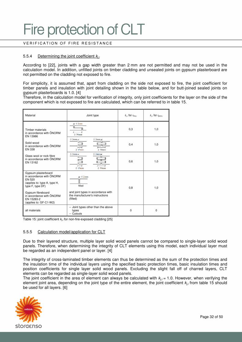
5.5.4 Determining the joint coefficient kj,i
According to [22], joints with a gap width greater than 2 mm are not permitted and may not be used in the calculation model. In addition, unfilled joints on timber cladding and unsealed joints on gypsum plasterboard are not permitted on the cladding not exposed to fire. For simplicity, it is assumed that, apart from cladding on the side not exposed to fire, the joint coefficient for timber panels and insulation with joint detailing shown in the table below, and for butt-joined sealed joints on gypsum plasterboards is 1.0. [4] Therefore, in the calculation model for verification of integrity, only joint coefficients for the layer on the side of the component which is not exposed to fire are calculated, which can be referred to in table 15.
Material Joint type kj,i for tins,i kj,i for tprot,i
Timber materials in accordance with ÖNORM EN 13986 Solid wood in accordance with ÖNORM EN 338 Glass wool or rock fibre in accordance with ÖNORM EN 13162
0,3 1,0
0,4 1,0
0,6 1,0
Gypsum plasterboard in accordance with ÖNORM EN 520 (applies to: type A, type H, type F, type DF) Gypsum fibreboard in accordance with ÖNORM EN 15283-2 (applies to: GF-C1-W2)
filled and joint types in accordance with the manufacturer's instructions (filled)
0,8 1,0
all materials – Joint types other than the above
types – Cutouts
0 0
Table 15: joint coefficient kj,i for non-fire-exposed cladding [25] 5.5.5 Calculation model/application for CLT
Due to their layered structure, multiple layer solid wood panels cannot be compared to single-layer solid wood panels. Therefore, when determining the integrity of CLT elements using this model, each individual layer must be regarded as an independent panel or layer. [4] The integrity of cross-laminated timber elements can thus be determined as the sum of the protection times and the insulation time of the individual layers using the specified basic protection times, basic insulation times and position coefficients for single layer solid wood panels. Excluding the slight fall off of charred layers, CLT elements can be regarded as single-layer solid wood panels. The joint coefficient in the area of element can always be calculated with kj,i = 1.0. However, when verifying the element joint area, depending on the joint type of the entire element, the joint coefficient kj,i from table 15 should be used for all layers. [6]
�������������A��B�CDE�������������A��B�CDE�������������A��B�CDE�������������A��B�CDE���� ����
Page 33 of 50
T E C H N I C A L F I R E P R O T E C T I O N O F D E T A I L I N G
6 Technical fire protection of detailing
6.1 Joints and connections between components
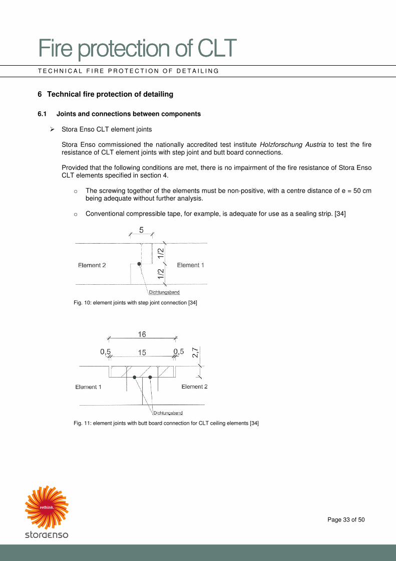
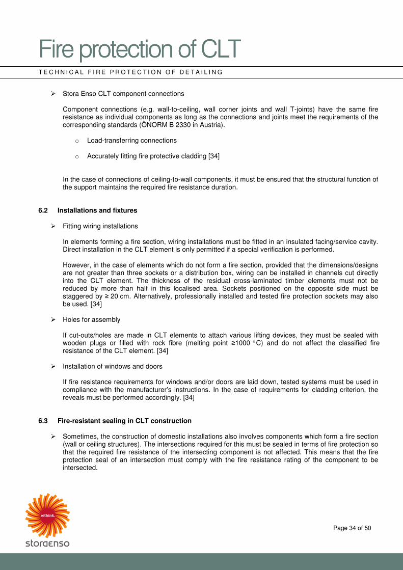
� Stora Enso CLT element joints
Stora Enso commissioned the nationally accredited test institute Holzforschung Austria to test the fire resistance of CLT element joints with step joint and butt board connections.
Provided that the following conditions are met, there is no impairment of the fire resistance of Stora Enso CLT elements specified in section 4.
o The screwing together of the elements must be non-positive, with a centre distance of e = 50 cm being adequate without further analysis.
o Conventional compressible tape, for example, is adequate for use as a sealing strip. [34]
Fig. 10: element joints with step joint connection [34]
Fig. 11: element joints with butt board connection for CLT ceiling elements [34]
�������������A��B�CDE�������������A��B�CDE�������������A��B�CDE�������������A��B�CDE���� ����
Page 34 of 50
T E C H N I C A L F I R E P R O T E C T I O N O F D E T A I L I N G
� Stora Enso CLT component connections
Component connections (e.g. wall-to-ceiling, wall corner joints and wall T-joints) have the same fire resistance as individual components as long as the connections and joints meet the requirements of the corresponding standards (ÖNORM B 2330 in Austria).
o Load-transferring connections
o Accurately fitting fire protective cladding [34]
In the case of connections of ceiling-to-wall components, it must be ensured that the structural function of the support maintains the required fire resistance duration.
6.2 Installations and fixtures
� Fitting wiring installations
In elements forming a fire section, wiring installations must be fitted in an insulated facing/service cavity. Direct installation in the CLT element is only permitted if a special verification is performed.
However, in the case of elements which do not form a fire section, provided that the dimensions/designs are not greater than three sockets or a distribution box, wiring can be installed in channels cut directly into the CLT element. The thickness of the residual cross-laminated timber elements must not be reduced by more than half in this localised area. Sockets positioned on the opposite side must be staggered by � 20 cm. Alternatively, professionally installed and tested fire protection sockets may also be used. [34]
� Holes for assembly
If cut-outs/holes are made in CLT elements to attach various lifting devices, they must be sealed with wooden plugs or filled with rock fibre (melting point �1000 °C) and do not affect the classified fire resistance of the CLT element. [34]
� Installation of windows and doors
If fire resistance requirements for windows and/or doors are laid down, tested systems must be used in compliance with the manufacturer’s instructions. In the case of requirements for cladding criterion, the reveals must be performed accordingly. [34]
6.3 Fire-resistant sealing in CLT construction
� Sometimes, the construction of domestic installations also involves components which form a fire section (wall or ceiling structures). The intersections required for this must be sealed in terms of fire protection so that the required fire resistance of the intersecting component is not affected. This means that the fire protection seal of an intersection must comply with the fire resistance rating of the component to be intersected.
�������������A��B�CDE�������������A��B�CDE�������������A��B�CDE�������������A��B�CDE���� ����
Page 35 of 50
T E C H N I C A L F I R E P R O T E C T I O N O F D E T A I L I N G
� The planning and implementation of seals usually involves several subsections. Corresponding
advanced planning is essential and indispensable for qualitative separation measures.
� For more information on the subject of “Fire-resistant sealing in timber structures”, Stora Enso refers the reader to [7]. Large-scale fire tests required for [7] for wall and ceiling components (respectively 90 minutes test duration) were performed using Stora Enso CLT elements. Detailed solutions for the installation, fastening and connection of various sealing systems for timber constructions have been developed on the basis of these test results and are explained in [7].
6.4 Fasteners
� To achieve a good fire protection joint, the steel component must accurately fit the timber structure. Steel
components which protrude past the surface of the wood should be avoided where possible. This reduces the transmission of heat released by the fire inside the timber cross-section.
� If greater fire resistance is required, fasteners can be fully protected by cladding made of wooden
materials or mineral panel materials.
� For further structural design information, Stora Enso refers the reader to [22], section 6. 6.5 Double-layered components
� Gaps between double-layered components must be fully insulated with rock fibre. [34] (In the fire situation, this can, for instance, prevent sparks or other burning components from falling between double-layered walls. In addition, by insulating the cavities, a possible chimney effect – which would favour the spread of fire – can be prevented.)
�������������A��B�CDE�������������A��B�CDE�������������A��B�CDE�������������A��B�CDE���� ����
Page 36 of 50
B I B L I O G R A P H Y
7 Bibliography
[1] PÖSCHL, W. (2004):
Zuschnitt 14 – Zeitschrift über Holz als Werkstoff und Werke in Holz [Magazine title: Wood as a material and works made of wood], proHolz Austria, Vienna
[2] FRANGI, A., FONTANA, M., HUGI, E., JÖBSTL, R. (2009):
Experimental analysis of cross-laminated timber panels in fire, Fire Safety Journal, Elsevier Ltd. [3] SCHEER, C., PETER, M. (2009):
Holz Brandschutz Handbuch [Wood fire protection guide], 3rd edition, Informationsdienst Holz [Timber Information Service], Deutsche Gesellschaft für Holzforschung e. V. (DGfH) [German Society for Wood Research], Munich
[4] SCHLEIFER, V. (2009):
Zum Verhalten von raumabschließenden mehrschichtigen Holzbauteilen im Brandfall [On the behaviour of separating multiple timber elements in the fire situation], thesis, Institut für Baustatik und Konstruktion [Institute of Structural Engineering], ETH Zürich [Swiss Federal Institute of Technology], Zurich
[5] TEIBINGER, M., MATZINGER, I. (2013):
Bauen mit Brettsperrholz im Geschoßbau – Focus Bauphysik, Planungsbroschüre, [Building with CLT in building constructions - Focus on building physics, planning guide], Holzforschung Austria, Vienna
[6] FRANGI, A., BRÜHWILER, I., STUDHALTER, J., WIEDERKEHR, R. (2011):
Lignum – Dokumentation Brandschutz – 3.1 Feuerwiderstandsbemessung – Bauteile und Verbindungen, 1. Auflage [Lignum – Fire protection documentation – 3.1 Fire resistance calculation – Components and connections, 1st edition], Lignum – Holzwirtschaft Schweiz [Swiss Wood Industry Federation], Zürich
[7] TEIBINGER, M., MATZINGER, I. (2012):
Brandabschottung im Holzbau, Planungsbroschüre [Fire-resistant sealing in timber structures, planning guide], ISBN 978-3-9503367-9, Holzforschung Austria, Vienna
[8] TEIBINGER, M., MATZINGER, I. (2010):
Grundlagen zur Bewertung des Feuerwiderstandes von Holzkonstruktionen Endbericht, [Principles of fire-resistance rating of timber structures. Final report.] Holzforschung Austria, Vienna
[9] ÖSTMAN, B. et al. (2010):
Fire safety in timber buildings – Technical guideline for Europe, SP Trätek, Stockholm
�������������A��B�CDE�������������A��B�CDE�������������A��B�CDE�������������A��B�CDE���� ����
Page 37 of 50
B I B L I O G R A P H Y Standards [10] EN 300:
Oriented strand board (OSB) – Definitions, classification and requirements
[11] EN 309:
Particle boards – Definition and classification [12] EN 338:
Load-bearing wood – Strength classes, 2009 edition [13] EN 520:
Gypsum plasterboard – Terms, requirements and test methods, 2009 edition
[14] EN 1365-1:
Fire resistance tests for load-bearing elements – Part 1: Walls, 2012 edition
[15] EN 1365-2:
Fire resistance tests for load-bearing elements – Part 2: Ceilings and roofs, 1999 edition [16] EN 1990:
Eurocode: Principles of structural design, 2002 edition [17] EN 1991-1-2:
Eurocode 1: Actions on structures – Part 1–2: General actions – Actions on structures exposed to fire, 2002 edition
[18] EN 13162
Insulation products for buildings – Factory made mineral wool (MW) products – Specification [19] EN 13501-1:
Fire classification of construction products and building elements – Part 1: Classification using data from reaction to fire tests, 2009 edition
[20] EN 13501-2:
Fire classification of construction products and building elements – Part 2: Classification using data from reaction to fire tests, excluding ventilation services, 2009 edition
[21] EN 15283-2:
Gypsum plasterboard – Terms, requirements and test methods – Part 2: Gypsum plasterboard [22] ÖNORM EN 1995-1-2:
Eurocode 5: Design of timber structures – Part 1–2: General – Structural fire design, 2011-09-01 edition
�������������A��B�CDE�������������A��B�CDE�������������A��B�CDE�������������A��B�CDE���� ����
Page 38 of 50
B I B L I O G R A P H Y [23] ÖNORM B 2330:
Technical fire protection of multiple storey wooden and prefabricated wooden houses – Requirements and examples for execution
[24] ÖNORM B 3410:
Gypsum plasterboard for dry wall systems (plasterboard) – Types, requirements and tests, 2006 edition [25] ÖNORM B 1995-1-2:
Eurocode 5: Design of timber structures – Part 1–2: General – Structural fire design – National specifications on ÖNORM EN 1995-1-2, national explanations and national supplements, 2011-09-01 edition
Approvals, classification reports and statements of expert opinion [26] DEUTSCHES INSTITUT FÜR BAUTECHNIK [GERMAN INSTITUTE FOR STRUCTURAL ENGINEERING] (2011):
European Technical Approval ETA-08/0271, CLT – Cross-Laminated Timber, German Institute for Structural Engineering, Berlin
[27] HOLZFORSCHUNG AUSTRIA (2011):
Classification report 1720/2011/01, classification report on the REI 60 fire resistance rating for load-bearing cross-laminated timber elements as “Stora Enso CLT 80 C3s” wall elements non-faced � 80 mm and faced with gypsum boards, Holzforschung Austria, Vienna
[28] HOLZFORSCHUNG AUSTRIA (2011):
Classification report 1720/2011/02, classification report on the REI 90 fire resistance rating for load-bearing cross-laminated timber elements as “Stora Enso CLT 80 C3s” wall elements non-faced � 80 mm and faced with gypsum boards, Holzforschung Austria, Vienna
[29] HOLZFORSCHUNG AUSTRIA (2011):
Classification report 1720/2011/03, classification report on the REI 120 fire resistance rating for load-bearing cross-laminated timber elements as “Stora Enso CLT 100 C3s” wall elements � 100 faced with gypsum boards, Holzforschung Austria, Vienna
[30] HOLZFORSCHUNG AUSTRIA (2011):
Classification report 1720/2011/04, classification report on the REI 60 fire resistance rating for load-bearing cross-laminated timber elements as “Stora Enso CLT 100 C3s” ceiling/roof elements � 100 mm faced with gypsum boards, Holzforschung Austria, Vienna
[31] HOLZFORSCHUNG AUSTRIA (2011):
Classification report 1720/2011/05, classification report on the REI 90/EI 90 fire resistance rating for load-bearing cross-laminated timber elements as “Stora Enso CLT 100 C3s” ceiling/roof elements � 140 mm faced with gypsum boards, Holzforschung Austria, Vienna
�������������A��B�CDE�������������A��B�CDE�������������A��B�CDE�������������A��B�CDE���� ����
Page 39 of 50
B I B L I O G R A P H Y
[32] HOLZFORSCHUNG AUSTRIA (2011):
Classification report 1720/2011/06, classification report on the REI 90 fire resistance rating of load-bearing cross-laminated timber elements as external walls, Holzforschung Austria, Vienna
[33] HOLZFORSCHUNG AUSTRIA (2011):
Statement of expert opinion 122/2011/02, Calculability of the load capacity and integrity of “Stora Enso CLT” cross-laminated timber components, Holzforschung Austria, Vienna
[34] HOLZFORSCHUNG AUSTRIA (2011):
Statement of expert opinion 122/2011/04, Evaluation of the fire resistance of Stora Enso CLT element joints, electrical installations, mounting holes for lifting systems and window and door cut-outs, Holzforschung Austria, Vienna
[35] HOLZFORSCHUNG AUSTRIA (2013):
Statement of expert opinion 2434/2012-BB, Expert opinion about the failure time tf of fire protection plasterboards (GKF) according to ÖNORM B 3410 or gypsum plasterboards, type DF according to EN 520: 1 × 12.5 mm and 2 × 15 mm, respectively, on CLT wall elements, Holzforschung Austria, Vienna
[36] HOLZFORSCHUNG AUSTRIA (2013):
Classification report 52/2013, classification report on the REI 90 fire resistance rating of load-bearing cross-laminated timber according to ÖNORM EN 13501-2, Holzforschung Austria, Vienna
�������������A��B�CDE�������������A��B�CDE�������������A��B�CDE�������������A��B�CDE���� ����
Page 40 of 50
A N N E X Annex 1 – Calculation examples A 1.1 Determining the charring rate of Stora Enso CLT (non-faced) Assumption: CLT 180 L5s (lamella structure: 40–30–40–30–40) as an unclad ceiling element; required fire
resistance duration: 90 minutes; Calculation: Fire resistance of the 1st layer:
min5.61min/65.0
0.40
0
==mm
mmd
β
Fire resistance of the 2nd layer:
min9.26min/65.0
0.5
min/3.1
0.25
0
=+=mm
mm
mm
mmd
β
Charring depth of the 3rd layer: mmmmtdchar 1.2min)9.26min5.61min0.90(min/3.101,0, =−−⋅=⋅= β
Charring depth design value: mmmmmmmmdchar 1.721.20.300.400, =++=
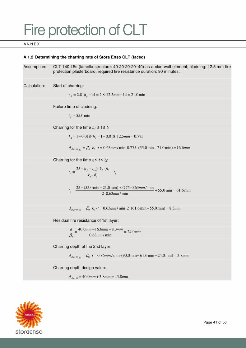
�������������A��B�CDE�������������A��B�CDE�������������A��B�CDE�������������A��B�CDE���� ����
Page 41 of 50
A N N E X A 1.2 Determining the charring rate of Stora Enso CLT (faced) Assumption: CLT 140 L5s (lamella structure: 40-20-20-20–40) as a clad wall element; cladding: 12.5 mm fire
protection plasterboard; required fire resistance duration: 90 minutes; Calculation: Start of charring: min0.21145.128.2148.2 =−⋅=−⋅= mmht pch
Failure time of cladding: min0.55=ft
Charring for the time tch � t � tf:
775.05.12018.01018.012 =⋅−=⋅−= mmhk p
mmmmtkd
achar 6.16min)0.21min0.55(775.0min/63.0202,0, =−⋅⋅=⋅⋅= β
Charring for the time tf � t � ta:
min6.61min0.55min/63.02
min/63.0775.0min)0.21min0.55(25
)(25
03
02
=+⋅
⋅⋅−−=
+⋅
⋅⋅−−=
mm
mmt
tk
kttt
a
f
chf
aβ
β
mmmmtkd
bchar 3.8min)0.55min6.61(2min/63.0302,0, =−⋅⋅=⋅⋅= β
Residual fire resistance of 1st layer:
min0.24min/63.0
3.86.160.40
0
=−−
=mm
mmmmmmd
β
Charring depth of the 2nd layer: mmmmtd
cchar 8.3min)0.24min6.61min0.90(min/86.002,0, =−−⋅=⋅= β
Charring depth design value: mmmmmmdchar 8.438.30.400, =+=
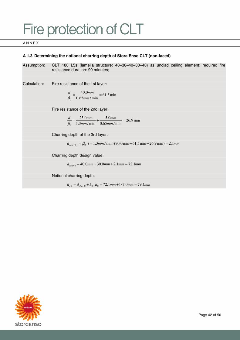
�������������A��B�CDE�������������A��B�CDE�������������A��B�CDE�������������A��B�CDE���� ����
Page 42 of 50
A N N E X A 1.3 Determining the notional charring depth of Stora Enso CLT (non-faced) Assumption: CLT 180 L5s (lamella structure: 40–30–40–30–40) as unclad ceiling element; required fire
resistance duration: 90 minutes; Calculation: Fire resistance of the 1st layer:
min5.61min/65.0
0.40
0
==mm
mmd
β
Fire resistance of the 2nd layer:
min9.26min/65.0
0.5
min/3.1
0.25
0
=+=mm
mm
mm
mmd
β
Charring depth of the 3rd layer: mmmmtdchar 1.2min)9.26min5.61min0.90(min/3.101,0, =−−⋅=⋅= β
Charring depth design value: mmmmmmmmdchar 1.721.20.300.400, =++=
Notional charring depth: mmmmmmdkdd charfe 1.790.711.72000, =⋅+=⋅+=
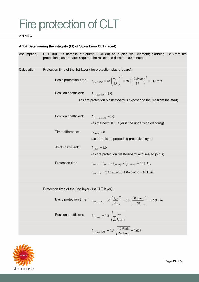
�������������A��B�CDE�������������A��B�CDE�������������A��B�CDE�������������A��B�CDE���� ����
Page 43 of 50
A N N E X A 1.4 Determining the integrity (EI) of Stora Enso CLT (faced) Assumption: CLT 100 L5s (lamella structure: 30-40-30) as a clad wall element; cladding: 12.5 mm fire
protection plasterboard; required fire resistance duration: 90 minutes; Calculation: Protection time of the 1st layer (fire protection plasterboard):
Basic protection time: min1.2415
5.1230
1530
2.12.1
,
,0, =��
�A
B⋅=��
�
�A
B⋅=
mmht
ip
GKFprot
Position coefficient: 0.1exp,, =GKFposk
(as fire protection plasterboard is exposed to the fire from the start) Position coefficient: 0.1exp,, =GKFunposk
(as the next CLT layer is the underlying cladding) Time difference: 0, =∆ GKFt
(as there is no preceding protective layer) Joint coefficient: 0.1, =GKFjk
(as fire protection plasterboard with sealed joints) Protection time:
ijiiunposiposiprotiprot ktkktt ,exp,,exp,,,0,, )( ⋅∆+⋅⋅=
min1.240.1)00.10.1min1.24(, =⋅+⋅⋅=GKFprott
Protection time of the 2nd layer (1st CLT layer):
Basic protection time: min9.4620
0.3030
2030
1.11.1
,
1,0, =��
�A
B⋅=��
�
�A
B⋅=
mmht
ip
CLTprot
Position coefficient: � −
⋅=1,
,0
,exp, 5.0iprot
i
ipost
tk
698.0min1.24
min9.465.01exp,, =⋅=CLTposk
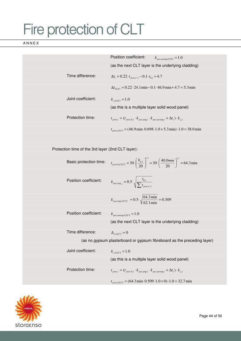
�������������A��B�CDE�������������A��B�CDE�������������A��B�CDE�������������A��B�CDE���� ����
Page 44 of 50
A N N E X Position coefficient: 0.11exp,, =CLTunposk
(as the next CLT layer is the underlying cladding) Time difference: 7.41.022.0 ,01, +⋅−⋅=∆ − iiproti ttt
min3.57.4min9.461.0min1.2422.01 =+⋅−⋅=∆ CLTt
Joint coefficient: 0.11, =CLTjk
(as this is a multiple layer solid wood panel) Protection time:
ijiiunposiposiprotiprot ktkktt ,exp,,exp,,,0,, )( ⋅∆+⋅⋅=
min0.380.1min)3.50.1698.0min9.46(1, =⋅+⋅⋅=CLTprott
Protection time of the 3rd layer (2nd CLT layer):
Basic protection time: min3.6420
0.4030
2030
1.11.1
,
2,0, =��
�A
B⋅=��
�
�A
B⋅=
mmht
ip
CLTprot
Position coefficient: � −
⋅=1,
,0
,exp, 5.0iprot
i
ipost
tk
509.0min1.62
min3.645.02exp,, =⋅=CLTposk
Position coefficient: 0.12exp,, =CLTunposk
(as the next CLT layer is the underlying cladding) Time difference: 02, =∆ CLTt
(as no gypsum plasterboard or gypsum fibreboard as the preceding layer) Joint coefficient: 0.12, =CLTjk
(as this is a multiple layer solid wood panel) Protection time:
ijiiunposiposiprotiprot ktkktt ,exp,,exp,,,0,, )( ⋅∆+⋅⋅=
min7.320.1)00.1509.0min3.64(2, =⋅+⋅⋅=CLTprott
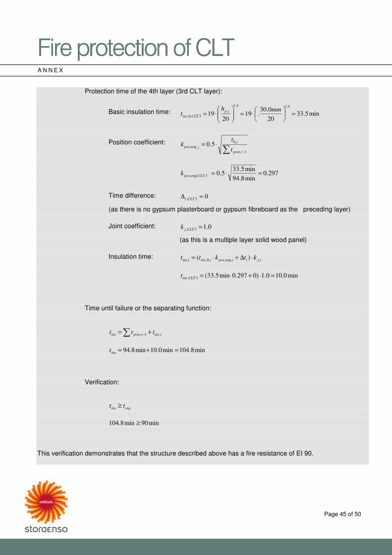
�������������A��B�CDE�������������A��B�CDE�������������A��B�CDE�������������A��B�CDE���� ����
Page 45 of 50
A N N E X
Protection time of the 4th layer (3rd CLT layer):
Basic insulation time: min5.3320
0.30.19
2019
4.14.1
,
3,0, =��
�A
B⋅=��
�
�A
B⋅=
mmht
ip
CLTins
Position coefficient: � −
⋅=1,
,0
,exp, 5.0iprot
i
ipost
tk
297.0min8.94
min5.335.03exp,, =⋅=CLTposk
Time difference: 03, =∆ CLTt
(as there is no gypsum plasterboard or gypsum fibreboard as the preceding layer) Joint coefficient: 0.13, =CLTjk
(as this is a multiple layer solid wood panel) Insulation time:
ijiiposiinsiins ktktt ,,exp,,0,, )( ⋅∆+⋅=
min0.100.1)0297.0min5.33(3, =⋅+⋅=CLTinst
Time until failure or the separating function: � += − iinsiprotins ttt ,1,
min8.104min0.10min8.94 =+=inst
Verification:
reqins tt ≥
min90min8.104 ≥
This verification demonstrates that the structure described above has a fire resistance of EI 90.
�������������A��B�CDE�������������A��B�CDE�������������A��B�CDE�������������A��B�CDE���� ����
Page 46 of 50
A N N E X Annex 2 – Information on the residual cross-section and integrity of Stora Enso CLT components The values specified and calculated in tables 16–20 are based on the following conditions: R criterion:
� The notional residual cross-section calculated (in millimetres) according to the CLT component and the required fire resistance are based on the charring rates confirmed by the statement of expert opinion for Stora Enso CLT in accordance with [33], the failure times confirmed by the statement of expert opinion for fire protection plasterboard cladding on Stora Enso CLT in accordance with [35] (for direct cladding), the failure times for fire protective cladding in accordance with [25] (for cladding with service cavities), the calculation according to [22] and the assumption of one-sided charring.
� During the mathematical determination of the notional residual cross-section, in addition to the charring depth, the zero-strength and stiffness layer k0 × d0 must also be taken into account. (According to [26] with regard to [22]: d0= 7 mm)
� Residual cross-sections of lamellas which are � 3 mm thick are not used in the remaining calculations. (Lamellas/layers concerned by this regulation are indicated with (1) in the following tables.)
� If the charring or char line is in a structurally non-load-bearing position, the residual strength of this position is shown in brackets. When determining the structural residual cross-section, this is taken into account or subtracted for the non-load-bearing lamellas/layers affected by exposure to fire.
� Lamellas/layers in the main load-bearing direction are shown in bold in the following tables.
EI criterion:
� Integrity calculated depending on the CLT component and the required fire resistance is determined according to [25] or [9] or [4]. The integrity values in the following tables concern the verification in the area of element. If the component under investigation is composed of several individual elements, the verification must also be performed in the area of element joints, whereby a different result is obtained due to the assumption of a corresponding joint coefficient.
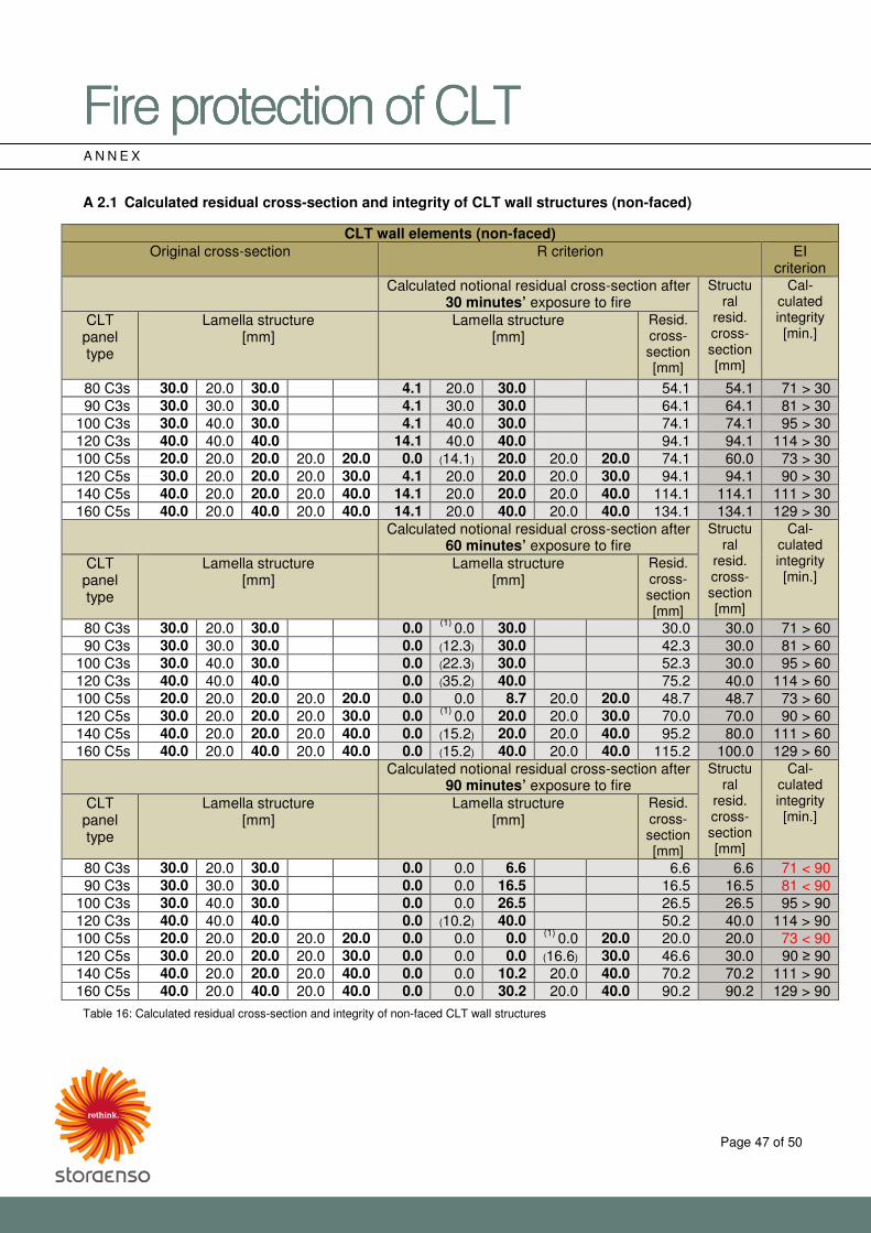
�������������A��B�CDE�������������A��B�CDE�������������A��B�CDE�������������A��B�CDE���� ����
Page 47 of 50
A N N E X A 2.1 Calculated residual cross-section and integrity of CLT wall structures (non-faced)
CLT wall elements (non-faced) Original cross-section R criterion EI
criterion Calculated notional residual cross-section after
30 minutes’ exposure to fire Structu
ral resid. cross-section [mm]
Cal-culated integrity [min.]
CLT panel type
Lamella structure [mm]
Lamella structure [mm]
Resid. cross-section [mm]
80 C3s 30.0 20.0 30.0 4.1 20.0 30.0 54.1 54.1 71 > 30 90 C3s 30.0 30.0 30.0 4.1 30.0 30.0 64.1 64.1 81 > 30
100 C3s 30.0 40.0 30.0 4.1 40.0 30.0 74.1 74.1 95 > 30 120 C3s 40.0 40.0 40.0 14.1 40.0 40.0 94.1 94.1 114 > 30 100 C5s 20.0 20.0 20.0 20.0 20.0 0.0 (14.1) 20.0 20.0 20.0 74.1 60.0 73 > 30 120 C5s 30.0 20.0 20.0 20.0 30.0 4.1 20.0 20.0 20.0 30.0 94.1 94.1 90 > 30 140 C5s 40.0 20.0 20.0 20.0 40.0 14.1 20.0 20.0 20.0 40.0 114.1 114.1 111 > 30 160 C5s 40.0 20.0 40.0 20.0 40.0 14.1 20.0 40.0 20.0 40.0 134.1 134.1 129 > 30
Calculated notional residual cross-section after 60 minutes’ exposure to fire
Structural
resid. cross-section [mm]
Cal-culated integrity [min.]
CLT panel type
Lamella structure [mm]
Lamella structure [mm]
Resid. cross-section [mm]
80 C3s 30.0 20.0 30.0 0.0 (1) 0.0 30.0 30.0 30.0 71 > 60 90 C3s 30.0 30.0 30.0 0.0 (12.3) 30.0 42.3 30.0 81 > 60
100 C3s 30.0 40.0 30.0 0.0 (22.3) 30.0 52.3 30.0 95 > 60 120 C3s 40.0 40.0 40.0 0.0 (35.2) 40.0 75.2 40.0 114 > 60 100 C5s 20.0 20.0 20.0 20.0 20.0 0.0 0.0 8.7 20.0 20.0 48.7 48.7 73 > 60 120 C5s 30.0 20.0 20.0 20.0 30.0 0.0 (1) 0.0 20.0 20.0 30.0 70.0 70.0 90 > 60 140 C5s 40.0 20.0 20.0 20.0 40.0 0.0 (15.2) 20.0 20.0 40.0 95.2 80.0 111 > 60 160 C5s 40.0 20.0 40.0 20.0 40.0 0.0 (15.2) 40.0 20.0 40.0 115.2 100.0 129 > 60
Calculated notional residual cross-section after 90 minutes’ exposure to fire
Structural
resid. cross-section [mm]
Cal-culated integrity [min.]
CLT panel type
Lamella structure [mm]
Lamella structure [mm]
Resid. cross-section [mm]
80 C3s 30.0 20.0 30.0 0.0 0.0 6.6 6.6 6.6 71 < 90 90 C3s 30.0 30.0 30.0 0.0 0.0 16.5 16.5 16.5 81 < 90
100 C3s 30.0 40.0 30.0 0.0 0.0 26.5 26.5 26.5 95 > 90 120 C3s 40.0 40.0 40.0 0.0 (10.2) 40.0 50.2 40.0 114 > 90 100 C5s 20.0 20.0 20.0 20.0 20.0 0.0 0.0 0.0 (1) 0.0 20.0 20.0 20.0 73 < 90 120 C5s 30.0 20.0 20.0 20.0 30.0 0.0 0.0 0.0 (16.6) 30.0 46.6 30.0 90 � 90 140 C5s 40.0 20.0 20.0 20.0 40.0 0.0 0.0 10.2 20.0 40.0 70.2 70.2 111 > 90 160 C5s 40.0 20.0 40.0 20.0 40.0 0.0 0.0 30.2 20.0 40.0 90.2 90.2 129 > 90
Table 16: Calculated residual cross-section and integrity of non-faced CLT wall structures
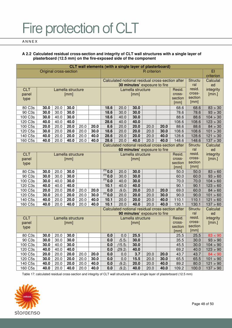
�������������A��B�CDE�������������A��B�CDE�������������A��B�CDE�������������A��B�CDE���� ����
Page 48 of 50
A N N E X A 2.2 Calculated residual cross-section and integrity of CLT wall structures with a single layer of
plasterboard (12.5 mm) on the fire-exposed side of the component
CLT wall elements (with a single layer of plasterboard) Original cross-section R criterion EI
criterion Calculated notional residual cross-section after
30 minutes’ exposure to fire Structu
ral resid. cross-section [mm]
Calculated
integrity [min.]
CLT panel type
Lamella structure [mm]
Lamella structure [mm]
Resid. cross-section [mm]
80 C3s 30.0 20.0 30.0 18.6 20.0 30.0 68.6 68.6 83 > 30 90 C3s 30.0 30.0 30.0 18.6 30.0 30.0 78.6 78.6 93 > 30
100 C3s 30.0 40.0 30.0 18.6 40.0 30.0 88.6 88.6 104 > 30 120 C3s 40.0 40.0 40.0 28.6 40.0 40.0 108.6 108.6 123 > 30 100 C5s 20.0 20.0 20.0 20.0 20.0 8.6 20.0 20.0 20.0 20.0 88.6 88.6 84 > 30 120 C5s 30.0 20.0 20.0 20.0 30.0 18.6 20.0 20.0 20.0 30.0 108.6 108.6 101 > 30 140 C5s 40.0 20.0 20.0 20.0 40.0 28.6 20.0 20.0 20.0 40.0 128.6 128.6 121 > 30 160 C5s 40.0 20.0 40.0 20.0 40.0 28.6 20.0 40.0 20.0 40.0 148.6 148.6 137 > 30
Calculated notional residual cross-section after 60 minutes’ exposure to fire
Structural
resid. cross-section [mm]
Calculated
integrity [min.]
CLT panel type
Lamella structure [mm]
Lamella structure [mm]
Resid. cross-section [mm]
80 C3s 30.0 20.0 30.0 (1) 0.0 20.0 30.0 50.0 50.0 83 > 60 90 C3s 30.0 30.0 30.0 (1) 0.0 30.0 30.0 60.0 60.0 93 > 60
100 C3s 30.0 40.0 30.0 (1) 0.0 40.0 30.0 70.0 70.0 104 > 60 120 C3s 40.0 40.0 40.0 10.1 40.0 40.0 90.1 90.1 123 > 60 100 C5s 20.0 20.0 20.0 20.0 20.0 0.0 (9.0) 20.0 20.0 20.0 69.0 60.0 84 > 60 120 C5s 30.0 20.0 20.0 20.0 30.0 (1) 0.0 20.0 20.0 20.0 30.0 90.0 90.0 101 > 60 140 C5s 40.0 20.0 20.0 20.0 40.0 10.1 20.0 20.0 20.0 40.0 110.1 110.1 121 > 60 160 C5s 40.0 20.0 40.0 20.0 40.0 10.1 20.0 40.0 20.0 40.0 130.1 130.1 137 > 60
Calculated notional residual cross-section after 90 minutes’ exposure to fire
Structural
resid. cross-section [mm]
Calculated
integrity [min.]
CLT panel type
Lamella structure [mm]
Lamella structure [mm]
Resid. cross-section [mm]
80 C3s 30.0 20.0 30.0 0.0 0.0 25.5 25.5 25.5 83 < 90 90 C3s 30.0 30.0 30.0 0.0 (5.5) 30.0 35.5 30.0 93 > 90
100 C3s 30.0 40.0 30.0 0.0 (15.5) 30.0 45.5 30.0 104 > 90 120 C3s 40.0 40.0 40.0 0.0 (29.2) 40.0 69.2 40.0 123 > 90 100 C5s 20.0 20.0 20.0 20.0 20.0 0.0 0.0 3.7 20.0 20.0 43.7 43.7 84 < 90 120 C5s 30.0 20.0 20.0 20.0 30.0 0.0 0.0 15.5 20.0 30.0 65.5 65.5 101 > 90 140 C5s 40.0 20.0 20.0 20.0 40.0 0.0 (9.2) 20.0 20.0 40.0 89.2 80.0 121 > 90 160 C5s 40.0 20.0 40.0 20.0 40.0 0.0 (9.2) 40.0 20.0 40.0 109.2 100.0 137 > 90
Table 17: calculated residual cross-section and integrity of CLT wall structures with a single layer of plasterboard (12.5 mm)
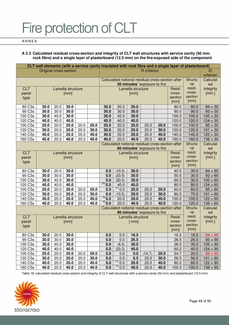
�������������A��B�CDE�������������A��B�CDE�������������A��B�CDE�������������A��B�CDE���� ����
Page 49 of 50
A N N E X A 2.3 Calculated residual cross-section and integrity of CLT wall structures with service cavity (50 mm.
rock fibre) and a single layer of plasterboard (12.5 mm) on the fire-exposed side of the component
CLT wall elements (with a service cavity insulated with rock fibre and a single layer of plasterboard) Original cross-section R criterion EI
criterion Calculated notional residual cross-section after
30 minutes’ exposure to fire Structu
ral resid. cross-section [mm]
Calculated
integrity [min.]
CLT panel type
Lamella structure [mm]
Lamella structure [mm]
Resid. cross-section [mm]
80 C3s 30.0 20.0 30.0 30.0 20.0 30.0 80.0 80.0 84 > 30 90 C3s 30.0 30.0 30.0 30.0 30.0 30.0 90.0 90.0 93 > 30
100 C3s 30.0 40.0 30.0 30.0 40.0 30.0 100.0 100.0 105 > 30 120 C3s 40.0 40.0 40.0 40.0 40.0 40.0 120.0 120.0 124 > 30 100 C5s 20.0 20.0 20.0 20.0 20.0 20.0 20.0 20.0 20.0 20.0 100.0 100.0 85 > 30 120 C5s 30.0 20.0 20.0 20.0 30.0 30.0 20.0 20.0 20.0 30.0 120.0 120.0 101 > 30 140 C5s 40.0 20.0 20.0 20.0 40.0 40.0 20.0 20.0 20.0 40.0 140.0 140.0 122 > 30 160 C5s 40.0 20.0 40.0 20.0 40.0 40.0 20.0 40.0 20.0 40.0 160.0 160.0 138 > 30
Calculated notional residual cross-section after 60 minutes’ exposure to fire
Structural
resid. cross-section [mm]
Calculated
integrity [min.]
CLT panel type
Lamella structure [mm]
Lamella structure [mm]
Resid. cross-section [mm]
80 C3s 30.0 20.0 30.0 0.0 (10.5) 30.0 40.5 30.0 84 > 60 90 C3s 30.0 30.0 30.0 0.0 (20.5) 30.0 50.5 30.0 93 > 60
100 C3s 30.0 40.0 30.0 0.0 (30.5) 30.0 60.5 30.0 105 > 60 120 C3s 40.0 40.0 40.0 (1) 0.0 40.0 40.0 80.0 80.0 124 > 60 100 C5s 20.0 20.0 20.0 20.0 20.0 0.0 (1) 0.0 20.0 20.0 20.0 60.0 60.0 85 > 60 120 C5s 30.0 20.0 20.0 20.0 30.0 0.0 (10.5) 20.0 20.0 30.0 80.5 70.0 101 > 60 140 C5s 40.0 20.0 20.0 20.0 40.0 1) 0.0 20.0 20.0 20.0 40.0 100.0 100.0 122 > 60 160 C5s 40.0 20.0 40.0 20.0 40.0 1) 0.0 20.0 40.0 20.0 40.0 120.0 120.0 138 > 60
Calculated notional residual cross-section after 90 minutes’ exposure to fire
Structural
resid. cross-section [mm]
Calculated
integrity [min.]
CLT panel type
Lamella structure [mm]
Lamella structure [.mm]
Resid. cross-section [mm]
80 C3s 30.0 20.0 30.0 0.0 0.0 16.5 16.5 16.5 84 < 90 90 C3s 30.0 30.0 30.0 0.0 0.0 26.5 26.5 26.5 93 > 90
100 C3s 30.0 40.0 30.0 0.0 (6.5) 30.0 36.5 30.0 105 > 90 120 C3s 40.0 40.0 40.0 0.0 (20.2) 40.0 60.2 40.0 124 > 90 100 C5s 20.0 20.0 20.0 20.0 20.0 0.0 0.0 0.0 (14.7) 20.0 34.7 20.0 85 < 90 120 C5s 30.0 20.0 20.0 20.0 30.0 0.0 0.0 6.5 20.0 30.0 56.5 56.5 101 > 90 140 C5s 40.0 20.0 20.0 20.0 40.0 0.0 (1) 0.0 20.0 20.0 40.0 80.0 80.0 122 > 90 160 C5s 40.0 20.0 40.0 20.0 40.0 0.0 (1) 0.0 40.0 20.0 40.0 100.0 100.0 138 > 90
Table 18: calculated residual cross-section and integrity of CLT wall structures with a service cavity (50 mm) and plasterboard (12.5 mm)
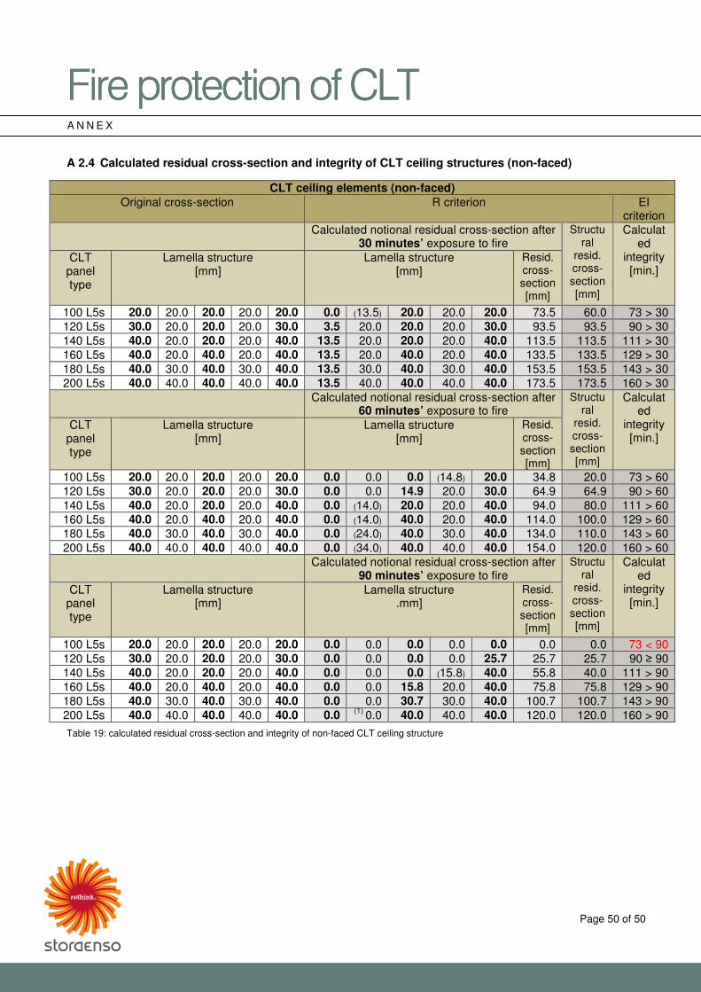
�������������A��B�CDE�������������A��B�CDE�������������A��B�CDE�������������A��B�CDE���� ����
Page 50 of 50
A N N E X A 2.4 Calculated residual cross-section and integrity of CLT ceiling structures (non-faced)
CLT ceiling elements (non-faced) Original cross-section R criterion EI
criterion Calculated notional residual cross-section after
30 minutes’ exposure to fire Structu
ral resid. cross-section [mm]
Calculated
integrity [min.]
CLT panel type
Lamella structure [mm]
Lamella structure [mm]
Resid. cross-section [mm]
100 L5s 20.0 20.0 20.0 20.0 20.0 0.0 (13.5) 20.0 20.0 20.0 73.5 60.0 73 > 30 120 L5s 30.0 20.0 20.0 20.0 30.0 3.5 20.0 20.0 20.0 30.0 93.5 93.5 90 > 30 140 L5s 40.0 20.0 20.0 20.0 40.0 13.5 20.0 20.0 20.0 40.0 113.5 113.5 111 > 30 160 L5s 40.0 20.0 40.0 20.0 40.0 13.5 20.0 40.0 20.0 40.0 133.5 133.5 129 > 30 180 L5s 40.0 30.0 40.0 30.0 40.0 13.5 30.0 40.0 30.0 40.0 153.5 153.5 143 > 30 200 L5s 40.0 40.0 40.0 40.0 40.0 13.5 40.0 40.0 40.0 40.0 173.5 173.5 160 > 30
Calculated notional residual cross-section after 60 minutes’ exposure to fire
Structural
resid. cross-section [mm]
Calculated
integrity [min.]
CLT panel type
Lamella structure [mm]
Lamella structure [mm]
Resid. cross-section [mm]
100 L5s 20.0 20.0 20.0 20.0 20.0 0.0 0.0 0.0 (14.8) 20.0 34.8 20.0 73 > 60 120 L5s 30.0 20.0 20.0 20.0 30.0 0.0 0.0 14.9 20.0 30.0 64.9 64.9 90 > 60 140 L5s 40.0 20.0 20.0 20.0 40.0 0.0 (14.0) 20.0 20.0 40.0 94.0 80.0 111 > 60 160 L5s 40.0 20.0 40.0 20.0 40.0 0.0 (14.0) 40.0 20.0 40.0 114.0 100.0 129 > 60 180 L5s 40.0 30.0 40.0 30.0 40.0 0.0 (24.0) 40.0 30.0 40.0 134.0 110.0 143 > 60 200 L5s 40.0 40.0 40.0 40.0 40.0 0.0 (34.0) 40.0 40.0 40.0 154.0 120.0 160 > 60
Calculated notional residual cross-section after 90 minutes’ exposure to fire
Structural
resid. cross-section [mm]
Calculated
integrity [min.]
CLT panel type
Lamella structure [mm]
Lamella structure .mm]
Resid. cross-section [mm]
100 L5s 20.0 20.0 20.0 20.0 20.0 0.0 0.0 0.0 0.0 0.0 0.0 0.0 73 < 90 120 L5s 30.0 20.0 20.0 20.0 30.0 0.0 0.0 0.0 0.0 25.7 25.7 25.7 90 � 90 140 L5s 40.0 20.0 20.0 20.0 40.0 0.0 0.0 0.0 (15.8) 40.0 55.8 40.0 111 > 90 160 L5s 40.0 20.0 40.0 20.0 40.0 0.0 0.0 15.8 20.0 40.0 75.8 75.8 129 > 90 180 L5s 40.0 30.0 40.0 30.0 40.0 0.0 0.0 30.7 30.0 40.0 100.7 100.7 143 > 90 200 L5s 40.0 40.0 40.0 40.0 40.0 0.0 (1) 0.0 40.0 40.0 40.0 120.0 120.0 160 > 90
Table 19: calculated residual cross-section and integrity of non-faced CLT ceiling structure