Embed Size (px)
Citation preview
7/28/2019 Stone Buildings
http://slidepdf.com/reader/full/stone-buildings 1/5
1
STONE BUILDINGS
Chapter 5
STONE BUILDINGS
5.1 INTRODUCTIONStone buildings using fully dressed
rectangularized stone units, or cast solid
blocks consisting of large stone pieces in
cement concrete mix 1:3.6 may be built ac-
cording to the details given in Chapter 4.
Those also generally apply to the random-
rubble and half -dressed stone buildings
except such details as are dealt with in this
Chapter.
5.2 TYPICAL DAMAGE ANDFAILURE OF STONE
Buildings Random rubble and half -
dressed stone buildings, Fig 5.l, have suf-
fered extensive damage and complete col-
lapse during past earthquakes having in-
tensifies of MSK VII and more.
The following are the main ways in
which such buildings are seen to be dam-aged :
Separation of walls at corners and
T-junctions takes place even more
easily than in brick buildings due to
poorer connection between the
walls.
Delamination and bulging of walls,that is, vertical separation of inter-
nal wythe and external wythe
through the middle of wall thickness,
Fig5.2. This occurs due mainly to the
absence of through or bond stones
and weak mortar filling between the
wythes. In half-dressed stone ma-
sonry, the surface stones are pyrami-
dal in shape having more or less an
edge contact one over the other, thusthe stones have an unstable equilib-
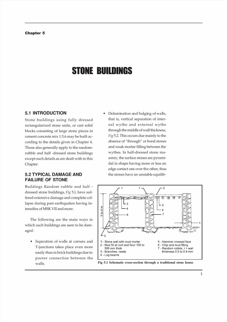
Fig 5.1 Schematic cross-section through a traditional stone house

7/28/2019 Stone Buildings
http://slidepdf.com/reader/full/stone-buildings 2/5
2
IAEE MANUAL
rium and easily disturbed under
shaking condition.
Crumbling and collapsing of bulged
wythes after delamination underheavy weight of roofs/ floors, lead-
ing to collapse of roof along with
walls or causing large gaps in walls.
Outward overturning of stone walls
after separation at corners due to in-
ertia of roofs and floors and their
own inertia when the roofs were in-
capable of acting as horizontal dia-
phragms. This particularly hap-
pened when the roof consisted of round poles, reed matting and clay
covering.
Frequently, such stone houses, under
MSK VII or higher intensifies, are completely
shattered and razed to the ground, the
walls reduced to only heaps of rubble. Peo-
ple get buried and more often killed. Thus
such buildings, without the seismic im-
provements as suggested here below, can
be considered as dangerous particularly in
seismic zones defined by Zones A and B in
Chapter 3.
5.3 TYPICAL STRUCTURALPROPERTIES
Test data on the strength characteristics of
random rubble and half-dressed stone ma-
sonry is not available. It is, however, quali-
tatively known that the compressive
strength even while using clay mud as
mortar will be enough to support three sto-
reys but the tensile strength could only be
near about zero. Sliding shear strength will
only be due to frictional resistance.
5.4 GENERAL CONSTRUCTIONASPECTS
5.4.1 Overall dimensions The height of the construction may
be restricted to one storey of category
I and II buildings and two storeys of
categories III and IV buildings.
Where light sheeted roof is used, an
attic floor may also be used.
The height of a storey may be kept as
low as 2.5 m but not more than 3.5
m.
The wall thickness should be used
as small as feasible, say 300 to 450
mm.
The unsupported length of a wall
between cross walls may be limited
to 7 m.Fig 5.3 Recommended openings in bearing walls in rubble masonry
Fig 5.2 Wall delaminated with buckled wythes
7/28/2019 Stone Buildings
http://slidepdf.com/reader/full/stone-buildings 3/5
3
STONE BUILDINGS
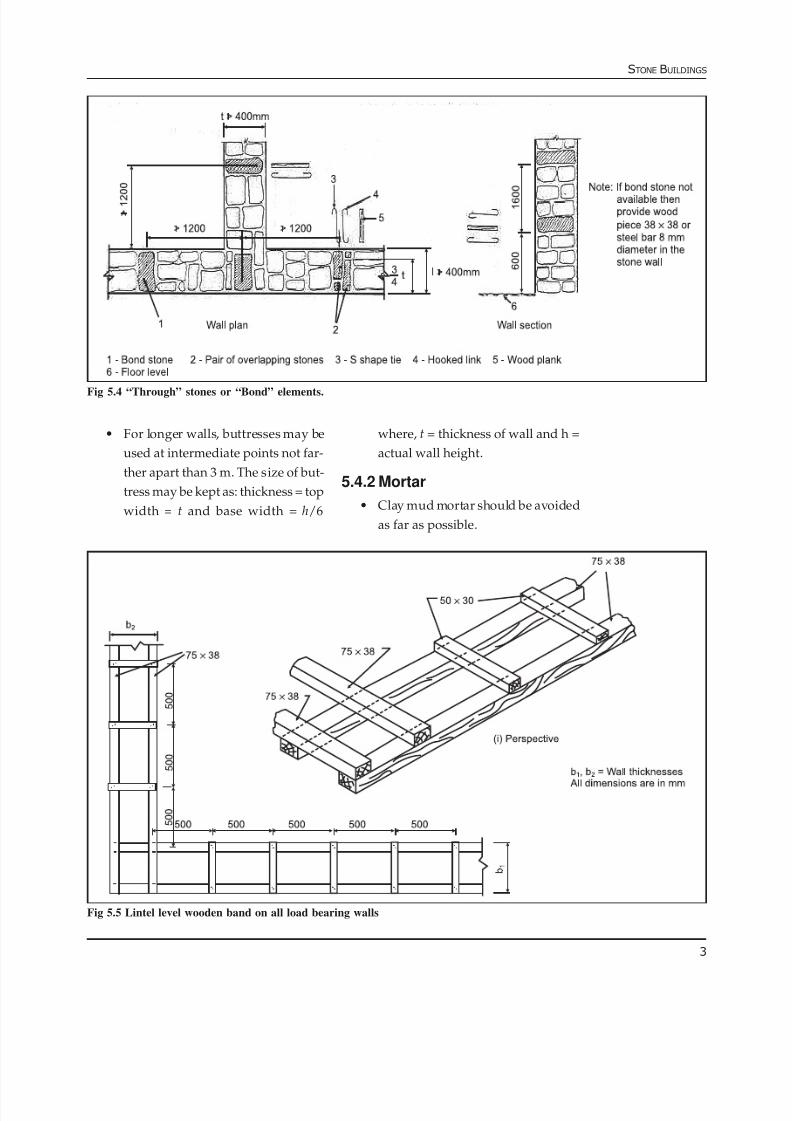
For longer walls, buttresses may be
used at intermediate points not far-
ther apart than 3 m. The size of but-
tress may be kept as: thickness = top
width = t and base width = h/6
where, t = thickness of wall and h =
actual wall height.
5.4.2 Mortar
Clay mud mortar should be avoided
as far as possible.
Fig 5.4 “Through” stones or “Bond” elements.
Fig 5.5 Lintel level wooden band on all load bearing walls

7/28/2019 Stone Buildings
http://slidepdf.com/reader/full/stone-buildings 4/5
4
IAEE MANUAL
Mortars as specified in Table 4.4 may
be used for stone walls.
5.4.3 Openings in walls
Openings should be as small and as
centrally located as practicable.
The recommended opening limita-
tions are shown in Fig 5.3.
Ventilator, where used, may be made
450 x 450 mm or smaller.
5.4.4 Masonry bond
Random rubble masonry construc-
tion should be brought to courses at
not more than 600 mm lift.
Through stones of full length
equal to wall thickness should be
used in every 600 mm lift at not more
than 1.2 m apart horizontally. If full
length stones are not available,
stones in pairs, each of about 3/4 of
the wall thickness may be used in
place of one full length stone so as to
provide an overlap between them,
Fig 5.4.
In place of through stones, bond-
ing elements of steel bars 8 to 10 mm
φ in S-shape or as a hooked link may
be used with a cover of 25 mm fromeach face of the wall, Fig 5.4.
Alternatively, wood bars of 38 mm x
38 mm cross-section or equivalent
may be used for the through
stones. Wood should be well pre-
served through seasoning and
Fig 5.6 Details of wood reinforcing at corners and T-junctions
Fig 5.7 Vertical steel in random rubble masonry
7/28/2019 Stone Buildings
http://slidepdf.com/reader/full/stone-buildings 5/5
5
STONE BUILDINGS
chemical treatment so as to be dura-
ble against weathering action and
insect attack, Fig 5.4.
Use of long stones should also be
made at corners and junction of wallsto break the vertical joint and pro-
vide bonding between perpendicu-
lar walls.
5.4.5 Horizontal reinforcing ofwalls
All the horizontal reinforcing recom-
mended for brick buildings in Section 4.5.1,
4.5.2 and 4.5.3 may be use for random rub-
ble constructions as well.
As an alternative to steel reinforcing
bars, wooden planks of rectangular section,
effectively spliced longitudinally and held
by lateral members in lattice form may be
used where timber is available and also
more economical. Recommended sections
are shown in Fig 5.5 and Fig 5.6
5.4.6 Vertical reinforcing of walls
The amount of vertical steel in masonry
walls required to be provided at the cor-
ners and T-junctions of walls and at jambs
of openings is shown in Table 5.1.
Buildings of Category IV need not have
the vertical steel at all. For providing verti-
cal bar in stone masonry a casing pipe is
recommended around which the masonry
is built to heights of 600 mm, Fig 5.7. The
pipe is kept loose by rotating it during ma-
sonry construction. Then the casing pipe is
raised and the cavity below is filled with
1:2:4 concrete mix and rodded to compact
it. The concrete will not only provide the
bond between the bar and the masonry but
will also protect the bar from corrosion.
The jamb steel may be taken from thefooting upto the lintel band and anchored
into it. The corner steel must be taken from
the footing upto the roof slab or roof band
and anchored into it.
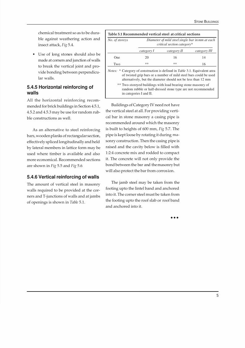
Table 5.1 Recommended vertical steel at critical sections
No. of storeys Diameter of mild steel single bar in mm at each
critical section category*
category I category II category III
One 20 16 14
Two ** ** 16
Notes: * Category of construction is defined in Table 3.1. Equivalent area
of twisted grip bars or a number of mild steel bars could be used
alternatively, but the diameter should not be less than 12 mm
** Two-storeyed buildings with load bearing stone masonry of
random rubble or half-dressed stone type are not recommended
in categories I and II.


![Study of the Productive Chain of Stone Facings in ... · Study of the Productive Chain of Stone Facings in Contemporary Buildings in São Paulo, ... 15846 [4] l mortar, glu ... s](https://img.pdfslide.us/doc/110x75/5b41a37d7f8b9a472b8b4ae6/study-of-the-productive-chain-of-stone-facings-in-study-of-the-productive.jpg)