Embed Size (px)
Citation preview
\ /T A mT7 T7 r? TV 17 TrSlTnNv^ W
—
<5 E © KB VJLULk WU,\
*
EACH NUMBER IS A UNIT IN A SERIES ON ELECTRICAL AND STEAM ENGINEERING DRAWING AND MACHINE DESIGN AND SHOP PRACTICE
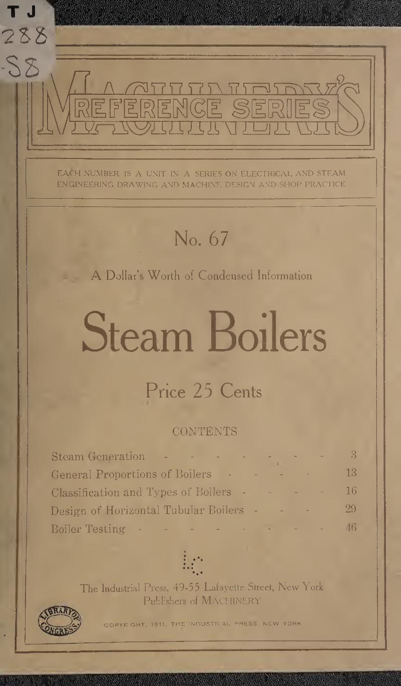
No. 67
A Dollar’s Worth of Condensed Information
Steam Boilers Price 25 Cents
CONTENTS
Steam Generation ------- 3
General Proportions of Boilers - 13
Classification and Types of Boilers 16
Design of Horizontal Tabular Boilers - 29
Boiler Testing.46
9
: o • • • •
•••
The Industrial Press, 49-55 Lafayette Street, New York
Publishers of MACHINERY
COPYRIGHT. 1911, THE INDUSTRIAL PRESS. NEW YORK
C0FYKIG1IT DEPOSIT.


%
. I
MACHINERY’S REFERENCE SERIES
EACH NUMBER IS A UNIT I SI A SERIES ON ELECTRICAL AND STEAM ENGINEERING
DRAWING AND MACHINE DESIGN AND SHOP PRACTICE
NUMBER 67
STEAM BOILERS
CONTENTS
Steam Generation. 3
General Proportions of Boilers - - - 13
Classification and Types of Boilers 16
Design of Horizontal Tubular Boilers - 29
Boiler Testing.46
Copyright, 1911, The Industrial Press, Publishers of Machinebi,
49-55 Lafayette Street, New York City

£ CLA280987
CHAPTER I
STEAM GENERATION
- Heat is recognized by the bodily sensation which it produces. Some
objects feel hot and others cold, according to the relative amount of
heat which they contain. Heat is supposed to be due to the vibration
of the molecules of a substance, and the intensity of the heat, or the
temperature, varies with the velocity and extent of these vibrations.
Temperature is measured in degrees. In the Fahrenheit (F.) scale,
which is commonly used in this country, the bulb of the thermometer
is first placed in the water from melting ice, and then in steam which
is being evaporated under atmospheric pressure, and the height to
which the mercury rises divided into 180 degrees. The temperature of
melting ice, or the freezing point, as it is called, is marked 32 degrees
above zero, which makes the boiling point temperature 32 -f 180 = 212
degrees above zero. In the Celsius system, the Centigrade (C.) scale
is used. In this case, the freezing point is marked 0, and the boiling
point, 100 degrees. The methods of conversion from one scale to the other are indicated by the following equations:
F= (1.8 X C) + 32,
C = 5/9 X (F — 32), in which,
C — reading on Centigrade scale,
F — reading on Fahrenheit scale.
Heat Unit and Latent Heat
The measure or unit of heat is the quantity required to raise the
temperature of 1 pound of water 1 degree, at its point of greatest
density. Although this occurs at about 39 degrees F., it is customary,
in ordinary computations, to disregard the temperature, and to define
a heat unit or thermal unit (T. U.) as simply the quantity of heat
required to raise the temperature of 1 pound of water 1 degree.
Latent heat is the heat which disappears when a solid is changed
to a liquid, or a liquid to a gas, the former being called the latent
heat of fusion, and the latter, the latent heat of evaporation. The heat
which disappears in this manner is converted into mechanical work,
and is used in tearing apart the molecules, and hence, produces no
change in the temperature of the substance. When the gas changes
pack to a liquid, or the liquid to a solid, the latent heat is again given
out. The action described may be illustrated by the melting of ice
into water, and the evaporation of the water into steam. When heat
is applied to a piece of ice in an open vessel, it gradually melts, but
the temperature of the water remains at 32 degrees until all of the ice
has been melted, the heat having been used in the process of cha'ng-
4 No. 67—BOILERS
ing the ice into water. If heat is still applied, the temperature of the
water will rise until it reaches 212 degrees, at which point evapora¬
tion takes place, and although heat is constantly applied, the tempera¬
ture of the water remains constant until it is all evaporated into steam.
If the steam were collected and condensed, and the water cooled to 32
degrees and frozen, all of the heat which had been supplied would
again be given out. Latent heat plays an important part in the oper¬
ation of a boiler and the generation of steam.
Convection, Conduction and Radiation
The currents set up within a liquid, due to temperature differences
in different parts, are called convection currents, and are important in
causing the water to circulate over the heating surfaces within a
steam boiler. The passage of heat from one body to another, or from
one part of the same body to another part at a lower temperature, is
called conduction. Heat from the furnace reaches the water within
a boiler by conduction through the plates, and is diffused throughout
the entire volume by the same process, assisted by convection. Heat
which is transmitted through the air by the vibration of the surround¬
ing ether is called radiant heat. This does not warm the air di¬
rectly, but is absorbed by the objects in its path, which in turn give
it up to the air by conduction. Much of the heat absorbed by the
plates directly above the fire in a boiler is radiant heat.
Steam
Steam is water changed to a gaseous form by the application of heat.
It may be saturated, superheated, dry, or wet. Saturated steam is that which is in the presence of, and at the same temperature as, the water
from which it was evaporated. There is always a definite relation
between the pressure and temperature in the case of saturated steam.
For example, saturated steam evaporated under atmospheric pressure
always has a temperature of 212 degrees. Steam evaporated under
a pressure of 5.3 pounds (gage) has a temperature of 227.9 degrees
F.; under 10.3 pounds pressure, 240 degrees F.; under 100.3 pounds,
337.8 degrees F., and so on.
Superheated steam is that which has been heated to a temperature
above that due to its pressure. Steam is superheated by passing it
through pipes or coils exposed to the hot gases from the furnace,
after it leaves the steam space of the boiler. Certain types of engines
and turbines are more efficient when supplied with superheated steam,
for reasons which cannot here be explained. Dry steam is that which
contains no moisture. It may be either saturated or superheated.
Wet steam, so called, contains more or less moisture in the form of
spray; in other ways it does not differ from saturated steam, having
the same temperature at different pressures.
The percentage of dry steam in steam containing moisture, is called
the quality of the steam. For example, if a pound of a given sample
of steam contains 0.04 of a pound of water in the form of spray, and
0.96 of a pound of dry saturated steam, the quality is said to be 96
STEAM GENERATION
Per cent. It is very important to know the quality of the steam when
testing a boiler for capacity and fuel consumption, as water carried
over in the form of spray has no value for the generation of power
in a steam engine, or for heating purposes. As the quantity of steam
evaporated in a given time is found by weighing the feed water, it is
evident that the moisture contained in the steam will appear in the
result, unless its percentage is known and the necessary correction
made. The proportion of moisture in steam is found by means of a
device called a calorimeter, which forms an important part of the equipment used in boiler testing.
The carrying over of moisture with the steam is commonly called
priming. This may be caused by impure water, too high a water-line,
the presence of oil, or of certain alkalis used in the removal of scale.
Priming may also be caused by forcing a boiler beyond the capacity
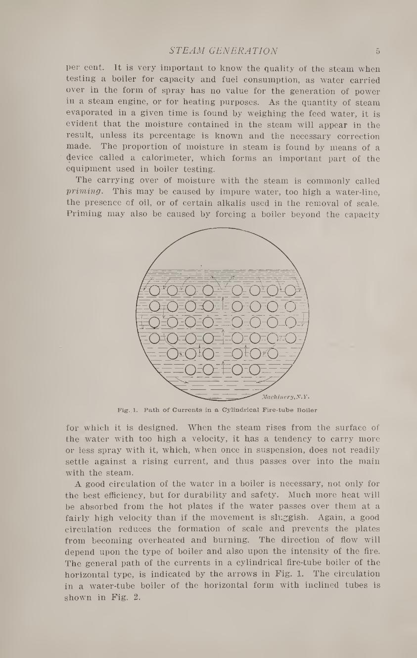
Fig. 1. Path of Currents in a Cylindrical Fire-tube Boiler
for which it is designed. When the steam rises from the surface of
the water with too high a velocity, it has a tendency to carry more
or less spray with it, which, when once in suspension, does not readily
settle against a rising current, and thus passes over into the main
with the steam.
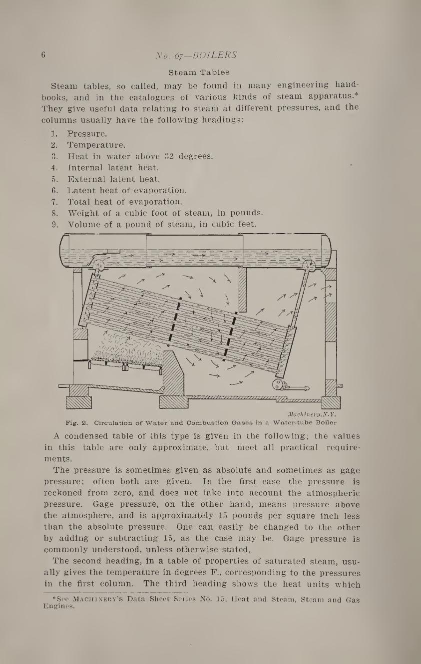
A good circulation of the water in a boiler is necessary, not only for
the best efficiency, but for durability and safety. Much more heat will
be absorbed from the hot plates if the water passes over them at a
fairly high velocity than if the movement is sluggish. Again, a good
circulation reduces the formation of scale and prevents the plates
from becoming overheated and burning. The direction of flow will
depend upon the type of boiler and also upon the intensity of the fire.
The general path of the currents in a cylindrical fire-tube boiler of the
horizontal type, is indicated by the arrows in Fig. 1. The circulation
in a water-tube boiler of the horizontal form with inclined tubes is
shown in Fig. 2.
6 No. 67—BOILERS
Steam Tables
Steam tables, so called, may be found in many engineering hand¬
books, and in the catalogues of various kinds of steam apparatus.*
They give useful data relating to steam at different pressures, and the
columns usually have the following headings:
1. Pressure.
2. Temperature.
3. Heat in water above 32 degrees.
4. Internal latent heat.
5. External latent heat.
6. Latent heat of evaporation.
7. Total heat of evaporation.
8. Weight of a cubic foot of steam, in pounds.
9. Volume of a pound of steam, in cubic feet.
Fig. 2. Circulation of Water and Combustion Gases in a Water-tube Boiler
A condensed table of this type is given in the following; the values
in this table are only approximate, but meet all practical require¬
ments.
The pressure is sometimes given as absolute and sometimes as gage
pressure; often both are given. In the first case the pressure is
reckoned from zero, and does not take into account the atmospheric
pressure. Gage pressure, on the other hand, means pressure above
the atmosphere, and is approximately 15 pounds per square inch less
than the absolute pressure. One can easily be changed to the other
by adding or subtracting 15, as the case may be. Gage pressure is
commonly understood, unless otherwise stated.
The second heading, in a table of properties of saturated steam, usu¬
ally gives the temperature in degrees F., corresponding to the pressures
in the first column. The third heading shows the heat units which
*See Machinery's Data Sheet Series No. 15, Heat and Steam, Steam and Gas Engines.
STEAM GENERATION 7
are required for raising the temperature of one pound of water
from 32 degrees to the evaporating point under the given pressure.
This value is practically the same as the number of degrees rise in tem¬
perature. The internal latent heat, usually given in the fourth column
of a complete steam table, represents the heat required in the work of
changing the water into steam, that is, in the process of evaporation.
The fifth column gives external latent heat, or the heat expended in
the work of expansion to the final volume also given in a complete
steam table. The latent heat of evaporation, the sixth item, is the
sum of the internal latent heat and the external latent heat. The
seventh item, the total heat of evaporation includes the total heat re¬
quired to raise 1 pound of water from a temperature of 32 degrees and
evaporate it into steam at the given pressure. It is the sum of the cor¬
responding quantities under the headings (3), (4), and (5). The data
given under headings (8) and (9) are self-evident and need no ex-
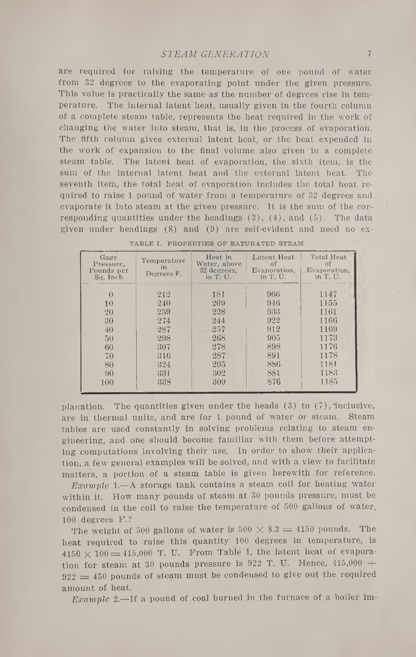
TABLE I. PROPERTIES OF SATURATED STEAM
Gage Pressure,
Pounds per Sq. Inch
Temperature in
Degrees F.
Heat in Water, above
32 degrees, in T. U.
Latent Heat of
Evaporation, in T. U. •
Total Heat of
Evaporation, in T. U.
0 212 181 966 1147 10 240 209 946 1155 20 259 228 933 1161 30 274 244 922 1166 40 287 257 912 1169 50 298 268 905 1173 60 307 278 898 1176 70 316 287 891 1178 80 324 295 886 1181 90 331 302 881 1183
100 338 309 876 1185
planation. The quantities given under the heads (3) to (7), inclusive,
are in thermal units, and are for 1 pound of water or steam. Steam
tables are used constantly in solving problems relating to steam en¬
gineering, and one should become familiar with them before attempt¬
ing computations involving their use. In order to show their applica¬
tion, a few general examples will be solved, and with a view to facilitate
matters, a portion of a steam table is given herewith far reference.
Example 1.—A storage tank contains a steam coil for heating water
within it. How many pounds of steam at 30 pounds pressure, must be
condensed in the coil to raise the temperature of 500 gallons of water,
100 degrees F.? The weight of 500 gallons of water is 500 X 8.3 = 4150 pounds. The
heat required to raise this quantity 100 degrees in temperature, is
4150 X 100 = 415,000 T. U. From Table I, the latent heat of evapora¬
tion for steam at 30 pounds pressure is 922 T. U. Hence, 415,000 -r-
922 — 450 pounds of steam must be condensed to give out the required
amount of heat. Example 2.—If a pound of coal burned in the furnace of a boiler im-
8 No. 67—BOILERS
parts 8000 T. U. to the water, how many pounds will be required to
raise the temperature of 2000 pounds of water from 32 degrees F. and
evaporate it into steam at 80 pounds pressure? How many pounds will
be required to raise the water from a temperature of 50 degrees F. and
evaporate it into steam at 100 pounds pressure? In the first case the total heat of evaporation for steam at 80 pounds
pressure (see Table I) is 1181; hence, 2000 X 1181 = 2,362,000 T. U. are
required. As 1 pound of coal gives 8000 T. U., then, 2,362,000 -r- 8000 =
295 pounds are necessary. In the second case, the temperature of steam at 100 pounds pressure
is 338 degrees F.; therefore, the water must be raised 338 —50 = 288
degrees F. before evaporation begins. This calls for approximately 288
T. U. for each pound of water. The latent heat of evaporation for steam
at 100 pounds pressure is 876 T. U. Hence, 288 -f- 876 = 1164 T. U. must
be given to each pound of water, or a total of 1164 X 2000 = 2,328,000
T. U.; then, 2,328,000 -h 8000 = 291 pounds of coal are required.
Power of Boilers
Boilers are commonly rated in horsepower, although in power work
the evaporation of a certain weight of water under stated conditions is
sometimes called for instead. This, however, is practically the same
thing expressed in a different way. The standard boiler horsepower in
the United States is the capacity to evaporate 30 pounds of water per
hour from a feed-water temperature of 100 degrees F. into dry steam
at 70 pounds gage pressure. This is equivalent, as will be shown later,
to the evaporation of 34.5 pounds of water from a temperature of 212
degrees into steam at atmospheric pressure, which corresponds to 0
pounds gage pressure.
It will be seen by reference to Table I that the total heat of evapora¬
tion varies for different pressures. It is also evident that the heat re¬
quired to furnish a pound of steam will vary with the temperature of
the feed water. This makes it necessary to have some standard when
making a comparison of the capacity and efficiency of different boilers
which are working under different conditions of feed-water temperature
and steam pressure. The standard commonly employed is called the
“equivalent evaporation from and at 212 degrees.” This means, under
any given condition, the equivalent evaporation from a feed-water tem¬
perature of 212 degrees F. into steam at atmospheric pressure.
Example:—A steam boiler is supplied with feed water at a temper¬
ature of 100 degrees F. and carries a pressure of 70 pounds gage. What
is its equivalent evaporation from and at 212 degrees?
The quantity of heat required per pound of steam is found as follows:
Temperature at 70 pounds pressure equals 316 degrees F. Heat re¬
quired to raise the temperature from 100 to 316 degrees is 316 —100 =
216 T. U. Latent heat of evaporation for 70 pounds pressure is 891 T. U.
Therefore, the total heat required per pound of steam is 216 + 891 =
1107 T. U. The heat required to evaporate 1 pound of water from a
temperature of 212 degrees F. into steam at the same temperature (0
STEAM GENERATION 9
gage pressure), is the latent heat of evaporation at this pressure, or
966 T. U. The ratio between 1107 and 966 is 1107 -7- 966 = 1.15’ which
is called the factor of evaporation for 100 degrees feed^water tempera¬
ture and 70 pounds steam pressure. This means that 1.15 times as
much heat is required per pound of steam under the first condition
as under the second, or in other words, the equivalent evaporation from
and at 212 degrees is 30 X 1.15 = 34.5 pounds.
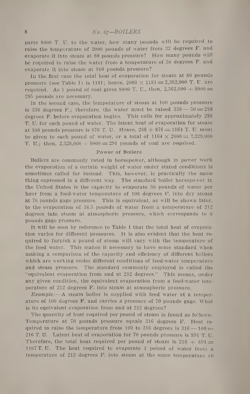
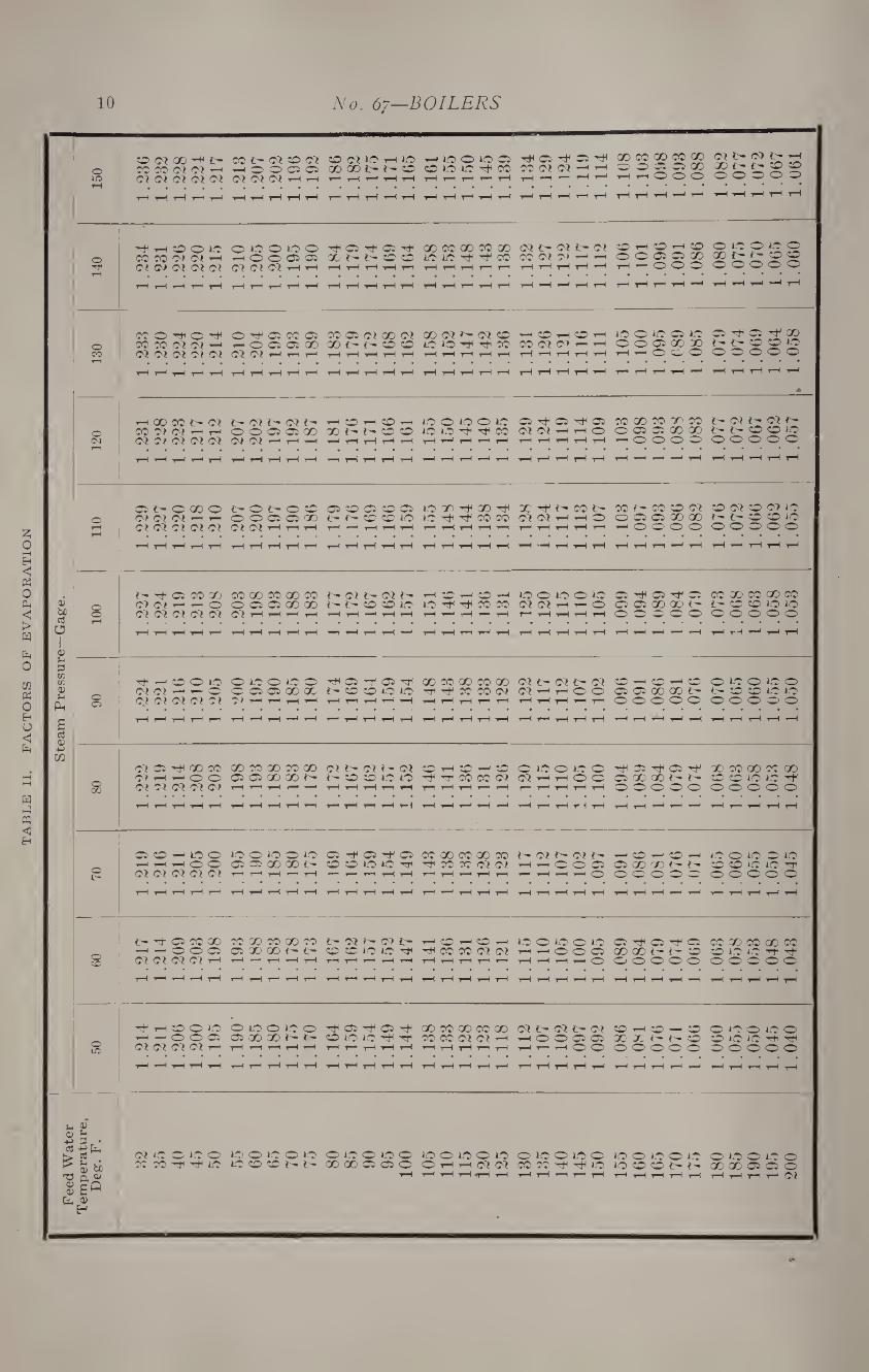
Factors of Evaporation
The factors of evaporation for different combinations of feed-water
temperature and steam pressure have been worked out and put in the
form of a table for convenient use. (See Table II.)
Example 1.—A steam boiler carrying a pressure of 150 pounds per
square inch, and supplied with feed water at a temperature of 60 de¬
grees F., evaporates 300 pounds of water per hour. What is its
equivalent evaporation from and at 212 degrees?
From Table II we find, for the given conditions of temperature and
pressure, that the factor of evaporation is 1.207, which gives 300 X 1.207
= 362 pounds as the equivalent evaporation from and at 212 degrees.
Example 2.—Two boilers of the same commercial rating are operated
under different conditions of temperature and pressure, but are fired
with the same grade of coal. Boiler No. 1 is supplied with feed water
having an average temperature of 50 degrees F., and carries a steam
pressure of 80 pounds per square inch. It evaporates 3000 pounds of
dry steam per hour with a coal consumption of 515 pounds. Boiler
No. 2 is used in connection with a heater and receives its feed water
at a temperature of 200 degrees F. It carries a pressure of 140 pounds
per square inch, and evaporates 3800 pounds of dry steam per hour
with a coal consumption of 575 pounds. Which boiler is the most
efficient—that is, which is evaporating the most dry steam per pound
of coal?
Beginning with boiler No. 1, the first step is to find the evaporation
from and at 212 degrees. The factor of evaporation is found from
Table II to be 1.203, which gives an equivalent total of 3000 X 1.203 =
3609 pounds of steam per hour, or 3609 515 = 7 pounds of steam per
pound of coal. In boiler No. 2 the factor of evaporation is 1.06, and
the equivalent total evaporation 3800 X 1-06 = 4028 pounds of steam
per hour, which gives 4028 -r- 575 = 7 pounds of steam per pound of
coal, the same as in the case of boiler No. 1. Hence, the two boilers
are giving practically the same efficiency, although working under
.different conditions.
Boiler Power for Different Purposes
The boiler power required for different purposes is usually found by
reducing the steam consumption per hour to pounds from and at 212
degrees, and dividing the result by 34.5. In the following are given a
number of methods for determining the weight of steam required for
different purposes.
TA
BL
E
II.
FA
CT
OR
S
OF
EV
AP
OR
AT
ION
10 No. 67—BOILERS L5
0
CD 03 X -H fc-
CC 0? W 01 ^ 03 ®? 03 <0? 03
CO 3- 03 CO 03 H0005 05 03 03 03 t—l t-h
COC3*OHlO GO GO 3- 3- CD T— T-H t-h t-H T-h
t-h *o O *0 05 CO lO lO CO T-H t-H rH t— t-h
OS 35 tJ* CO 03 03 —• rH T-H —1 — t—1 rH
00 CO 00 CO GO 05 O 05 05 GO rH t-h O* O <0
03 3- 03 3- rH
X 3- O CD CD o o o o o
rH rH rH rH tH rH tH rH rH rH t-H rH rH rH rH rH rH rH rH rH rH rH rH rH rH t-H tH rH *-H t-h t-H rH rH rH rH
140
■^hooio CO CO 0'l(MH OJ OJ O? « OI
OlffOiffO rH <0 C* Oi> CQ CQ rH rH
rl* 05 Tt* 05 QOC-C*® ® t-H t-H t-H t-H t-h
GO CO 00 CO 00 io *o ^ ^ co t-h t-h t-h rH t-h
03 3- 03 3- 03 CO 03 O* t-h t-h rH t-H rH t-H rH
O t-h CD t-h CD O O 05 05 00 rH — O O O
0 10 0*00 X 3- 3- CO O o o o o o
rH rH t-H tH rH rH rH rH rH t-H rH rH tH rH rH rH rH rH rH rH rH *-H rH rH t-h rH tH rH t-H rH rH rH ■»—< t-H
130
CO o ^ o tH CO CO 03 03 —i o? o? o? o? o?
O ^ 05 CO 05 rHOOOSOO 03 03 t—i t-h tH
CO 05 C3 00 03 00 ff- 1> ® CO t-h t-H t-H t-H t-H
00 03 3h 03 CO lO 1® r Tt CO t-H t-h tH t-H rH
CD rH CD t-h CO 03 03 -T-H rH
rH t-h rH rH t-H
Iff O *C 05 *o O O 05 GO GO rH rH o O O
05 05 ^ X 3- 3- CD CO 1® O O O O O
rH t-h tH rH rH rH rH rH rH t-h —H rH rH rH rH rH rH rH rH rH rH rH tH t-H rH r^ t-H rH rH «-H rH rH rH ■—H rH
120
t-h 00 CO 3- 03 CO Of «Hri OJ WOJOfO)
i> 03 3^ 03 3- O O 05 05 GO 03 03 T—• T-H T-H
-H CO T-H CD t-H
X 3- 3- CD CO t-h t-h t-h t-h t-h
*0 0*0 0*0 id *® th •'t co T-H t-h t-H t-h t-H
C7 07 rH rH o rH rH rH rH rH
CO 00 CO GO CO O 05 05 00 GO rH O O O O
£- 03 3- 03 3- 3- 3- CO CO 1® o o o o o
t-H rH rH r—< t-H rH rH rH rH rH i rH rH rH rH rH rH rH rH r rH r-1 rH rH rH f-H —4 rH rH rH rH rH tH
110
05 3- O 00 o 03 03 03 i i—i ®? 03 o? o? o?
t-ot-oo O O 05 05 GO 03 03 T-H rH tH
05 CO 05 CO 05 3- 3- co co *® T-h —H t-h t-H t-H
io on h*i oo Tfi io -ct* co co T-H t-H T-h rH T—T
X ^ t"- CO J> 07 07 t-h t-h O r- rH rH rH rH
CO 3- CO CD 03 O CJ5 05 00 00 rH O O O O
CD 03 CD 03 1® 3- 3- CO CO 1® o o o o o
t-H rH t-H t-H t-H rH rH rH rH rH rH rH rH rH rH rH rH rH rH rH t-H rH rH rH rH tH rH rr «—1 rH rH ▼—i rH rH rH
6 bo 03 10
0
^ Q CO GO O C! H ri O o? o? o? o? o?
CO GO CO 00 CO O 05 05 00 00 03 tH h tH tH
3- 03 £~ 03 3* 3- 3- CO CO *® t-H irH —1 t-H t-H
t-h CO T-H CO —H
*0 rt* co CO t-h t-h rH r— rH
10 0*0 0*0 03 03 H t— O t—i rH t—1 t—1 rH
05 05 "Ttf D5 05 05 GO 00 3“ o o o o o
CO X CO X CO 3- CD CD 1® 1® o o o o o
O 1 <v
rH rH t—1 rH r—1 rH rH rH rH rH r-1 rH T—1 T“H —■* rH rH ri rH rH t-H rH rH rH rH H t—H r-H t-H rH rH ■*—1 rH rH
u 3 c/2 C/2 02 U
Ph o a>
Tf-‘®OIO O? 03 — —1 o O? o? 03 o? o?
0 10 0*00 O 05 05 GO 00 03 t—< t— t-h t-h
H# 05 tH 05 Tfl 3- CO co *o *o H t-h ttH t-h ^h
GO CO 'GO CO GO nr1 ^ CO CO 03 rH t-h rH t-h t-h
03 3- 03 3- 03 OJhhOO rH rH rH rH rH
CD -H CD rH CD 05 05 GO GO 3- o o o o o
0*00*00 3- CO CO *® *® o o o o o
s o> +-> m
rH t-H rH rH rH rH rH rH rH rH rH t-H rH rH rH rH rH rH rH t-H rH -rH rH rH t-H i-H rH rH rH rH rH rH rH *—H
o 00
03 05 rH 00 CO O? T—1 T—< O’ O’ O? O? 03 03 O?
GO CO GO CO GO 05 05 X X 3- t-h t-h t-H t—r t—t
03 3- 03 3- 03 3- co co *® *® t-h T-h t-H T—I ^H
CO rH CO —H CO Hfl Tl CO CO 03 r rH rH r— rH
0*00*00 03 rH t-h O O
1—! rH rH rH rH
-rfl 05 05 Tfl 05 GO GO 3 3 o o o o o
X CO X CO X CO CD io io o o o o o
rH rH rH tH t-H rH t-h rH rH rH r-« rH rH rH rH rH rH r—' rH rH t-H rH rH tH rH rH rH —' t-H H r- tH rH rH
o t—
OO^IOO rH rH rH <^>
*0 0*0 0*0 05 05 00 GO 3- t-h t-h t-h t-H
05 rt* 05 05 CO CO *0 *C tt1 — T— T—1 T-H T-h
CO GO CO 00 CO Tt* CO CO C3 03 T-H rH rH t-H rH
3- 03 3- 03 3- T—1 rr O O 05
t-H t-H -^H
—H JO —H CD r H
05 GO *33 0 0 0 0 05
*0 0*0 0*0 CD CD 1® to rr o o o o o
rH rH rH tH t-H rH t-H rH rH rH rH rH rH rH tH t-H rJ rH t-h rH r-l rn rH rH rH rH rH r^ ▼—• ▼—i r— r-J tH rH rH
o ZD
3- 05 co co — O O 05
03 03 03 03 -I-H
CO GO CO GO CO 05 X X 3- 3- rH *— rH rH rH
3— 03 3— 03 3* CO CD lO *® Tji T-H T-H t-H t-H t-H
T—1 CO —H CO rH
H*l CO CO 03 03 rH t-h t-h rH t-h
*0 0*0 0*0 T-H 1—1 o O 05 T-h t-H rH rH 0>
® Tfl 05 ^ 05 00 00 3- 3- CD o o o o o
CO X CO X co CD 1® *® Tf1 Tt* O O O O O
rH rH rH rH rH t-h t-H rH rH t-h rH rH rH rH rH rH rH rH t-H rH rH rH rH rH rH rH rH -^H rH ^H rH rH rH rH rH i
O to
1-1 «o o *® 1—1 — O O 05 03 03 03 03 t-H
0 10 0*00 05 GO GO 3- T-h t-h t-h tH H
Tf* 05 Tfl 05 tJ* CO *0 i® t** Tn T-h t—t t-h tH t—h
00 CO 00 CO GO CO CO 03 03 t-h -T-H rH rH t-h rH
03 3- ®? 3- 03 t-h O O 05 05 rH T— rH O O
CO rH CD —“ CD X' 00 3- 3 CD o o o o o
0*00*00 ■CD *® *® tH rf* o o o o o
rH rH rH rH rH tH tH rH rH rH rH rH rH rH rH rH rH rH rH rH rH rH rH t-H rH t—J rH rH r-H ^ rH H rH rH rH
Feed
Wate
r T
em
pera
ture
, D
eg.
F.
C? ic O iff o CC CO XT T* 1C
1C) O Iff O Iff *o CO CO 3- c-
0*00100 00 00 05 05 O
t-H
*0 0*0 0 10 O t-h t-h 03 03 rH rH rH ^-H rH
0 10 0*00 CO CO Tt* *o rH rH t-h rH rH
*0 0*0 0*0 *0 CD CD 3- 3- rH rH rH rH rH
0*00*00 X X 05 05 o T—1 1—1 T-T T—1 C3
STEAM GENERATION 11
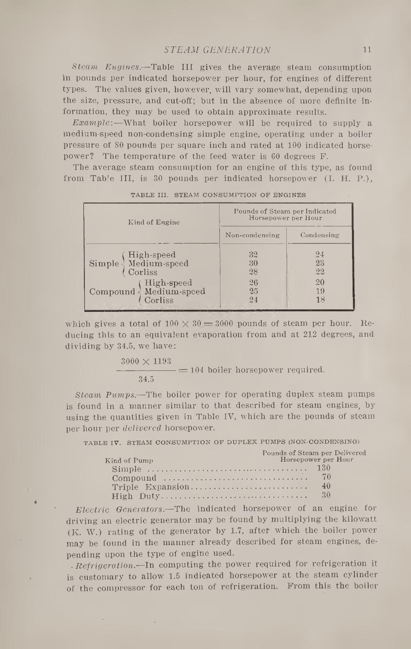
Steam Engines.—Table III gives the average steam consumption
in pounds per indicated horsepower per hour, for engines of different
types. The values given, however, will vary somewhat, depending upon
the size, pressure, and cut-off; but in the absence of more definite in¬
formation, they may be used to obtain approximate results.
Example:—What boiler horsepower will be required to supply a
medium-speed non-condensing simple engine, operating under a boiler
pressure of 80 pounds per square inch and rated at 100 indicated horse¬
power? The temperature of the feed water is 60 degrees F.
The average steam consumption for an engine of this type, as found
from Table III, is 30 pounds per indicated horsepower (I. H. P.),
TABLE III. STEAM CONSUMPTION OP ENGINES
Pounds of Steam per Indicated
Kind of Engine Horsepower per Hour
Non-condensing Condensing
i High-speed Simple ! Medium-speed
32 24 30 23
( Corliss 28 22
L High-speed 26 20 Compound •< Medium-speed 25 19
r Corliss 24 18
which gives a total of 100 X 30 = 3000 pounds of steam per hour. Re¬
ducing this to an equivalent evaporation from and at 212 degrees, and
dividing by 34.5, we have:
3000 X 1193 --=104 boiler horsepower required.
34.5
Steam Pumps.—The boiler power for operating duplex steam pumps
is found in a manner similar to that described for steam engines, by
using the quantities given in Table IV, which are the pounds of steam
per hour per delivered horsepower.
TABLE IV. STEAM CONSUMPTION OF DUPLEX PUMPS (NON-CONDENSING)
Pounds of Steam per Delivered Kind of Pump Horsepower per Hour
Simple . 130 Compound . 70 Triple Expansion. 40 High Duty. 30
Electric Generators.—The indicated horsepower of an engine for
driving an electric generator may be found by multiplying the kilowatt
(K. W.) rating of the generator by 1.7, after which the boiler power
may be found in the manner already described for steam engines, de¬
pending upon the type of engine used. .Refrigeration,—In computing the power required for refrigeration it
is customary to allow 1.5 indicated horsepower at the steam cylinder
of the compressor for each ton of refrigeration. From this the boiler
12 No. 67—BOILERS
power can be determined as already described. In the actual manu¬
facture of ice, twice the power is required as compared with that for
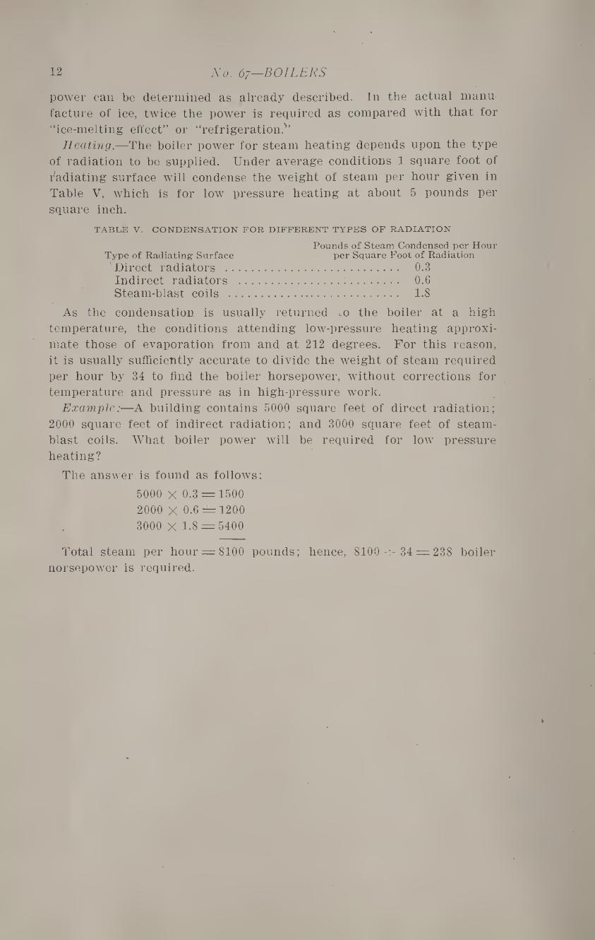
“ice-melting effect” or “refrigeration?’ Heating.—The boiler power for steam heating depends upon the type
of radiation to be supplied. Under average conditions 1 square foot of
radiating surface will condense the weight of steam per hour given in
Table V, which is for low pressure heating at about 5 pounds per
square inch.
TABLE V. CONDENSATION FOR DIFFERENT TYPES OF RADIATION
Pounds of Steam Condensed per Hour Type of Radiating Surface per Square Foot of Radiation
Direct radiators . 0.3 Indirect radiators .:. 0.6 Steam-blast coils . 1.8
As the condensation is usually returned to the boiler at a high
temperature, the conditions attending low-pressure heating approxi¬
mate those of evaporation from and at 212 degrees. For this reason,
it is usually sufficiently accurate to divide the weight of steam required
per hour by 34 to find the boiler horsepower, without corrections for
temperature and pressure as in high-pressure work.
Example:—A building contains 5000 square feet of direct radiation;
2000 square feet of indirect radiation; and 3000 square feet of steam-
blast coils. What boiler power will be required for low pressure
heating?
The answer is found as follows:
5000 X 0.3 = 1500
2000 X 0.6 == 1200
3000 X 1.8 = 5400
Total steam per hour — 8100 pounds; hence, 8100-^ 34 = 238 boiler
norsepower is required.
CHAPTER II
GENERAL PROPORTIONS OF BOILERS
There are certain general proportions which are common to all
boilers, and these will be discussed briefly before taking up the differ¬
ent types in detail. A general description of different types of boilers
will then follow in the next chapter, and subsequently, the design of the
most common form of boiler will be treated.
Heating- Surface
The heating surface of a boiler is commonly defined as that portion
having one side of the plates or tubes exposed to the hot gases and the
other in contact with the water. There is some question as to which side
of the plates should be considered when computing the heating surface,
but it is more common to take the fire surface rather than the water
surface. The capacity of a boiler depends not only upon the amount
of heating surface, but on its arrangement as well. In order to give
the best efficiency, it must be so located as to produce a good distribu¬
tion of the gases and to absorb as much of their heat as possible with¬
out injuring the draft. The best results are secured when the gases
pass over the heating surfaces in such a direction that the hottest gas
will be on the side of the plate opposite the hottest part of the circu¬
lating water. This result is secured in the arrangement shown in
Fig. 2.
In the case of horizontal tubular boilers, of the fire-tube type, it is
customary in calculating the heating surface, to take the sum of one-
half the shell, two-thirds the rear head less the tube area, and the in¬
terior surface of all the tubes. The front head is not counted as heat¬
ing surface, because the gases have become considerably cooled by the
time they reach this point, and also because the direction of flow is
away from the head instead of toward it.
The rating of a boiler is based on the amount of heating surface
which it contains. In the case of horizontal fire-tube boilers of good
design, ic is customary to allow 12 square feet of heating surface per
rated horsepower for power boilers of good size, and about 15 square
feet for heating boilers. The distinction between power and heating
boilers depends simply upon the size of the boiler and the care which
it receives as regards clean heating surfaces and skill in firing. Power
boilers usually receive better care in both these directions, and are
therefore given a somewhat higher rating for a given amount of heat¬
ing surface. Water-tube boilers are rated on a basis of 10 square feet
of heating surface per horsepower, because a large proportion of the
surface is more directly exposed to the fire and hot gases, and also
because the circulation of water is more rapid through the tubes. %
14 No. 67—BOILERS
The weight of coal burned per square foot of grate surface per hour
is called the rate of combustion. This commonly varies from 12 to
18 pounds in the case of power plants operating under natural draft,
running up to 30 pounds or more when forced draft is employed.
With heating boilers, the combustion is somewhat less, it not being
usual to force the boilers so much, except in large plants. Here the
rate drops to 8 or 10 pounds in boilers of medium size, and to 6 or 7
in those of small size, depending upon the care which they receive and
the strength of chimney draft.
The weight of dry steam evaporated per pound of coal is called the
rate of evaporation. This varies with the character of the heating
surface and its relation to the grate area. In power boilers of good
design, the rate of evaporation commonly runs from 9 to 10 pounds,
while in the case of heating boilers, 7 to 8 pounds is more common.
Grate Area
The proper relation between the heating surface and the grate
area depends largely upon the chimney draft, the kind of fuel used,
and also upon the type of boiler and the arrangement of the heating
surface. The grate area in any particular case may be computed by
the following rule, when the probable rates of combustion and evapo¬
ration are known:
Multiply the horsepower of the boiler by 34.5, and divide the result
by the product of the rate of combustion times the rate of evapora¬
tion. The final result will be the required grate area in square feet.
Example 1.—What should be the grate area for a 100 horsepower
boiler in a power plant operating under favorable conditions with
natural draft?
Assuming the rates of combustion and evaporation to be 15 and 10
pounds, respectively, and applying the rule given, we have:
100 X 34.5 -= 23 square feet.
15 X 10
Example 2.— What grate area should be provided for a 40 horse¬
power heating boiler, working under average conditions?
Assuming the rates of combustion and evaporation to be 10 and 8
pounds, respectively, we have:
40 X 34.5 -=17 square feet.
10 X 8
The ratio of the heating surface to the grate area, in the case of
power boilers, is commonly made from 30 to 40 for anthracite, and
from 40 to 50 for bituminous coal. Taking a water-tube boiler rated
on a basis of 10 square feet of heating surface per horsepower, and
assuming a ratio of 40, the grate area is found to be 10 -r- 40 = 0.25
square feet per horsepower. This corresponds very closely to the area
computed by the rule for a rate of combustion of 14 pounds and an
evaporation of 10 pounds. In like manner, a ratio of 50 corresponds
to a combustion of 17 pounds, and an evaporation of 10 pounds.
GENERAL PROPORTIONS 15
Proportions of Steam and Water Space
The steam space must have sufficient volume to act as a storage re¬
servoir so that moisture which may be carried up with the bubbles
of steam may have a chance to fall back. A sufficient volume is also
necessary in order that the intermittent draft of steam made by the
engine will not cause a fluctuation of the steam pressure or water line.
There are various methods of determining the volume of the steam
space. A safe rule in rather common use, is to provide a space equal
to the volume of steam used in 20 seconds. The volume of steam re¬
quired in 20 seconds may be found by the following rule:
Multiply the rated horsepower of the boiler by 34.5, then divide this
product by the product of 180 times the factor of evaporation for the
conditions under which the boiler is to operate. The quotient multi¬
plied by the volume of 1 pound of steam, in cubic feet, at the required
boiler pressure, will give the necessary steam space in cubic feet.
Example:—Find the steam space for an 80 horsepower boiler carry¬
ing 100 pounds pressure per square inch, and having a feed-water tem¬
perature of 50 degrees F.
The necessary data for applying the above rule are as follows:
Horsepower of boiler = 80.
Factor of evaporation for stated conditions = 1.2. Volume of 1 pound of steam at 100 pounds pressure = 3.8 cubic feet.
80 X 34.5 -X 3.8 = 49 cubic feet. 1.2 X 180
A common method employed, in the case of horizontal tubular boil¬
ers, is to carry the water line a distance equal to about 1/3 the diam¬
eter from the top of the shell. This, however, should be checked for
volume and for water surface, the first by the rule just given, and the
second by the method given below: In horizontal tubular boilers the velocity with which the steam
leaves the surface of the water should not exceed about 2.5 feet per
minute. Hence, the volume of steam, in cubic feet, generated per
minute, divided by 2.5, will give the required surface at the water
line. The volume of steam generated per minute may be found by
multiplying the steam space, as computed by the rule previously given,
by 3. Hence in the preceding example, the water surface should be:
49 X 3 •-= 59 square feet.
2.5
An 80 horsepower boiler of usual proportions has a shell 66 inches
in diameter and 16 feet in length. If the water line is carried 1/3 of
the diameter from the top of the shell, it will give a steam space of
approximately 100 cubic feet, and a water surface of 80 square feet,
both of which are well on the side of safety. A boiler should have sufficient water capacity to furnish a reservoir
for supplying suddenly increased demands for steam without diawing
the water line below a safe point or cutting down the pressure.
CHAPTER III
CLASSIFICATION AND TYPES OF BOILERS
Boilers are commonly divided into two classes, externally fired and
internally fired. In the former class the furnace is outside the boiler
(see Figs. 10 and 40), and in the latter, the grate is inside the boiler
proper (see Figs. 4 and 5). These general divisions are subdivided
according to certain details of construction, the most common in sta¬
tionary plants being the fire-tube and water-tube boilers.
Externally fired boilers usually require a brick setting, which is a
matter of considerable expense, but on the other hand, the structure
of the boiler is less complicated, and, hence, less subject to repairs.
The various forms of water-tube boilers in common use are externally
fired. The internally fired boiler is more economical in the use of
fuel, because all heat radiated from the furnace is absorbed by the
water which surrounds it. The expense of a brick setting is also
avoided. Internally fired boilers are more commonly used in marine
and railway practice than in stationary work, although several boilers
of this class are designed especially for power and heating purposes.
Fire-tube Boilers
Boilers of the fire-tube type are so designed that the hot gases pass
through the tubes which are enclosed in a shell and surrounded with
water. The horizontal return tubular boiler is the most common form
of fire-tube boiler, although the vertical form is sometimes used where
floor space is limited. Certain makes of internally fired boilers are
also constructed with fire tubes, as are also the usual types of marine
and locomotive boilers.
The horizontal tubular boiler is extensively used for heating, and to a
considerable extent for power work. Some of the advantages claimed
for this type of boiler are its low first cost, large water capacity, and
its simplicity of construction.
Water-tube Boilers
In the case of water-tube boilers, the construction is the reverse of
the fire-tube boiler, that is, the water is inside the tubes, which are
surrounded by the hot gases. This gives a more rapid circulation to
the water, which increases the efficiency of the heating surface. In
addition to this, the large amount of surface exposed directly to the
fire increases the transmission of heat and prevents overheating. The
draft area, which is sometimes constricted in fire-tube boilers, is al¬
ways ample in this form, which gives a slower movement to the gases
and allows more time for the absorption of their heat by the water.
Other advantages are the rapidity with which steam may be raised,
owing to the water being divided into a large number of small streams
CLASSIFICATION AND TYPES 17
which pass through the hottest part of the fire, and also the safety
due to the same cause, the division of the water into small masses
preventing serious results in case of rupture.
Water-tube boilers represent the latest development in this field,
especially for power work, as fire-tube boilers are seldom used for
pressures as high as 150 pounds per square inch. They are made both
horizontal and vertical in form, the tubes in the former being inclined
upward toward the front in order to assist in the circulation. The
whole arrangement is surrounded with a brick setting, the weight be¬
ing carried by a steel structure built into the brickwork. When prop¬
erly constructed, the different surfaces are easily reached for cleaning,
and being made up of comparatively small parts, are easily transported
and erected. The principal disadvantage is the small amount of
water space, which limits the reserve capacity in case of sudden calls for steam.
Types of Boilers
In the following, brief descriptions will be given of a number of
representative types of both fire-tube and water-tube boilers. There
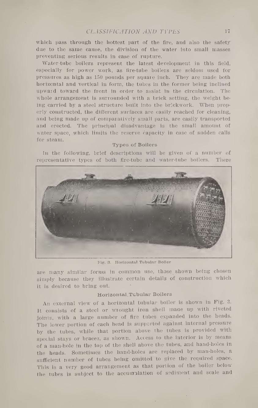
Fig. 3. Horizontal Tubular Boiler
are many similar forms in common use, those shown being chosen
simply because they illustrate certain details of construction which
it is desired to bring out.
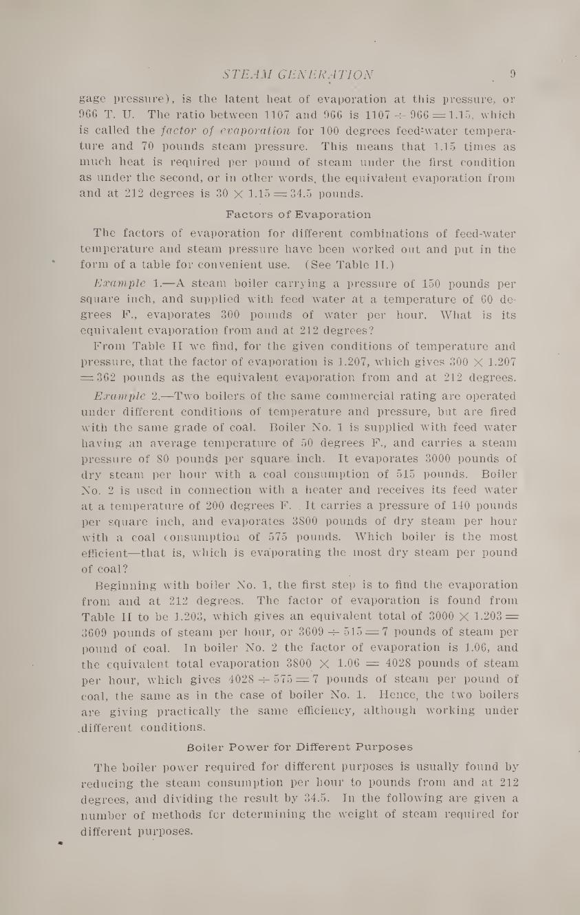
Horizontal.Tubular Boilers
An external view of a horizontal tubular boiler is shown in Fig. 3.
It consists of a steel or wrought iron shell made up with riveted
joints, with a large number of fire tubes expanded into the heads.
The lower portion of each head is supported against internal pressure
by the tubes, while that portion above the tubes is provided with
special stays or braces, as shown. Access to the interior is by means
of a man-hole in the top of the shell above the tubes, and hand-holes in
the heads. Sometimes the hand-holes are replaced by man-holes, a
sufficient number of tubes being omitted to give the required space.
This is a very good arrangement as that portion of the boiler below
the tubes is subject to the accumulation of sediment and scale and
18 No. 67—BOILERS
should be readily accessible for cleaning. When a man-hole is provided
only in the top, it is very difficult, if not impossible, to thoroughly in¬
spect the lower portion of the boiler. The shell is provided with two
nozzles on top, one for the steam connection and one for the safety
valve. The nozzles are shown in the illustration and are usually made
of steel castings or gun metal, although forged steel nozzles are often
employed in the best class of high-pressure work. Heating boilers, and power boilers of small and medium size, are
commonly supported by cast-iron lugs riveted to the shell which rest
on the brickwork of the setting. A better arrangement for high-pres-
Fig. 4. Fitzgibbons Boiler
sure boilers is to suspend them from an overhead construction of steel
girders, thus relieving the brickwork of all load except its own weight.
Fitzgibbons Boiler
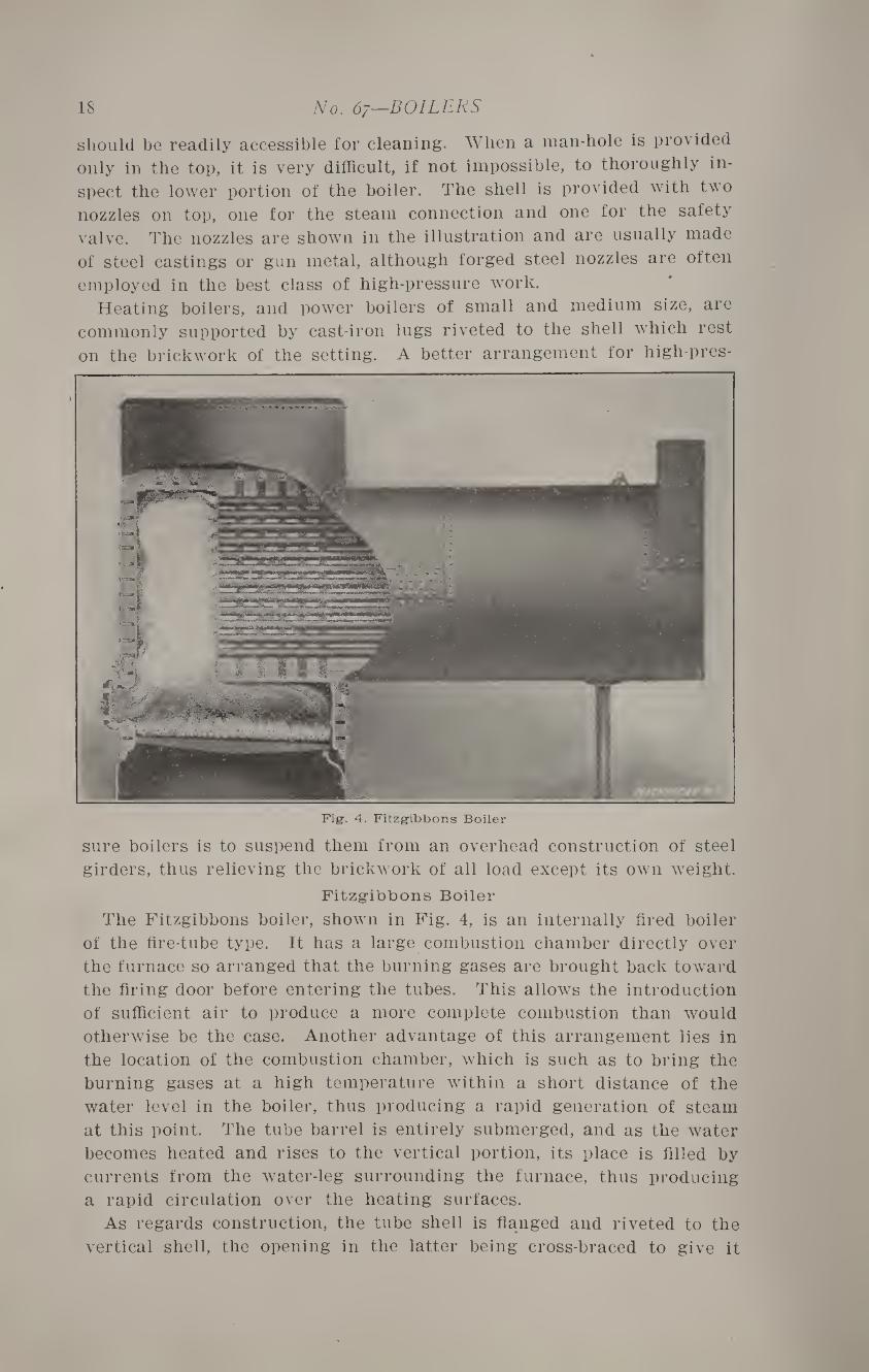
The Fitzgibbons boiler, shown in Fig. 4, is an internally fired boiler
of the fire-tube type. It has a large combustion chamber directly over
the furnace so arranged that the burning gases are brought back toward
the firing door before entering the tubes. This allows the introduction
of sufficient air to produce a more complete combustion than would
otherwise be the case. Another advantage of this arrangement lies in
the location of the combustion chamber, which is such as to bring the
burning gases at a high temperature within a short distance of the
water level in the boiler, thus producing a rapid generation of steam
at this point. The tube barrel is entirely submerged, and as the water
becomes heated and rises to the vertical portion, its place is filled by
currents from the water-leg surrounding the furnace, thus producing
a rapid circulation over the heating surfaces.
As regards construction, the tube shell is flanged and riveted to the
vertical shell, the opening in the latter being cross-braced to give it
CLASSIFICATION AND TYPES 19
the strength of a complete cylinder. In addition to this, the vertical
shell is stayed to the furnace and to the combustion chamber. This
form of boiler requires no brick setting—simply a covering of some good form of plastic or block insulation.
Robb-Mumford Fire-tube Boiler
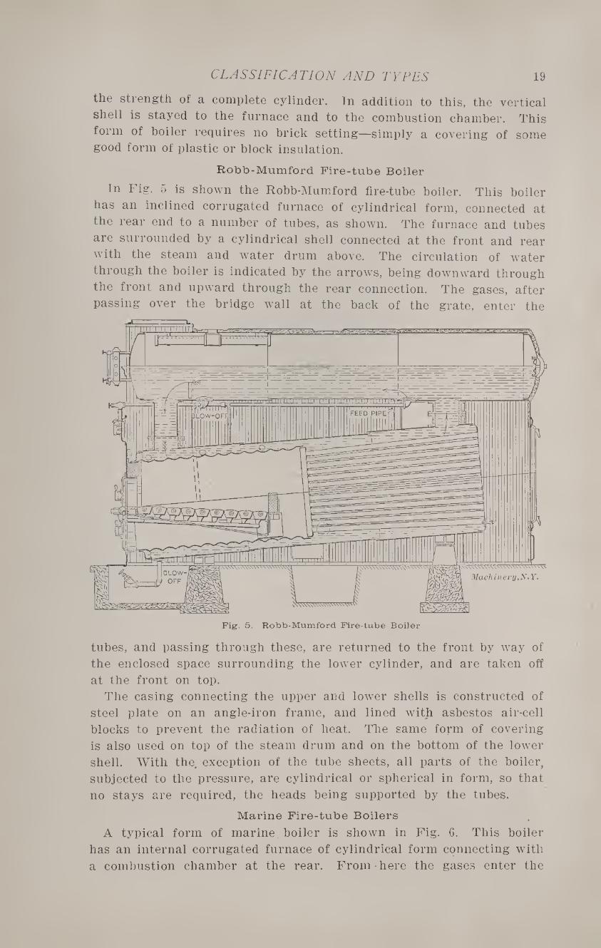
In Fig. 5 is shown the Robb-Mumford fire-tube boiler. This boiler
has an inclined corrugated furnace of cylindrical form, connected at
the rear end to a number of tubes, as shown. The furnace and tubes
are surrounded by a cylindrical shell connected at the front and rear
with the steam and water drum above. The circulation of water
through the boiler is indicated by the arrows, being downward through
the front and upward through the rear connection. The gases, after
passing over the bridge wall at the back of the grate, enter the
tubes, and passing through these, are returned to the front by way of
the enclosed space surrounding the lower cylinder, and are taken off
at the front on top.
The casing connecting the upper and lower shells is constructed of
steel plate on an angle-iron frame, and lined with asbestos air-cell
blocks to prevent the radiation of heat. The same form of covering
is also used on top of the steam drum and on the bottom of the lower
shell. With the exception of the tube sheets, all parts of the boiler,
subjected to the pressure, are cylindrical or spherical in form, so that
no stays are required, the heads being supported by the tubes.
Marine Fire-tube Boilers
A typical form of marine, boiler is shown in Fig. 6. This boiler
has an internal corrugated furnace of cylindrical form connecting with
a combustion chamber at the rear. From-here the gases enter the
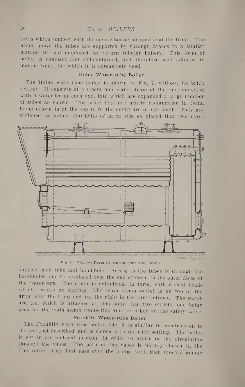
20 No. 67—BOILERS
tubes which connect with the smoke bonnet or uptake at the front. The
heads above the tubes are supported by through braces in a similar
manner to that employed for return tubular boilers; This form of
boiler is compact and self-contained, and therefore well adapted to
marine work, for which it is extensively used.
Heine Water-tube Boiler
The Heine water-tube boiler is shown in Fig. 7, without its brick
setting. It consists of a steam and water drum at the top connected
with a water-leg at each end, into which are expanded a large number
of tubes as shown. The water-legs are nearly rectangular in form,
being drawn in at the top to fit the curvature of the shell. They are
stiffened by hollow stay-bolts of large size so placed that two stays
support each tube and hand-hole. Access to the tubes is through the
hand-holes, one being placed over the end ot each, in the outer faces of
the water-legs. The drum is cylindrical in form, with dished heads
which require no staying. The main steam outlet is on top of the
drum near the front end (at the right in the illustration). The stand¬
ard tee, which is attached at this point, has two outlets, one being
used for the main steam connection and the other for the safety valve.
Franklin Water-tube Boiler
The F ranklin water-tube boiler, Fig. 8, is similar in construction to
the one just described, and is shown with its brick setting. The boiler
is set in an inclined position in order to assist in the circulation
thi ough the tubes. The path of the gases is plainly shown in the
illustration; they first pass over the bridge wall, then upward among

CLASSIFICATION AND TYPES 21
the tubes, and forward to an opening at the front, and then backward
again under the main drum to the smoke uptake at the rear. Two
deflecting walls of tile laid on the tubes serve to make the gases take
Fig. 7. Heine Water-tube Boiler
this course, this causing a large proportion of their heat to be ab¬
sorbed by the water within the boiler.
The steam outlet is at the front of the main drum on top, and dry
steam is insured by the use of a dry pipe and deflecting plate directly
Fig. 8. Franklin Water-tube Boiler
below it which prevents spray from being carried over with the steam,
even when the boiler is being forced. The water column connection
is made with the front of the main drum, and a mud drum of thin
22 No. 6y—BOILERS
steel occupies the position shown partly by dotted lines. The feed
water is discharged into this, where it is heated and deposits its im¬
purities, which may be blown off from time to time through a pipe at
the rear, as may be required.
Keeler Water-tube Boiler
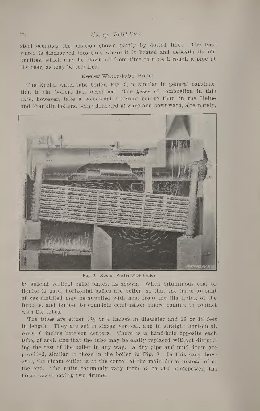
The Keeler water-tube boiler, Fig. 9, is similar in general construc¬
tion to the boilers just described. The gases of combustion in this
case, however, take a somewhat different course than in the Heine
and Franklin boilers, being deflected upward and downward, alternately,
Fig. 9. Keeler Water-tube Boiler
by special vertical baffle plates, as shown. When bituminous coal or
lignite is used, horizontal baffles are better, so that the large amount
of gas distilled may be supplied with heat from the tile lining of the
furnace, and ignited to complete combustion before coming in contact
with the tubes.
The tubes are either 3y2 or 4 inches in diameter and 16 or 18 feet
in length. They are set in zigzag vertical, and in straight horizontal,
rows, 6 inches between centers. There is a hand-hole opposite each
tube, of such size that the tube may be easily replaced without disturb¬
ing the rest of the boiler in any way. A dry pipe and mud drum are
provided, similar to those in the boiler in Fig. 8. In this case, how¬
ever, the steam outlet is at the center of the main drum instead of at
the end. The units commonly vary from 75 to 300 horsepower, the
larger sizes having two drums.
CLASSIFICATION AND TYPES
Babcock and Wilcox Water-tube Boiler
23
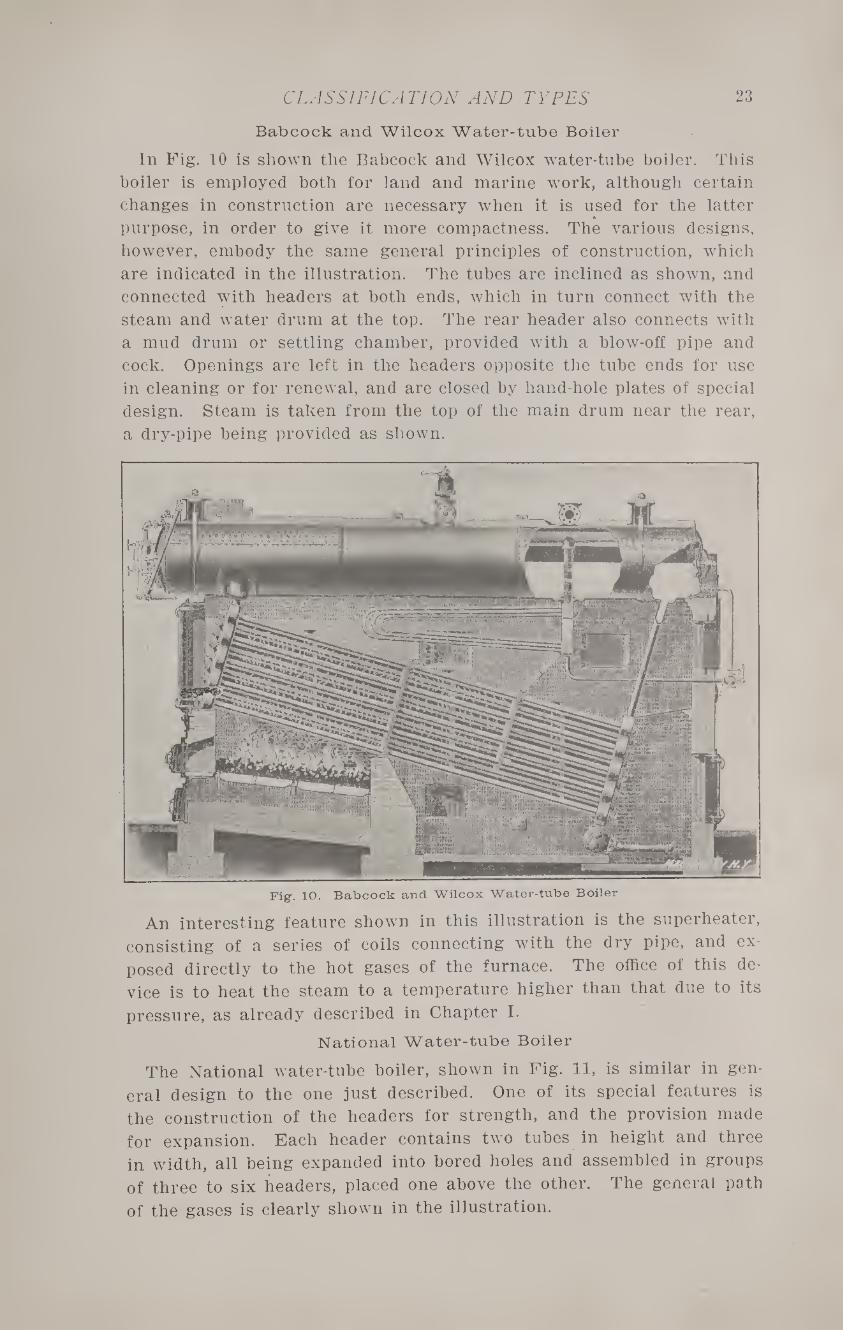
In Fig. 10 is shown the Babcock and Wilcox water-tube boiler. This
boiler is employed both for land and marine work, although certain
changes in construction are necessary when it is used for the latter
purpose, in order to give it more compactness. The various designs,
however, embody the same general principles of construction, which
are indicated in the illustration. The tubes are inclined as shown, and
connected with headers at both ends, which in turn connect with the
steam and water drum at the top. The rear header also connects with
a mud drum or settling chamber, provided with a blow-off pipe and
cock. Openings are left in the headers opposite the tube ends for use
in cleaning or for renewal, and are closed by hand-hole plates of special
design. Steam is taken from the top of the main drum near the rear,
a dry-pipe being provided as shown.
Fig. 10. Babcock and Wilcox Water-tube Boiler
An interesting feature shown in this illustration is the superheater,
consisting of a series of coils connecting with the dry pipe, and ex¬
posed directly to the hot gases of the furnace. The office of this de¬
vice is to heat the steam to a temperature higher than that due to its
pressure, as already described in Chapter I.
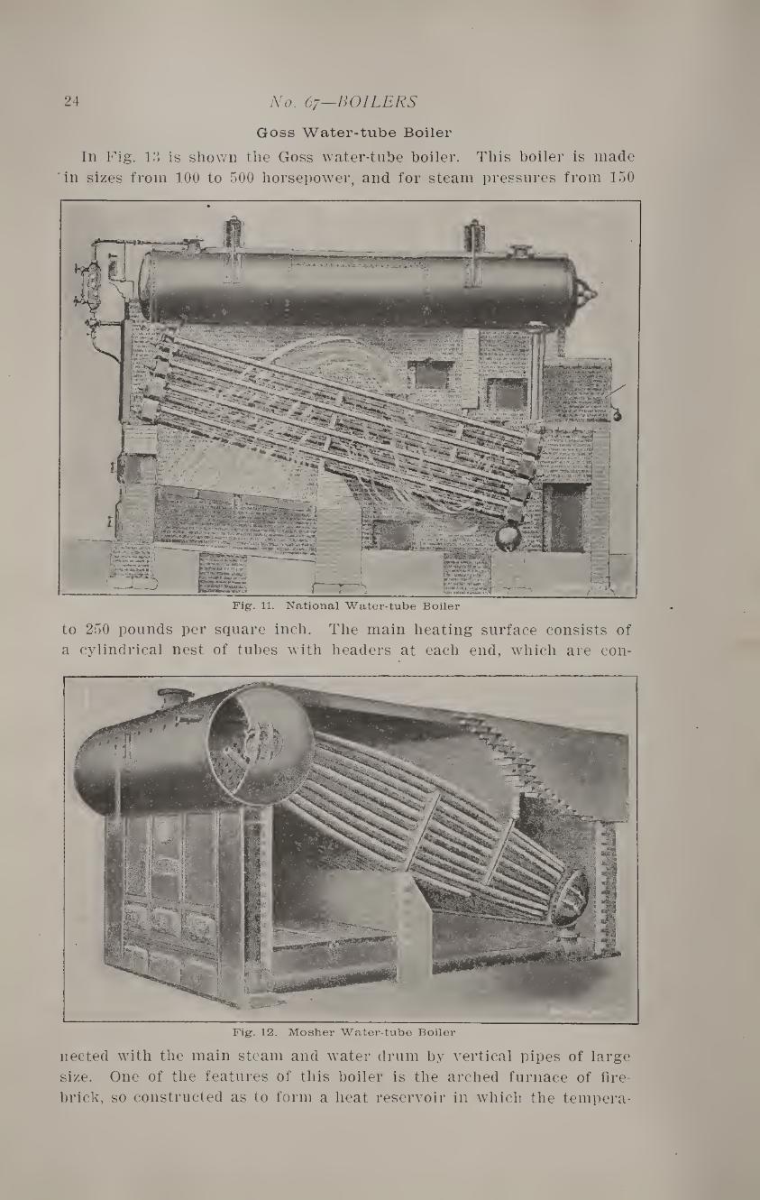
National Water-tube Boiler
The National water-tube boiler, shown in Fig. 11, is similar in gen¬
eral design to the one just described. One of its special features is
the construction of the headers for strength, and the provision made
for expansion. Each header contains two tubes in height and three
in width, all being expanded into bored holes and assembled in groups
of three to six headers, placed one above the other. The general path
of the gases is clearly shown in the illustration.
24 No. 67—BOILERS
Goss Water-tube Boiler
In Fig. 13 is shov/n the Goss water-tube boiler. This boiler is made
'in sizes from 100 to 500 horsepower, and for steam pressures from 150
Pig. 11. National Water-tube Boiler
to 250 pounds per square inch. The main heating surface consists of
a cylindrical nest of tubes with headers at each end, which are con-
Fig. 12. Mosher Water-tube Boiler
nected with the main steam and water drum by vertical pipes of large
size. One of the features of this boiler is the arched furnace of fire¬
brick, so constructed as to form a heat reservoir in which the tempera-
25 CLASSIFICATION AND TYPES
ture can be maintained at a point where the gases from the volatile
matter will be ignited after thoroughly mixing with the inflowing air.
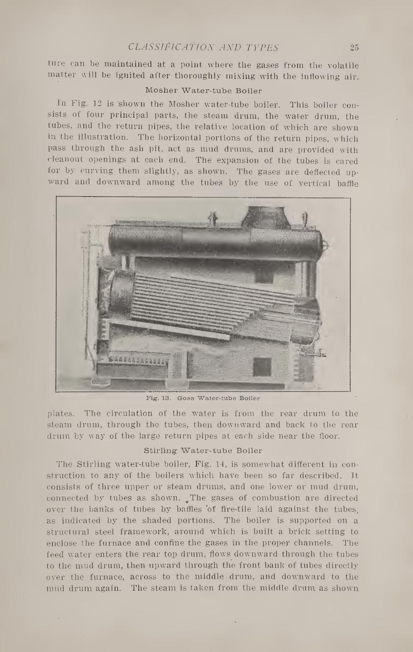
Mosher Water-tube Boiler
In Fig. 12 is shown the Mosher water-tube boiler. This boiler con¬
sists of four principal parts, the steam drum, the water drum, the
tubes, and the return pipes, the relative location of which are shown
in the illustration. The horizontal portions of the return pipes, which
pass through the ash pit, act as mud drums, and are provided with
cleanout openings at each end. The expansion of the tubes is cared
for by curving them slightly, as shown. The gases are deflected up¬
ward and downward among the tubes by the use of vertical baffle
Fig. 13. Goss Water-tube Boiler
plates. The circulation of the water is from the rear drum to the
steam drum, through the tubes, then downward and back to the rear
drum by way of the large return pipes at each side near the floor.
Stirling1 Water-tube Boiler
The Stirling water-tube boiler, Fig. 14, is somewhat different in con¬
struction to any of the boilers which have been so far described. It
consists of three upper or steam drums, and one lower or mud drum,
connected by tubes as shown. #The gases of combustion are directed
over the banks of tubes by baffles of fire-tile laid against the tubes,
as indicated by the shaded portions. The boiler is supported on a
structural steel framework, around which is built a brick setting to
enclose the furnace and confine the gases in the proper channels. The
feed water enters the rear top drum, flows downward through the tubes
to the mud drum, then upward through the front bank of tubes directly
over the furnace, across to the middle drum, and downward to the
mud drum again. The steam is taken from the middle drum as shown
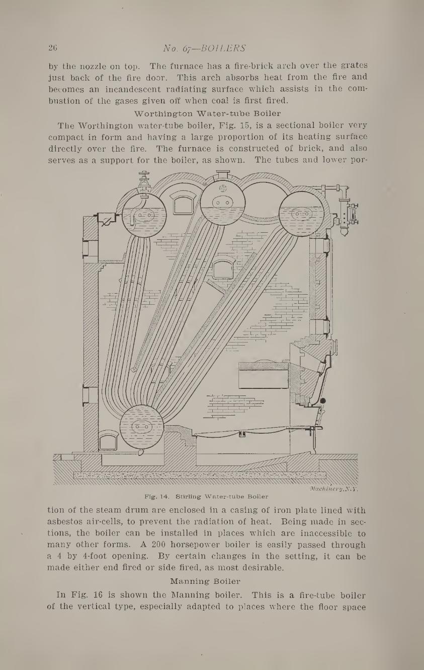
26 No. 67—BOILERS
by the nozzle on top. The furnace has a fire-brick arch over the grates
just back of the fire door. This arch absorbs heat from the fire and
becomes an incandescent radiating surface which assists in the com¬
bustion of the gases given off when coal is first fired.
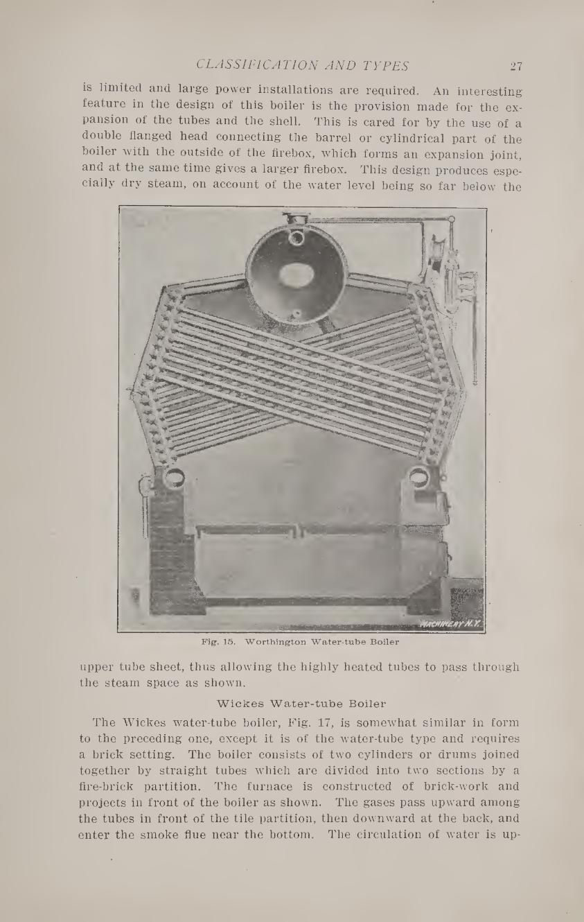
Worthington Water-tube Boiler
The Worthington water-tube boiler, Fig. 15, is a sectional boiler very
compact in form and having a large proportion of its heating surface
directly over the fire. The furnace is constructed of brick, and also
serves as a support for the boiler, as shown. The tubes and lower por¬
tion of the steam drum are enclosed in a casing of iron plate lined with
asbestos air-cells, to prevent the radiation of heat. Being made in sec¬
tions, the boiler can be installed in places which are inaccessible to
many other forms. A 200 horsepower boiler is easily passed through
a 4 by 4-foot opening. By certain changes in the setting, it can be
made either end fired or side fired, as most desirable.
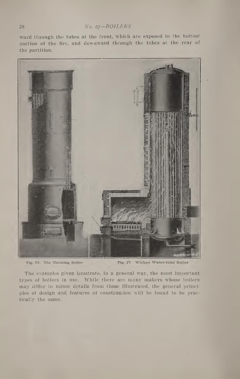
Manning Boiler
In Fig. 16 is shown the Manning boiler. This is a fire-tube boiler
of the vertical type, especially adapted to places where the floor space
27 CLASSIFICATION AND TYPES
is limited and large power installations are required. An interesting-
feature in the design of this boiler is the provision made for the ex¬
pansion of the tubes and the shell. This is cared for by the use of a
double flanged head connecting the barrel or cylindrical part of the
boiler with the outside of the firebox, which forms an expansion joint,
and at the same time gives a larger firebox. This design produces espe¬
cially dry steam, on account of the water level being so far below the
Fig. 15. Worthington Water-tube Boiler
upper tube sheet, thus allowing the highly heated tubes to pass through
the steam space as shown.
Wickes Water-tube Boiler
The Wickes water-tube boiler, Fig. 17, is somewhat similar in form
to the preceding one, except it is of the water-tube type and requires
a brick setting. The boiler consists of two cylinders or drums joined
together by straight tubes which are divided into two sections by a
fire-brick partition. The furnace is constructed of brick-work and
projects in front of the boiler as shown. The gases pass upward among
the tubes in front of the tile partition, then downward at the back, and
enter the smoke flue near the bottom. The circulation of water is up-
28 No. 67—BOILERS
ward through the tubes at the front, which are exposed to the hottest
portion of the fire, and downward through the tubes at the rear of
the partition.
Fig. 16. The Manning Boiler Fig. 17. Wickes Water-tube Boiler
The examples given illustrate, in a general way, the most important
types of boilers in use. While there are many makers whose boilers
may differ in minor details from those illustrated, the general princi¬
ples of design and features of construction will be found to be prac¬
tically the same.
CHAPTER IV
DESIGN OF HORIZONTAL TUBULAR BOILERS
There are so many forms of water-tube boilers in use that no attempt
will be made to consider their design in detail. The case of the hori¬
zontal fire-tube boiler is different, and the engineer should be able to
decide upon the general proportions to be employed, rather than leave
it to the manufacturers. Although the rating is based on the amount
of heating surface, the efficiency will depend to a considerable extent
upon its form and general arrangement. The type of riveted joints and
the method of bracing are important details, which should be under the general direction of the engineer.
Materials
Both wrought-iron and mild steel are used in the construction of
boilers, for the shell, tubes, rivets and stays. Cast-iron is only used for
man-hole frames and covers, hand-holes, nozzles, and brackets.
Wrought-iron and steel are often used for these also, in the best class
of work for high pressure boilers.
When wrought-iron plate is used for boiler construction, it should
have an ultimate tensile strength varying from 50,000 to 60,000 pounds
per square inch; an elongation of 10 to 15 per cent in a test piece 8
inches long; and a contraction of 40 per cent at fracture.
A large proportion of boilers at the present time aie made of open-
hearth steel. So-called flange steel is generally used for the heads,
this being an especially tough and ductile quality of open-hearth steel.
The only advantage in the use of wrought-iron plates is their greater
ductility, which requires less care in working. The steel used for
shells should have a tensile strength varying from 60,000 to 75,000
pounds per square inch, with an elongation of 20 per cent, and a con¬
traction of 50 per cent at fracture. Flange steel for the heads should
have a tensile strength of 52,000 to 60,000 pounds per square inch; an
elongation of 25 per cent; and a contraction of 45 per cent for plates
y2 inch in thickness, and 40 per cent for %-inch plates.
The braces, if made without welds, are commonly of steel similar to
that used for the heads. The rivets are commonly forged from
wrought-iron, having a tensile strength of 50,000 pounds, and a shear¬
ing strength of 40,000 pounds per square inch of section. They should
have an elongation of 18 per cent, and a contraction in area of 40
per cent at fracture. They should stand bending aouble without frac¬
ture when cold, and be capable of being hammered cold to %-inch in
thickness without fraying at the edges.
Testing1 the Materials
The meaning of the various terms, relating to strength, used aoove,
are best explained by a brief description of the tests employed for as-
30 No. 67—BOILERS
certaining the strength of the materials. Pieces for testing are cut
from the side of the plate, of such width that the sectional area shall
be approximately 0.4 of a square inch.
The tensile strength is found by pulling the piece apart in a testing
machine, and dividing the total force necessary, in pounds, by the sec¬
tional area of the test piece. This gives the ultimate or breaking
strength in pounds per square inch. To test the elongation, the test
piece is placed in the jaws of the machine, and a length of 8 inches
marked upon it. It is then pulled apart, and the final length of the
marked piece measured. The difference between the original and final
lengths, divided by 8, gives the elongation in one inch, from which the
percentage of elongation is readily determined. The contraction is
found by subtracting the area at the point of fracture from the area
before the test was made, and dividing this difference by the original
area of the test piece. This quotient multiplied by 100 gives the per¬
centage of contraction and indicates the ductility.
Punching- and Drilling Plates
When the rivet holes are punched, the metal between the holes is
weakened, hence in the best class of work the holes are drilled with the
plates in position. In some cases practically the same results are ob¬
tained by punching the holes somewhat smaller than required and
drilling or reaming them to size afterward.
Thickness of Plates
The bursting pressure of a cylindrical shell is found by the follow¬ ing equation
2 t S P —--
cl
in which p = pounds pressure per square inch,
t = thickness of shell plate, in inches,
S = ultimate tensile strength, in pounds per square inch,
d = diameter of shell, in inches.
This formula is for a solid shell without joists; hence, in case of a
boiler, the result must be multiplied by the efficiency of the riveted
joint used. In practice, the strength of a boiler is also made from five
to six times greater than is required for the working pressure, that is,
the pressure ordinarily carried is only about one-sixth of the bursting
pressure. The margin of strength is called the factor of safety. The
following table gives the safe working pressures for boilers of different
size and thickness of plate, made up with solid plates. To find the
safe working pressure in any particular case, multiply the pressure in
the table by the efficiency of the joint used.
Example 1:—What is the safe working pressure for a 54-inch boiler
with %-inch plates, made up with riveted joints having an efficiency of 80 per cent?
The safe pressure from Table VI for solid plates is 130, and for the
type of joint used, it is 130 X 0.80 = 104 pounds per square inch.
DESIGN 31
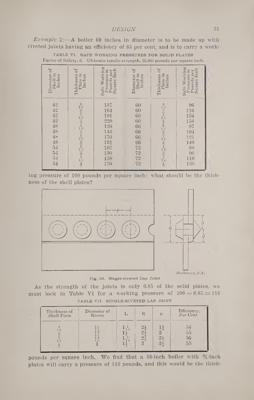
Example 2:—A boiler 60 inches in diameter is to be made up with
riveted joints having an efficiency of 85 per cent, and is to carry a work-
TABLE VI. SAFE WORKING PRESSURES FOR SOLID PLATES
Factor of Safety, 6. Ultimate tensile strength, 55,000 pounds per square inch.
ing pressure of 100 pounds per square inch; what should be the thick¬
ness of the shell plates?
As the strength of the joints is only 0.85 of the solid plates, we
must look in Table VI for a working pressure of 100 -r- 0.85 = 118
TABLE VII. SINGLE-RIVETED LAP JOINT
Thickness of Diameter of R
Efficiency, Shell Plate Rivets L p Per Cent
5 1 6
11 T6 ItV 1! 54
t 1 « 1 6 n 2* 2 55
7 1 6
1 5 1 6 ir7. • n 56
i 1 H 3 2i 55
pounds per square inch. We find that a 60-inch boiler with %-inch
plates will carry a pressure of 116 pounds, and this would be the thick-
32 No. 67—BOILERS
ness to be used. In practice, an additional 1/16 inch is usually al¬
lowed to offset the effects of corrosion and add to the life of the boiler.
Boiler heads are commonly made Vs inch thicker than the shell.
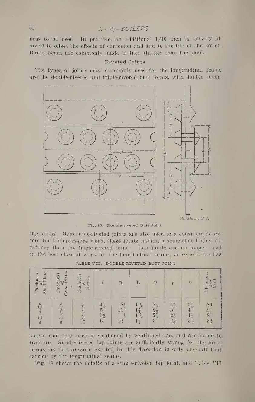
Riveted Joints
The types of joints most commonly used for the longitudinal seams
are the double-riveted and triple-riveted butt joints, with double cover-
Mach inery,y, y,
Fig. 19. Double-riveted Butt Joint
ing strips. Quadruple-riveted joints are also used to a considerable ex¬
tent for high-pressure work, these joints having a somewhat higher ef¬
ficiency than the triple-riveted joint. Lap joints are no longer used
in the best class of work for the longitudinal seams, as experience has
TABLE VIII. DOUBLE-RIVETED BUTT JOINT
CO 3 CO M 5 «H Pi ^ 0- 1c £
CO CO $ ta
M'S* .2 fc ■ J3 > >
iam
ete
r of
Riv
ets
A B L R p P
ffic
ien
cy
, P
er
Cent
H a l—l W
5 1 6
5 1 6 ft 8* n If 8ft 80
1 1 i 5 10 n 2 4 81 7
T<5 7
TS l 5| lift 1* 2ft 4| 81 i i 15
T6 6 12 ift 8 2f 82
shown that they become weakened by continued use, and are liable to
fracture. Single-riveted lap joints are sufficiently strong for the girth
seams, as the pressure exerted in this direction is only one-half that
carried by the longitudinal seams.
Fig. 18 shows the details of a single-riveted lap joint, and Table VII
DESIGN 33
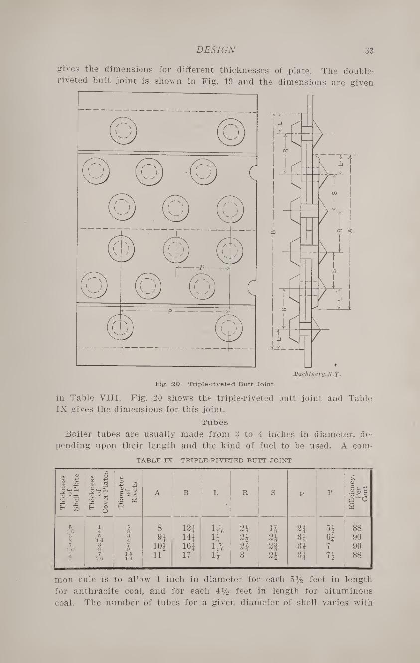
gives the dimensions for different thicknesses of plate. The double-
riveted butt joint is shown in Fig. 19 and the dimensions are given
in Table VIII. Fig. 20 shows the triple-riveted butt joint and Table
IX gives the dimensions for this joint.
Tubes
Boiler tubes are usually made from 3 to 4 inches in diameter, de¬
pending upon their length and the kind of fuel to be used. A com-
TABLE IX. TRIPLE-RIVETED BUTT JOINT
Th
ick
ness
of
Shell P
late
Th
ick
ness
of
Co
ver
Pla
tes
Dia
mete
r of
Riv
ets
A B L •
R s p p
Eff
icie
ncy
, P
er
Cent
5 i 1 8 12£ lys 24 H 2| 54 88 1 tV 1 H 14* H 24 24 34 64 90
T76
4 t 10} m 1* 24 2* 34 7 90
T76 1 5 1 6 li 17 H 3 24 3| ?4 88
mon rule is to aPow 1 inch in diameter for each 5y2 feet in length
for anthracite coal, and for each 4y2 feet in length for bituminous
coal. The number of tubes for a given diameter of shell varies with
34 No. 67—BOILERS
different manufacturers. In general, there should be a clear space of
1 inch between the tubes in both directions, and at least 3 inches be¬
tween the outer tubes and the shell. The circulation will also be some¬
what improved if the central vertical space is increased to two inches.
The number of 3-inch tubes recommended for boilers of different diam¬
eters is given in Table X. In addition, this table gives the rated horse-
TABLE X. NUMBER OF TUBES AND HORSEPOWER OF BOILERS
Diameter of Shell, Inches
Number of 3-inch Tubes
Horsepower per Foot in Length of Tubes and
Shell
Diameter of Shell, Inches
Number of 3-inch Tubes
Horsepower per Foot in Length of Tubes and
Shell
42 34 2.5 60 72 5.0 48 44 3.2 66 90 6.2 54 54 3.9 72 114 7.7
power for each foot in length of tubes and shell, based on 12 square
feet of heating surface per horsepower.
Custom has established a certain relation between the diameter and
length of shell. This relation under ordinary conditions may be taken
as follows: Diameter, 42 inches, length, 10 to 13 feet; diameter, 48
inches, length, 11 to 14 feet; diameter, 54 inches, length, 12 to 15 feet;
diameter, 60 inches, length, 13 to 16 feet; diameter, 66 inches, length,
14 to 17 feet; diameter, 72 inches, length, 15 to 18 feet.
Example 1:—What is-the rated horsepower of a 66-inch boiler with
90 3-inch tubes, 16 feet long? From Table X we find that the horse¬
power per foot is 6.2; hence 6.2 x 16 = 99.2 horsepower.
Example 2:—What should be the dimensions of a 70 horsepower
DESIGN 35
boiler, using 3-inch tubes? From Table X we find that a section of
a 60-inch boiler 1 foot in length is rated at 5 horsepower. Then 70
~ ^ feet, is the required length to give the required horsepower.
The proportions are often varied somewhat according to the available
space in the boiler room, but should be kept within certain limits to
get the best results. The diagrams of tube sheets, of different diam¬
eters, in Figs. 26 to 33, inclusive, show the arrangement for 3-inch
tubes. If it is desired to use tubes of another size, they can be ar¬
ranged to co\ei about the same area, with the same spaces between
them as for 3-inch tubes. In computing the heating surface, it will
be sufficiently accurate to allow 0.8, 0.9, and 1.0 square foot of heating
surface for 1 linear foot of 3-inch, S^-inch, and 4-inch boiler tubes, respectively.
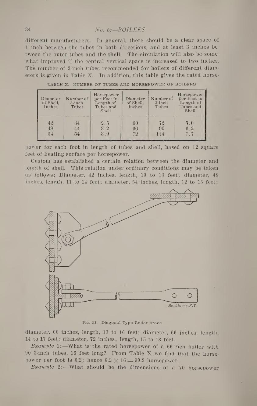
Bracing-
The bracing or staying of the portion of the heads above the tubes
is an important detail in the design and construction of tubular boilers.
There are twTo general methods of doing this, known as “crow-foot” or
diagonal bracing and “through” bracing.
The brace shown in Fig. 21 is of the diagonal type. It is provided
with a forked head at one end, which is attached to a piece of tee-iron
riveted to the boiler head. The other end is riveted directly to the
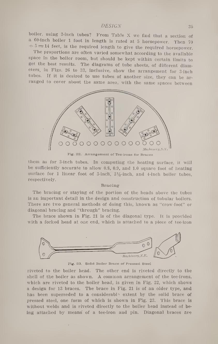
shell of the boiler as shown. A common arrangement of the tee-irons,
which are riveted to the boiler head, is given in Fig. 22, which shows
a design for 13 braces. The brace in Fig. 21 is of an older type, and
has been superseded to a considerable extent by the solid brace of
pressed steel, one form of which is shown in Fig. 23. This brace is
without welds and is riveted directly to the boiler head instead of be¬
ing attached by means of a tee-iron and pin. Diagonal braces are
36
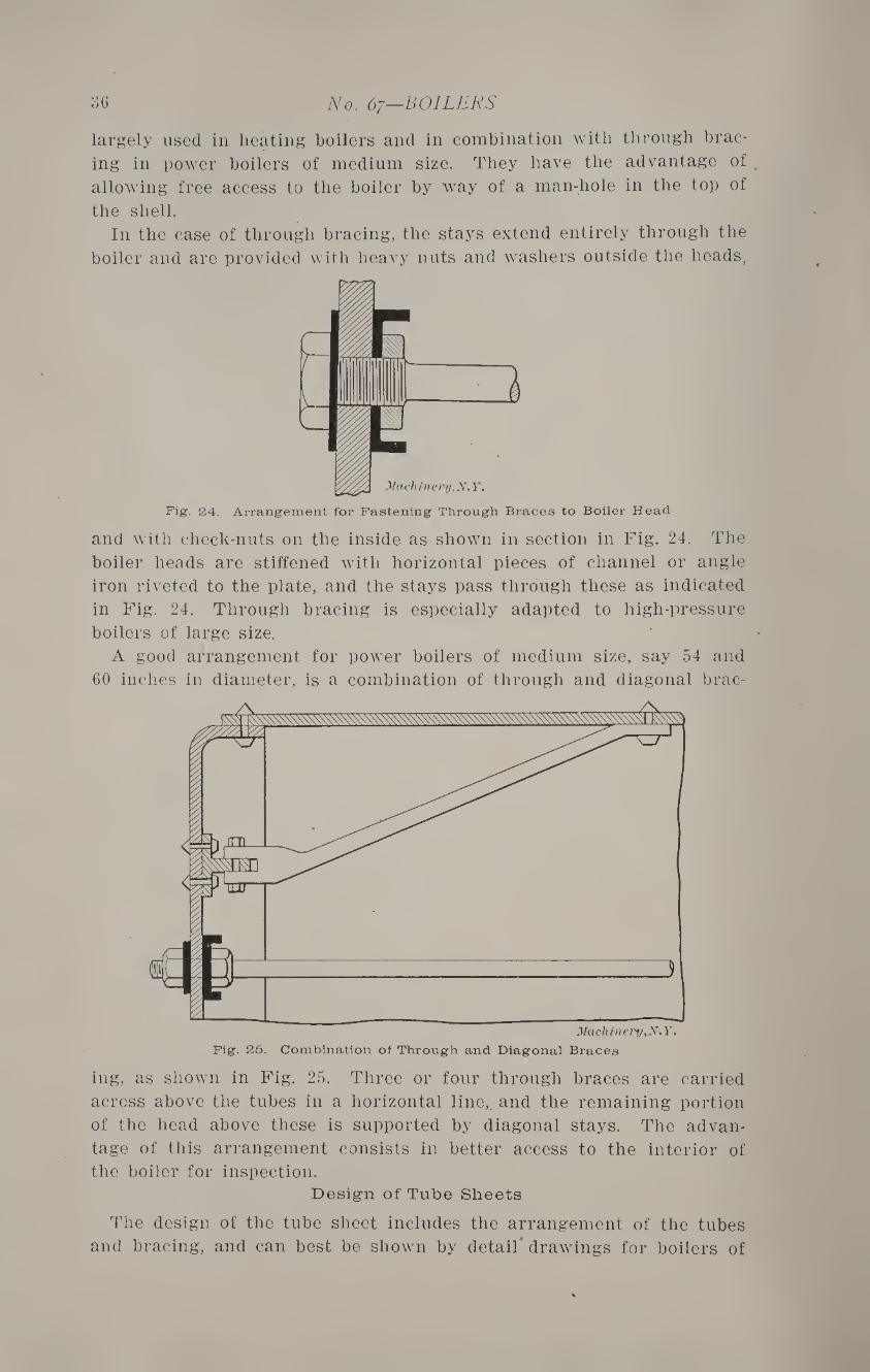
Fig. 25. Combination of Through and Diagonal Braces
ing, as shown in Fig. 25. Three or four through braces are carried
across above the tubes in a horizontal line,, and the remaining portion
of the head above these is supported by diagonal stays. The advan¬
tage of this arrangement consists in better access to the interior of the boiler for inspection.
Design of Tube Sheets
The design of the tube sheet includes the arrangement of the tubes
and bracing, and can best be shown by detail drawings for boilers of
No. 67—BOILERS
largely used in heating boilers and in combination with through brac¬
ing in power boilers of medium size. They have the advantage of
allowing free access to the boiler by wray of a man-hole in the top of
the shell. In the case of through bracing, the stays extend entirely through the
boiler and are provided with heavy nuts and washers outside the heads,
Machinery, N. Y.
Fig. 24. Arrangement for Fastening Through Braces to Boiler Head
and with check-nuts on the inside as shown in section in Fig. 24. The
boiler heads are stiffened with horizontal pieces of channel or angle
iron riveted to the plate, and the stays pass through these as indicated
in Fig. 24. Through bracing is especially adapted to high-pressure
boilers of large size.
A good arrangement for power boilers of medium size, say 54 and
60 inches in diameter, is a combination of through and diagonal brae-
DESIGN 37
standard sizes. The computations for this part of the work are some¬
what complicated, especially for through bracing, and can hardly be
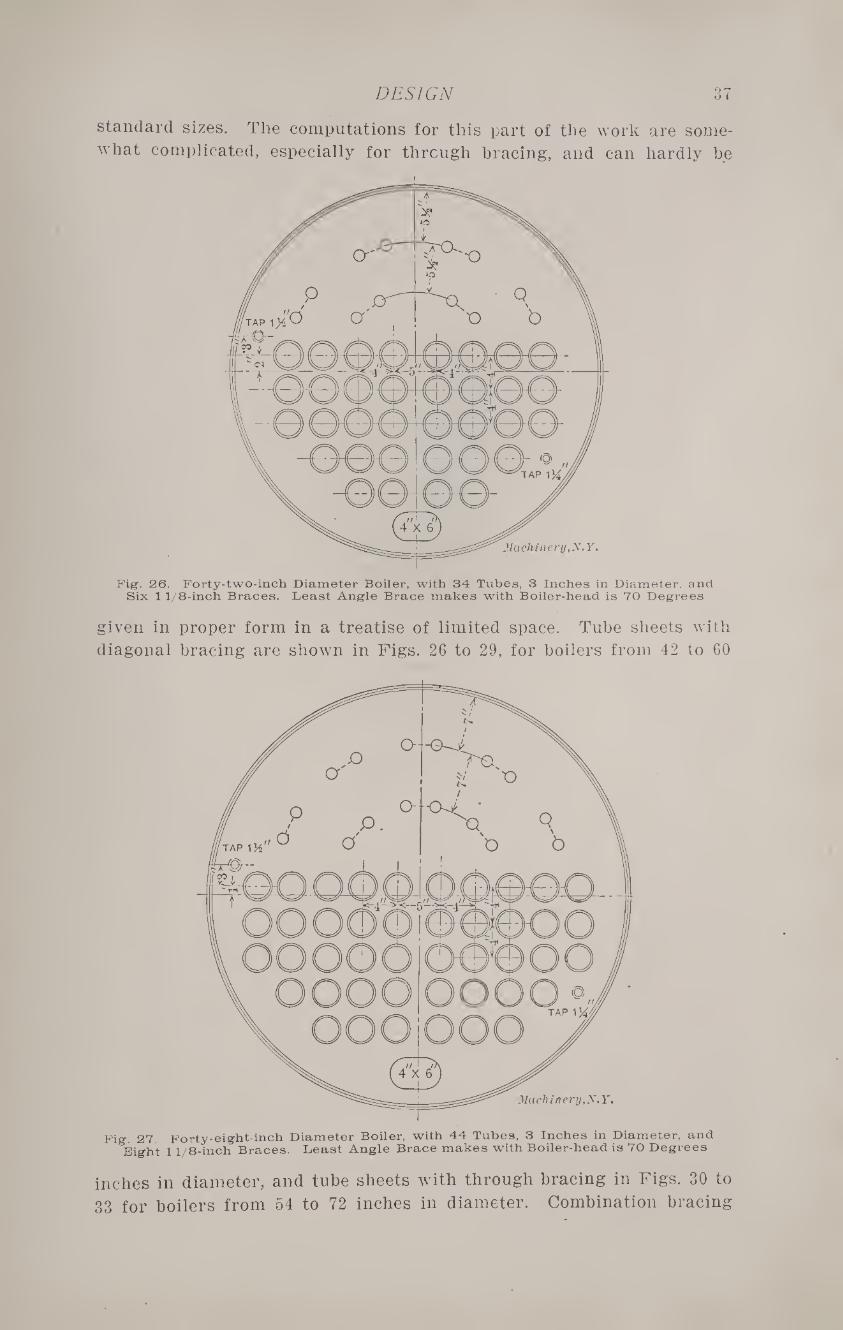
Fig. 26. Forty-two-inch Diameter Boiler, with 34 Tubes, 3 Inches in Diameter, and Six 11/8-inch Braces. Least Angle Brace makes with Boiler-head is 70 Degrees
given in proper form in a treatise of limited space. Tube sheets with
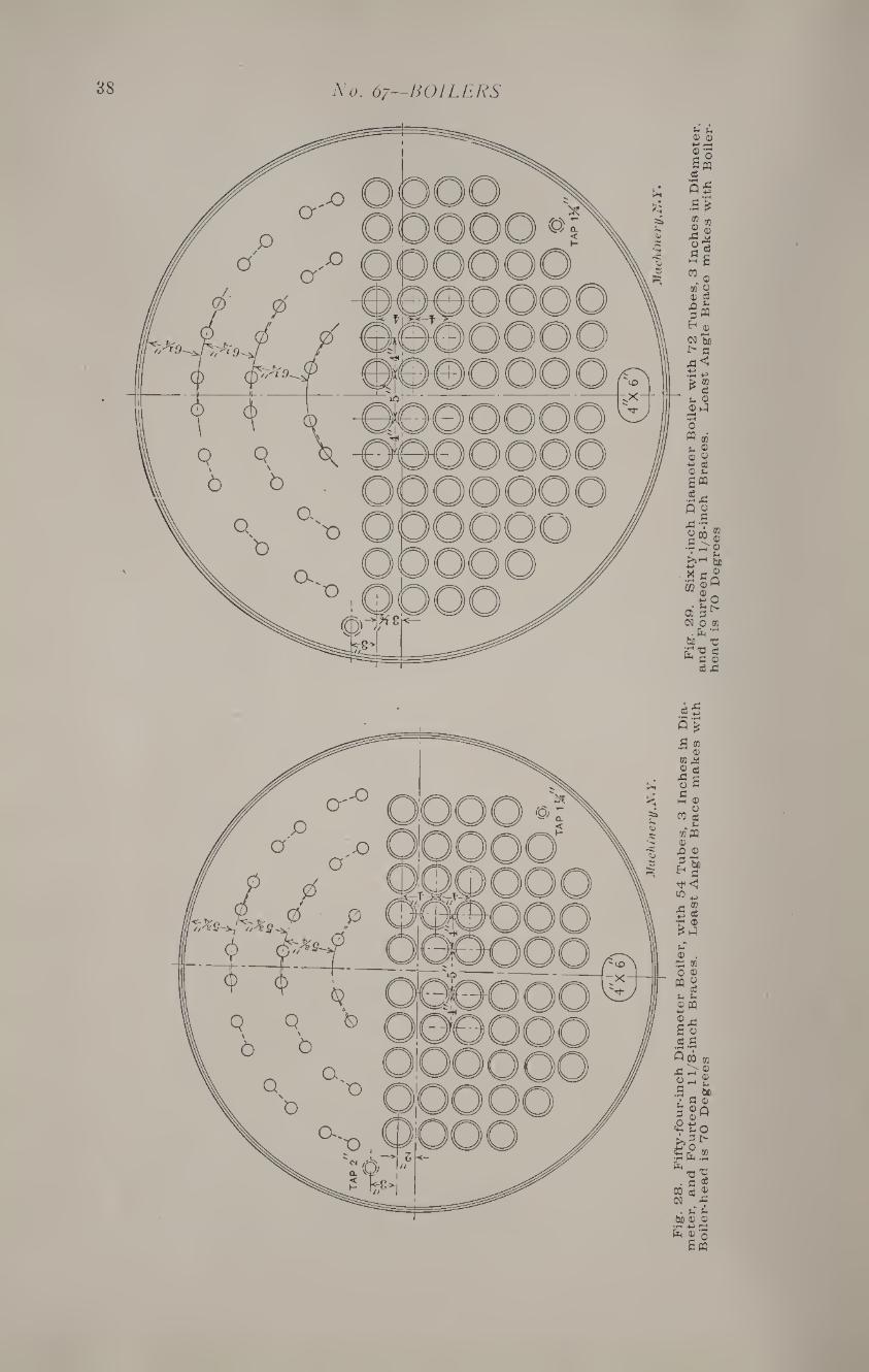
diagonal bracing are shown in Figs. 26 to 29, for boilers from 42 to 60
Fig. 27. Forty-eight-inch Diameter Boiler, with 44 Tubes. 3 Inches in Diameter, and Bight 11/8-inch Braces. Least Angle Brace makes with Boiler-head is 70 Degrees
inches in diameter, and tube sheets with through bracing in Figs. 30 to
33 for boilers from 54 to 72 inches in diameter. Combination bracing
No. 67—BOILERS
DFSIGN 39
40 No. 67—BOILERS
for boilers 54 and 60 inches in diameter can be made up by the use
of Figs. 28 and 30, for the first, and Figs. 29 and 31 for the second.
In doing this, the two upper through braces with their stiffening bars
may be omitted, and diagonal braces from Figs. 28 and 29 substituted
in their places. The tube sheets shown in Figs. 26 to 29, inclusive, are designed espe¬
cially for heating work, but are amply strong for pressures of 100
For 100 Pounds Pressure: Angle, 3% x 3 x 13-16 inch ; long flange riveted to head. Upper and lower bars, 7 x 2.67 x 0.57 inch channels. Diameter of rivets for channels and angle, 1 inch Diameter of stays, 1% inch. Ends upest to 2% inches. Diameter of washers, 6 inches. Thickness of washers, 1 inch.
For 150 Pounds Pressure : Angle, 3 x 3 x 1-2 inch ; long flange riveted to head. Upper and lower bars, 3% x 3 x 13-16 inch angles, two for each ; long flanges riveted to head. Rivets and washers, same as above. Diameter of stays, 2% inch. Ends upset to 2% inches.
pounds per square inch. The number and size of braces are given
directly below the illustration in each case. If pressed steel braces
are used, they should have a sectional area of at least 1 square inch at
the weakest point, and should be riveted to the shell and head with 2 « rivets at each end, not less than % inch in diameter. The length of
all diagonal braces should be such that the angle formed with the
head shall not be less than 70 degrees.
DESIGN 41
The tube sheets shown in Figs. 30 to 33, inclusive, are designed for
high pressure work, dimensions being given directly below the il¬
lustrations for working pressures of 100 and 150 pounds per square
inch. When combination bracing is used, as previously described, pres-
For 100 Pounds Pressure: Angle, 3% x 3 x 13-16 inch; long flange riveted to head. Upper and lower bars, 3% x 2y2 x 11-16 inch angles, two for each ; long flanges riveted to head. Diameter of rivets for angles, 1 inch. Diameter of stays, 1% inch. Ends up¬ set to 2% inches. Diameter of washers, 6 inches. Thickness of washers, 1 inch.
For 150 Pounds Pressure: Angle, same as above. Upper and lower bars, 3% x3x 13-16 inch angles, two for each; long flanges riveted to head. Rivets and washers same as above. Diameter of stays 2% inches. Ends upset to 2% inches.
sures should not be carried much above 100 pounds, unless additional
diagonal braces are added. Fittings
Boiler fittings include man-holes, hand-holes, nozzles, and brackets.
Three types of man-holes are showp in Figs. 34, 35, and 36. In the
first two, the frames, yokes and covers are of cast iron, while the
third is of pressed steel. A common form of cast iron hand-hole with
42 No. 67—BOILERS
plate and yoke is shown in Fig. 37. Standard man-holes are made 11
by 15 inches in size, of oval form. Hand-holes are commonly 4 by 6
inches in size. The tapered nozzle, shown in Fig. 38, is a good form for
high-pressure work as it offers less resistance to the flow of steam.
Fig. 34. Man-hole Design with Frame, Yoke and Cover of Cast Iron
Machinery .X. F.
* s
Straight nozzles are generally used on heating boilers and those car¬
rying moderate pressures.
A detail of the brackets commonly employed for supporting hori¬
zontal boilers is shown in Fig. 41, and the method of attaching them
Mremm
Machinery.X.Y
p "
Fig. 35. Another Type of Man-hole Design
to the boiler shell in Fig. 3. In the case of boilers of small and
medium size, two brackets are used on each side, but for those of
large size, it is customary to arrange them in pairs, four on each side,
as in Fig. 3. Manufacturers commonly have standard patterns for
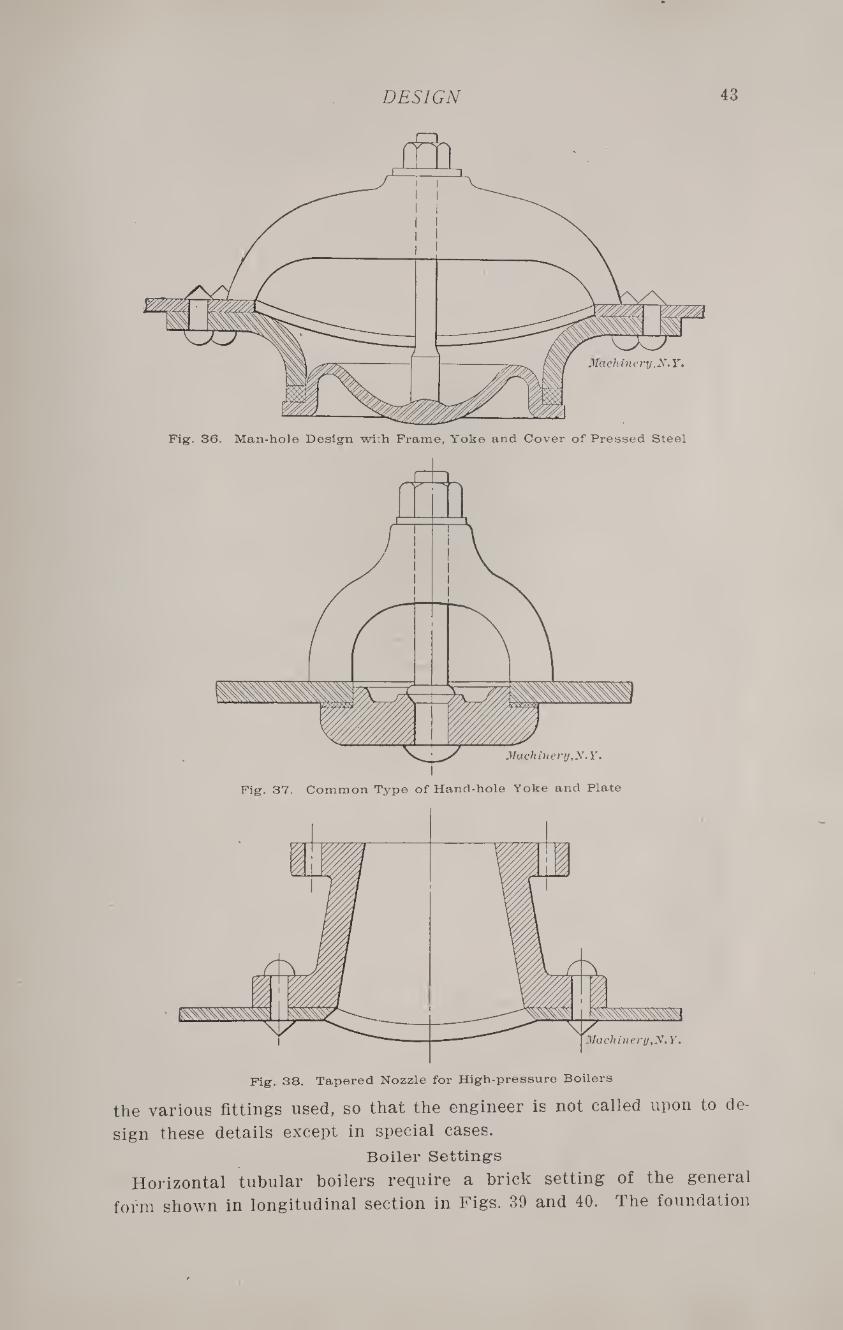
DESIGN 43
Fig. 36. Man-hole Design wirh Frame, Yoke and Cover of Pressed Steel
Fig. 38. Tapered Nozzle for High-pressure Boilers
the various fittings used, so that the engineer is not called upon to de¬
sign these details except in special cases.
Boiler Settings
Horizontal tubular boilers require a brick setting of the general
form shown in longitudinal section in Figs. 39 and 40. The foundation
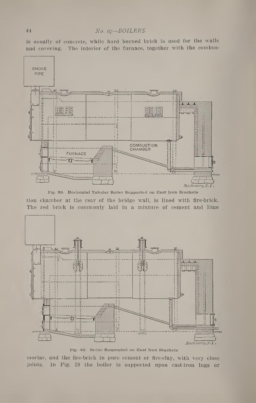
44 No. 67—BOILERS
is usually of concrete, while hard burned brick is used for the walls
and covering. The interior of the furnace, together with the combus-
Fig. 39. Horizontal Tubular Boiler Supported on Cast Iron Brackets
tion chamber at the rear of the bridge wall, is lined with fire-brick.
The red brick is commonly laid in a mixture of cement and lime
mortar, and the fire-brick in pure cement or fire-clay, with very close
joints. In Fig. 39 the boiler is supported upon cast-iron lugs or
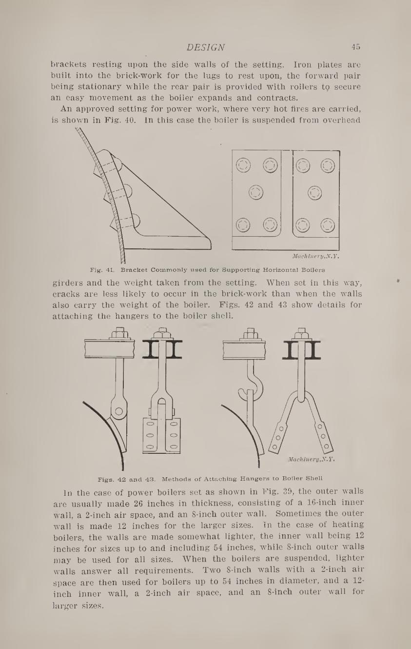
DESIGN 45
brackets resting upon the side walls of the setting. Iron plates are
built into the brick-work for the lugs to rest upon, the forward pair
being stationary while the rear pair is provided with rollers to secure
an easy movement as the boiler expands and contracts.
An approved setting for power work, where very hot fires are carried,
is shown in Fig. 40. In this case the boiler is suspended from overhead
Fig. 41. Bracket Commonly used for Supporting Horizontal Boilers
girders and the weight taken from the setting. When set in this way,
cracks are less likely to occur in the brick-work than when the walls
also carry the weight of the boiler. Figs. 42 and 43 show details for
attaching the hangers to the boiler shell.
Figs. 42 and 43. Methods of Attaching Hangers to Boiler Shell
In the case of power boilers set as shown in Fig. 39, the outer walls
are usually made 26 inches in thickness, consisting of a 16-inch inner
wall, a 2-inch air space, and an 8-inch outer wall. Sometimes the outer
wall is made 12 inches for the larger sizes. In the case of heating
boilers, the walls are made somewhat lighter, the inner wall being 12
inches for sizes up to and including 54 inches, while 8-inch outer walls
may be used for all sizes. When the boilers are suspended, lighter
walls answer all requirements. Two 8-inch walls with a 2-inch air
space are then used for boilers up to 54 inches in diameter, and a 12-
inch inner wall, a 2-inch air space, and an 8-inch outer wall for
larger sizes.
CHAPTER V
BOILER TESTING
The tests most commonly made on steam boilers are for steaming
capacity, and efficiency. The power, or steaming capacity, of a boiler
depends upon the weight of dry steam which it will evaporate in a
given time, without regard to the weight of fuel required. The effi¬
ciency takes into account the fuel consumption as well as the amount
of steam evaporated, and is the ratio of the heat utilized in the
process of evaporation to the total heat in the fuel burned. In making
a comparison of two boilers, the weight of dry steam in each case is
reduced to an equivalent evaporation from and at 212 degrees, the
quality of the steam being determined by the use of a calorimeter as
previously stated in Chapter I. The efficiency of the boilers should
be given due weight when comparing the operation of the two.
General Rules
Before starting a test, certain data should be obtained, and various
preliminaries attended to, as noted below:
1. —Measure and record the following dimensions: grate surface,
heating surface, smoke pipe, and chimney.
2. —Clean the boiler thoroughly of both soot and scale, and have the
grates and furnace walls free from clinkers.
3. —Thoroughly dry a sample of coal, and compare it volume for
volume with an undried sample, and determine the proportion of
moisture. For approximate tests, a pound of best anthracite coal may
be assumed to contain 14,000 T. U., and a pound of Cumberland coal
12,500 T. U. If an accurate efficiency test is desired, it should be made
with a standard coal whose heat of combustion is known, or a sample
may be sent to an expert for analysis.
4. —All tanks, scales, thermometers, gages, etc., used, should be
examined and checked for accuracy.
5. —Before starting a test, the boiler and chimney should be heated
to their usual working temperature. In case of a new plant, the fires
should be run for at least a week before making the test.
6. —All steam and water connections should be examined and made
tight, and the main steam pipe so graded that no condensation can
drain back into the boiler. If fed by an injector, the steam for operat¬
ing it should be taken from the boiler being tested.
In the accepted method of testing, steam is raised to the normal
working pressure, the fire drawn and all refuse removed from the ash¬
pit. A new fire is then started, a record being kept of the weight of
all fuel used for this purpose. At the end of the test the fire is again
drawn and the ash-pit cleaned as at the beginning.
TESTING BOILERS 47
In an alternate method the fire is allowed to burn rather low, and is
then thoroughly cleaned; the amount of coal left on the grate at this
time is carefully estimated. At the close of the test the fire should
be brought to practically the same condition as at the start. With
either method, the steam pressure and water level should be the same
at the beginning and close of the test, and should be maintained as
nearly uniform as possible throughout the run.
For simple tests which are carried on under regular working con¬
ditions the last described method is to be preferred. For accurate tests
the run should be continued for at least twenty-four hours, but for
approximate work a full day of eight or ten hours will give very good
results. The coal used during the test is usually weighed in barrels,
the net weight being accurately recorded, and any which is unused
at the end of the run being deducted from the total.
The feed-water may be measured by a meter, if the accuracy of this
has been tested by weighing the water which has passed through it
in a given time and the results compared with the reading of the
meter. If there is no meter, or if its accuracy has not been tested,
the water used during the test may be weighed in barrels. The
quality of the steam should be taken at frequent intervals during the
test; and the weight of feed water used, multiplied by the average
quality of the steam, will give the total weight of dry steam evaporated.
The temperature of the feed water is usually taken by means of an
oil-cup thermometer screwed into the feed pipe near the boiler. The
temperature of the feed water and the quality of the steam should be
taken once in fifteen minutes, if fairly uniform, and oftener if there
is considerable variation.
The chimney draft is measured in inches of water by means of a U-
tube, one end of which is connected with the chimney by means of a
rubber tube, and the other open to the atmosphere. The method of
working up the report is best shown by a practical example. •
Data
Heating surface, 2000 square feet.
Grate area, 40 square feet. Ratio of grate area to heating surface, 1 to 50.
Kind of fuel, anthracite coal.
Length of run, 10 hours.
Rated horsepower, 200.
From Observation
Average steam pressure, 100 pounds (gage).
Chimney draft, 0.2 inch water.
Temperature of feed water, 50 degrees F.
Pounds of coal burned, 6300.
Amount of moisture in coal, 5 per cent.
Pounds of refuse, 500.
Pounds of water fed to boiler, 63,000. Quality of steam from calorimeter, 98 per cent (average for test).
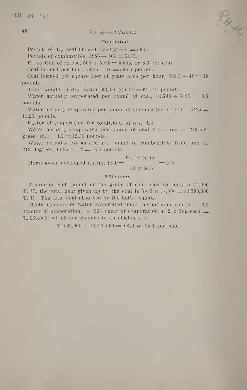
FEB 24 1911
48 No. 67—BOILERS
Computed
Pounds of dry coal burned, 6300 x 0.95 = 5985.
Pounds of combustible, 5985 — 500 = 5485.
Proportion of refuse, 500 -^ 5985 = 0.083, or 8.3 per cent.
Coal burned per hour, 5985 h- 10 = 598.5 pounds.
Coal burned per square foot of grate area per hour, 598.5 40 = 15
pounds.
Total weight of dry steam, 63,000 X 0.98 = 61,740 pounds.
Water actually evaporated per pound of coal, 61,740 -^- 5985 = 10.3
pounds.
Water actually evaporated per pound of combustible, 61,740 -r- 5485 =
11.25 pounds.
Factor of evaporation for conditions of test, 1.2.
Water actually evaporated per pound of coal from and at 212 de-
giees, 10.3 X 1.2 = 12.36 pounds.
Water actually evaporated per pound of combustible from and at
212 degrees, 11.25 X 1.2 = 13.5 pounds.
61,740 X 1.2 Horsepower developed during test =-:-= 215.
10 X 34.5
Efficiency
Assuming each pound of the grade of coal used to contain 14,000
T. U., the total heat given up by the coal is 5985 X 14,000 = 83,790,000
T. U. The total heat absorbed by the boiler equals:
61,740 (pounds of water evaporated under actual conditions) X 1.2
(factor of evaporation) X 966 (heat of evaporation at 212 degrees) =
71,569,000, which corresponds to an efficiency of
71,569,000 -r- 83,790,000 = 0.854 or 85.4 per cent.