Embed Size (px)
Citation preview
STATUS OF COLD CAVITY BEAM POSITION MONITOR FOR STF
A. Heo, Eun-San Kim, Kyungpook National University, Daegu, Korea Hayano Hitoshi, KEK, Ibaraki, Japan
Abstract Cold cavity BPM was developed to meet high position
resolution and bunch to bunch measurement time. It is designed based on re-entrant cavity and has Low-Q to achieve short signal decay time in L-band frequency with large aperture as 78mm. The beam test was performed to demonstrate position resolution at ATF main linac, which is operating with 1.6nC bunch charge, while BPM will be installed inside the ILC cryomodule with 3.2nC spacing 369ns like as ILC at STF. Stripline BPMs, ML2P and ML3P installed upstream and downstream of the BPM’s location respectively were used to predict its position. Reference cavity was optimized to use for synchronous detection. We had achieved ~340nm position resolution since position resolution was estimated due to limitation of system with noise, namely in case of ideal state. We will present configuration of beam test, procedure to measure position resolution and the result on the test. Furthermore, new design will be introduced to improve signal intensity and have heavy coupling.
INTRODUCTION
The ILC (International Linear Collider) consists of electron and positron linac beamline [1]. STF (Superconducting RF Test Facility, KEK, Japan) aim at realizing basic unit of the ILC linear accelerator with three cryomodules which is installed 8~9 nine-cell cavities, respectively [2].
L-band re-entrant cavity BPM is installed in every third cryomodule to monitor the beam orbit. Therefore this cavity BPM needs to operate in a cryogenic environment at 2K temperature same as in cryomodule. In order to acquire bunch to bunch signal, low cavity quality factor is required. The diameter of beam pipe aperture was decided as 78mm. HPR washable and cleansable structure is necessary. A few hundred nano-meters resolution for single pass is required [3].
Since cold model was fabricated, its resolution was measured using by simple electronics circuit such as BPF, diode, and amplifier. And then the ideal resolution was demonstrated with reference cavity, down convertor, and phase detector. In this paper we describe the results of measurement.
CAVITY BPMS
The cold model of re-entrant cavity BPM is shown by Fig. 1. The RF characteristics were measured by using network analyzer as shown in Table 1~3. Resonant frequency is 2.052GHz to avoid interference with acceleration cavity HOM. Averaged loaded Q value is low as 211, coupling constant, β, is 0.35 and the x-y isolation is -29.8dB.
Figure 1: Cold model cavity BPM.
Table 1: Transmission.
Port f(GHz) Δ f S21 QL
3-1 (S21) 2.052215 0.010170 0.396 202 3-1 (S12) 2.052252 0.010185 0.398 201 2-4 (S21) 2.052455 0.009390 0.363 219 2-4 (S12) 2.052538 0.009300 0.369 221
Table 2: Reflection.
Port f(GHz) dB S21 β0i βi
1 2.051900 -6.040 0.498 0.335 0.447 2 2.052395 -4.437 0.600 0.250 0.324 3 2.051877 -4.112 0.626 0.230 0.333 4 2.052425 -3.927 0.635 0.223 0.296
Table 3: Isolation
Port f(GHz) Isolation Port f(GHz) Isolation
1-2(S21) 2.052297 -28.1 1-2(S12) 2.052417 -28.0 2-3(S21) 2.052102 -29.6 2-3(S12) 2.051960 -29.5 3-4(S21) 2.052372 -32.5 3-4(S12) 2.052538 -32.4 4-1(S21) 2.052305 -29.3 1-4(S12) 2.052222 -29.3
____________________________________________
TUPC097 Proceedings of IPAC2011, San Sebastián, Spain
1236Cop
yrig
htc ○
2011
byIP
AC
’11/
EPS
-AG
—cc
Cre
ativ
eC
omm
onsA
ttri
butio
n3.
0(C
CB
Y3.
0)
06 Beam Instrumentation and Feedback
T03 Beam Diagnostics and Instrumentation
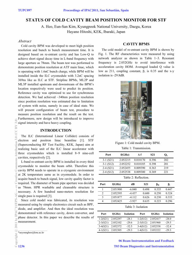
The reference cavity is used for synchronous detection as shown by Fig. 2. Its frequency was tuned to closer re-entrant cavity BPM (2.0495000GHz).
Figure 2: Reference cavity.
BEAM TEST OF COLD MODEL
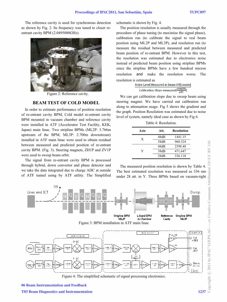
In order to estimate performance of position resolution of re-entrant cavity BPM, Cold model re-entrant cavity BPM mounted in vacuum chamber and reference cavity were installed in ATF (Accelerator Test Facility, KEK, Japan) main linac. Two stripline BPMs (ML2P: 3.766m upstream of the BPM, ML3P: 2.700m downstream) installed in ATF main linac were used to obtain residual between measured and predicted position of re-entrant cavity BPM. (Fig. 3). Steering magnets, ZH1P and ZV1P were used to sweep beam orbit.
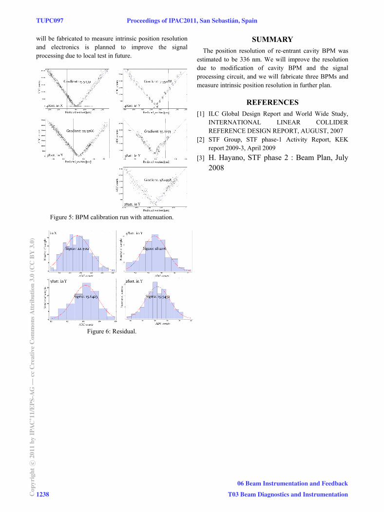
The signal from re-entrant cavity BPM is processed through hybrid, down convertor and phase detector and we take the data integrated due to charge ADC at outside of ATF tunnel using by ATF utility. The Simplified
schematic is shown by Fig. 4. The position resolution is usually measured through the
procedure of phase tuning (to maximise the signal phase), calibration run (to calibrate the signal to real beam position using ML2P and ML3P), and resolution run (to measure the residual between measured and predicted beam position of re-entrant BPM. However in this test, the resolution was estimated due to electronics noise instead of predicted beam position using stripline BPMs since the stripline BPMs have a few hundred micron
resolution and make the resolution worse. The
resolution is estimated as
We can get calibration slope due to sweep beam using
steering magnet. We have carried out calibration run along to attenuation usage. Fig 5 shows the gradient and the graph. Position Resolution was estimated due to noise level of system, namely ideal case as shown by Fig 6.
Table 4: Resolution.
Axis Att. Resolution
X 48dB 1441.15 38dB 960.324
Y 48dB 2398.48 38dB 471.647 28dB 336.118
The measured position resolution is shown by Table 4.
The best estimated resolution was measured as 336 nm under 28 att. in Y. Three BPMs based on vacuum-tight
Figure 3: BPM installation in ATF main linac
Figure 4: The simplified schematic of signal processing electronics.
Proceedings of IPAC2011, San Sebastián, Spain TUPC097
06 Beam Instrumentation and Feedback
T03 Beam Diagnostics and Instrumentation 1237 Cop
yrig
htc ○
2011
byIP
AC
’11/
EPS
-AG
—cc
Cre
ativ
eC
omm
onsA
ttri
butio
n3.
0(C
CB
Y3.
0)
will be fabricated to measure intrinsic position resolution and electronics is planned to improve the signal processing due to local test in future.
Figure 5: BPM calibration run with attenuation.
Figure 6: Residual.
SUMMARY
The position resolution of re-entrant cavity BPM was estimated to be 336 nm. We will improve the resolution due to modification of cavity BPM and the signal processing circuit, and we will fabricate three BPMs and measure intrinsic position resolution in further plan.
REFERENCES
[1] ILC Global Design Report and World Wide Study, INTERNATIONAL LINEAR COLLIDER REFERENCE DESIGN REPORT, AUGUST, 2007
[2] STF Group, STF phase-1 Activity Report, KEK report 2009-3, April 2009
[3] H. Hayano, STF phase 2 : Beam Plan, July 2008
TUPC097 Proceedings of IPAC2011, San Sebastián, Spain
1238Cop
yrig
htc ○
2011
byIP
AC
’11/
EPS
-AG
—cc
Cre
ativ
eC
omm
onsA
ttri
butio
n3.
0(C
CB
Y3.
0)
06 Beam Instrumentation and Feedback
T03 Beam Diagnostics and Instrumentation