Embed Size (px)
Citation preview

Start-up Dynamics ofTCP's Congestion Control and Avoidance Schemes
by
Janey C. Hoe
B.S. in Electrical Engineering and Computer ScienceUniversity of California at Berkeley, 1993
Submitted to the Department of Electrical Engineering and Computer Sciencein Partial Fulfillment of
the Requirements for the Degree ofMaster of Science in Electrical Engineering and Computer Science
at the
Massachusetts Institute of Technology
June, 1995
© Janey C. Hoe 1995
The author hereby grants to MIT permission to reproduce and todistribute publicly paper and electronic copies of this thesis
document in whole or in part.
.___.. /2
Signature of AuthorD tment fElectrical Engineering and Computer Science
May 26, 1995
Certified
by
Accepted by
Dr. David D. ClarkSenior Research Scientist, Laboratory for Computer Science
Thesis Supervisor
..................... \ esor Fr ic R. M orgenthalernt mmittee on Graduate Students
OF IIECHNOLOGY
JUL 1 71995LIBRARIES Barker Eng
Certified bv ~~~CI~ /j~p~ -U~i· · Gor A,


Start-up Dynamics ofTCP's Congestion Control and Avoidance Schemes
by
Janey C. Hoe
Submitted to the Department of Electrical Engineering and Computer Scienceon May 26, 1995
in partial fulfillment of the requirements for the degree ofMaster of Science in Electrical Engineering and Computer Science
Abstract
Over the years, Transmission Control Protocol (TCP) in the Internet protocol (IP)suite has become the most widely used form of networking between computers. Withthe recent developments in high-speed networking and applications that use TCP,performance issues in TCP are of increasing interest and importance. The perfor-mance (e.g. throughput, number of dropped packets, etc.) during the start-up epochis of particular concern, because an increasing number of applications use TCP forshort data transfers, which complete before TCP even settles into its steady-state be-havior. During this initial epoch, as TCP hunts for reasonable operating parameters,its congestion control and avoidance schemes display interesting transient dynamicsthat affect the performance.
One reasonable approach to examining such performance issues is to study and un-derstand the dynamics of current TCP implementations. Thus, this thesis makesobservations on the subtle congestion control and avoidance dynamics of one par-ticular implementation of TCP, U.C. Berkeley's BSD Net/2 release, with specificattention to the start-up epoch. Based on these observations, this thesis proposessome simple changes to this implementation to improve its performance during thestart-up epoch.
Thesis Supervisor: Dr. David D. Clark
Title: Senior Research Scientist, Laboratory for Computer Science
·I___I_*IPCI___·_U___I

Acknowledgments
I would like to thank my thesis advisor, Dave Clark, for his guidance and support and
for generously sharing his knowledge and ideas. I appreciate his patience while I tried
to find my way through this project. His intuition and enthusiasm about networking
and the social grace with which he delivers his ideas have been very inspiring. I
thank John Wroclawski, who has put a lot of time into helping me get started with
this thesis and giving me technical guidance along the way, for his support and for
many interesting, informative discussions on various technical, non-technical topics.
I also thank Karen Sollins for her support and for always being one of the best, most
resourceful person to turn to when I ran into problems of all kinds.
I sincerely thank AT&T Bell Labs and AT&T Foundation for opening many doors
of opportunity for me by giving me my first technical internship four years ago and
funding my graduate education through the GRPW Program now.
I thank my friends, especially the great people of the ANA group: Ye Gu, Oumar
Ondiaye, Lisa Trainor, Jeff VanDyke, and Bien Velez-Rivera. I thank my officemate,
Christopher Lefelhocz, for technical advice and for making everything more interest-
ing. I especially thank Tim Shepard for his work in his master's thesis, his xplot
program, his technical help, many rides to the grocery store, and many fun, interest-
ing conversations. And I thank Andrew Heybey and many others who contributed to
the implementation of the original Netsim simulator. In addition, I thank Riccardo
Gusella for his friendship, for believing in me, and for challenging my thoughts.
I thank Nathan Yee for embracing my rough edges and enriching my life with his
companionship. Finally, I thank my family for being supportive and accommodating.
Most of all, I am greatly indebted to my extraordinary parents, Nai Jea and Ling
Hwa Hoe, who have always unselfishly ranked my wellness and education as their top
priority and in the process of doing so, have quietly endured many hardships and
made many sacrifices.

Contents
1 Introduction 11
1.1 Motivation for This Thesis ........................ .. 11
1.2 Understanding TCP's Start-up DynamicsThrough Simulations ........................... 12
1.3 Organization of This Thesis ....................... .. 13
2 Related Work 14
2.1 Observation on TCP Dynamics ..................... 14
2.2 Congestion Control and Avoidanceon a Network .................... ............ 16
3 TCP: Points of Interest 18
3.1 Background on TCP, the Protocol .................... 18
3.1.1 A Brief Overview of TCP .................... 18
3.1.2 TCP's Self-Clocking Mechanism ................. 20
3.2 BSD Net/2 Implementation of TCP .................... 21
3.2.1 Implementation of the TCP Specification ............ 23
3.2.2 Slow Start and Congestion Avoidance .............. 24
3.2.3 Delayed Acknowledgment .................... 26
3.2.4 Fast Retransmits and Fast Recovery .............. 27
I'IIII~IIDAI~L~CU~·~~Y·~C-----·-··------

4 The Simulations:Environment and Methodology
4.1 The Simulator ............................
4.1.1 The Network Model and the Corresponding Components
4.1.2 A Connection
4.1.3 BSD Net/2 TCP Component .........
4.1.4 Network Topology and Parameters ......
4.2 Performance Metrics ..................
4.3 Reading the Graphs . . . . . . . . . . . . . . . . . . .
4.4 Limitations of the Simulations . . . . . . . . . . . . .
5 Observations on the Start-up Transients of the Nettion of TCP
5.1 Congestion Window....................
5.2 Delayed Acknowledgment ...............
5.3 Fast Retransmits ....................
5.3.1 Single Packet Loss ...............
5.3.2 Multiple Packet Losses ..............
5.3.3 False Fast Retransmits . . . . . . . . . . . . .
5.4 Damped Exponential Phase of the Slow Start . . . .
6 Simulation Parameters
6.1 Why Not Pick A Larger Buffer Size? . . . . . . . . .
6.2 Sensitivity of Results to SimulationParam eters .......................
.. ..... .. 29
. . . . . . . . . 30
.. ..... .. 31
. . . . . . . . . 32
. . . . . . . . . 34
/2 Implementa-
37
39
42
42
44
49
51
54
54
56
7 Implementation Suggestions for Better Performance
7.1 A Good Initial Value of ssthresh ....................
7.2 Recovery from Multiple Packet Losses ................ . .
7.3 Limiting the Output of Successive Packets ................
58
59
62
64
28
28
28
.. ..... .... .... .... ..... .. 29
i

8 Conclusions and Future Work 65
8.1 Summary of Results . .......................... ..... 65
8.2 Future W ork ...... ........................... ..... 66

List of Figures
3.1 Important TCP features in BSD releases .................. 22
4.1 Network topology used in the simulations ................. 30
4.2 An example of a detailed time-segment-number graph ....... . . . 33
4.3 An example of a time-segment-number graph for an entire 1-Mbytetransfer . . . . . . . . . . . . . . . . . . . . . . . . . . . . . . . .. . 33
4.4 An example of a congestion window graph ................ 34
5.1 Effect of the extra maximum segment size factor . . . . . . . . . . . 38
5.2 A blowup of the top graph in Figure 5.1. .................. 40
5.3 Effects of delayed acknowledgments .................... 41
5.4 An 1-Mbyte transfer (acknowledging every packet and eliminating the' factor) and its relevant events ..................... 43
5.5 Recovery from a single packet loss .................... . 45
5.6 The "grouping" effect after recovery from a single packet loss ...... 46
5.7 Multiple packet losses leading to a retransmission timeout ...... 47
5.8 False fast retransmit ........................... 50
5.9 Damped slow start ............................ 53
6.1 An 1-Mbyte transfer using a larger buffer size .............. 55
6.2 Parameter Sensitivity ........................... 57
7.1 An 1-Mbyte transfer using the original Net/2 TCP code. ........ . 59

7.2 The 1 Mbyte transfer using an estimated ssthresh value ....... 61
7.3 Recovery from multiple packet losses using the proposed mechanism . 63

List of Tables
5.1 False fast retransmit ........................... 50

Chapter 1
Introduction
This thesis studies the subtle start-up dynamics of one particular implementation of
Transmission Control Protocol (TCP), U.C. Berkeley's Net/2 release. Based on these
observations, this thesis proposes simple changes to this implementation to improve
its performance during the start-up epoch.
1.1 Motivation for This Thesis
Over the years, TCP, a reliable, connection-oriented stream transport protocol in the
Internet protocol (IP) suite, has become the most widely used form of networking
between computers[23]. Although some users complain about TCP's performance,
what the protocol may lack in performance, it compensates with its robustness. It
is able to hide failures and even bugs of the network and of the TCP implementa-
tions themselves. Because TCP achieves its primary function of reliable data delivery,
many application developers and users have not been very concerned with the details
of TCP's mechanisms and how they affect TCP's performance. However, with the
developments in high-speed networking and applications that use TCP, many per-
ceive an opportune time to improve current implementations of TCP and address
performance issues in TCP.

One paper that centers on such performance issues is the work of L. Brakmo,
S. W. O'Malley, and L. L. Peterson on TCP Vegas [3]. The initial focus of this
project was simply to reproduce the results of that paper in a simulator environment.
This original intent dictated the choice of the parameters and the topology used
in our simulations. Our preliminary simulation results showed interesting dynamics
within TCP's congestion control and avoidance schemes, especially during the start-
up epoch. Thus, our focus shifted into the goals of this thesis: (1) to examine
closely TCP's congestion control and avoidance dynamics that affect the start-up
performance and (2) to suggest implementation changes that may help TCP's start-
up performance.
1.2 Understanding TCP's Start-up Dynamics
Through Simulations
We have a strong interest in understanding TCP dynamics, because such understand-
ing is relevant to performance improvements. We are also interested in the complexity
of this seemingly simple protocol. Since the 1981 release of its specification [17], which
left many performance issues such as window size up to the implementors, implemen-
tations of TCP have been augmented with several performance-enhancing mecha-
nisms, such as congestion control, fast retransmission, and fast recovery [1, 11, 23].
With these mechanisms and their interactions, many will agree that the complexity
of TCP has made its detailed behavior very difficult to comprehend without close
scrutiny using simulations, emulations, or visualization tools.
Thus, the work of this thesis involves enhancing an existing network simulator,
Netsim [10], to examine one particular implementation, U. C. Berkeley's BSD Net/2
TCP. This thesis focuses on the start-up epoch, because TCP's performance (e.g.
throughput, number of dropped packets, etc.) during this epoch is important. In
particular, many of TCP's congestion control and avoidance dynamics occur dur-

ing this epoch as it hunts for reasonable operating parameters. With the increased
complexity and size of networks, this period of probing the network for operating
parameters is longer in duration. Moreover, a large number of applications, e.g. Tel-
net, FTP, Mosaic, etc., use TCP for short data transfers, which complete before TCP
settles into its steady-state behavior. Thus, the start-up epoch is a significant portion
of the duration of most data transfers over TCP connections.
1.3 Organization of This Thesis
Chapter 2 summarizes the work related to ours. Subsequently, in Chapter 3, we
briefly describe the TCP features and mechanisms that are of interest. In Chapter 4,
we discuss the simulator and the issues related to the simulations studied in this thesis.
Chapter 5 presents the results from the simulations and the observations of the start-
up dynamics of the Net/2 implementation of TCP. In Chapter 6, we evaluate the
relevance of the simulation parameters. Based on the observations in Chapter 5, we
suggest potential performance improvements during the start-up epoch in Chapter 7.
Finally, Chapter 8 draws conclusions and discusses future work.
Chapter 2
Related Work
Related work can be categorized into two main areas: (1) observation on the dynamics
of TCP and its congestion control schemes in particular and (2) network congestion
avoidance and control schemes in general.
This thesis differs in motivation from the work mentioned in Section 2.1 in that
this thesis focuses on the start-up dynamics of one specific implementation of TCP.
The work in Section 2.2 proposes general congestion avoidance and control schemes
that have a broader scope and intent than this thesis.
2.1 Observation on TCP Dynamics
Van Jacobson's important paper [11] defines his congestion avoidance and control
schemes, generally known as slow start. These schemes are now a essential part of
the TCP implementations. We refer to these schemes in Chapter 3.2.2.
Selective acknowledgments [2, 12, 13] is an extension to TCP that has been pro-
posed. Using selective acknowledgments, the receiver of data can inform the sender
about all the segments' that have arrived successfully, so the sender need retransmit
1In this thesis, segments and packets have different meanings. In particular, segments, whichcan have variable lengths, refer to the blocks of user data that TCP sends and receives enclosed ininternet datagram "envelopes". Such an "envelope", along with the segment it contains, is referredto as a packet.

only the segments that have been lost. This thesis proposes an alternative mechanism
to deal with multiple packet losses within one round-trip time of a TCP connection
in Section 7.2.
Shenker and Zhang [21] use simulations to make some observations about the
behavior of the congestion control algorithm in the 4.3-Tahoe BSD TCP implemen-
tation. They note and explain two main observations. First, packets from individual
one-way connections originating from the same host are separated into completely in-
dividual clusters, instead of being interleaved. Second, every connection loses a single
packet during each congestion epoch. The motivation of their paper differs from that
of this thesis in that their paper focuses on the steady-state behavior of the algorithm
and omits the initial start-up transients in their data set.
As an extension of the paper above, Zhang, Shenker, and Clark [28] examines the
dynamics of the same congestion control algorithm, but this time focusing on the
effects of two-way traffic. The paper makes two new observations: ACK-compression
and out-of-phase queue synchronization. Again, this paper only focuses on TCP's
steady-state behavior.
From simulations of TCP/IP network operations, Zhang and Clark [27] examine
and document the data traffic oscillation phenomena that have been observed both
in operational networks and in simulations. Mogul [16] shows how to observe in "real
life" some of the phenomena described in the previous work by analyzing traces of a
busy segment of the Internet and how to measure their frequency and their effects on
performance.
Brakmo and Peterson [3] propose an alternative implementation of the TCP spec-
ification, claiming better performance. The new implementation, TCP Vegas, com-
pares the measured throughput rate with an expected throughput rate (defined as
window size divided by the minimum of all measured round trip times) and uses this
information to determine changes in the congestion window. The implementation also
proposes other additions such as spike suppression, more accurate RTT calculations,

and a new mechanism for deciding when to retransmit. Danzig, Liu, and Yan [7]
evaluate the algorithms of TCP Vegas using live emulation.
Two papers point out various performance problems of some TCP implementa-
tions. First, in a paper available by ftp, Brakmo and Peterson [4] describe some prob-
lems in the BSD 4.4-Lite version of TCP and propose some fixes that may increase
the throughput. Some of the problems reported lie in header prediction, retransmit
timeout estimates, and acknowledgments. Second, Floyd [8] focuses on the problem
of Tahoe and Reno TCP implementations that result from invoking the fast retrans-
mit mechanism more than once in one round-trip time. This thesis provides some
simulation data to corroborate similar problems in the Net/2 TCP implementation
as well.
In another paper, Floyd [9] discusses the use of Explicit Congestion Notification
mechanisms in the TCP/IP protocol. In addition, Romanow and Floyd [20] inves-
tigate the performance of TCP connections over ATM networks with no ATM-level
congestion control and compare it to the performance of TCP over packet-based net-
works.
2.2 Congestion Control and Avoidance
on a Network
There are several proposed approaches for congestion control and avoidance. Ra-
makrishnan and Jain [18] propose a congestion avoidance scheme that uses one bit
in each packet as feedback from the network to adjust the amount of traffic allowed
into the network. The servers in the network detect congestion and set a congestion
indication bit on packets flowing in the forward direction. When the receiver detects
that the bit is set, it advertises a smaller window to the sender, even though it may
have ample storage space.

Jain's CARD (Congestion Avoidance using Round-trip Delay) [14] approach is
based on an analytical derivation of a socially optimum window size for a determin-
istic network. The window size is adjusted once every two round-trip delays (RTT).
If the product (current window size - old window size)(current RTT - old RTT) is
positive, the window size is decreased by one eighth. Otherwise, the window size
is increased by one maximum segment size. Therefore, the window changes during
every adjustment and oscillates around its optimal point.
Wang and Crowcroft's Tri-S scheme [24] is based on using the flattening of the
sending rate as an indication that the network is approaching congestion. Every
RTT, the window size is increased by one segment, and the achieved throughput
is compared to the throughput when the window was one segment smaller. If the
difference is less than one-half the throughput achieved when only one segment was
in transit, window is decreased by one segment. Throughput in this scheme is defined
by the number of bytes outstanding in the network divided by the RTT.
Wang and Crowcroft's DUAL algorithm [25] checks to see if the current RTT is
greater than the average of the minimum and maximum RTT's seen so far every two
round trip delays. If so, the scheme decreases the congestion window by one-eighth.
Keshav's Packet-Pair rate probing technique [15] sends two back-to-back segments
and determines an estimate of the available bandwidth from the delay between the
ACK's.
NETBLT [5, 6] is a high throughput transport protocol based on flow control by
rate. The protocol uses selective acknowledgments.

Chapter 3
TCP: Points of Interest
This chapter describes the salient aspects of the TCP protocol and of the particular
BSD Net/2 implementation of TCP. First, we give a brief overview of TCP. We then
point to a key mechanism of TCP, the self-clocking (using ACK's) mechanism. This
mechanism keeps data flowing on TCP connections and thus has an essential role in
congestion avoidance and control.
Next, we discuss a particular implementation of TCP, BSD Net/2. We briefly
frame the Net/2 release chronologically in the history of BSD networking code releases
and point out the key features that are implemented in Net/2 TCP.
3.1 Background on TCP, the Protocol
This section gives an overview of TCP, and points out important mechanisms of the
protocol.
3.1.1 A Brief Overview of TCP
Transmission Control Protocol (TCP) is a reliable connection-oriented stream trans-
port protocol in the Internet protocol (IP) suite. Its identifying features include

explicit and acknowledged connection initiation and termination, reliable, in-order,
unduplicated delivery of data, congestion control, and out-of-band indication of ur-
gent data. Details of the protocol specification are in [17].
TCP operates on top of the IP architecture. IP itself makes no guarantee to
deliver packets reliably. TCP provides a reliable byte stream with end-to-end flow
control by using checksums, sequence number, acknowledgments (ACK's), and win-
dows. Once the connection is established between end hosts, data is communicated
by the exchange of segments. The window dictates the amount of data a sender can
send. It indicates the allowed number of octets that the sender can transmit before
receiving further permission. Because the segments may be lost, to ensure reliable
delivery, TCP retransmits after a timeout. When segments are received, the sequence
and acknowledgment numbers and other information flags in the segments are used
to verify their acceptability and are also used to determine the next TCP state and
corresponding actions (e.g. send new data, retransmit data, close down connection,
etc.).
In the IP architecture, data from applications on the end hosts is passed to TCP
and then to the network. Data is transported by IP switches, which generally use first-
in-first-out queuing schemes'. When the aggregate queuing of packets from multiple
connections causes buffer overflow in the switches, packets are dropped. Based on the
assumption that packet loss caused by data corruption during transit, which results in
checksum test failure, is rare (much less than 1% of all the packet losses [11]), we can
infer from a packet loss that a packet has been dropped at a bottleneck switch, and
thus a packet loss can be used as an indication of congestion in the implementations.
TCP's use of ACK's to implement reliable data delivery builds into the protocol
a fundamental property, the self-clocking mechanism. We touch on this important
mechanism in the following subsection.
'The queuing schemes used in switches are evolving with recent developments.
3.1.2 TCP's Self-Clocking Mechanism
TCP's self-clocking mechanism is fundamental to keeping the data flowing on a con-
nection. In TCP, the receiver acknowledges data segments received, and these ACK's
trigger the sending of new data segments when they return to the sender, because
they advance the window. Thus, the ACK's can be viewed as a "clock signal" to
strobe new packets into the network. Thus, the protocol is "self-clocking", since the
ACK's can be generated no faster than data packets can get through the network. A
more detailed discussion on this is in [11].
Ideally, this mechanism can be exploited for congestion avoidance. Data packets
arrive at the receiver no faster than the rate of the bottleneck link bandwidth. If the
receiver's ACK's arrive at the sender with the same spacing, then by sending new
data packets at the same rate the sender can avoid overloading the bottleneck link.
Although the mechanism is subjected to distortion by ACK's that do not arrive with
the same spacing or ACK-compression [28], over a large time scale, the distortion is
transient. In any case, ACK-compression is not a significant factor within the scope of
this thesis. We raise this issue for completeness, but we will not offer further detailed
discussions.
The self-clocking mechanism is at the center of Jacobson's idea of "conservation
of packets" [11]. A connection is said to be in equilibrium if it is running stably with
a full window of data in transit. So, a connection in equilibrium is "conservative" if
a new packet isn't put into the network until an old packet leaves. To relate to the
self-clocking mechanism, since an ACK indicates that a packet has been received or
has left the network, it gives a good signal that a new packet can be injected. Such
a "conservative" connection would be robust in the face of congestion.
During the start-up epoch, the challenge for TCP is to reach the equilibrium
quickly without overshooting, with very little information available about the net-
work. These ideas will resurface later when we discuss simulator results, since they
are the basis of the congestion control and avoidance scheme in the particular TCP
implementation we used in the simulator.
Our simulation results will demonstrate that this mechanism is essential to the
basic operation and performance of TCP. In Section 5.3.1, the simulation results
show this mechanism at work. In contrast, in Section 5.3.2, the results indicate what
happens when the mechanism is disrupted by other features of the TCP implemen-
tations. For example, when faced with congestion, the congestion control scheme can
momentarily stop the sender from transmitting any more segments to avoid further
congestion. As a result, ACK's stop coming back, and no new packets can be clocked
out. Thus, the connection is temporarily "dried up". Once this is detected, the
self-clocking mechanism can be restored. However, such dry spells are damaging to
TCP's performance.
3.2 BSD Net/2 Implementation of TCP
This section describes some key features in the Net/2 TCP implementation 2 studied
in our simulations. We build an understanding of a set of terminology related to the
implementation, and the set will be used in the discussion of the results .
Figure 3.1 (adapted from [26]) frames the Net/2 release in a chronology of the
various BSD releases, indicating important additions of features with each release.
As seen in the Figure, the TCP code in the Net/2 release is functionally the same
as that of the better known TCP implementation, Reno. The releases shown on the
left side in the figure are publicly available source code releases, which contain all of
the networking code: the protocols, the kernel routines for networking interface, and
many of the applications and utilities.2From this point on, we refer to the Net/2 implementation as "the implementation".

4.1cBSD(1982)first release
4.2BSD(1983)first widely available
release of TCP/IP
BSD Networking SoftwareRelease 1.0(1989): Net/1
4.3BSD Tahoe(1988)slow start,
congestion avoidance,fast retransmit
14.3BSD Reno(1990)
fast recovery,TCP header prediction,
SLIP header compression,routing table changes
BSD Networking SoftwareRelease 2.0(1991): Net/2
4.4BSD(1993)multicasting
long fat pipe modifications
4.4BSD-Lite(1994)
Figure 3.1: A history of BSD releases and importantrelease. The diagram is adapted from [26].
TCP features added with each

3.2.1 Implementation of the TCP Specification
We briefly discuss the implementation of some key ideas in the TCP specification:
acknowledgment, reassembly, and retransmission timeout,
A well-known mechanism of TCP is that it acknowledges received data. A unique
sequence number is assigned to each octet of data transmitted, and when a segment
arrives, a receiver acknowledges the highest in-order sequence number seen so far.
(We later refer to this as snd-una3.) This implementation uses delayed ACK, and
this feature is describe in Section 3.2.3. However, for simplicity, in this subsection,
we assume that ACK's are not delayed. To illustrate how acknowledgments work,
suppose the sender sends several segments of size 512 bytes. (For simplicity, we
suppose that the first segment covers sequence numbers 1-512; the second covers 513-
1024, and so on.) Let's assume that the second segment is lost. So, at the receiver,
the reception of the first segment generates an ACK for sequence number 512. Since
the second segment is lost, when the third packet arrives, the receiver generates a
duplicate A K, an ACK that acknowledges the same sequence number as the last
ACK, for sequence number 512, the highest in-order sequence number seen so far.
The third segment is put on the reassembly queue, which caches out-of-order segments
for reassembly later when the missing packets, which may be retransmissions, arrive.
Until the second packet is received, each additional segment that arrives at the receiver
is cached in the reassembly queue, and a duplicate ACK is generated. Once the second
segment arrives, TCP uses that segment and the segments in the reassembly queue to
reassemble the longest in-order sequence of segments possible and generates an ACK
for the highest sequence number in that sequence.
As mentioned in the previous section, TCP uses retransmission to ensure reliable
data delivery. It specifies that if an ACK for a segment is not received within a timeout
interval, the segment is retransmitted. Because of the variability of the networks3Whenever possible, we use the terminology closest to that of the TCP specification or the code
of the implementation.

that make up an internetwork system and the various uses of TCP connections, this
retransmission timeout must be dynamically determined.
For this implementation, this timeout value is calculated using measured round-
trip delays of segments. Upon sending a packet, if no segment is currently being
timed, a round-trip timer is set. This round-trip timer has fairly coarse granularity;
it is incremented only every 500ms. It is stopped when the ACK for the segment
timed is received. A variable, smoothed round-trip time (SRTT), keeps track of an
approximation of the average of all the round-trip times measured so far, and another
variable, retransmission timeout (RTO), is constantly updated based on the RTT and
its variance. The details of these calculations can be found in [11] and the code.
The retransmit timer is set to the current RTO, and decremented every 500ms.
When an ACK is received, the retransmit timer is restarted with the latest, dynam-
ically calculated RTO. When the retransmit timer is decremented down to zero, we
call it a retransmission timeout.
3.2.2 Slow Start and Congestion Avoidance
We briefly discuss the mechanisms for congestion control and avoidance in this imple-
mentation. The schemes are generally known as slow start. More details and intuition
on this topic are in [11, 26].
Using these schemes, a sender is in one of two modes: slow start or congestion
avoidance. The two modes differ primarily in that the sending rate of data flow
increases more aggressively in the former mode than in the latter. A sender is in
slow-start mode under two conditions: (1) when it first starts transmitting data and
(2) immediately after a retransmission timeout. A sender shifts from the slow-start
mode to the congestion-avoidance mode at a certain threshold or immediately after
a fast retransmit, which is discussed in Section 3.2.4. Using the ideas discussed in
Section 3.1.2, the goal of slow-start mode is to quickly fill a empty "pipeline" until the

connection is approximately at equilibrium. At that point, the sender shifts in to the
less aggressive congestion-avoidance mode, which continues to probe the maximum
network capacity. Evidently, the choice of the threshold, which is essentially an
approximation of the equilibrium point of the connection, is key to the performance
of these schemes.
In practice, slow start and congestion avoidance are implemented together. To
implement these congestion control and avoidance schemes, the sender keeps track of
three variables: sndwnd, cwnd, and ssthresh. Snd.wnd is the window size adver-
tised from the receiver to sender. This advertised window size gives the sender an
estimate of the available window at the receiver. Cwnd is the congestion window,
and ssthresh is the slow-start threshold, which determines when a sender shifts from
the slow start mode into the congestion avoidance mode.
In slow-start mode, cwnd is initialized to one segment. Each time an ACK is
received, cwnd is incremented by one segment. At any point, the sender sends the
minimum of snd.wnd and cwnd. Thus, cwnd reflects flow control imposed by the
sender, and snd..wnd is flow control imposed by the receiver.
We see that following the description above, cwnd increases exponentially. To
be more specific, assuming that the ACK's are not delayed, the sender starts by
transmitting one segment and waiting for its ACK. When the ACK is received, cwnd
is incremented from one to two, and two segments are sent. When each of the two
segments is acknowledged, cwnd is incremented by one. The value of cwnd becomes
four. This exponential pattern continues similarly until cwnd becomes greater than
or equal to ssthresh. From then on, the sender shifts into the congestion avoidance
mode.
We note that in this implementation the ssthresh is initialized arbitrarily to the
maximum window size of the implementation, 65535. Later in the discussions of the
simulations, we will see that this high initial threshold leads to multiple packet losses
very soon after the connection starts. We also mention here that cwnd can never be

increased beyond the maximum window size of 65545.
In congestion avoidance mode, cwnd is incremented by (maZimu segment aize plusmaximum 8egment size each time an ACK is received4. This in effect additively increases8
cwnd in contrast with the exponential increase in the slow-start mode.
Congestion is indicated by a retransmission timeout or the reception of three dupli-
cate ACK's. When congestion is detected, ssthresh, which dictates when the sender
changes from slow-start mode to congestion-avoidance mode, is adjusted to one-half
of the current window (the minimum of snd-wnd and cwnd). This makes sense in
most cases, since the detection of congestion implies that the current threshold is
too high. The sender is too aggressive and thus is losing packets. The threshold is
lowered so that the sender shifts from exponential increase of its congestion window
to additive increase sooner in hope that the sender can slow down enough to avoid
congestion in the future.
3.2.3 Delayed Acknowledgment
In this implementation, TCP does not send an ACK the instant it receives a packet.
Instead, it delays the ACK, so that if there is data going the same direction as the
ACK, the ACK can be sent along, or "piggyback", with the data. An exception is
when out-of-order segments are received. In such cases, a duplicate ACK is generated
immediately. Even with the delayed acknowledgment mechanism, most of the time,
the receiver acknowledges every two segments in our simulations. This is because in
this implementation, when the available window at the receiver differs from the last
advertised window to the sender by twice the maximum segment size or more, the
receiver sends a window update, and ACK's (if any) can piggyback on this update.
In any case, no ACK is ever delayed for more than 200 msec in this implementation,4We refer to maximum segment size as the 1 factor for the rest of this document. This factor is a
known error, and it should be left out in future implementations [26]. In Section 5.1, we show somesimulation results that demonstrate why the factor is a problem.

since every 200 msec, a timeout takes place, and an ACK is generated if any is waiting
to be sent.
3.2.4 Fast Retransmits and Fast Recovery
The fast retransmit mechanism, described below, allows earlier detection of a missing
segment. Based on the duplicate ACK's, it makes an educated prediction about
which segment is missing. Without this mechanism, the sender would have to wait
for a long retransmission timeout, which is on the order of seconds, before it would
detect that a segment was lost. Under the fast recovery mechanism, the sender enters
the congestion-avoidance instead of the slow-start mode after a fast retransmit. We
discuss the implementation details of the two mechanisms below. To get the above
events to occur, the code manipulates various variables. These details can be seen
later in the seemingly strange variations in the graphs of the simulation results.
Upon receiving three duplicate ACK's, the fast retransmit mechanism deduces
that a segment has been lost. TCP assumes that the missing segment starts with
a sequence number immediately after the number acknowledged by the duplicate
ACK's, and the missing segment is retransmitted.
So, TCP first lowers ssthresh to half of the window size to avoid future conges-
tion. It then retransmits the missing segment. This is accomplished by adjusting
the snd nxt to that sequence number and closing down cwnd to one segment and
calling tcpoutput(). After the output is done, cwnd is readjusted to be ssthresh
plus one segment, and sndnxt is readjusted to the highest sequence number that
is outstanding so far on the connection (sndmax). This is so that the sender can
continue to send new data. The fast recovery mechanism refers to the way cwnd and
ssthresh are adjusted so that the sender enters the congestion-avoidance mode after
a fast retransmit.

Chapter 4
The Simulations:Environment and Methodology
This chapter describes the simulations. We first define the network model used in the
simulator, Netsim. We then discuss the necessary modifications to Netsim to conduct
the simulations presented in the following chapters. After an overview of the simple
network topology and parameters used, we point to some performance metrics. We
then discuss how to read the graphs of the simulation results. Finally, we evaluate
the limitations of the simulations.
4.1 The Simulator
4.1.1 The Network Model and the Corresponding Compo-
nents
The packet-by-packet, event-driven simulator is based on the model that a computer
network consists of an interconnected set of communication and switching compo-
nents. The communication components, such as ethernet and point-to-point links,
are characterized by bandwidth and delay. Networks like the internet make no guar-
antee to deliver packets reliably, and this is modeled in the simulator with the error

probability parameter in a point-to-point link component. However, for the simula-
tions in this thesis, to isolate the effect of TCP mechanisms, the probability is set to
zero. A switching component is characterized by its speed, processing delay, size of
input queues, and size of output queues. The switching components in the simulator
use the simple first-in-first-out queuing algorithm in the input and output queues,
and when the buffer overflows, the latest arriving packet is dropped.
4.1.2 A Connection
The network model described supports end-to-end communication through TCP con-
nections. A connection is established through three other components in the simu-
lator: the host component, the TCP component, and the user component. The host
component simulates the end hosts on which a TCP may reside, and it is connected
to the network fabric. The TCP component is associated with the end host com-
ponent and contains a particular implementation of the TCP algorithms. The user
component represents a user process, communicating over the network using a TCP
connection.
4.1.3 BSD Net/2 TCP Component
We introduced a new TCP component to the existing Netsim simulator. To create
this TCP component, we made minor modifications (which do not affect the behavior
of TCP) to the actual BSD Net/2 code to conform with the simulator environment
and requirements. This is the TCP component we used to produce the simulations
results in Chapter 5. The TCP component used for the results in Chapter 7 is also
based on this component with the implementation changes we propose.

4.1.4 Network Topology and Parameters
For all the simulations in this paper, we use a very simple topology shown in Fig-
ure 4.1. The buffer size of each switch is 10 packets. The segment size for transfer is
1024 bytes, and the maximum window size of the connection is 50 segments (51200
bytes). We transfer 1 Mbyte across a simple one-way TCP connection. We then graph
the simulation data using the graphical method modeled after [22]. This method is
explained briefly in Section 4.3.
10 Mbps 1600 Kbps 10 MbpsHost 1 Switch I Switch 2 Host 2
50 msdelay
Figure 4.1: Network topology used in the simulations
The parameters chosen may limit the relevance of the results to real situations.
For example, a more reasonable number for the buffer size parameter, may be thebandwidth-delay product of the bottleneck link (pack dwidth x dela ), which is 20,
in our case. More discussion on this is in Section 6.1, after we have had a chance
to look at some simulations. We picked a smaller buffer size, 10, which may have
led to more loss events. However, since this thesis is a part of the results obtained
from a attempt to reproduce Figure 6 in [3], our simulations use the same topology
and parameters as the experiments conducted in that paper. Another point is that
although this thesis does look at some performance issues, the focus is on TCP's
start-up transient behavior, i.e. how TCP reacts when congestion emerges. Since
such behavior occurs over a wide range of parameters, as long as the parameters are
within the range, the exact values of the parameters used is not of utmost importance.
In most cases, varying the parameters within the range only varies the timing and
duration of such behavior. Simulation results using other parameters will be organized
and presented in a later paper.

4.2 Performance Metrics
As mentioned before, although the focus of this thesis is not completely on perfor-
mance issues, we briefly list some important measures for the performance of a TCP
congestion control and avoidance schemes [19]:
* Control stability:
1. reliable detection of congestion
2. robustness to noise
3. low parameter sensitivity
4. appropriate sensitivity to transient congestion, e.g. bursts and synchro-
nization between flows.
* Timely response to changes in network utilization
* Efficiency: not a lot of unused bandwidth in the network but also no "abused"
bandwidth, e.g. excessive, unnecessary retransmission of data.
* Low delay, high throughput
* Control parameters not constrained by link speeds and network sizes
* Distributed control
* Fairness: identical source requirements should get approximately the same
bandwidths.
* Reasonable buffering requirement in switches
* Reasonable implementation
Of course, some of the above are conflicting goals that require algorithms to make
tradeoffs to reach a delicate balance. These measures give a guideline of how to
evaluate congestion control and avoidance schemes. Also, we want to keep these

guidelines, as well as the "conservation of packets" principle, in mind, when proposing
changes to TCP implementations.
4.3 Reading the Graphs
The simulation results are presented in two types of graphs: time-segment-number
graphs and simple graphs tracing the congestion window parameter of a TCP con-
nection. Both types of graphs show data collected from the sender's perspective.
The graphic convention used in the time-segment-number graphs is similar to that
developed in [22]. To make these graphs, we converted sequence numbers into seg-
ment numbers' to make the graphs more readable and the discussions simpler. We
occasionally draw circles around the regions of interest in the graph.
In a time-segment-number graph such as the one in Figure 4.2, the x axis represents
time, and the y axis represents segment numbers. Each small vertical line segment
with arrows (in the lefmost circled region) at the ends represents a segment sent at
that time. The length of a small vertical lines give an indication of the length of the
segment represented. There are two lines that bound the small vertical line segments:
the bottom one indicates the last acknowledged segment number or snd-una, and the
top one indicates sndwnd plus snd_una at any particular time. Small tick marks on
the bottom bounding line (in the rightmost circled region) indicates that a duplicate
ACK has been received.
In Figure 4.3, we show another time-segment-number graph. The figure displays
the same information for an 1-Mbyte transfer. Because of the lack of resolution, this
figure does not show many details. However, we occasionally show a picture like this
to display more general information about the transfer.
1We make the simplifying assumption that the segment number of a segment is the closest integerto the quotient of the highest sequence number in that segment divide by the maximum segmentsize, 1024 bytes.

segment number
100
80
60
40
0.75 0.8 0.85 0.9 0.95tih
Figure 4.2: An example of a detailed time-segment-number graph
segment number1000
800
600
400
200
1ne (secs)
2 4 6time (secs)
Figure 4.3: An example of a time-segment-number graph for an entire 1-Mbyte trans-fer

In a congestion window trace such as the one in Figure 4.4, the x axis represents
time and the y axis represents the size of the congestion window, cwnd, in bytes. The
small crosses show changes in the value of ssthresh.
cwnd (bytes)
60000
40000
20000
N
0 10time (secs)
Figure 4.4: An example of a congestion window graph
4.4 Limitations of the Simulations
As indicated in [7], simulations have their limitations, since they eliminate the "noise"
and the "randomness" in real networks. So, some behavior in simulations may not be
observed in real networks, and some situations in real networks may not be present in
a simulator. However, a useful characteristic of the simulation environment is that it is
a controlled environment. Various effects and behavior can be isolated by controlling
the setup topology or simulation parameters. Also, the simulator allows easy access to
any part of the complete information of all network traffic. This advantage aids in the
analysis of data and is useful in the process of testing various hypothesis. Therefore,
simulations can be a good initial approach to examine various networking issues.
Despite the limitations of simulations, our observations on TCP's dynamics pre-
sented in the next chapter are in fact in real networks. [22] shows many TCP traces
.J ir
k;/
l 10

of real networks, and many of the phenomena we observe in Chapter 5 can be easily
found in those traces.

Chapter 5
Observations on the Start-upTransients of the Net/2Implementation of TCP
Because many applications use TCP for short data transfers, the performance of TCP
(e.g. throughput, number of dropped packets, etc.) during the start-up epoch of a
TCP connection is of particular interest to some users. In this chapter, we document
some interesting observations on the start-up transients of a 1-Mbyte transfer over a
one-way Net/2 TCP connection simulated in the Netsim simulator [10]. Some of the
phenomena have been briefly discussed in other sources [4, 3, 8, 26].
We first look at the effects of increasing congestion window by more than one
segment every round-trip (an additional factor of maximum segmentsize is added per
acknowledgment) in the congestion-avoidance mode in Section 5.1. In Section 5.2,
we point out the impact of acknowledging pairs of packet, instead of every packet,
in changing the shape and the rate of the sending patterns during the exponential
slow-start mode. In Section 5.3, we discuss fast retransmits in Net/2 TCP. More
specifically, in the case of a single packet loss, fast retransmit works well. We also
note a "grouping" effect in the sending pattern following the recovery by a fast re-
transmit. We explain why it often does not work, i.e. it still needs to wait for a
retransmission timeout to recover from multiple losses during one round-trip time.
We also observe that false fast retransmits can occur during the exponential slow-
start mode following a retransmission timeout. In Section 5.4, we examine the effect
of a group of nonsequential packet losses, caused by bottleneck buffer overflow, lead-
ing to the damping of the exponential expansion of the congestion window during the
slow-start mode.
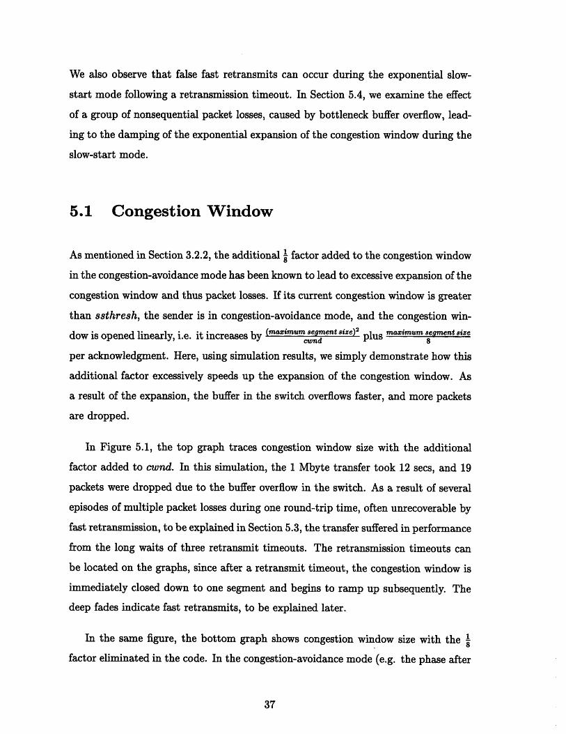
5.1 Congestion Window
As mentioned in Section 3.2.2, the additional factor added to the congestion window
in the congestion-avoidance mode has been known to lead to excessive expansion of the
congestion window and thus packet losses. If its current congestion window is greater
than ssthresh, the sender is in congestion-avoidance mode, and the congestion win-
dow is opened linearly, i.e. it increases by (maximum segment size) 2 plus maximum segment size
per acknowledgment. Here, using simulation results, we simply demonstrate how this
additional factor excessively speeds up the expansion of the congestion window. As
a result of the expansion, the buffer in the switch overflows faster, and more packets
are dropped.
In Figure 5.1, the top graph traces congestion window size with the additional
factor added to cwnd. In this simulation, the 1 Mbyte transfer took 12 secs, and 19
packets were dropped due to the buffer overflow in the switch. As a result of several
episodes of multiple packet losses during one round-trip time, often unrecoverable by
fast retransmission, to be explained in Section 5.3, the transfer suffered in performance
from the long waits of three retransmit timeouts. The retransmission timeouts can
be located on the graphs, since after a retransmit timeout, the congestion window is
immediately closed down to one segment and begins to ramp up subsequently. The
deep fades indicate fast retransmits, to be explained later.
In the same figure, the bottom graph shows congestion window size with the I
factor eliminated in the code. In the congestion-avoidance mode (e.g. the phase after

60000
40000
20000
60000
40000
20000
n0
5 10
5 10
time (secs)
time (secs)
Figure 5.1: Effect of the extra mai,,m segment size factor added to the congestion
window with each acknowledgment: the top graph traces congestion window size
during the 1-Mbyte transfer on the TCP connection, and the bottom graph shows
the congestion window size with the macimum segment size factor eliminated.the conestionwindow ize wih the mximum 8 emtsiefcoelined
cwnd (bytes)
0cwnd (bytes)

time 3 sec), the congestion window is opened by only one segment per window, and
packet loss does not occur after time 3 sec. In this case, the transfer only took 8.85
seconds, and experienced 1 retransmit timeout and only 13 packet losses.
We point out some details of interest in Figure 5.2, which is a blowup of the top
graph of Figure 5.1. The deep fades in the congestion window (e.g. at times 1.15
sec, 1.37 sec, and 2.78 sec on the bottom graph) indicate that fast retransmit was
activated at those times. We also that at those times, the ssthresh is reduced in
half. For a description of the adjustment of cwnd and ssthresh during that epoch,
see Section 3.2.4. With each additional duplicate ACK that is received, indicating
another packet is cached in the reassembly queue on the receiver side, the congestion
window on the sender side is opened up by one maximum segment size to account
for each packet cached on the receiver side to conserve the number of packets in
transit on the network. When a non-duplicate ACK is finally received, the inflated
congestion window is retracted to the current ssthresh value, accounting the drops
(in the circled regions) around times 1.3 sec and 1.47 sec. At time 2 sec on the same
graph, a retransmit timeout occurred. As a result, the congestion window dropped
to one maximum segment size, and began to open up with slow start again.
5.2 Delayed Acknowledgment
This section briefly discusses the effects of delayed acknowledgment, specifically in
the exponential increase of slow start. In this phase, an ACK of in-order segments
triggers more segments to be sent. The number of segments triggered is determined
by the number of segments that were just acknowledged plus one more segment (since
the congestion window is increased by one segment per ACK).
In Figure 5.3, we show the effects of delayed acknowledgment on the sending
pattern. To isolate this effect, we left out the 1 factor described in the previous
section in the code for the simulations in this section.

cwnd (bytes)
60000
50000
40000
30000
20000
10000
0.5 1 1.5 2 2.5time (secs)
Figure 5.2: A blowup of the top graph in Figure 5.1.
Without delayed ACK's, every ACK received acknowledges 1 segment and trig-
gers two additional segments to be sent. However, with delayed ACK, segments are
acknowledged in pairs (as explained in Section 3.2.3), so every ACK for two segments
received triggers three segments to be sent. As seen in the top graph in contrast
to the bottom graph, the exponential expansion of the congestion window is slower
when ACK's are delayed. The reason for the difference is that every ACK indicates
that a packet has been received by the receiver. Whereas this is true if the receiver
acknowledges every packet, in this implementation, with delayed ACK's, every ACK
actually acknowledges two packets.
Evidently, acknowledging every packet allows the "pipe" to be filled more quickly.
However, this aggressiveness does not automatically translate into higher throughput,
because acknowledging every packet expands the congestion window faster. Such ex-
pansion leads to buffer overflow and thus packet losses. As we will see in Section 5.3),
the sender must wait for retransmit timeouts, since multiple losses in one round-trip
time may not be recoverable by fast retransmit,

segment number
80
60
40
20
00.2 0.4 0.6 0.8
segment number time (secs)
80
60
40
20
00.2 0.4 0.6 0.8
time (secs)
Figure 5.3: Effects of delayed acknowledgments during the slow-start mode: the topgraph shows slow start with delayed acknowledgments, and the bottom graph showsthe more familiar exponential slow start with every packet acknowledged.
To compare the performance, using delayed ACK's, the 1 Mbyte transfer took 12
seconds and experienced 3 retransmit timeouts and 19 packet losses. On the other
hand, acknowledging every packet allows more speedy expansion of the congestion
window in the exponential of slow start. However, the same transfer took 12.8 sec,
since it suffered from 5 retransmit timeouts and 40 packet losses. We note the tradeoff
here. Although acknowledging every packet allows the sender to open up the conges-
tion window faster and thus to pump segments into the network faster, the sender
also loses more packets as a result of the aggressiveness.
We note that this result may be sensitive to the buffer size chosen. Because of
time constraint, we leave this issue as a part of future work.
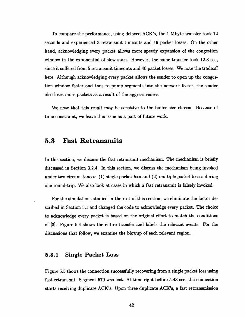
5.3 Fast Retransmits
In this section, we discuss the fast retransmit mechanism. The mechanism is briefly
discussed in Section 3.2.4. In this section, we discuss the mechanism being invoked
under two circumstances: (1) single packet loss and (2) multiple packet losses during
one round-trip. We also look at cases in which a fast retransmit is falsely invoked.
For the simulations studied in the rest of this section, we eliminate the factor de-
scribed in Section 5.1 and changed the code to acknowledge every packet. The choice
to acknowledge every packet is based on the original effort to match the conditions
of [3]. Figure 5.4 shows the entire transfer and labels the relevant events. For the
discussions that follow, we examine the blowup of each relevant region.
5.3.1 Single Packet Loss
Figure 5.5 shows the connection successfully recovering from a single packet loss using
fast retransmit. Segment 579 was lost. At time right before 5.43 sec, the connection
starts receiving duplicate ACK's. Upon three duplicate ACK's, a fast retransmission

Single packetloss recovered
2 4 6time (secs)
Figure 5.4: An 1-Mbyte transfer (acknowledging every packet and eliminating the 1
factor) and its relevant events
segment number1000
800
600
400
200
I

of segment 579 is invoked, and the congestion window size is reduced. Right before
the fast retransmission occurred, the connection has a congestion window of size
say old_cwnd, and therefore, oldcwnd segments are outstanding. In the bottom
graph, we see that with each duplicate ACK that continues to come in after the fast
retransmit, the congestion window is opened by one packet. At time 5.52sec, we
see that the congestion window is opened to the value oldcwnd. As the congestion
window continues to open, the connection is able to have more segments outstanding
and send new segments. At time right before 5.6 sec, an ACK for a large number of
segments, including segment 579, is received. This ACK causes the inflated congestion
window (to account for cached segments at the receiver side) to be retracted to
ssthresh, and the sender enters the congestion-avoidance mode as a result of the fast
recovery mechanism.
In Figure 5.6, we make the observation that the group of segments sent between
5.52 sec and 5.6 sec triggers the ACK's to come back in a similar pattern, triggering the
next group of packet to be sent out in a similar pattern, and so on. This "grouping"
effect becomes less obvious after 6.2 sec, as the pipeline is being filled and the ACK's
are coming in continuously. This effect is a good demonstration of TCP using the
acknowledgments as a self-clocking mechanism.
5.3.2 Multiple Packet Losses
In this section, we show that multiple losses during one round-trip may not be re-
coverable by the fast retransmit mechanism, and thus the connection must wait for a
retransmission timeout. We show one particular case in Figure 5.7. As seen in the fig-
ure, the large congestion window at time right before 0.7 sec allows a burst of closely
spaced packets into the network. At the bottleneck switch, the buffer overflows, since
the sender pumps the packets into the network at twice the speed at which the switch
is able to drain the buffer. Every other packet sent during that epoch overflows the
buffer and is lost.

segment number
660
640
620
600
580
560
5.4 5.6cwnd (bytes) time (secs)3UUUU
40000
30000
20000
10000
5.3 5.4 5.5 5.6time (secs)
Figure 5.5: The connection recovers from a single packet loss after a fast retransmit.
- - -- --

segment number
800
700
600
5.5 6 6.5time (secs)
Figure 5.6: The "grouping" effect during the recovery phase after a fast retransmittriggered by a single packet loss

segment number
100
80
60
40
Fast retransmit
0.8cwnd (bytes)
50000
40000
30000
20000
10000
1 1.2 1.4 1.6time (secs)
0.8 1 1.2 1.4 1.6time (sees)
Figure 5.7: As a result of multiple packet losses, fast retransmit did not work here.The sender has to wait for a retransmit timeout. The bottom graph shows thecorresponding congestion window size.

Segment number 51 is the first segment lost, and we see in the graph that around
the time right before 0.83 sec (in the circled region), the sender receives a duplicate
ACK acknowledging segment number 51. At this point, the sender is not able to
send any further since a full window of segments is outstanding. As time proceeds, a
group of closely spaced duplicate ACK's, triggered by the large surge of segments sent
earlier, is received. On the third duplicate ACK, segment 51 is fast retransmitted,
and this segment is acknowledged at time right before 1 sec.
As mentioned before, every other segment is lost starting with segment num-
ber 51. So, segment 53 is lost as well and needs to be retransmitted. Only two
mechanisms can cause a retransmission to occur: (1) a fast retransmission and (2) a
retransmission timeout. Note the value of the congestion window right before the last
fast retransmission is 51200 bytes, which is the maximum window size. The surge
of segments the sender transmits before 0.83 sec triggers the duplicate ACK's seen
between time 0.83 sec and 1 sec. When the fast retransmission occurs, the congestion
window is reduced to approximately half. (Recall from Section 3.2.4.) With each
duplicate ACK the sender receives, it is able to open the congestion window by one,
as seen in Figure 5.7. However, since the sender is not allowed to have more than
maximum window size of data outstanding, it cannot send any more segments until
non-duplicate ACK's comes in. Without any further transmission, no further ACK's
can be triggered, and thus fast retransmission cannot be used to retransmit segment
53. The only other way for retransmission to occur is to wait for the retransmission
timeout, which finally occurs at time 1.5 sec.
The underlying issues of this episode are (1) the initial value of ssthresh, which
allowed the sender to clock out a large surge of packets in exponential slow-start
mode leading to multiple packet losses and (2) the failure of fast retransmit and
recovery to recover the lost packets. The result is that the sender must wait for the
retransmission timeout, which drastically reduces the performance. The first issue
results, because the arbitrary initial value of ssthresh, 65535, is too high. With such
a high threshold, the sender aggressively increases its sending rate even though it may

have already saturated the bottleneck queues leading to the multiple losses.
The other issue is the failure of fast retransmit and recovery mechanisms to recover
multiple packet losses. In this case, the two mechanisms interfere with TCP's self-
clocking property as discussed in Section 3.1.2. In the face of possible congestion, the
two mechanisms performed their function of limiting the congestion window to avoid
further network congestion. However, until the multiple packet losses are recovered,
each new packet sent only triggers duplicate ACK's. So, once the sender has sent
out the full window of data, it comes to a halt waiting for non-duplicate ACK's. The
problem occurs when the sender stops sending new data, and no new data can be
acknowledged. During this dry spell of its fundamental clock signal (the non-duplicate
ACK's), the self-clocking mechanism breaks down, and the sender sits idle waiting
for the only other way to recovery, the time-consuming retransmission timeout.
5.3.3 False Fast Retransmits
In some cases, false fast retransmits can occur. We observe a particular case at time
1.95 sec (in the circled region) in Figure 5.8. In this figure, the sender is in the
exponential slow-start mode, immediately after a retransmission timeout to recover
from an episode of multiple packet losses. As explained in the Section 5.3.2, right
before the epoch shown in the figure, the sender pumps a continuous surge of packets
into the network, overflowing the buffer in the switch. As a result, every other packet
in that surge of packets is dropped at the switch as overflow. More specifically,
segments, numbered 51, 53, 55, 57, 59, and so on (every other packet up to packet
99) are lost. When the receiver receives out of order segments (segments 52, 54,
56, etc.), it stores them in the reassembly queue until the missing packets come in.
Since the fast retransmit is only able to recover a single segment, segment number
51, shown in Figure 5.7, a retransmission timeout occurs.
To explain Figure 5.8, we tabulate the beginning of the recovery process from the
sender's perspective in Table 5.1.

segment number
120
100
80
60
1.5 1.6 1.7 1.8 1.9time (secs)
Figure 5.8: False fast retransmit
Time (sec) I segments Sent ACK's Received
1.5 Segment 53 is retransmittedThe retransmission of segment 53at time 1.5 sec leads to an ACKof two segments: segments 53 and
1.61 54. The receiver acknowledges seg-ment 54 as well, since segment 54is already cached in the reassemblyqueue.
1.61 -Segments 55 and 56are retransmitted
The retransmission of segment 55leads to an ACK of two segments:
1.73 segments 55 and 56, since segment56 is already cache in the reassem-bly queue.The retransmission of segment 56
1.74 at time 1.61 sec leads to aduplicateACK of segment 56.
Table 5.1: False fast retransmit

The above pattern continues similarly. Following the pattern, we see that the
retransmission of a segment that was not lost, i.e. it is already cached at the receiver,
generates a duplicate ACK. We see that around time 1.97 sec, the retransmission
of a group of segments that are cached at the receiver leads to a series of duplicate
ACK's and thus a fast retransmit ( in the circled region). We call this a false fast
retransmit, since the mechanism is activated even though there is no segment loss.
False retransmits result from the interaction of the reassembly queue at the receiver
and the fast retransmit mechanism. In this case, the false retransmit mistakenly forces
the sender to go into the less aggressive congestion-avoidance mode, when there is
really no congestion. Such false fast retransmit degrades the performance.
In the same circled region, we also note a large spike right before the false retrans-
mit. This spike is due to the large ACK that arrived, which acknowledged most of
the outstanding segments. We discuss this further in Section 5.4.
5.4 Damped Exponential Phase of the Slow Start
The exponential phase of the slow start is designed so that the window opens up
quickly to fill the "pipe" and probes the network capacity. As shown in Section 5.2,for exponential expansion of the congestion window, each segment transmitted should
be acknowledged individually. However, we observe in Figure 5.8 (which captures the
slow-start mode after a retransmission timeout) and Section 5.3.3 that even though
the delayed acknowledgment mechanism is purposely turned off, because of the seg-
ments cached in the reassembly queue at the receiver, each segment retransmitted
does not produce an individual ACK.
Thus, immediately after a retransmission timeout, the exponential slow-start
mode is "damped". The magnitude of this effect can be seen by the comparison
shown in Figure 5.9. Both graphs show about 0.8 sec of transfer. The top graph
shows the exponential slow-start mode at the beginning of the connection. The bot-
tom graph shows the damped slow-start mode after a retransmission timeout. In the

same amount of time, approximately twice as much data is transferred during the
exponential slow-start shown in the top graph, compared to the bottom graph.
In the bottom graph, we also see more complicated sending pattern since during
this phase, the connection is still trying to recover lost segments. The large ACK
at around 1.93 sec occurs, because the segments retransmitted at around 1.82 sec
repaired the "holes" missing on the reassembly queue of many segments. Once those
"holes" are filled, the receiver is able to ack the entire sequence of the segments on
the reassembly queue. The large ACK also generates a large spike of segments that
are sent. Such closely spaced transmissions can lead to lost segments, depending on
the relative size of cwnd and the buffer. We discuss this issue briefly in Chapter 7.
We also see the false fast retransmission as discussed in Section 5.3.3.

segment number
80
60
40
20
0
segment number
120
100
80
60
0.2 0.4 0.6
1.6 1.8 2
Figure 5.9: The top graph shows the exponential slow-start mode atof the connection. The bottom graph shows the damped slow-startretransmission timeout
2.2time (secs)
the beginningmode after a
time (secs)
Chapter 6
Simulation Parameters
After the discussion of the simulation results, one important question is how sensitive
are the results to the parameters and topology used. We question whether the specific
setup we used contributed to the particular loss events in the simulations.
In Section 6.1, we discuss the relevance of the buffer size in the switch. We note
that the same loss events still occur even with a larger buffer size. However, we also
observe that the exact timing and dynamics of the congestion control and avoidance
mechanisms are sensitive to simulation parameters. We illustrate this in Section 6.2
using the parameter round-trip delay as an example.
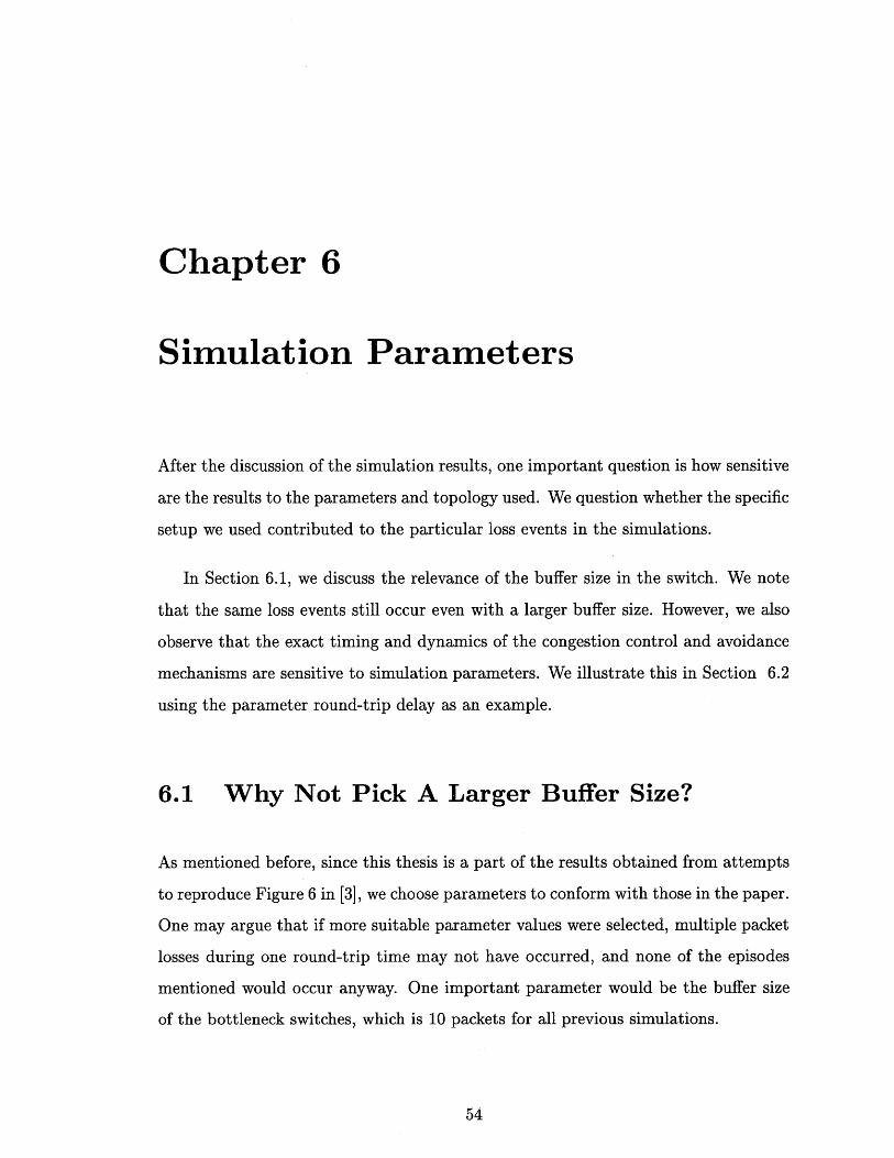
6.1 Why Not Pick A Larger Buffer Size?
As mentioned before, since this thesis is a part of the results obtained from attempts
to reproduce Figure 6 in [3], we choose parameters to conform with those in the paper.
One may argue that if more suitable parameter values were selected, multiple packet
losses during one round-trip time may not have occurred, and none of the episodes
mentioned would occur anyway. One important parameter would be the buffer size
of the bottleneck switches, which is 10 packets for all previous simulations.

To explore how the buffer size can affect the start-up dynamics, we examine an-
other set of simulations using a more reasonable number for the buffer size, 20. We
choose this number, since it is the bandwidth-delay product. Figure 6.1 shows the
same 1 Mbyte transfer using a buffer size of 20 in the switches. We observe the same
time-critical episode, i.e. a surge of segments being sent followed by the failure of fast
retransmit to recover from the multiple packet losses.
segment number1000
800
600
400
200
02 4 6
time (secs)
Figure 6.1: The transfer using a larger buffer size, 20, in the bottleneck switch.
This result is expected, since the episode really results from the surge of segments
being sent closely spaced such that the packets overflow the buffer in the bottleneck
switch. When the connection starts, ssthresh (the threshold at which the sender
changes from slow start to congestion avoidance) is arbitrarily set at the maximum
value, which is 65535 bytes in our case. This means that the congestion window opens
up exponentially until it reaches 65535 bytes. This large initial value of ssthresh
allows congestion window to open up quickly, but so quickly that a large surge of
closely-spaced packets are sent. As the "pipe" is being fed beyond its capacities,
packets have to be dropped.

6.2 Sensitivity of Results to Simulation
Parameters
Although in the previous section we found that the same loss events occur even with
a larger buffer size in the switch, in many other respects, we note that the exact
behavior of TCP's congestion mechanisms is sensitive to the parameters used.
To illustrate, in Figure 6.2, we show three traces of the congestion window for an
1-Mbyte, one-way transfer using a link with three slightly different one-way delays.
As seen in the figure, the slight change in the delay translates into very different
timing of the variations in the congestion window.
From this perspective, we find reproducing exactly other's TCP results difficult,
since the differences in the TCP implementations used, the methodologies, the models
and assumptions about the network, and the setup parameters can all contribute to
varying behavior.

cwnd (bytes)
60000
40000
20000
cwnd (bytes)
60000 1
40000
20000
cwnd (bytes)
60000
40000
20000
2 4 6
'I
2 4
time (secs)
Figure 6.2: From top to bottom, the graphs shows the trace of congestion window ofa 1 Mbyte transfer using a link with a one-way delay of 45 ms, 50 ms, and 55ms.
time (secs)
time (secs)
|
|
I
... ... ....
-
1

Chapter 7
Implementation Suggestions forBetter Performance
In Chapter 5, we made some observations on the start-up dynamics of TCP. To
improve TCP's performance during the epoch, it is useful to review the observations
and note the episodes of events that was time-critical. Figure 7.1 illustrates well
the critical path. The figure is a time-segment-number graph of an 1-Mbyte transfer
using the original Net/2 TCP code without any changes. It doesn't show any details,
but clearly we can see the time-consuming episodes of a surge of packets being sent,
leading to multiple packet losses and an unsuccessful attempt to recover those packets
using fast retransmission. With each of those episodes, the end result is the long wait
for the retransmit timeout, which is shown in the figure as the flat portion of the
graph during which the sender is not able to send any segments.
To deal with these episodes, there are two simple approaches: (1) curtail the surge
of packets that lead to multiple packet losses and (2) change the fast retransmit mech-
anism so that it may help the connection recover from multiple packet losses during
one round-trip time and thus reduce the need to wait for the retransmit timeouts.
The first approach can be implemented by finding a good initial value of ssthresh,
and the second requires a more aggressive attempt to recover lost segments.
We discuss these approaches below, and we show some initial simulation results.
We also mention briefly a way to deal with the large spike in the circled region of

segment number
1000
800
600
400
200
2 4 6 8 10 12time (sec)
Figure 7.1: An 1-Mbyte transfer using the original Net/2 TCP code.
Figure 5.8. These approaches give us a basis for future work on TCP performance
during the start-up epoch.
7.1 A Good Initial Value of ssthresh
From the previous section, we see that the initial value of ssthresh is critical. One
way to avoid the large surge of packet that leads to multiple packet losses is to pick
a lower ssthresh. A lower ssthresh would allow the congestion window to open
exponentially, aggressively up to ssthresh and then open additively (one segment per
window), probing the capacity of the "pipe" instead of overfeeding it. However, if
the initial ssthresh is set too low, the performance suffers. The congestion window
prematurely switches to the additive increase mode. As a result, although there is no
packet loss, the sender is sending so slowly that the transfer takes significantly longer.
So, we need to find a good estimate of the threshold at which the sender is closely

approaching the full network capacity and thus should slow down and probe the
remaining capacity. An example of such estimate would be the bandwidth-delay
product. We now have the problem of how to estimate the bandwidth and the round-
trip delay. Below, we discuss one simplified way to estimate this value. We show some
preliminary results, and we plan to improve on the method to obtain this estimate.
As mentioned in Section 3.1.2, data packets, which are sent closely spaced, arrive
at the receiver at the rate of the bottleneck link bandwidth. If the receiver's ACK's
arrive at the sender with approximately the same spacing, using the ACK's and the
time at which they arrive, we can calculate an approximation of the bandwidth. The
round-trip delay can be approximated by timing one segment, reading the timestamp
upon sending the segment and reading the timestamp again once the ACK for the
segment is received. We can then calculate the bandwidth-delay product. We set the
ssthresh to the byte-equivalent of this product.
In Figure 7.2, we show the simulation results from initializing ssthresh with
bandwidth-delay product. First, we timed the SYNC segment, the first segment
transmitted by a sender for synchronization between the receiver and the sender, to
get an approximation of the round-trip delay. Once the connection is established, the
bandwidth is calculated by using the least-squares estimation on three closely-spaced
ACK's received at the sender and their respective time of receipt. (This is similar
to the Packet-Pair algorithm in [15].) The resulting estimate, 20 or 20480 bytes, is
expectedly accurate. As a result, we see a very smooth transfers without retransmit
timeouts, since the good guess of the initial ssthresh value prevented the episodes of
the surge of packets that led to multiple packet losses. The occasional single packet
loss is effectively recovered by the fast retransmit mechanism.
The estimation method works well for our transfer, since our topology is simple
and involves only one unilateral transfer. In reality, we may not be able to obtain
an estimate as good or as quickly. Also, we need to take into account more sample
points, and use the statistical average instead just using the value of a single sample.
A part of our future work involves developing the estimation further.

segment number
1000
800
600
400
200
n1 2 3 4 5
time (secs)Figure 7.2: An 1-Mbyte transfer initializing the ssthresh with the byte- equivalentof bandwidth-delay product

However, even if the resulting estimate is higher than the "right" value, it would
be better than the arbitrary maximum value of 65535, which allows the sender to open
the congestion window too aggressively and leads to many packet losses. Admittedly,
on the other hand, if the estimate is too low, the sender may end up being too
conservative, and the resulting performance can be worse than having to lose multiple
packets and waiting for a retransmit timeout to recover. This is an issue we have to
address in future work.
7.2 Recovery from Multiple Packet Losses
In the event that multiple packet losses occur, Section 5.3 shows that the sender runs
out of enough duplicate ACK's to activate a fast retransmit (recall that it takes three
duplicate ACK's to activate it) for each of the packet losses, and ultimately has to wait
for a retransmit timeout. To recover from multiple packet losses, a more aggressive
fast retransmit algorithm is needed. We propose a change to the fast retransmit
mechanism so that it may recover from multiple packet losses more effectively.
There are two parts to the change once the fast retransmit mechanism is acti-
vated. First, in an attempt to keep the "flywheel" going, with every two duplicate
ACK's we receive, we force out a new segment with sequence number snd_nxt. In
the second part, we take notice of the highest sequence number sent before the fast
retransmission, call it highestseq. We define the fast retransmit phase as the time
between when we first invoke the fast retransmission upon three duplicate ACK's and
when the segment with sequence number highest-seq is finally acknowledged.
Assuming that the segment fast retransmitted is the only segment lost, the sender
expects the ACK of that segment retransmitted to acknowledge all segments up to
highestseq. Therefore, if the sender see an ACK for sequence number m less than
highestseq, the sender has a very good indication that the segment with the sequence
number m is lost as well. So, instead of waiting for three duplicate ACK's to activate

a fast retransmit, we retransmit the segment starting with the sequence number m
immediately. As long as we are in the fastretransmitphase, we repeat this algorithm
until we have seen the ACK for the segment with sequence number highest-seq. At
that point, we have recovered from the multiple packet losses during the round-
trip time. We demonstrate the new mechanism in the simulation results shown in
Figure 7.31.segment number
100
80
60
40
0.8 0.9 1 1.1 1.2 1.3time (secs)
Figure 7.3: Recovery from multiple packet losses using the proposed new fast retrans-mit mechanism and setting ssthresh initially to the estimate of the bandwidth-delayproduct.
Using this algorithm, it takes n round-trip time to recover n packet losses. How-
ever, in a typical connection, the number of packet losses per round-trip delay is
expected to be small. In addition, in the time it takes to wait for a retransmission
timeout (about 1 sec) in the previous simulations, the new mechanism can recover
up to 10 lost packet without waiting for a timeout, since round-trip-delay is 100ms.
Thus, the new mechanism offers a performance improvement. The mechanism can1Note that the mechanism can be more aggressive, i.e. update highest seq with each transmission
during the fast retransmit phase. We will address this in future work.

work even better if combined with setting the ssthresh to bandwidth-delay product,
as mentioned in the previous section. Setting ssthresh to a good estimate of the
bandwidth-delay product reduces the number of packets that overflow the buffer in
the first surge of packets sent, and thus, the new mechanism would have less packets
to recover.
As mentioned before in Section 2.1, this mechanism is an alternative to selective
acknowledgments. One may argue that selective acknowledgment is more effective and
efficient in the recovery of multiple packet losses. This may be true in some cases.
However, selective acknowledgment relies on the receiver, while the new mechanism
described above offers a way to deal with multiple packet losses from a unilateral,
sender's perspective. In addition, whereas the new mechanism is consistent with
the current TCP specification, implementing selective acknowledgment may require
changing the original specification of TCP. Comparatively, the new mechanism is
much simpler to implement, yet it offers reasonable performance improvement.
The concept of a fast retransmit phase can also be used to fix the problem of
false fast retransmits as pointed out by [8]. Since duplicate ACK's that acknowledge
segments from the same window as the segments from a previous fast retransmit are
not an indication of continued congestion, the sender can ignore all duplicate ack's
as long as it is in the fast retransmit phase.
7.3 Limiting the Output of Successive Packets
As mentioned in Section 5.3.3, during the recovery of multiple packet losses, a large
ACK can trigger a sudden surge of segments to be sent as shown in the circled region
of Figure 5.8. This sudden surge may lead to further loss of segments. One way to deal
with this problem is to limit the number of segments TCP can output successively in
such a situation. We leave the analysis of this issue for future work.

Chapter 8
Conclusions and Future Work
We briefly summarize the results from this thesis, and we discuss further extensions
to this work.
8.1 Summary of Results
This thesis makes some interesting observations on the start-up transients of Net/2
implementation of TCP. From the effects observed, results, and we plan to improve
on the method to obtain this estimate we realize the complexity of the interactions
between the different mechanisms in TCP. We also observe the importance of the
"conservation of packets" in the network [11] from all the subtle effects observed.
Ultimately, we need to keep the pipeline moving, since only by sending packets, can
ACK's be triggered, and only ACK's in turn can trigger more packets to be sent.
By learning from the dynamics noted, we make two simple proposals that may help
TCP's performance during the start-up epoch. The first involves making an educated
guess of a good ssthresh value in the hope of avoiding the large spike of packets that
leads to multiple packet losses seen in the simulations. The second proposes a slightly
more aggressive mechanism to recover from multiple packet losses.

We also learned about simulations. We realized that some results are very sensitive
to the parameters and topology used, whereas others are less sensitive and are based
more on the fundamental mechanisms in the protocol studied. Distinguishing the two
is important when comparing the performance of two implementations. One imple-
mentation may perform better than the other because of the particular setup used
and not necessarily because of the fundamental mechanism in that implementation.
8.2 Future Work
One important part of our future work is simulating with other parameters and topolo-
gies. This will give us an opportunity to observe other dynamics and issues. In this
thesis, to isolate the effects, we only studied a single, unilateral connection. However,
simulations of multiple two-way connections would provide more insight, which will
help us to refine and develop our suggested changes.
As mentioned before, we realize that simulations have limitations. An interesting
extension to this work would be to move the experiments on to real networks.
We note that TCP is very dependent on its self-clocking property. An interesting
question to investigate would be whether a different clocking signal can lead to better
performance. So, one topic to explore is a rate estimator that clocks out segments at
a "suitable rate". For instance, if we are able to estimate a reasonable rate to pump
packets into the network and keep packets in transit during the period between the
time period 0.85 sec and 1 sec in Figure 5.7, the ACK's returning would have been
able to trigger additional fast retransmits to avoid the long wait for the retransmis-
sion timeout. This may improve the performance during the start-up epoch. Perhaps,
using such a rate estimator, we could have avoided the multiple packet losses alto-
gether. In addition, we observe that the TCP phenomena described in this paper
are discrete in nature and arise from interactions between independent mechanisms.
A continuous rate estimator, which decides when segments are to be sent, may help
connections to start up more smoothly and suffer from less loss events.
Bibliography
[1] R. Braden. Requirements for internet hosts - communication layers. Request forComments 1122, DDN Network Information Center, SRI International, October1989.
[2] R. Braden. T/TCP-TCP extensions for transactions functional specification.Request for Comments 1644, DDN Network Information Center, SRI Interna-tional, July 1994.
[3] L. S. Brakmo, S. W. O'Malley, and L. L. Peterson. TCP Vegas: New techniquesfor congestion detection and avoidance. In Proceedings of the ACM SIGCOMM'94, pages 24-35, August 1994.
[4] L. S. Brakmo and L. L. Peterson. Performance problems in BSD4.4 TCP. Byanonymous FTP at cs.arizona.edu.
[5] D. D. Clark, M. L. Lambert, and L. Zhang. NETBLT: A bulk data transferprotocol. Request for Comments 998, DDN Network Information Center, SRIInternational, March 1987.
[6] D. D. Clark, M. L. Lambert, and L. Zhang. NETBLT: A high throughputtransport protocol. In Proceedings of the A CM SIGCOMM '88, pages 353-359,August 1988.
[7] P. B. Danzig, Z. Liu, and L. Yan. An evaluation of TCP Vegas by live emulation.Technical Report 94-588, USC Computer Science Department, 1994.
[8] S. Floyd. TCP and successive fast retransmits. By anonymous FTP at ee.lbl.gov.
[9] S. Floyd. TCP and explicit congestion notification. ACM Computer Communi-cation Review, 24(5):10-23, October 1994.
[10] A. Heybey. The network simulator. Technical report, MIT, September 1990.
[11] V. Jacobson. Congestion avoidance and control. In Proceedings of the ACMSIGCOMM '88, pages 314-329, August 1988.

[12] V. Jacobson and R. Braden. TCP extensions for long-delay paths. Request forComments 1072, DDN Network Information Center, SRI International, October1988.
[13] V. Jacobson, R. Braden, and D. Borman. Tcp extensions for high performance.Request for Comments 1323, DDN Network Information Center, SRI Interna-tional, May 1992.
[14] R. Jain. A delay-based approach for congestion avoidance in interconnectedheterogeneous computer networks. In Proceedings of the ACM SIGCOMM '88,pages 56-71, August 1988.
[15] S. Keshav. A control-theoretic approach to flow control. In Proceedings of theACM SIGCOMM '91, pages 3-15, September 1991.
[16] J. C. Mogul. Observing TCP dynamics in real networks. ACM Computer Com-munication Review, August 1992.
[17] J. Postel. Transmission control protocol. Request for Comments 793, DDNNetwork Information Center, SRI International, September 1981.
[18] K. K. Ramakrishnan and R. Jain. A binary feedback scheme for congestionavoidance in computer networks with a connectionless network layer. In Pro-ceedings of the ACM SIGCOMM '88, pages 303-313, August 1988.
[19] K. K. Ramakrishnan and R. Jain. Issues with backward explicit congestionnotification based congestion control. ATM Forum 93-870, September 1993.
[20] A. Romanow and S. Floyd. Dynamics of TCP traffic over ATM networks. InProceedings of the ACM SIGCOMM '94, pages 79-88, August 1994.
[21] S. Shenker and L. Zhang. Some observations on the dynamics of a congestioncontrol algorithm. ACM Computer Communication Review, 20:30-39, October1990.
[22] T. Shepard. TCP packet trace analysis. Technical Report 494, MIT Laboratoryfor Computer Science, February 1991.
[23] W. R. Stevens. TCP/IP Illustrated, volume 1. Addison-Wesley Publishing Com-pany, 1994.
[24] Z. Wang and J. Crowcroft. A new congestion control scheme: Slow start andsearch (Tri-S). ACM SIGCOMM Computer Communication Review, 21(1):32-43, January 1991.
[25] Z. Wang and J. Crowcroft. Eliminating periodic packet losses in 4.3-Tahoe BSDTCP congestion control algorithm. A CM SIGCOMM Computer CommunicationReview, 22(2):9-16, April 1992.
[26] G. R. Wright and W. R. Stevens. TCP/IP Illustrated, volume 2. Addison-WesleyPublishing Company, 1995.
[27] L. Zhang and D. D. Clark. Oscillating behavior of network traffic: A case studysimulation. Internetworking: Research and Experience, 1:101-112, 1990.
[28] L. Zhang, S. Shenker, and D. Clark. Observations on the dynamics of a con-gestion control algorithm: The effects of two-way traffic. In Proceedings of theA CM SIGCOMM '91, pages 133-147, September 1991.