Embed Size (px)
Citation preview
1
Chapter 13Chapter 13
ATM Traffic & ATM Traffic & Congestion Congestion ControlControl
Chapter 13: ATM Traffic & Congestion Control2
Introduction Introduction
ATM congestion problem overviewATM congestion problem overview ITU-T and ATM Forum framework ITU-T and ATM Forum framework
for for control of delay-sensitive control of delay-sensitive traffictraffic
ATM ATM traffic controltraffic control mechanisms mechanismsATM ATM congestion controlcongestion controlCongestion control schemes for Congestion control schemes for
bursty trafficbursty traffic (ABR and GFR) (ABR and GFR)
Chapter 13: ATM Traffic & Congestion Control3
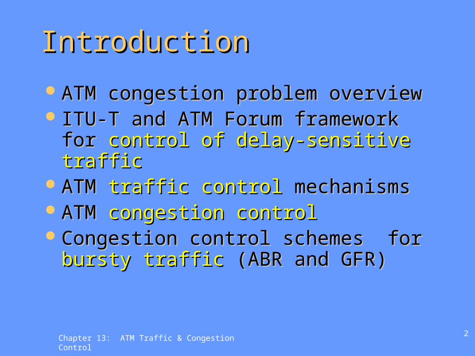
ATM Service CategoriesATM Service Categories Constant Bit Rate (CBR)Constant Bit Rate (CBR)
– fixed data rate required at guaranteed fixed data rate required at guaranteed capacitycapacity
Real-Time Variable Bit-Rate (rt-VBR)Real-Time Variable Bit-Rate (rt-VBR)– tightly constrained delay and delay variationtightly constrained delay and delay variation– sustained rate & guaranteed fast burst ratesustained rate & guaranteed fast burst rate
Non-Real-Time Variable Bit-Rate (nrt-VBR)Non-Real-Time Variable Bit-Rate (nrt-VBR)– no delay variation bound, cell loss ratio onlyno delay variation bound, cell loss ratio only
Available Bit Rate (ABR)Available Bit Rate (ABR)– guaranteed minimum capacity, with burstsguaranteed minimum capacity, with bursts
Guaranteed Frame Rate (GFR)Guaranteed Frame Rate (GFR)– like UBR/ABR, expressed in terms of frame ratelike UBR/ABR, expressed in terms of frame rate
Unspecified Bit Rate (UBR)Unspecified Bit Rate (UBR)– best-effort servicebest-effort service
Chapter 13: ATM Traffic & Congestion Control4
Why Typical Traffic Control Why Typical Traffic Control Schemes Are Inadequate for Schemes Are Inadequate for ATMATM Majority of ATM traffic Majority of ATM traffic sourcessources are time- are time-
sensitive, and not amenable to typical flow sensitive, and not amenable to typical flow control schemes (e.g. CBR, rt-VBR)control schemes (e.g. CBR, rt-VBR)
For long-haul ATM: tFor long-haul ATM: ttranstrans << t << tprop prop … … slow slow feedback (latency/speed effects)feedback (latency/speed effects)
Due to the broad range of ATM application Due to the broad range of ATM application types, flow control may types, flow control may indiscriminately indiscriminately penalizepenalize some some – bandwidth requirements (kbps to Mbps)bandwidth requirements (kbps to Mbps)– traffic patterns (CBR, VBR)traffic patterns (CBR, VBR)– service requirements (delay/loss sensitivity)service requirements (delay/loss sensitivity)
Very high-speed switching increases Very high-speed switching increases volatilityvolatility re: control mechanisms re: control mechanisms
Chapter 13: ATM Traffic & Congestion Control5
ATM Performance ATM Performance considerationsconsiderationsTwo key issues must be addressed Two key issues must be addressed
for CBR and real-time VBR traffic…for CBR and real-time VBR traffic…– Latency/speed effects for long-haul Latency/speed effects for long-haul
networks: networks: Cause - tCause - ttranstrans << 2 x t << 2 x tpropprop (or, one RTT) (or, one RTT)Approach – fast feedback mechanismsApproach – fast feedback mechanisms
– Cell delay variation:Cell delay variation:Cause - Variation at user-network interface Cause - Variation at user-network interface
and in network coreand in network coreApproach: time reassembly of CBR cells at Approach: time reassembly of CBR cells at
receiverreceiver
Chapter 13: ATM Traffic & Congestion Control6
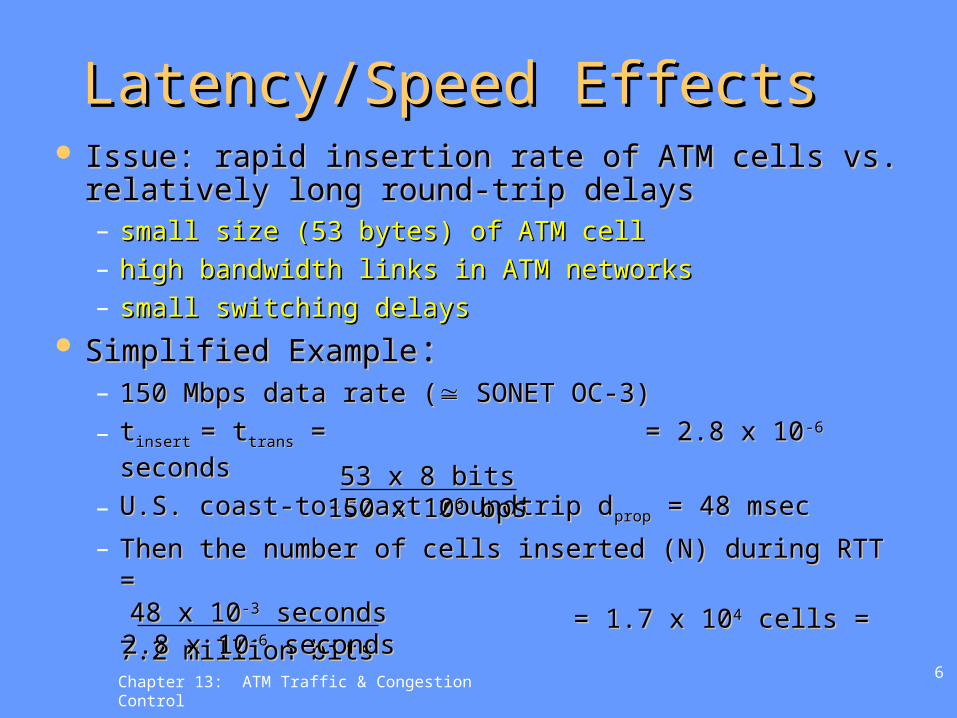
Latency/Speed EffectsLatency/Speed Effects Issue: rapid insertion rate of ATM cells vs. Issue: rapid insertion rate of ATM cells vs.
relatively long round-trip delaysrelatively long round-trip delays– small size (53 bytes) of ATM cellsmall size (53 bytes) of ATM cell– high bandwidth links in ATM networks high bandwidth links in ATM networks – small switching delays small switching delays
Simplified ExampleSimplified Example::– 150 Mbps data rate (150 Mbps data rate ( SONET OC-3) SONET OC-3)
– ttinsert insert = t= ttranstrans = = 2.8 x 10 = = 2.8 x 10⁻⁶-6 seconds seconds
– U.S. coast-to-coast roundtrip dU.S. coast-to-coast roundtrip dpropprop = 48 msec = 48 msec
– Then the number of cells inserted (N) during RTT =Then the number of cells inserted (N) during RTT =
= 1.7 x 10= 1.7 x 1044 cells = 7.2 million bits cells = 7.2 million bits
53 x 8 bits53 x 8 bits150 x 10150 x 1066 bps bps
48 x 1048 x 10-3-3 seconds seconds2.8 x 102.8 x 10-6-6 seconds seconds
Chapter 13: ATM Traffic & Congestion Control7
Cell Delay VariationCell Delay Variation General requirement: delay should General requirement: delay should
be shortbe short– ATM designed to ATM designed to minimize delayminimize delay
For some applications, For some applications, rate of rate of deliverydelivery of cells to destination must of cells to destination must be constant (ATM’s CBR service be constant (ATM’s CBR service level)level)
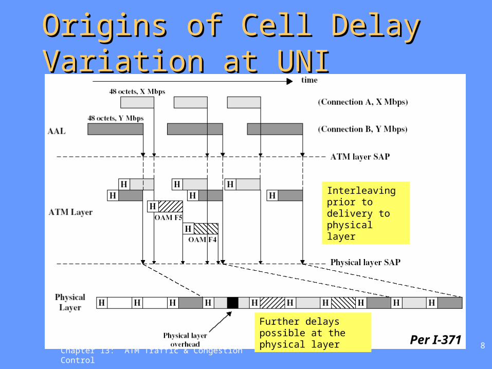
Contributors to cell delay variationContributors to cell delay variation– network contribution: network contribution: queuingqueuing and and
processing variationsprocessing variations– variation at variation at UNIUNI (user network (user network
interface) due to interface) due to cell processingcell processing
Chapter 13: ATM Traffic & Congestion Control8
Origins of Cell Delay Origins of Cell Delay Variation at UNIVariation at UNI
Per I-371
Interleaving prior to delivery to physical layer
Further delays possible at the physical layer
Chapter 13: ATM Traffic & Congestion Control9
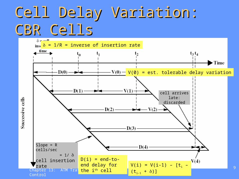
Cell Delay Variation: CBR Cell Delay Variation: CBR CellsCells
= 1/R = inverse of insertion rate
D(i) = end-to-end delay for the ith cell
V(i) = V(i-1) – [ti – (ti-1 + )]
cell arrives late: discarded
Slope = R cells/sec = 1/ cell insertion rate
V(0) = est. tolerable delay variation
Chapter 13: ATM Traffic & Congestion Control10
ATM AttributesATM Attributes
How we describe an ATM traffic flowHow we describe an ATM traffic flowTraffic parametersTraffic parametersQoS parametersQoS parametersCongestion (for ABR)Congestion (for ABR)Other (for UBR)Other (for UBR)
Chapter 13: ATM Traffic & Congestion Control11
Traffic ParametersTraffic ParametersConnection Traffic DescriptorConnection Traffic Descriptor
– Source Traffic DescriptorSource Traffic Descriptor: PCR, SCR, : PCR, SCR, MBS, MCR, MFS (more on next slide)MBS, MCR, MFS (more on next slide)
– Cell Delay Variation Tolerance (Cell Delay Variation Tolerance ()): upper : upper bound on amount of cell delay that is bound on amount of cell delay that is introduced by the network interface and introduced by the network interface and the UNI (due to interleaving, physical the UNI (due to interleaving, physical layer overhead, multiplexing, etc.) layer overhead, multiplexing, etc.)
Note- this is the value V(0) from our earlier Note- this is the value V(0) from our earlier discussion of CDVdiscussion of CDV
– Conformance DefinitionConformance Definition: unambiguous : unambiguous specification of conforming cells of a specification of conforming cells of a connection at the UNI (see connection at the UNI (see GCRAGCRA, later), later)
Chapter 13: ATM Traffic & Congestion Control12
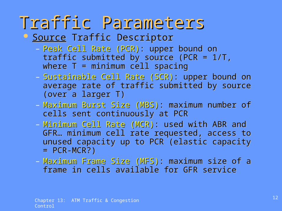
Traffic ParametersTraffic Parameters SourceSource Traffic Descriptor Traffic Descriptor
– Peak Cell Rate (PCR)Peak Cell Rate (PCR): upper bound on traffic : upper bound on traffic submitted by source (PCR = 1/T, where T = submitted by source (PCR = 1/T, where T = minimum cell spacingminimum cell spacing
– Sustainable Cell Rate (SCR)Sustainable Cell Rate (SCR): upper bound on : upper bound on average rate of traffic submitted by source average rate of traffic submitted by source (over a larger T)(over a larger T)
– Maximum Burst Size (MBS)Maximum Burst Size (MBS): maximum number : maximum number of cells sent continuously at PCRof cells sent continuously at PCR
– Minimum Cell Rate (MCR)Minimum Cell Rate (MCR): used with ABR and : used with ABR and GFR… minimum cell rate requested, access to GFR… minimum cell rate requested, access to unused capacity up to PCR (elastic capacity = unused capacity up to PCR (elastic capacity = PCR-MCR?)PCR-MCR?)
– Maximum Frame Size (MFS)Maximum Frame Size (MFS): maximum size of : maximum size of a frame in cells available for GFR servicea frame in cells available for GFR service
Chapter 13: ATM Traffic & Congestion Control13
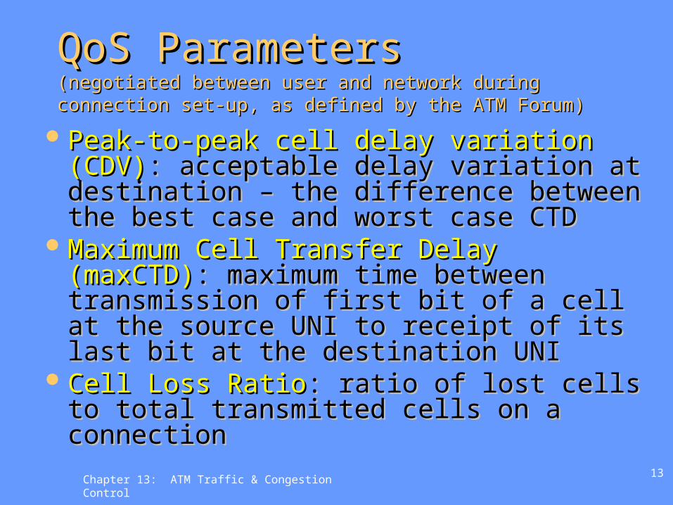
QoS Parameters QoS Parameters (negotiated between user and network during connection (negotiated between user and network during connection set-up, as defined by the ATM Forum)set-up, as defined by the ATM Forum)
Peak-to-peak cell delay variation Peak-to-peak cell delay variation (CDV)(CDV): acceptable delay variation at : acceptable delay variation at destination – the difference between destination – the difference between the best case and worst case CTDthe best case and worst case CTD
Maximum Cell Transfer Delay Maximum Cell Transfer Delay (maxCTD)(maxCTD): maximum time between : maximum time between transmission of first bit of a cell at the transmission of first bit of a cell at the source UNI to receipt of its last bit at source UNI to receipt of its last bit at the destination UNIthe destination UNI
Cell Loss RatioCell Loss Ratio: ratio of lost cells to : ratio of lost cells to total transmitted cells on a connectiontotal transmitted cells on a connection
Chapter 13: ATM Traffic & Congestion Control14
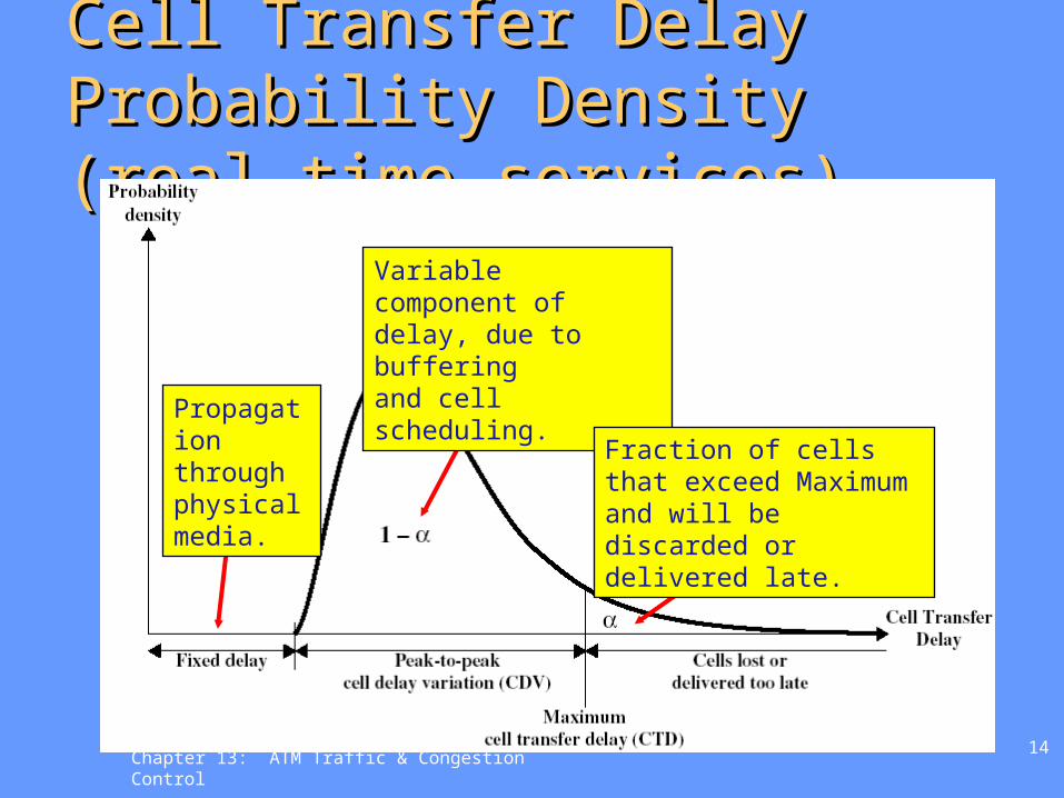
Cell Transfer Delay Cell Transfer Delay Probability Density (real-time Probability Density (real-time services)services)
Variable component of delay, due to buffering and cell scheduling.
Fraction of cells that exceed Maximum and will be discarded or delivered late.
Propagation throughphysical media.
Chapter 13: ATM Traffic & Congestion Control15
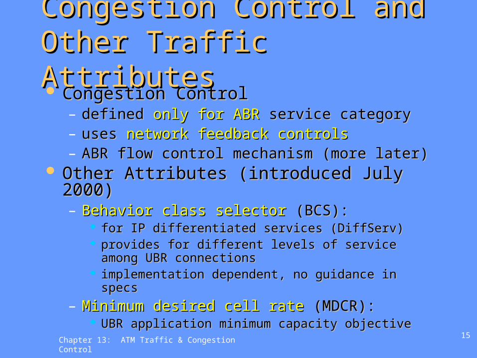
Congestion Control and Congestion Control and Other Traffic AttributesOther Traffic Attributes Congestion ControlCongestion Control
– defined defined only for ABRonly for ABR service categoryservice category– uses uses network feedback controlsnetwork feedback controls– ABR flow control mechanism (more later)ABR flow control mechanism (more later)
Other Attributes (introduced July 2000)Other Attributes (introduced July 2000)– Behavior class selectorBehavior class selector (BCS): (BCS):
for IP differentiated services (DiffServ)for IP differentiated services (DiffServ) provides for different levels of service among provides for different levels of service among
UBR connectionsUBR connections implementation dependent, no guidance in implementation dependent, no guidance in
specsspecs
– Minimum desired cell rateMinimum desired cell rate (MDCR): (MDCR): UBR application minimum capacity objectiveUBR application minimum capacity objective
Chapter 13: ATM Traffic & Congestion Control16
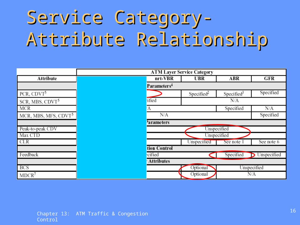
Service Category-Attribute Service Category-Attribute RelationshipRelationship
Chapter 13: ATM Traffic & Congestion Control17
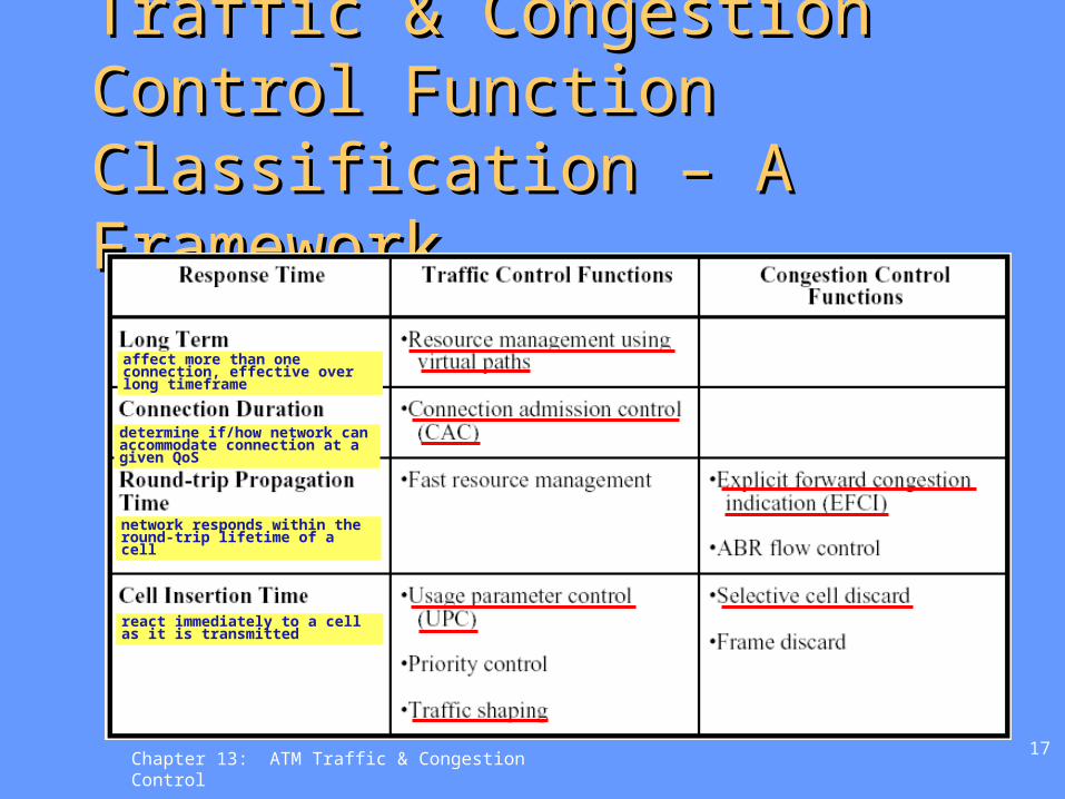
Traffic & Congestion Traffic & Congestion Control Function Control Function Classification – A Classification – A FrameworkFramework
affect more than one connection, effective over long timeframe
determine if/how network can accommodate connection at a given QoS
network responds within the round-trip lifetime of a cell
react immediately to a cell as it is transmitted
Chapter 13: ATM Traffic & Congestion Control18
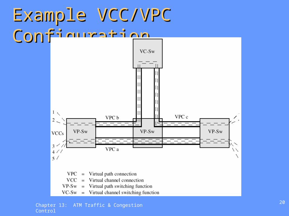
Resource Management Resource Management Using Virtual PathsUsing Virtual Paths Multiple VCCs with various QoS Multiple VCCs with various QoS
requirements in same VPC requirements in same VPC Cases to consider:Cases to consider:
– User-to-User applicationUser-to-User application:: VPCs between pairs of VPCs between pairs of UNIs, VCC QoS is user’s responsibility… user UNIs, VCC QoS is user’s responsibility… user must ensure that aggregate of VCCs does not must ensure that aggregate of VCCs does not exceed capacity allocated to VPCexceed capacity allocated to VPC
– User-to-network applicationUser-to-network application:: VPC between UNI VPC between UNI and network node, network must accommodate and network node, network must accommodate QoS of individual VCCsQoS of individual VCCs
– Network-to-network applicationNetwork-to-network application:: network must network must accommodate QoS of individual VCCsaccommodate QoS of individual VCCs
Chapter 13: ATM Traffic & Congestion Control19
Resource Management Resource Management Using Virtual PathsUsing Virtual Paths Performance (QoS) of a VCC depends on Performance (QoS) of a VCC depends on
resources allocated to the VPC(s) through resources allocated to the VPC(s) through which the VCC extendswhich the VCC extends
Network allocates capacity to each VPCNetwork allocates capacity to each VPC based on performance objectives agreed based on performance objectives agreed between network and subscriber between network and subscriber (contract). Two approaches:(contract). Two approaches:– Aggregate peak demandAggregate peak demand – VPC capacity (e.g. – VPC capacity (e.g.
data rate) set to sum of peak data rates of all data rate) set to sum of peak data rates of all VCCsVCCs
– Statistical multiplexingStatistical multiplexing – VPC capacity set to be – VPC capacity set to be greater than or equal to average demand for all greater than or equal to average demand for all VCCs, but less than aggregate peak demandVCCs, but less than aggregate peak demand
Chapter 13: ATM Traffic & Congestion Control20
Example VCC/VPC Example VCC/VPC ConfigurationConfiguration
Chapter 13: ATM Traffic & Congestion Control21
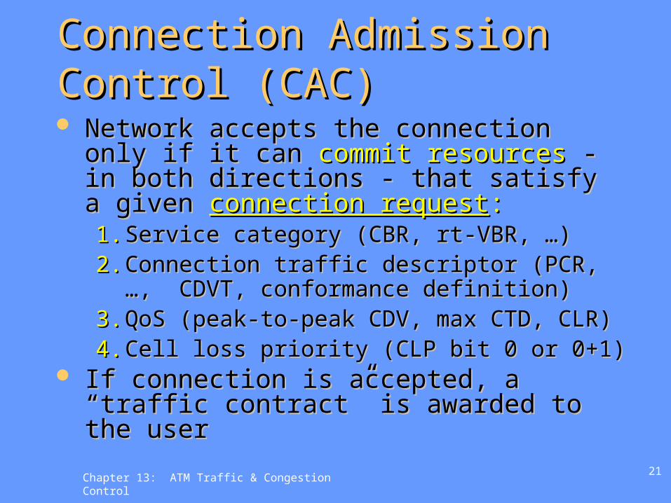
Connection Admission Connection Admission Control (CAC)Control (CAC) Network accepts the connection only Network accepts the connection only
if it can if it can commit resourcescommit resources - in both - in both directions - that satisfy a given directions - that satisfy a given connection requestconnection request::1.1. Service category (CBR, rt-VBR, …)Service category (CBR, rt-VBR, …)2.2. Connection traffic descriptor (PCR, …, Connection traffic descriptor (PCR, …,
CDVT, conformance definition)CDVT, conformance definition)3.3. QoS (peak-to-peak CDV, max CTD, QoS (peak-to-peak CDV, max CTD,
CLR)CLR)4.4. Cell loss priority (CLP bit 0 or 0+1)Cell loss priority (CLP bit 0 or 0+1)
If connection is accepted, a “traffic If connection is accepted, a “traffic contract” is awarded to the usercontract” is awarded to the user
Chapter 13: ATM Traffic & Congestion Control22
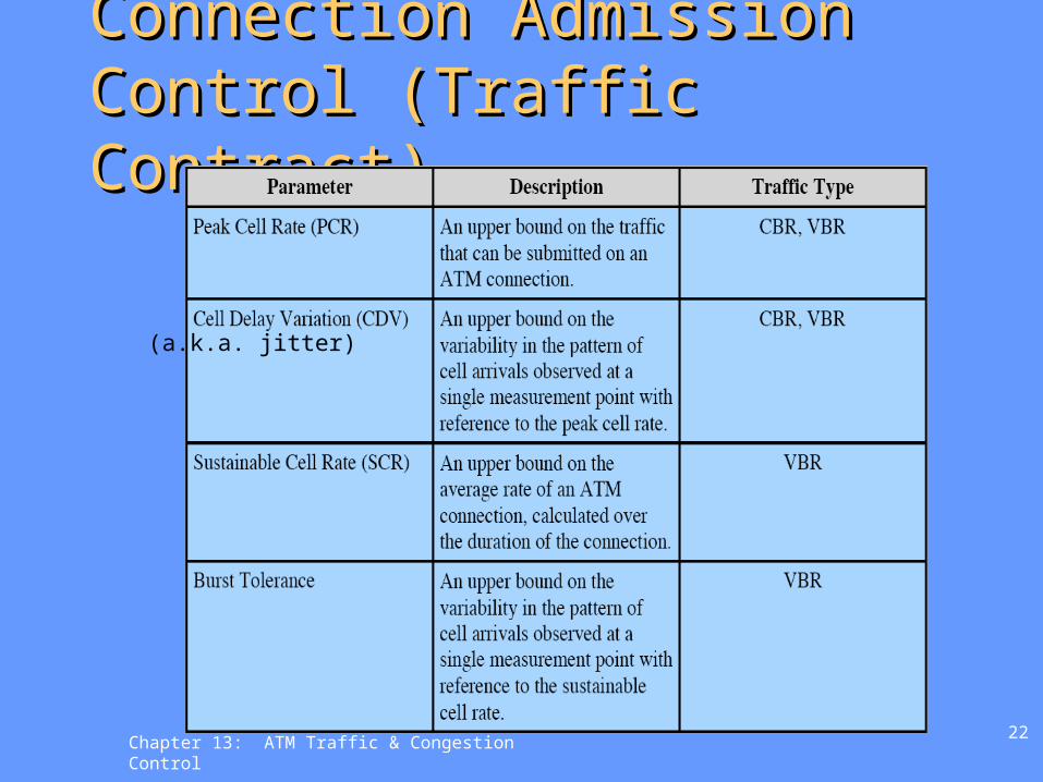
Connection Admission Connection Admission Control (Traffic Contract)Control (Traffic Contract)
(a.k.a. jitter)
Chapter 13: ATM Traffic & Congestion Control23
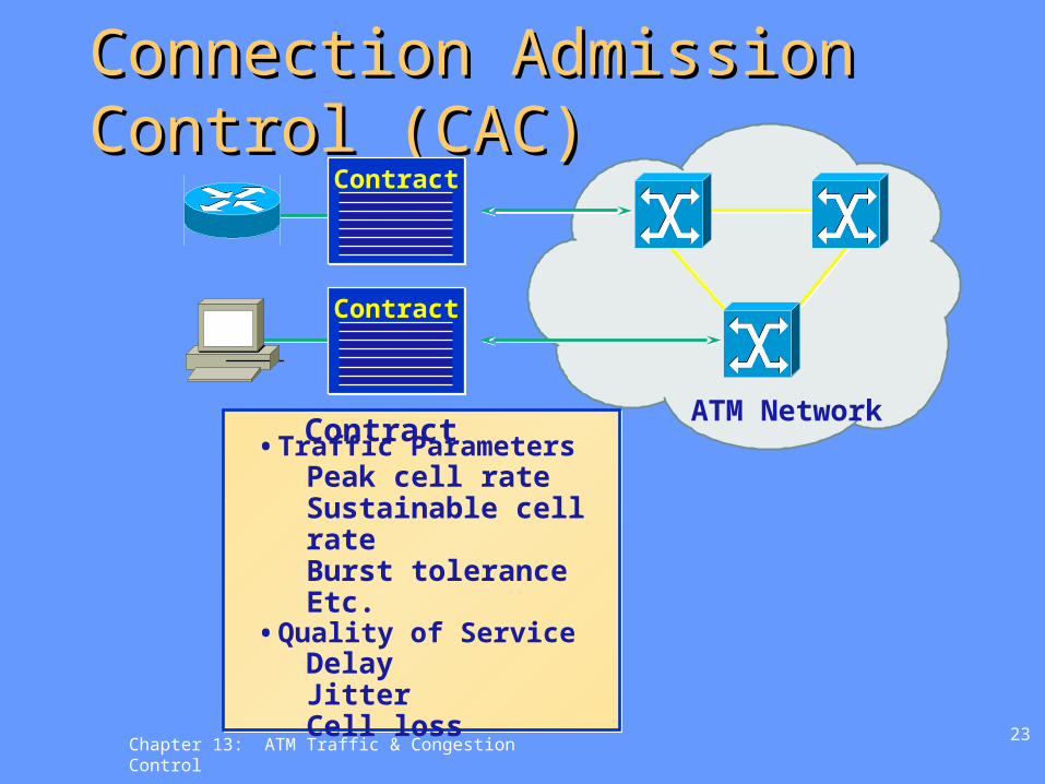
Connection Admission Connection Admission Control (CAC)Control (CAC)
Contract
Contract
Contract
• Traffic ParametersPeak cell rateSustainable cell rateBurst toleranceEtc.
• Quality of ServiceDelay JitterCell loss
ATM Network
Chapter 13: ATM Traffic & Congestion Control25
Usage Parameter ControlUsage Parameter Control
Purpose: after a connection is Purpose: after a connection is established, established, protect the network’sprotect the network’s resources resources from overload/abusefrom overload/abuse by by violating connectionsviolating connections
Monitors connection for Monitors connection for conformanceconformance to the traffic contract to the traffic contract– detect violation of assigned detect violation of assigned
parameters based on conformance parameters based on conformance definition agreed to in contractdefinition agreed to in contract
– take appropriate actiontake appropriate action
Chapter 13: ATM Traffic & Congestion Control26
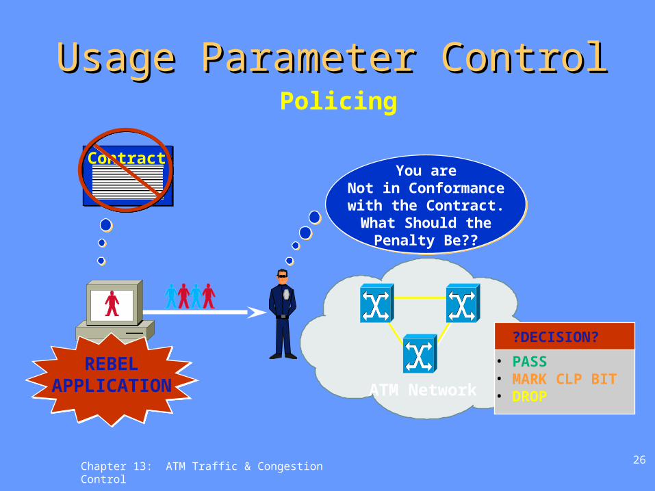
Usage Parameter ControlUsage Parameter Control
ATM Network
You areNot in Conformance
with the Contract.What Should the
Penalty Be??
• PASS• MARK CLP BIT• DROP
?DECISION?
Policing
REBELAPPLICATION
Contract
Chapter 13: ATM Traffic & Congestion Control27
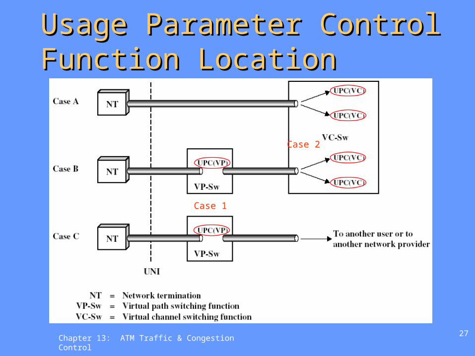
Usage Parameter Control Usage Parameter Control Function LocationFunction Location
Case 2
Case 1
Chapter 13: ATM Traffic & Congestion Control28
UPC Traffic ManagementUPC Traffic ManagementPeak Cell Rate AlgorithmPeak Cell Rate Algorithm
– Regulates the peak cell rateRegulates the peak cell rate and the and the associated CDVT of a connectionassociated CDVT of a connection
Sustainable Cell Rate AlgorithmSustainable Cell Rate Algorithm– Regulates the sustainable cell rateRegulates the sustainable cell rate
and associated and associated burst toleranceburst tolerance of a of a connectionconnection
Traffic ShapingTraffic Shaping– SmoothesSmoothes out traffic at network out traffic at network
entry points to reduce “clumping”entry points to reduce “clumping”– Reduce delays, ensure Reduce delays, ensure fair resource fair resource
allocationallocation
Chapter 13: ATM Traffic & Congestion Control29
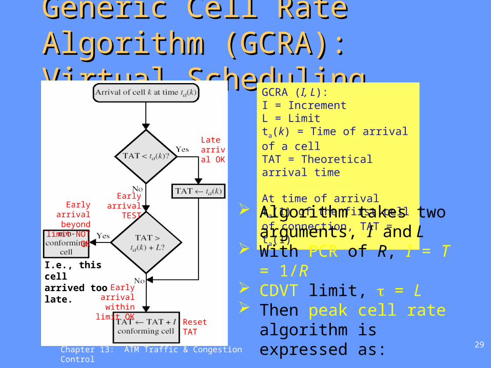
Generic Cell Rate Algorithm Generic Cell Rate Algorithm (GCRA): Virtual Scheduling(GCRA): Virtual Scheduling
GCRA (I, L):I = IncrementL = Limitta(k) = Time of arrival of a cellTAT = Theoretical arrival time
At time of arrival ta(1) of the first cell of connection, TAT = ta(1)
Algorithm takes two arguments, I and L
With PCR of R, I = T = 1/R
CDVT limit, = L Then peak cell rate
algorithm is expressed as:
GCRA(T, )
I.e., this cell arrived too late.
Late arrival OK
Reset TAT
Early arrival within limit
OK
Early arrival beyond limit
NOT OK
Early arrival TEST
Chapter 13: ATM Traffic & Congestion Control33
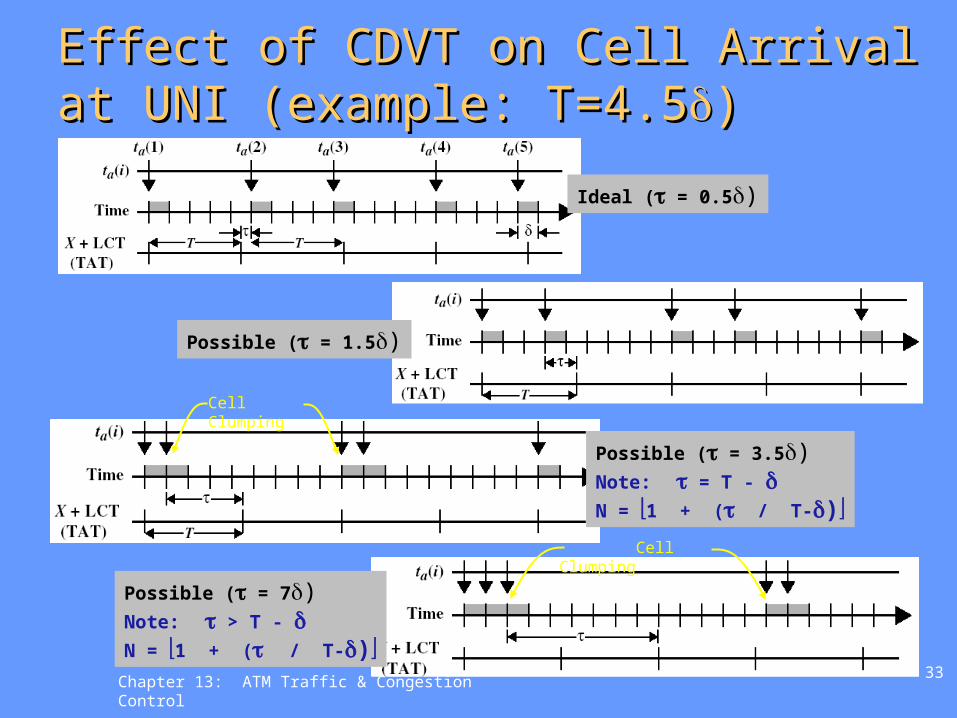
Effect of CDVT on Cell Arrival at UNI Effect of CDVT on Cell Arrival at UNI (example: T=4.5(example: T=4.5))
Ideal ( = 0.5)
Possible ( = 1.5)
Possible ( = 3.5)Note: = T - N = 1 + ( / T-)
Possible ( = 7)Note: > T - N = 1 + ( / T-)
Cell Clumping
Cell Clumping
Chapter 13: ATM Traffic & Congestion Control34
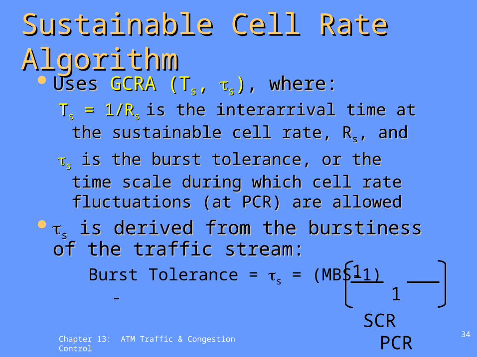
Sustainable Cell Rate Sustainable Cell Rate AlgorithmAlgorithm
Uses Uses GCRA (TGCRA (Tss, , ss)), where:, where:TTss = 1/R = 1/Rss is the interarrival time at the is the interarrival time at the
sustainable cell rate, Rsustainable cell rate, Rss, and, and
ss is the burst tolerance, or the time is the burst tolerance, or the time scale during which cell rate scale during which cell rate fluctuations (at PCR) are allowedfluctuations (at PCR) are allowed
ss is derived from the burstiness of is derived from the burstiness of the traffic stream:the traffic stream: Burst Tolerance = s = (MBS-1)
-
1 1SCR PCR
Chapter 13: ATM Traffic & Congestion Control35
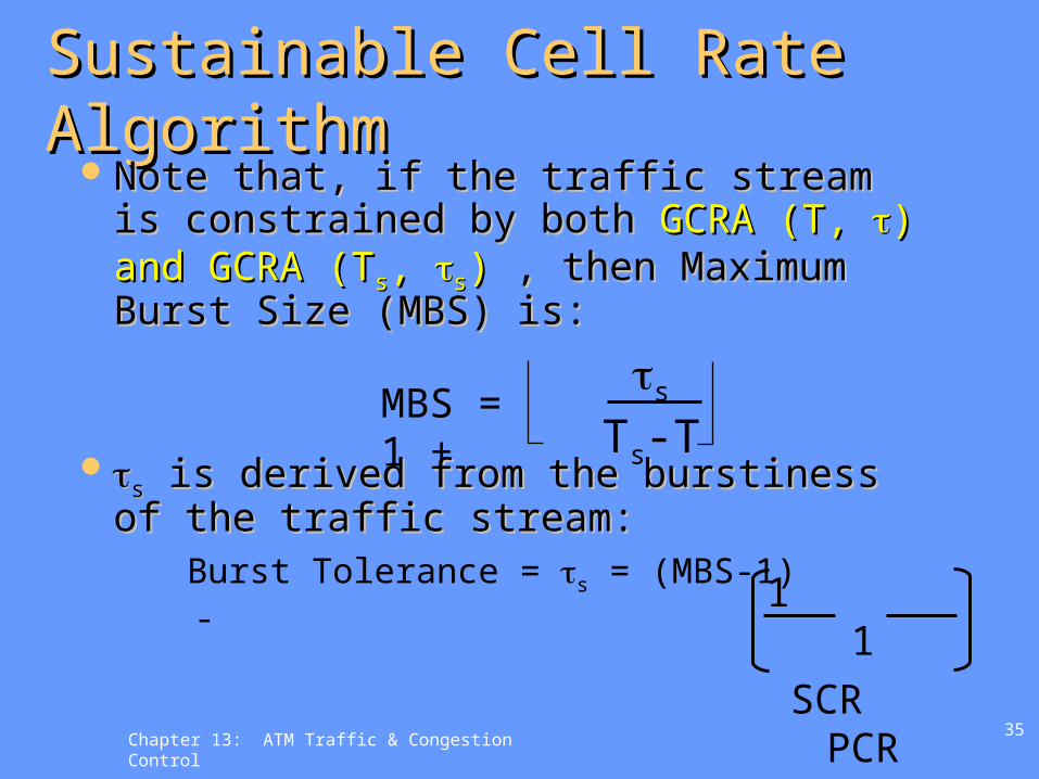
Sustainable Cell Rate Sustainable Cell Rate AlgorithmAlgorithm
Note that, if the traffic stream is Note that, if the traffic stream is constrained by both constrained by both GCRA (T, GCRA (T, ) ) and GCRA (Tand GCRA (Tss, , ss) ) , then Maximum , then Maximum Burst Size (MBS) is:Burst Size (MBS) is:
ss is derived from the burstiness of is derived from the burstiness of the traffic stream:the traffic stream: Burst Tolerance = s = (MBS-1)
-
1 1SCR PCR
MBS = 1 +
s
Ts-T
Chapter 13: ATM Traffic & Congestion Control36
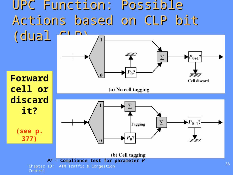
UPC Function: Possible Actions UPC Function: Possible Actions based on CLP bit (dual CLP)based on CLP bit (dual CLP)
P? = Compliance test for parameter P
Forward cell or discard
it?
(see p. 377)
Chapter 13: ATM Traffic & Congestion Control37
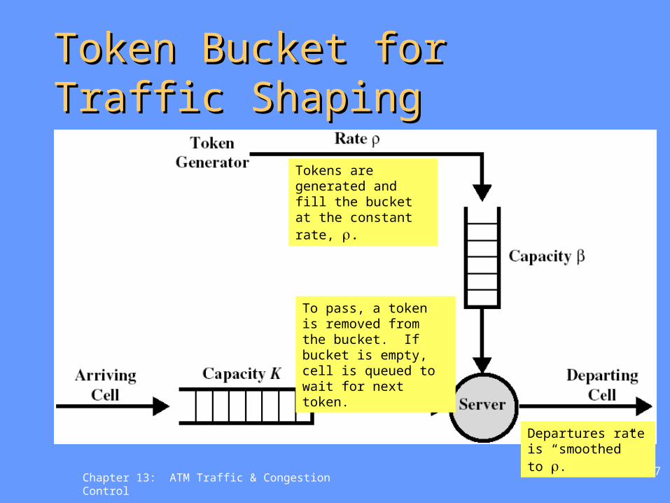
Token Bucket for Traffic Token Bucket for Traffic ShapingShaping
Tokens are generated and fill the bucket at the constant rate, .
To pass, a token is removed from the bucket. If bucket is empty, cell is queued to wait for next token.
Departures rate is “smoothed” to .
Chapter 13: ATM Traffic & Congestion Control38
ABR Traffic ManagementABR Traffic ManagementCBR, rt-VBR, nrt-VBR: traffic contract CBR, rt-VBR, nrt-VBR: traffic contract
with with open-loop controlopen-loop controlUBR: best effort sharing of unused UBR: best effort sharing of unused
capacitycapacityABR: share unused (available) ABR: share unused (available)
capacity using capacity using closed-loop controlclosed-loop control of of sourcesource– Allowed Cell Rate (ACR):Allowed Cell Rate (ACR): current max. cell current max. cell
transmission ratetransmission rate– Minimum Cell Rate (MCR)Minimum Cell Rate (MCR): network : network
guaranteed minimum cell rateguaranteed minimum cell rate– Peak Cell Rate (PCR):Peak Cell Rate (PCR): max. value for ACR max. value for ACR– Initial Cell Rate (ICR):Initial Cell Rate (ICR): initial value of ACR initial value of ACR
Chapter 13: ATM Traffic & Congestion Control39
ABR Traffic ManagementABR Traffic Management
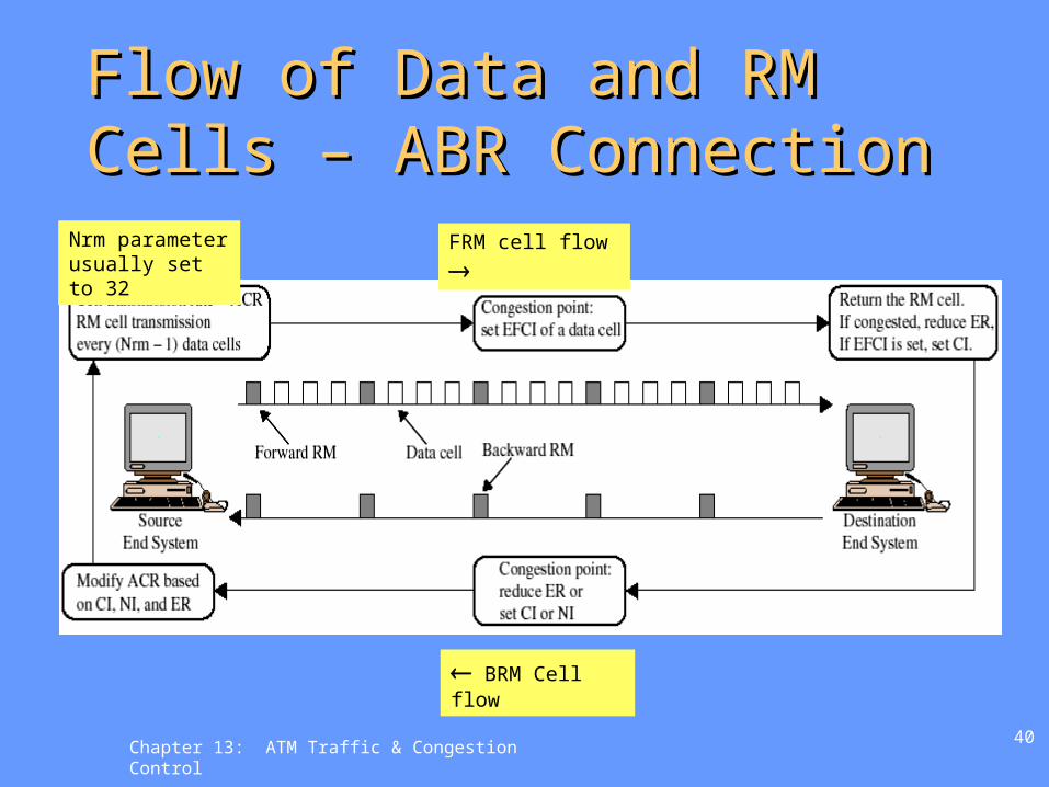
ACR is dynamically adjustedACR is dynamically adjusted based on feedback to the source based on feedback to the source in the form of in the form of Resource Resource Management (RM) cellsManagement (RM) cells
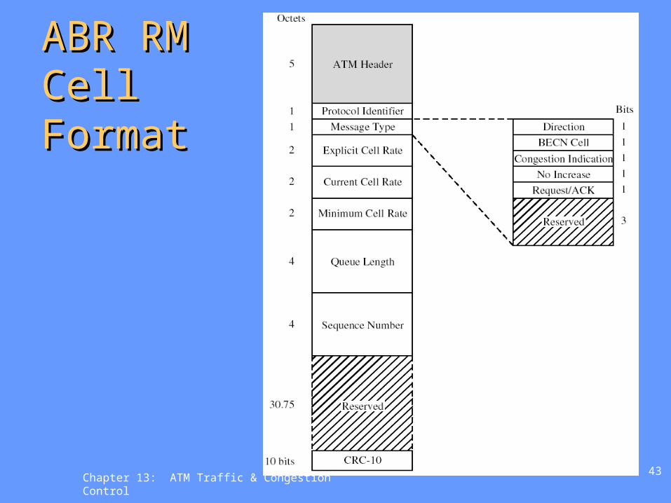
RM cells contain three fields:RM cells contain three fields:– Congestion Indication (CI) bitCongestion Indication (CI) bit– No Increase (NI) bitNo Increase (NI) bit– Explicit Cell Rate (ER) fieldExplicit Cell Rate (ER) field
Chapter 13: ATM Traffic & Congestion Control40
Flow of Data and RM Cells – Flow of Data and RM Cells – ABR ConnectionABR Connection
Nrm parameter usually set to 32
FRM cell flow
BRM Cell flow
Chapter 13: ATM Traffic & Congestion Control41
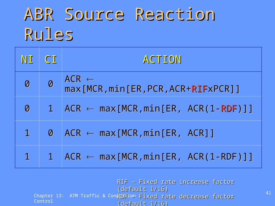
ABR Source Reaction RulesABR Source Reaction Rules
NINI CICI ACTIONACTION
00 00 ACR ACR max[MCR,min[ER,PCR,ACR+max[MCR,min[ER,PCR,ACR+RIFRIFxPCR]]xPCR]]
00 11 ACR ACR max[MCR,min[ER, ACR(1- max[MCR,min[ER, ACR(1-RDFRDF)]])]]
11 00 ACR ACR max[MCR,min[ER, ACR]] max[MCR,min[ER, ACR]]
11 11 ACR ACR max[MCR,min[ER, ACR(1-RDF)]] max[MCR,min[ER, ACR(1-RDF)]]
RIF – Fixed rate increase factor (default 1/16)RIF – Fixed rate increase factor (default 1/16)RDF – Fixed rate decrease factor (default RDF – Fixed rate decrease factor (default 1/16)1/16)
Chapter 13: ATM Traffic & Congestion Control42
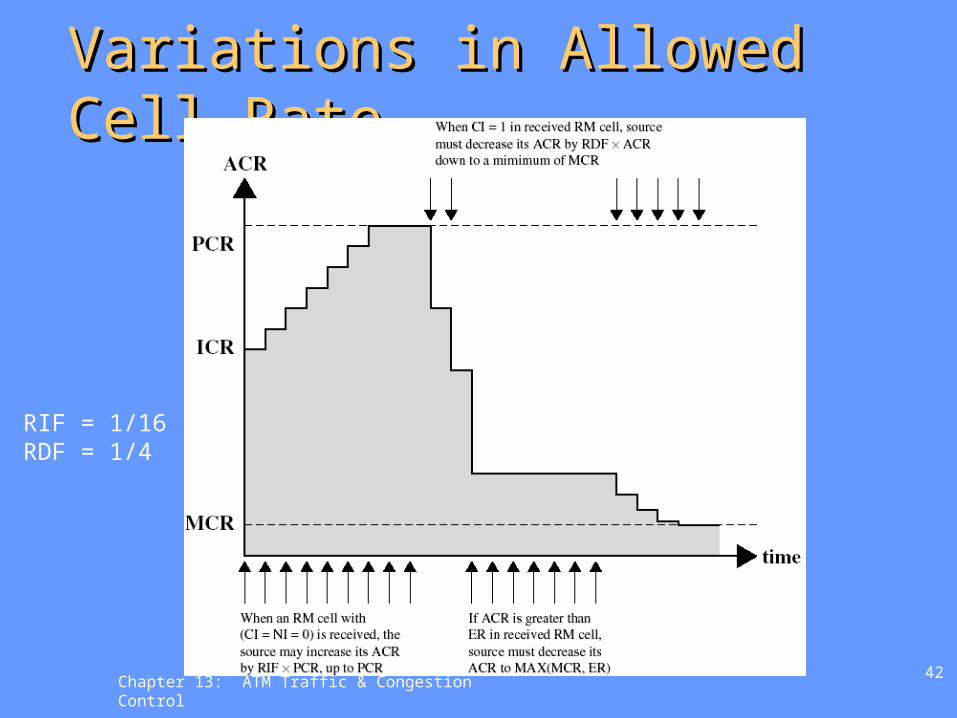
Variations in Allowed Cell Variations in Allowed Cell RateRate
RIF = 1/16RDF = 1/4
Chapter 13: ATM Traffic & Congestion Control43
ABR RM ABR RM Cell Cell FormatFormat
Chapter 13: ATM Traffic & Congestion Control44
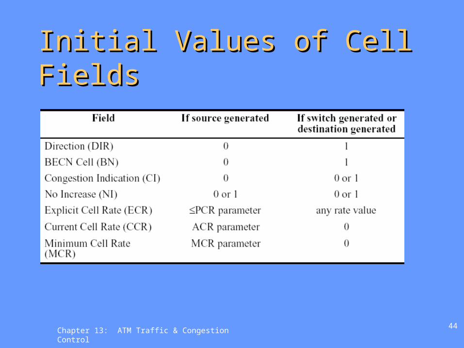
Initial Values of Cell FieldsInitial Values of Cell Fields
Chapter 13: ATM Traffic & Congestion Control45
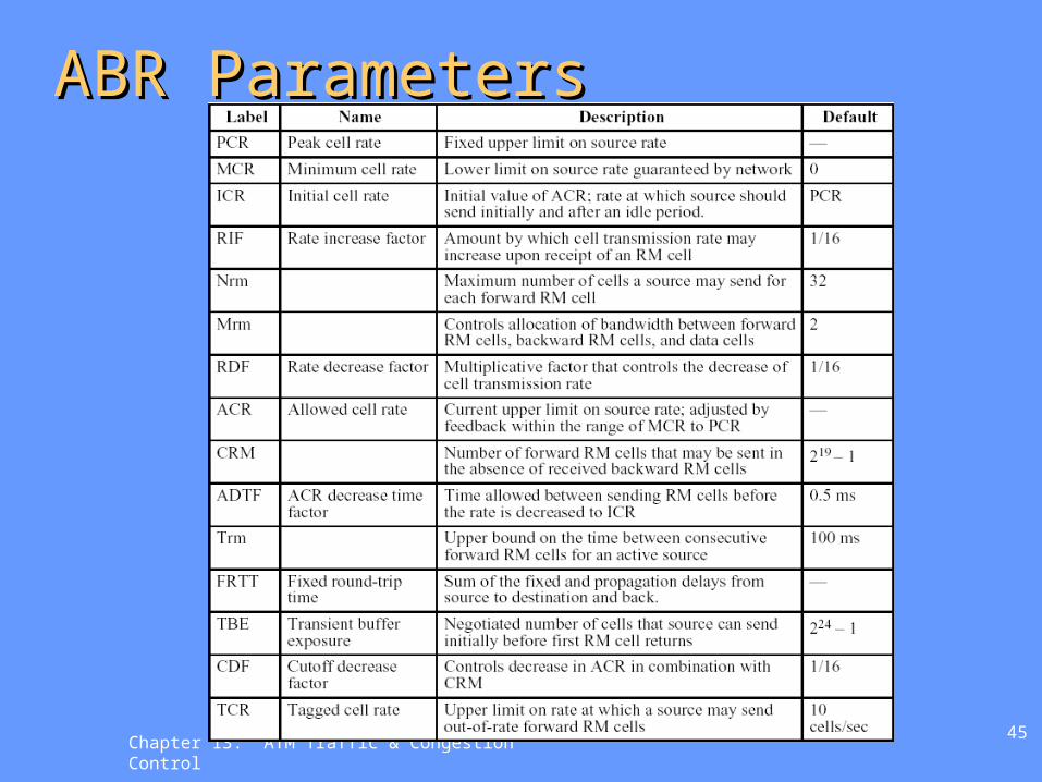
ABR ParametersABR Parameters
Chapter 13: ATM Traffic & Congestion Control46
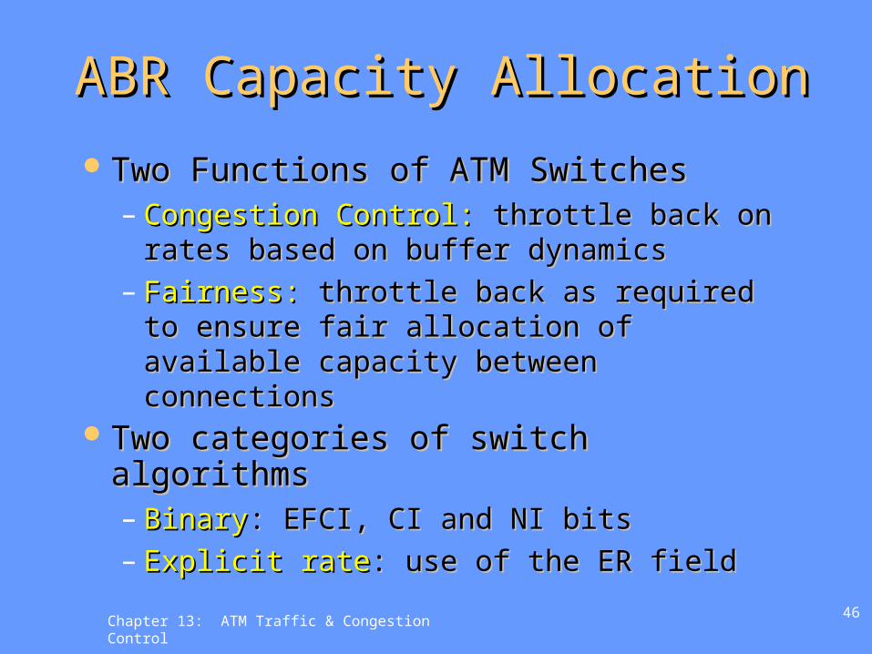
ABR Capacity AllocationABR Capacity Allocation
Two Functions of ATM SwitchesTwo Functions of ATM Switches– Congestion Control:Congestion Control: throttle back on throttle back on
rates based on buffer dynamicsrates based on buffer dynamics– Fairness:Fairness: throttle back as required to throttle back as required to
ensure fair allocation of available ensure fair allocation of available capacity between connectionscapacity between connections
Two categories of switch Two categories of switch algorithmsalgorithms– BinaryBinary: EFCI, CI and NI bits: EFCI, CI and NI bits– Explicit rateExplicit rate: use of the ER field: use of the ER field
Chapter 13: ATM Traffic & Congestion Control47
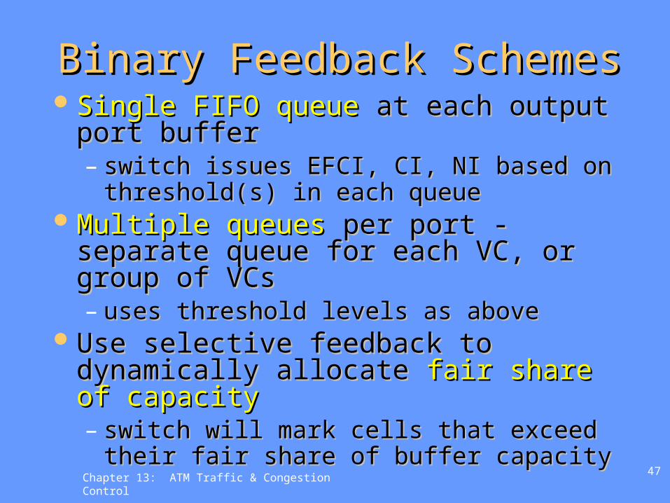
Binary Feedback SchemesBinary Feedback SchemesSingle FIFO queueSingle FIFO queue at each output at each output
port bufferport buffer– switch issues EFCI, CI, NI based on switch issues EFCI, CI, NI based on
threshold(s) in each queuethreshold(s) in each queueMultiple queuesMultiple queues per port - separate per port - separate
queue for each VC, or group of VCsqueue for each VC, or group of VCs– uses threshold levels as aboveuses threshold levels as above
Use selective feedback to Use selective feedback to dynamically allocate dynamically allocate fair share of fair share of capacitycapacity– switch will mark cells that exceed switch will mark cells that exceed
their fair share of buffer capacitytheir fair share of buffer capacity
Chapter 13: ATM Traffic & Congestion Control48
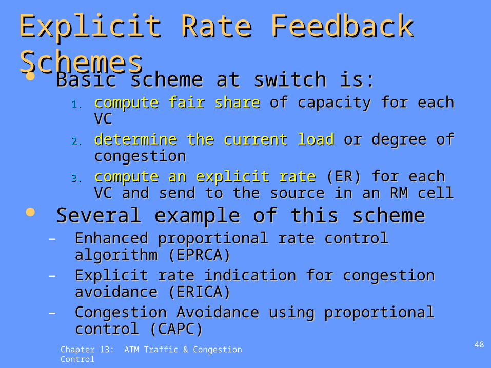
Explicit Rate Feedback Explicit Rate Feedback SchemesSchemes Basic scheme at switch is:Basic scheme at switch is:
1.1. compute fair sharecompute fair share of capacity for each VC of capacity for each VC2.2. determine the current loaddetermine the current load or degree of or degree of
congestioncongestion3.3. compute an explicit ratecompute an explicit rate (ER) for each VC (ER) for each VC
and send to the source in an RM celland send to the source in an RM cell Several example of this schemeSeveral example of this scheme
– Enhanced proportional rate control algorithm Enhanced proportional rate control algorithm (EPRCA)(EPRCA)
– Explicit rate indication for congestion Explicit rate indication for congestion avoidance (ERICA)avoidance (ERICA)
– Congestion Avoidance using proportional Congestion Avoidance using proportional control (CAPC)control (CAPC)
Chapter 13: ATM Traffic & Congestion Control49
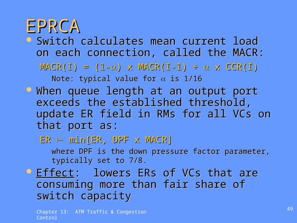
EPRCAEPRCA Switch calculates mean current load on Switch calculates mean current load on
each connection, called the MACR:each connection, called the MACR:MACR(I) = (1-MACR(I) = (1-) x MACR(I-1) + ) x MACR(I-1) + x CCR(I) x CCR(I)
Note: typical value for Note: typical value for is 1/16 is 1/16
When queue length at an output port When queue length at an output port exceeds the established threshold, exceeds the established threshold, update ER field in RMs for all VCs on that update ER field in RMs for all VCs on that port as:port as:ER ER min[ER, DPF x MACR] min[ER, DPF x MACR]
where DPF is the down pressure factor parameter, where DPF is the down pressure factor parameter, typically set to 7/8.typically set to 7/8.
EffectEffect: lowers ERs of VCs that are : lowers ERs of VCs that are consuming more than fair share of consuming more than fair share of switch capacityswitch capacity
Chapter 13: ATM Traffic & Congestion Control50
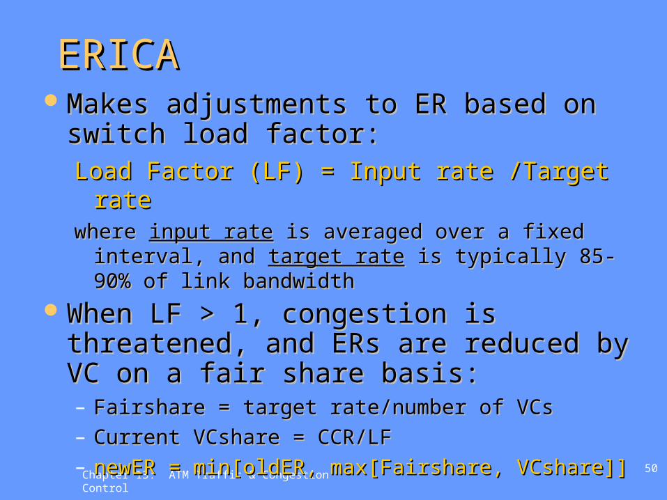
ERICAERICAMakes adjustments to ER based on Makes adjustments to ER based on
switch load factor:switch load factor:Load Factor (LF) = Input rate /Target rateLoad Factor (LF) = Input rate /Target ratewhere where input rateinput rate is averaged over a fixed is averaged over a fixed
interval, and interval, and target ratetarget rate is typically 85-90% of is typically 85-90% of link bandwidthlink bandwidth
When LF > 1, congestion is When LF > 1, congestion is threatened, and ERs are reduced by threatened, and ERs are reduced by VC on a fair share basis:VC on a fair share basis:– Fairshare = target rate/number of VCsFairshare = target rate/number of VCs– Current VCshare = CCR/LF Current VCshare = CCR/LF – newER = min[oldER, max[Fairshare, VCshare]]newER = min[oldER, max[Fairshare, VCshare]]