Embed Size (px)
Citation preview

RE 82 425/2000-02
STAR – Linear Modules LKLopen type
X4
12
34
56
12
39
10
11
4 12
5 13
6 14
7 15
8 16
X3
X1
X2
X30
Indramat
AC-CONTROLLER
DANGER!
High voltageDanger of electrical shock
Do not touch electrical connnections for
5 minutes after switching power off.
Read and follow Safety instructions for
Electrical Drives´ manual
DOK-GENERAL-DRIVE******* SVS
before operating
S2
S3
S1
8.8
X8
LS100-XXXX

RE 82 425/2000-022
STAR – Linear Motion Technology
Ball Rail Systems Standard Ball Rail Systems
Ball Rail Systems with Aluminum Runner Blocks
Super Ball Rail Systems
Wide Ball Rail Systems
Accessories
Miniature Ball Rail Systems
Cam Roller Guides
Roller Rail Systems
Linear Bushings and Shafts Linear Bushings
Linear Sets
Shafts
Shaft Support Rails
Shaft Support Blocks
Ball Transfer Units
Other Engineering Components
Screw Drives
Linear Motion Systems Linear Motion Slides • Ball Screw Drive• Toothed Belt Drive
Linear Modules • Linear Motor
• Toothed Belt Drive• Rack and Pinion Drive• Pneumatic Drive• Ball Screw Drive
Compact Modules • Ball Screw Drive
Precision Modules • Ball Screw Drive
Ball Rail Tables • Ball Screw Drive
• Linear Motor
ALU-STAR Profile System
Controllers, Motors, Electrical Accessories
Linear Actuators
RE 82 425/2000-02 3
Linear Modules LKL, open type
Product Overview 4The Drive Unit 6
The Control System 7
Type Designation with Load Capacities 8
Technical Data 10
Linear Module LKL 15-70, open type 16Components and Ordering Data 16
Dimension Drawings 18
Linear Module LKL 20-85, open type 20Components and Ordering Data 20
Dimension Drawings 22
Linear Encoder 24
Power Cable Chain 25
Switch Mounting 26
Mounting Instructions 28
Documentation 30

4 RE 82 425/2000-02
STAR – Linear Modules LKL
X4
12
34
56
12
39
10
11
4 12
5 13
6 14
7 15
8 16
X3
X1
X2
X30
Indramat
AC-CONTROLLER
DANGER!
High voltageDanger of electrical shock
Do not touch electrical connnections for
5 minutes after switching power off.
Read and follow Safety instructions for
Electrical Drives´ manual
DOK-GENERAL-DRIVE******* SVS
before operating
S2
S3
S1
8.8
X8
LS100-XXXX
Linear Modules LKL will help you to solve linear motion tasks rapidly andcost-effectively in a wide variety of different applications – from simplesingle-axis systems to complex multi-axis configurations for horizontaloperation.
The combination of synchronous linear motor, ball rail system and carriagesubstantially reduces the complexity of mechanical structures usuallyneeded for a linear motion axis.
The system is controlled via a standard servo controller DKC**.3.
This controller is available with analog, stepping motor, and positioninginterfaces, or with a Sercos interface or fieldbus interfaces.
As an option, linear modules LKL can be supplied with an incrementallinear encoder.
Product Overview
Cost savings throughshorter cycle times
Take the direct route tosuccess: our Linear Modulewith Linear Motor!
Application examples:(preferably for horizontal operation)
– Factory automation systems
– Medical and biomedical equipment
– Scanning and printing systems
– Electronics and the packaging industry
Not suitable for machining of ferrous materials.
Supplied as a complete “plug inand go” linear module withmatching servo amplifier
Mounting instructions:See RDEFI 82 473
, open type
Convenient Drive Topstart-up program
Control signals via a standardservo controller
Linear Modules LKL

5RE 82 425/2000-02
In preparation: Linear Module MKL 20-110
Linear Module LKL
Silent operation
Thrust generated directly atthe payload
LS100-XXXX
STSTARAR
STSTARAR
High positional accuracyand repeatability
Ball rail system unaffected by magneticforces
One-point lubrication forball rail system
High speed range,high dynamic response
Constant thrust evenat low speed
Rapid implementation
6 RE 82 425/2000-02
STAR – Linear Modules LKLProduct Overview
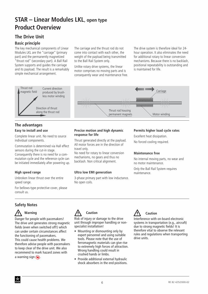
Basic principleThe key mechanical components of LinearModules LKL are the “carriage” (primarypart) and the permanently magnetized“thrust rod” (secondary part). A Ball RailSystem supports and guides the carriageand its payload. The result is a remarkablysimple mechanical arrangement.
The Drive Unit
Motor windingThrust rod housingpermanent magnets
CarriageThrust rodmagnetic field
Current directionproduced by brush-less motor winding
Direction of thrustalong the thrust rod
Easy to install and use
Complete linear unit. No need to sourceindividual components.
Commutation is determined via Hall effectsensors during the cut-in stage.Consequently there is no need for a com-mutation cycle and the reference cycle canbe initiated immediately after powering up.
The advantages
High speed range
Unbroken linear thrust over the entirespeed range.
For bellows-type protective cover, pleaseconsult us.
, open type
Permits higher load cycle rates
Excellent heat dissipation.
No forced cooling required.
Maintenance free
No internal moving parts, no wear andno motor maintenance.
Only the Ball Rail System requiresmaintenance.Ultra low EMI generation
3-phase primary part with low inductance.No open coils.
Precise motion and high dynamicresponse for life
Thrust generated directly at the payload.All motor forces are in the direction oftravel only.No need for rotary to linear conversionmechanisms, no gears and thus nobacklash. Non critical alignment.
The carriage and the thrust rod do notcome into contact with each other, theweight of the payload being transmittedto the Ball Rail System only.
Unlike rotary drive systems, the linearmotor comprises no moving parts and isconsequently wear and maintenance free.
The drive system is therefore ideal for 24-hour operation. It also eliminates the needfor additional rotary to linear conversionmechanisms. Because there is no backlash,positional repeatability is outstanding andis maintained for life.
Danger for people with pacemakers!The drive unit generates strong magneticfields (even when switched off!) whichcan under certain circumstances affectthe functioning of pacemakers.This could cause health problems. Wetherefore advise people with pacemakersto keep clear of the drive unit. We alsorecommend to mark hazard zones witha warning sign .
Safety Notes
Risk of injury or damage to the driveunit through improper handling or non-specialist installation!• Mounting or dismounting only by
expert personnel and using suitabletools. Please note that the use offerromagnetic materials can give riseto extremely high forces of attraction.Wrong handling could result incrushed hands or limbs.
• Provide additional external hydraulicshock absorbers in the end positions.
Interference with on-board electronicsystems in transportation (e.g., aircraft)due to strong magnetic fields! It istherefore vital to observe the relevantrules and regulations when transportingdrive units.
Warning Caution Caution

7RE 82 425/2000-02
Basic principle
Linear Module LKL Servo controller DKC Control system e.g. CLM
Motor signal
Position feedback signal
Control signal
End block Carriage Thrust rod
Linear encoder Linearguideway
Interface
The following interfaces are available forthe DKC servo controller:
DKC 11.3/DKC 01.3• Analog interface• With stepping motor interface• With positioning interface for
64 positions
DKC 02.3• With SERCOS interface
DKC 03.3• With PROFIBUS-DP interface for
64 positions
DKC 04.3• With INTERBUS interface for
64 positions
DKC 05.3• With CANopen interface for
64 positions
DKC 06.3• With DeviceNET interface for
64 positions
The advantages
The Control SystemRexroth Star offers a matching servocontroller for the Linear Module LKL.This powers the linear motor as well asconstituting the interface to a mastercontrol system.
An incremental linear encoder systemintegrated in the mechanical structuresignals the carriage’s actual position tothe control system position loop.
Optional: Incremental linear encoder
Ready for connection to the linearmeasuring inputs in your control unit.
Matching servo controller DKC**.3
Designed for easy connection to max.230V and easy installation.Diagnostic interface as standard.Convenient Drive Top start-up program.

8 RE 82 425/2000-02
STAR – Linear Module LKLType Designation with Load CapacitiesType designation (size)Linear Modules are designated accordingto type and size.
Linear Module LKL (example) =
System = Linear module, open type (L)
Guideway = Ball Rail System (K)
Drive unit = Linear motor (L)
Dimensionsof guideway =
Framedimensions =
Type Size
L K L 15 – 70
Type Guideway Drive Unit Linear Module
STAR –Linear Modules LKL
Ball RailSystem Linear Motor
, open typeSTAR – Linear Modules LKL

9RE 82 425/2000-02
Linear module overviewwith permissible loads
Suitable load Linear Modules LKL are particularly suit-able for highly dynamic positioning oflight, evenly distributed loads. Especiallyin manufacturing chains they can usuallyreduce cycle times and therefore consid-
H
A
C
CC
C
Linear Module Dimensions A x H
(mm)
- Dyn. load capacity C
(N)
70 x 90
85 x 110
LKL 15 - 70
LKL 20 - 85 23550
6820
Max. thrust
(N)
550
1300
erably increase productivity. In contrast toplanar linear actuators, this system offersthe special advantage that the rail systemis not subjected to additional magneticloads.
Application conditions Preferably for horizontal operation.

10 RE 82 425/2000-02
STAR – Linear Modules LKL
General technical data
The dynamic load capacities and momentsare based on 100,000 m travel.However, a travel of just 50,000 m is oftentaken as a basis.If this is the case, for comparisonpurposes:Multiply values C, Mt and ML from theSTAR table by 1.26.
Note on dynamic load capacities andmoments
M
C C
M
M
t
x
C
y
L
L
Motor data
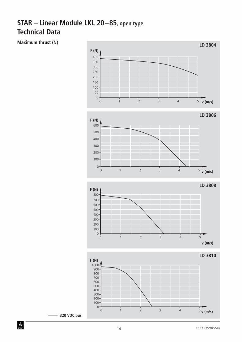
LD 3810 LD 3808 LD 3806 LD 3804 LD2510 LD 2508 LD 2506 LD 2504
Peak thrust (N) 990 780 580 380 470 375 280 180
Peak speed (m/s) 2.6 3.2 4.5 6.5*) 5.2*) 6.5*) 8*) 11*)
Peak acceleration (m/s2) 148 134 120 101 146 138 126 115
Force constant (N/A) 99 79 58 38 47 38 28 19
Continuous current (A) 3 3.09 3.24 3.57 2.67 2.82 3.05 3.22
Continuous thrust at 20°C (N) 297 244 188 136 125 109 85 61
Counter-emf constant (V/m/s) 115 91 68 44 55 44 33 22
Phase-to-phase resistance at 20°C (Ω) 16.4 13.5 10 6.7 13.4 10.8 8.2 5.4
Min. phase-to-phase inductance (mH) 17.4 14.6 11.9 7.5 11.7 8.3 6.2 4.2
Electrical time constant of motor (ms) 1.06 1.08 1.19 1.12 0.87 0.77 0.76 0.76
1) Excluding the mass of cables and the input power cable protective chain (0.6 kg/m).2) Carriage without input power cable protective chain and bellows.
Protection IP 54Max. operating temperature 80°C. *) Maximum speed 5 m/s - limited by Ball Rail System.
Technical Data
Linear Motor Carriage Dynamic load Dynamic moment Moved Maximum Planar moment of inertia Frict. NumberModule length capacity C Mt ML mass1) length Lmax lx ly drag2) of runner
(mm) (N) (Nm) (Nm) (kg) (mm) (cm4) (cm4) (N) blocks
LD 2504 119 6000 57 31 1.5 7.5 1
LKL 15-70 LD 2506 170 6820 64 434 2.11600 11.05 57.44
15 2
LD 2508 221 6820 64 608 2.6 15 2
LD 2510 272 6820 64 730 3.1 15 2
LD 3804 163 15590 194 846 3.5
LKL 20-85LD 3806 234 23550 308 1483 4.6
2000 15.93 105.40 26 2LD 3808 305 23550 308 2673 5.6
LD 3810 376 23550 308 3509 6.5
, open type
Control signals via digital controller DKC**.3 (1 x 230 V connection)(see catalog RE 82 701 “Controllers, Motors, Electrical Accessories”)
STAR – Linear Modules LKL

11RE 82 425/2000-02
Structure1 Frame
2 Carriage
3 Thrust rod
4 End block
5 Guide rail
6 Guideway end plate(only LKL 15-70 with L > 600 mm,LKL 20-85 with L > 800 mm)
7 Buffer (for option without bellows)8 Bellows
Attachments:
9 Power cable chain
10 Socket/plug
11 Proximity switch
11a Reference switch/proximity switch
12 Switching cam
13 Cable duct
Cable set:
14 Linear encoder
15 Hall effect sensor
16 Motor cable
MassMass calculation does not include switches
Mass formula:
Mass (kg/mm) · length L (mm) + mass ofall parts of fixed length (carriage, etc.) (kg)
119 0.0079 · L + 2.17
LKL 15-70 170 0.0079 · L + 2.77
221 0.0079 · L + 3.27
272 0.0079 · L + 3.77
163 0.0138 · L + 4.42
LKL 20-85234 0.0138 · L + 5.52
305 0.0138 · L + 6.52
376 0.0138 · L + 7.42
Linear Module Carriage length Mass(mm) (kg)
11
11a
11
128
4
13
4
103
5
9
LS100-XXXX
2
6
7
6
1
14
1516
Bellows:
max. speed 3 m/smax. length 1600 mm
Non-compliance with the above valuesmay result in premature failure.

12 RE 82 425/2000-02
STAR – Linear Module LKLTechnical DataMaximum thrust (N)
15–70, open type
LD 2504
LD 2506
LD 2508
LD 2510
0 1 2 3 4 50
100
200
150
50
v (m/s)
0 1 2 3 4 50
100
200
300
250
150
50
v (m/s)
F (N)
F (N)
100
0 1 2 3 4 50
200
300
400
v (m/s)
F (N)
200
400
0 1 2 3 4 50
100
300
500
v (m/s)
F (N)
320 VDC bus

13RE 82 425/2000-02
Time vs. Displacement curvesfor horizontal operation withvarying payloads, determinedat 25% duty cycle
In preparation
LD 2504
200
0200 4000
400t (ms)
100 300 500 600 700 800 900 1000
100
300
1 kg2 kg5 kg
10 kg
Hub(mm)
50
150
250
350
LD 2506
200
0200 4000
600t (ms)
100 300 500 600 700 800
100
400
1 kg
5 kg
15 kg
300
500
10 kg
20 kg
900 1000 Hub(mm)
LD 2508
400
0200 4000
t (ms)
Hub(mm)
100 300 500 600 700 800 900 1000
200
600
1 kg5 kg
30 kg
10 kg
20 kg
100
300
500
LD 2510
Stroke(mm)
Stroke(mm)
Stroke(mm)
14 RE 82 425/2000-02
STAR – Linear Module LKLTechnical DataMaximum thrust (N)
20–85, open type
LD 3804
LD 3806
LD 3810
LD 3808
v (m/s)
F (N)
0 1 2 3 4 50
100
200
300
400
150
250
350
50
300
400
500
600
0 1 2 3 4 50
100
200
v (m/s)
F (N)
2
400
500
600
700
0 1 3 4 50
100
200
300
800
v (m/s)
F (N)
200300400
600700
900
0 1 2 3 4 50
100
500
800
1000
v (m/s)
F (N)
320 VDC bus
Linear Module LKL

15RE 82 425/2000-02
Time vs. Displacement curvesfor horizontal operation withvarying payloads, determinedat 25% duty cycle
LD 3804
300
0200 4000
t (ms)
Hub(mm)
100 300 500 600 700 800 900 1000
200
10 kg15 kg
100
400 20 kg
5 kg1 kg
LD 3806
400
0200 4000
t (ms)
Hub(mm)
100 300 500 600 700 800 900 1000
200
100
500
300
600
1 kg
40 kg30 kg
10 kg5 kg
20 kg
LD 3808
400
0200 4000
t (ms)
Hub(mm)
100 300 500 600 700 800 900 1000
200
100
500
300
600
1 kg
10 kg5 kg
20 kg
40 kg30 kg
LD 3810
400
0
t (ms)
Hub(mm)
200
500
300
700
600
800
100
200 4000 100 300 500 600 700 800 900 1000
1 kg
10 kg5 kg
40 kg30 kg20 kg
Stroke(mm)
Stroke(mm)
Stroke(mm)
Stroke(mm)

16 RE 82 425/2000-02
STAR – Linear Module LKLComponents and Ordering Data
Ordering data
Order example
Description
Linear Module, open typeLKL 15-70, length (L) = 950 mmLength of cable set = 3500 mmwith drive unitball rail systemmotor LD2508carriage with length LT = 251 mmwith flexible protective chainPU bellowsmagnetic encoderPNP NCPNP NCPNP NOcable ductsocket/plug on switch sidewith switching cam for switch activationmeasurement report: frictional drag
01
01
00OA01
without drive unit (OA)
Linear Module LKL(Part number): 0355-400-00 950 mmLength of cable set = 3500 mmType = MA01Guideway = 01Drive unit = 03Carriage = 03Power input cable = 01Cover = 01Linear encoder = 011st switch = 112nd switch = 113rd switch (reference) = 13Cable duct = 20Socket/plug = 17Switching cam = 16Documentation = 02
with drive unit (MA)
(03.45.00)
LT = 119 mm
LT = 170 mm
LT = 221 mm
11
12
13
Switches
Power input cable
MA01
(03.45.10)
MA02
(03.45.11)
MA03
(03.45.12)
MA04
(03.45.13)
LD 2506 02
02LT = 170 mm
for L > 600LT = 200 mm
LD 2508 0303
For controller and servo amplifier see “Controllers” catalog*Specify length of cable set in increments of 0.5 m measured from the cable exit on the frame,
max. cable length 18 m (for longer lengths, please consult us)
LD 2504 01
01LT = 119 mm
for L > 600LT = 149 mm
15–70, open type
LD 2510 04
LT = 272 mm 14
04LT = 272 mm
for L > 600LT = 302 mm
06
07
08
09
LT = 221 mm
for L > 600LT = 251 mm
L T
Part number Type .... Guideway .. Drive unit .. Carriage ..(and dimension
drawing)0355-400-00, .... mm
Length of cable set .... mm*

17RE 82 425/2000-02
Frictionaldrag
Position-ing
accuracy
02
05
01 00
Please check that the selected combination is a permissible one(load capacities and moments, motor data, etc.)!
* Supplied unmounted along with the module
01
without 00
without 00
with 01
Effective strokeEffective stroke = max. travel - 2 · excess travel
Calculating the linear module length L
With bellows– max. speed 3 m/s– Non-compliance with the values indi-
cated may result in premature failure.
Length L = (stroke + 2 · excess travel) + carriage length1) LT + 40 mmWithout bellows
See dimension drawing for effective stroke,excess travel, carriage length LT
without00
0200
without 00
Switches*:
PNP NC 11
PNP NO 13
Cable duct* length = L 20
Socket/plug* 17
Switching cam* 16
without 00
magnetic 01
If the linear module is to operate reliably,the excess travel must be greater than thebraking distance.
The braking distance can be assumed tobe equal to the acceleration distance.
We recommend that customers mountshock absorbers at the mass center ofgravity to reduce excess travel.
Length L = (stroke + 2 · excess travel) · 1.372 + carriage length1) LT + 39 mm
1) Please note: When L > 600, carriage will be longer.
Power input Cover .. Linear encoder .. 1st, 2nd switch .. Documentation ..cable ..
PU Socket/plug .. Standard Measure-bellows Switching cam .. report ment
Cable duct .. report
without

18 RE 82 425/2000-02
STAR – Linear Module LKL
15* 15*
L2
L2
LT
20
6987
.5
L
Dimension Drawings
03.45.1103.45.1003.45.00
Lube nipple
4
88
69
Cable exit
Standard mounting
Type MA01
Overhead mounting
Type MA02Type OA01
Cable exitat back
Cable exitat back
15–70, open type
Excess
travel
Max. travel2
Effective stroke2
Effective stroke2
Max. travel2
Useful carriage length
* Guideway end plate at both ends when L > 600 mm (please note carriage option number).
Excess
travel

19RE 82 425/2000-02
A
90
61
35
25
50
70
BC
68 26
C
4.8
5.2
6.7
B
4.8 2.5
2.5
8.2
5.2
5
A
11
6.2
6.2
5.3
03.45.12 03.45.13Left-hand mounting
Type MA03Right-hand mounting
Type MA04
Cable exitat back
Cable exitat back
For mounting of power cable chain, see chapter “Power Cable Chain”
STSTARAR
STSTARAR

20 RE 82 425/2000-02
STAR – Linear Module LKL
Ordering data Description
Components and Ordering Data
Order example
01
01
00OA01
without drive unit (OA)
with drive unit (MA)
(03.55.00)
LT = 163 mm
LT = 234 mm
LT = 305 mm
11
12
13
Switches
Power input cable
MA01
(03.55.10)
MA02
(03.55.11)
MA03
(03.55.12)
MA04
(03.55.13)
LD 3806 0202LT = 234 mm
for L > 800LT = 264 mm
LD 3808 0303LT = 305 mm
for L > 800LT = 335 mm
LD 3804 01
20–85, open type
LT = 376 mm 14
LD 3810 0403LT = 376 mm
for L > 800LT = 406 mm
LT = 163 mm
for L > 800LT = 193 mm
L T
Part number Type .... Guideway .. Drive unit .. Carriage ..(and dimension
drawing)0355-500-00, .... mm
Length of cable set .... mm*
01
06
07
08
09
Linear Module LKL(Part number): 0355-500-00 950 mmLength of cable set = 2000 mmType = MA01Guideway = 01Drive unit = 03Carriage = 02Power input cable = 01Cover = 01Linear encoder = 011st switch = 112nd switch = 113rd switch (reference) = 13Cable duct = 20Socket/plug = 17Switching cam = 16Documentation = 02
Linear Module, open typeLKL 20-85, length (L) = 950 mmLength of cable set = 2000 mmwith drive unitball rail systemmotor LD3808carriage with length LT = 264 mmwith flexible protective chainPU bellowsmagnetic encoderPNP NCPNP NCPNP NOcable ductsocket/plug on switch sidewith switching cam for switch activationmeasurement report: frictional drag
For controller and servo amplifier see “Controllers” catalog*Specify length of cable set in increments of 0.5 m measured from the cable exit on the frame,
max. cable length 18 m (for longer lengths, please consult us)

21RE 82 425/2000-02
Frictionaldrag
Position-ing
accuracy
02
05
0100
Please check that the selected combination is a permissible one(load capacities and moments, motor data, etc.)!
* Supplied unmounted along with the module
01
without 00
without 00
with 01
With bellows– max. speed 3 m/s– max. length 1600 mm– Non-compliance with the values indi-
cated may result in premature failure.
without 00
02
without 00
Switches*:
PNP NC 11
PNP NO 13
Cable duct* length = L 20
Socket/plug* 17
Switching cam* 16
without 00
magnetic 01
Effective strokeEffective stroke = max. travel - 2 · excess travel
Length L = (stroke + 2 · excess travel) + carriage length1) LT + 40 mmWithout bellows
See dimension drawing for effective stroke,excess travel, carriage length LT
Calculating the linear module length L
If the linear module is to operate reliably,the excess travel must be greater than thebraking distance.
The braking distance can be assumed tobe equal to the acceleration distance.
We recommend that customers mountshock absorbers at the mass center ofgravity to reduce excess travel.
Length L = (stroke + 2 · excess travel) · 1.372 + carriage length1) LT + 39 mm
Power input Cover .. Linear encoder .. 1st, 2nd switch .. Documentation ..cable ..
PU Socket/plug .. Standard Measure- bellows Switching cam .. report ment
Cable duct .. report
00
1) Please note: When L > 800, carriage will be longer.
without

22 RE 82 425/2000-02
STAR – Linear Module LKL
L2L2
L2
15* 15*
LT
107.
584
20
L
Dimension Drawings 20–85, open type
03.55.1103.55.1003.55.00Standard mounting
Type MA01Overhead mounting
Type MA02
Cable exitat back
Lube nipple
4
108
84
Cable exit
Type OA01
Cable exitat back
Max. travel2
Effective stroke2
Max. travel2
Effective stroke2Excess
travelExcesstravel
Useful carriage length
* Guideway end plate at both ends when L > 800 mm (please note carriage option number).
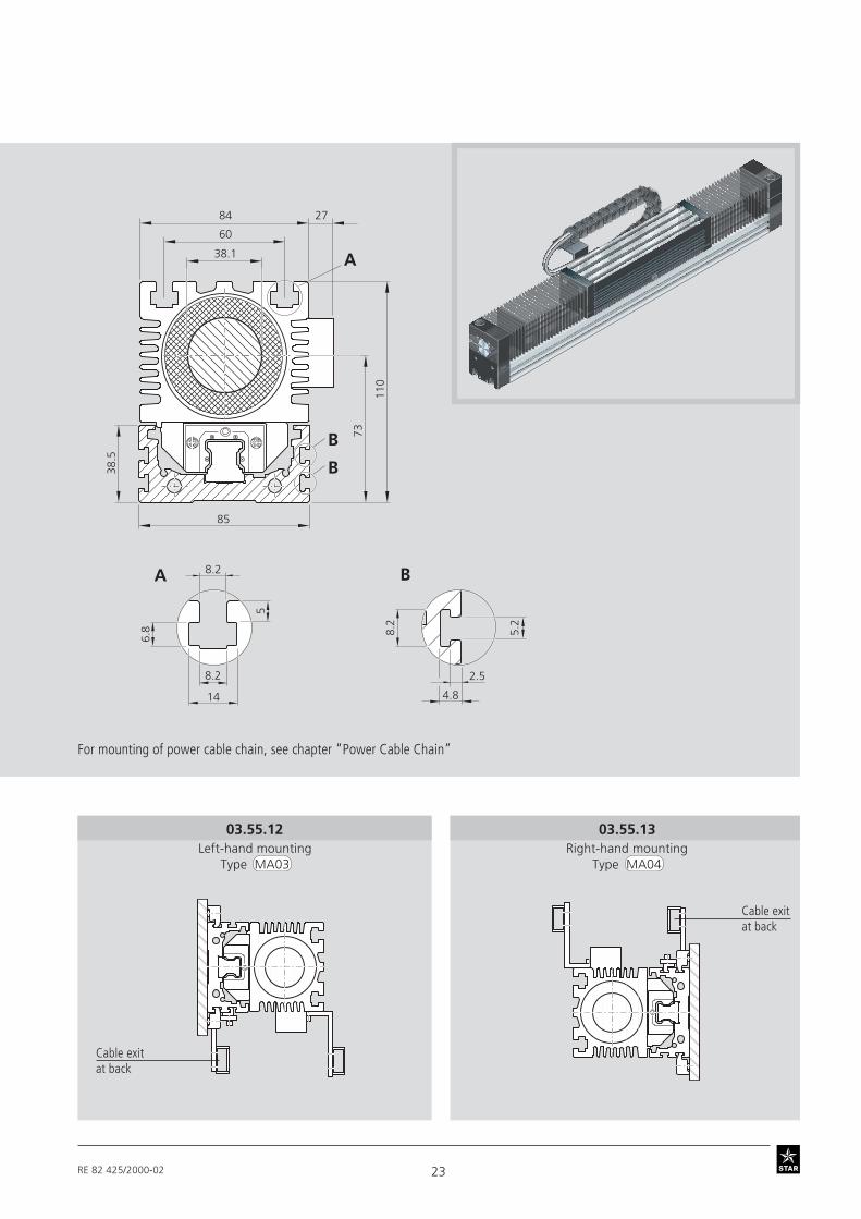
23RE 82 425/2000-02
B
4.8
2.5
8.2
5.2
5
A
14
8.2
8.2
6.8
38.1
38.5
110
73
85
A
B
B
60
84 27
03.55.12 03.55.13Left-hand mounting
Type MA03Right-hand mounting
Type MA04
Cable exitat back
Cable exitat back
For mounting of power cable chain, see chapter “Power Cable Chain”
24 RE 82 425/2000-02
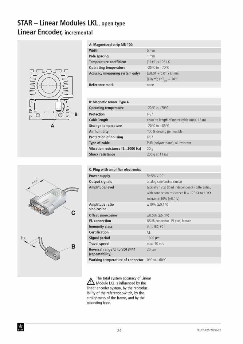
STAR – Linear Modules LKLLinear Encoder, incremental
, open type
B
A
ø 5
≈33
LS100-XXXX
XX XXXX
C
B
A: Magnetized strip MB 100
Width 5 mm
Pole spacing 1 mm
Temperature coefficient (11±1) x 10-6 / K
Operating temperature -20°C to +70°C
Accuracy (measuring system only) (±0.01 + 0.01 x L) mm
[L in m]; at Tamb = 20°C
Reference mark none
C: Plug with amplifier electronics
Power supply 5±5% V DC
Output signals analog sine/cosine similar
Amplitude/level typically 1Vpp (load independent) - differential,
with connection resistance R = 120 Ω to 1 kΩtolerance 10% (±0.1 V)
Amplitude ratio ±10% (±0.1 V)sine/cosine
Offset sine/cosine ±0.5% (±5 mV)
El. connection DSUB connector, 15 pins, female
Immunity class 3, to IEC 801
Certification CE
Signal period 1000 µm
Travel speed max. 50 m/s
Reversal range U, to VDI 3441 20 µm(repeatability)
Working temperature of connector 0°C to +60°C
The total system accuracy of LinearModule LKL is influenced by the
linear encoder system, by the reproduc-ibility of the reference switch, by thestraightness of the frame, and by themounting base.
B: Magnetic sensor Type A
Operating temperature -20°C to +70°C
Protection IP67
Cable length equal to length of motor cable (max. 18 m)
Storage temperature -20°C to +85°C
Air humidity 100% dewing permissible
Protection of housing IP67
Type of cable PUR (polyurethane), oil-resistant
Vibration resistance [5...2000 Hz] 20 g
Shock resistance 200 g at 11 ms
25RE 82 425/2000-02
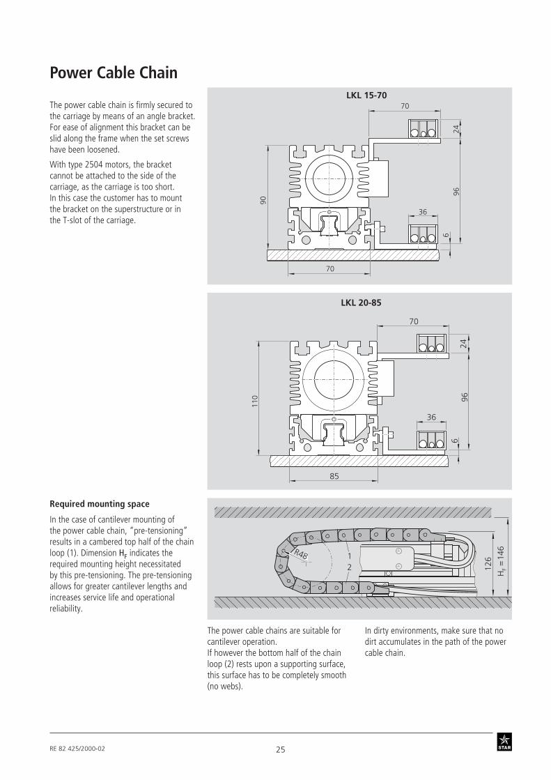
126 14
6R48 12
HF =
70
24
36
6
90
96
LKL 15-70
70
Power Cable Chain
The power cable chain is firmly secured tothe carriage by means of an angle bracket.For ease of alignment this bracket can beslid along the frame when the set screwshave been loosened.
With type 2504 motors, the bracketcannot be attached to the side of thecarriage, as the carriage is too short.In this case the customer has to mountthe bracket on the superstructure or inthe T-slot of the carriage.
70
24
36
696
110
LKL 20-85
85
Required mounting space
In the case of cantilever mounting ofthe power cable chain, “pre-tensioning”results in a cambered top half of the chainloop (1). Dimension HF indicates therequired mounting height necessitatedby this pre-tensioning. The pre-tensioningallows for greater cantilever lengths andincreases service life and operationalreliability.
The power cable chains are suitable forcantilever operation.If however the bottom half of the chainloop (2) rests upon a supporting surface,this surface has to be completely smooth(no webs).
In dirty environments, make sure that nodirt accumulates in the path of the powercable chain.

26 RE 82 425/2000-02
STAR – Linear Modules LKL
Switching system overview1 Socket/plug
2 Proximity switches(with mounting accessories)
2a Reference switch/proximity switch
3 Cable duct (aluminum alloy)
4 Switching cam
Miniature switch with potted cable(3 x 0.14 mm2 Unitronic)Switch housing type = NOMini sensor = Type A DIN 41635Operating voltage = 10 to 30 V DCResidual ripple factor = ≤ 10%Load = 200 mAIdling current = ≤ 20 mASwitching frequency = max. 1500 HzTemperature sensitivity ofcut-in point = ≤ 4 µm/KSlope ofoutput signal = ≥ 1V/µs
Reproducibility ofcut-in point to EN 50008 = ≤ 0.1 mm
Proximity switch (technical data)
Cabl
e le
ngth
: 3 m
Proximity switch with mounting plate
30
355
45
7
22
1719 10
SwitchesMounting instructions:
The switches are supplied loose.
Switches may only be mounted on oneside of the linear module (opposite thepower input cable). Do not mount theswitches until the linear module hasbeen fixed to its base.
Insert the plate-mounted switches in theT-slots in the frame and fix them with twoset screws.
The switching cam may only bemounted on the carriage end
furthest away from the socket. Adjustthe switching gap from 0.1 to 0.2 mmon mounting.
20
0.1+
0.1
2a2
1
4
2
Switching cam SocketCarriage end
Switch Mounting, open typeLinear Modules LKL

27RE 82 425/2000-02
Cable duct– Clip the duct into the T-slot in the
frame and fix it in place with themounting screw.
– Mounting screws and cablegrommets are provided.
17
20
503 4.5
ø 26
27.5
28.5
49
60
16-pin plug
Socket and plug– Fix the socket to the side with
the switches.
The socket and plug have 16 pins each.
The socket and switches are not wired.The switch activation points can thus beoptimized during start-up.
A plug is provided.
The plug can be mounted in threedirections (see figure).
Part numbers
Item
1 Socket-plug 0399-800-702 Proximity switch
- mounting accessories without switch 1175-001-52- PNP NC 8453-040-01- NPN NC 8453-040-02- PNP NO 8453-040-03- NPN NO 8453-040-04
3 Cable duct 0399-800-064 Switching cam 0399-800-71
Ordering switches andmounting accessories
The part numbers are listed in the table.
Mounting accessories can be orderedseparately.

28 RE 82 425/2000-02
STAR – Linear Modules LKLMounting Instructions
, open type
Clamping fixtures
Recommended number of clamping fixtures: with 1 hole, 6 per meter and sidewith 4 holes, 3 per meter and sidewith 2 holes, 4 per meter and side
Tightening torques for mounting screwswith friction factor 0.125
strength class 8.8
General informationThe linear module is mounted usingspecial clamping fixtures.
When mounting the linear modules,observe the maximum tightening torquesas indicated in the table.
Mounting with clamping fixtures
Do not fix the linear module bythe end blocks!
The frame is the main stress-bearingstructure!Wherever possible, it has to be sup-ported over its entire length.
The flatness of the supporting surfacemust be of the required accuracy.
Size A B(mm) (mm)
15-70 86 10020-85 101 115
Recess for M5ISO 4762
A
B
±0.1
Recess for M6ISO 4762T L
7
19.3 3.4
11.5
0375-510-000375-410-02 0375-510-020375-510-09
Part numbers
8.8 M5 M6
5.5 9.5Nm
A B C D
Recess for M6ISO 4762
T = 50 L = 72
0375-510-11
T = 40 L = 62
7
19.3 5.5
11.5
8.5
3030
30
107
1140
4040
142
25
Linear Modules LKL

29RE 82 425/2000-02
to DIN 508
Square nutsto DIN 557
Size 15–70 Größe 20-85
Part number
8442-003-00
Mounting accessories forcarriage superstructure
T-nuts Size 15–70
Part number
M4: 8447-004-01M5: 8447-005-01
Size 20–85
Part number
8447-001-01
Part number
0391-750-03
Size 20–85
Part number
8442-004-00
6
4 8
M..
10
8
6 10
M6
13
M8
6.5
13
13M6
8
106
209
(2x)
M6
5
10

30 RE 82 425/2000-02
STAR – Linear Modules LKLDocumentation
, open type
Positioning accuracyOption 05
to VDI/DGQ 3441
Measurement points are selected atirregular intervals along the travel. Thisallows even periodical deviations to bedetected during positioning.
Each measurement point is approachedseveral times from both sides.
This gives the following parameters:
Positioning accuracy P
The positioning accuracy corresponds tothe total deviation.
It encompasses all the systematic andrandom deviations during positioning.
The positioning accuracy takes thefollowing characteristic values intoconsideration:
– position deviation– reversal range– position variation range
Reversal range U
Position variation range PS
Devi
atio
n (µ
m)
Example
Set position (mm)
Position deviation Pa
175 252.5 350 612.5 700
25
0
-25
-50
-75
-1000 87.5 437.5 525
P a
P
Ps/
2P
s/2
U
The position deviation corresponds to themaximum difference arising in the meanvalues of all the measurement points. Itdescribes systematic deviations.
The reversal range corresponds to thedifference in mean values of the twoapproach directions. The reversal range isdetermined at every measurement point. Itdescribes systematic deviations.
The position variation range describesthe effects of random deviations. It isdetermined at every measurement point.
Standard reportOption 01
The standard report serves to confirm thatthe checks listed in the report have beencarried out and that the measured valueslie within the permissible tolerances.
Checks listed in the standard report:
– functional checks of mechanicalcomponents
– functional checks of electricalcomponents
– design is in accordance with orderconfirmation
Frictional dragOption 02
The moment of friction is measured overthe entire travel range.
Linear Modules LKL

31RE 82 425/2000-02
To be completed by customer: Inquiry / OrderLinear Module
(Part number): ______ - ______ - ______, length ________ mmLength of cable set = __________ mmType =
Guideway =
Drive unit =Carriage =Power input cable =Cover =Linear encoder =1st switch =2nd switch =3rd switch (reference) =Cable duct =Socket/plug =Switching cam =Documentation =
STAR – Linear Modules LKL, open type
Inquiry/Order Form
Order example: Linear Module LKL 15-70, open type
STAR Linear Modules
Ordering data Description
Quantity ____ pcs, _____ per month, ______ per year, per order, or_________________Remarks:
FromCompany: ______________________________________ Name: ____________________________________
Address: ______________________________________ Department: ____________________________________
______________________________________ Telephone: ____________________________________
______________________________________ Telefax: ____________________________________
Rexroth Star GmbH
D-97419 Schweinfurt
Linear Module, open typeLKL 15-70, length (L) = 950 mmLength of cable set = 3500 mmwith drive unitball rail systemMotor LD2508carriage with length LT = 251 mmwith flexible protective chainPU bellowsmagnetic encoderPNP NCPNP NCPNP NOcable ductsocket/plug on switch sidewith switching cam for switch activationmeasurement report: frictional drag
Linear Module LKL(Part number): 0355-400-00, 950 mmLength of cable set = 3500 mmType = MA01Guideway = 01Drive unit = 03Carriage = 03Power input cable = 01Cover = 01Linear encoder = 011st switch = 112nd switch = 113rd switch (reference) = 13Cable duct = 20Socket/plug = 17Switching cam = 16Documentation = 02
Telephone +49-9721-937-0
Telefax +49-9721-937-275(general)
Telefax +49-9721-937-350(direct)

Great care has been taken during the compilation ofthis publication to ensure all the information containedis accurate. We accept no responsibility however forany damage resulting from incorrect or incompleteinformation contained.
For deliveries and other services in the course of com-mercial business, the general terms and conditions forsupplies and services contained in the valid price listsand the confirmations of order apply.
As our products are constantly in the process of furtherdevelopment, they are subject to alteration withoutnotice.
STAR, Ball Rail and are trademarks registered forRexroth Star GmbH, Germany.
Roller Rail is a trademark ofRexroth Star GmbH, Germany.
This publication or any part thereof may not bereproduced without our written permission.
Prin
ted
on c
hlor
ine-
free
blea
ched
pap
er
Rexroth Star GmbHD-97419 SchweinfurtGermany
Telephone +49-9721-937-0
Telefax +49-9721-937-275(general)
Telefax +49-9721-937-250(direct)
www.rexroth-star.com
Linear Modules LKLopen typeRE 82 425/2000-02
Printed in Germany - p 2000
REG. NO.1617 - 03