Embed Size (px)
Citation preview

STANDARD OPERATING PROCEDURES
SOP : 1720
PAGE: 1 of 55
REV: 1.0
DATE: 01/20/06
OPERATION OF THE NITON XLt792YW FIELD PORTABLE
X-RAY FLUORESCENCE INSTRUMENT
CONTENTS
1.0 SCOPE AND APPLICATION*
2.0 METHOD SUMMARY
3.0 SAMPLE PRESERVATION, CONTAINERS, HANDLING, AND STORAGE*
4.0 INTERFERENCES AND POTENTIAL PROBLEMS*
5.0 EQUIPMENT/APPARATUS
5.1 Description of the NITON XLt792YW System*
5.2 Equipment and Apparatus List
5.2.1 NITON XLt792YW Analyzer System
5.2.2 Optional Items
5.3 Peripheral Devices
5.3.1 Communication Cable Connection
5.3.2 NITON Xlt 700 Series Software
6.0 REAGENTS*
7.0 PROCEDURES
7.1 Instrument Operation
7.1.1 Startup
7.1.2 Precautions*
7.2 Control Panel and Menu Software
7.2.1 The Control Panel
7.2.2 The Menu System*
7.2.3 The Main Menu
7.2.4 The Mode Menu
7.2.5 The Utilities Menu
7.2.6 The Calibrate Menu*
7.2.7 The Data Menu
7.2.8 The Erase Menu
7.2.9 The Common Setup Menu
7.2.10 The Set Protocol Menu and Sub Menus
7.2.10.1 The Filter Menu
7.2.10.2 The Filter Time Menu
7.2.11 Standard Soil Mode
7.2.12 The Results Screen

STANDARD OPERATING PROCEDURES
SOP : 1720
PAGE: 2 of 55
REV: 1.0
DATE: 01/20/06
OPERATION OF THE NITON XLt792YW FIELD PORTABLE
X-RAY FLUORESCENCE INSTRUMENT
CONTENTS (cont)
7.3 Preoperational Checks
7.3.1 Energy Calibration
7.3.2 Resolution Check*
7.3.3 Blank (Zero) Sample Check*
7.3.4 Target Element Response Check*
7.4 Filter Measuring Time
7.5 Sample Handling and Presentation
7.5.1 Soil Samples
7.5.2 Thin (Filter) Samples
7.6 Downloading Stored Results and Spectra
7.7 Instrument Maintenance*
7.7.1 Exterior Cleaning
7.7.2 Further Information and Troubleshooting
7.8 Reporting Results*
8.0 CALCULATIONS
9.0 QUALITY ASSURANCE/QUALITY CONTROL
9.1 Calibration
9.2 Resolution Check
9.3 Blank Check
9.4 Precision*
9.5 Method Detection Limit and Reporting Limit*
9.6 Accuracy
9.7 Confirmation Analysis*
9.8 Matrix Considerations*
10.0 DATA VALIDATION
10.1 Screening Data
10.2 Screening Data with Definitive Confirmation*
11.0 HEALTH AND SAFETY
12.0 REFERENCES
STANDARD OPERATING PROCEDURES
SOP : 1720
PAGE: 3 of 55
REV: 1.0
DATE: 01/20/06
OPERATION OF THE NITON XLt792YW FIELD PORTABLE
X-RAY FLUORESCENCE INSTRUMENT
CONTENTS (cont)
13.0 APPENDICES*
A - Principles of Operation
B - Figures
C - Certified SRM Values and Certificates of Analysis*
D - Sample Preparation for FPXRF Analysis*
E - Typical MDL Values for the NITON XLt792YW FPXRF Analyzer*
14.0 BIBLIOGRAPHY
* These sections affected by Revision 1.0
SUPERCEDES: SOP #1720; Revision 0.0; 11/22/05; U.S. EPA Contract EP-W-09-031.

STANDARD OPERATING PROCEDURES
SOP : 1720
PAGE: 4 of 55
REV: 1.0
DATE: 01/20/06
OPERATION OF THE NITON XLt792YW FIELD PORTABLE
X-RAY FLUORESCENCE INSTRUMENT
1.0 SCOPE AND APPLICATION
The purpose of this Standard Operating Procedure (SOP) is to outline the steps required for the start-up, check out,
operation, calibration, and routine use of the NITON Xlt 792YW field-portable x-ray fluorescence (XRF) instru-
ment. The data generated using this SOP meets the Screening Data objective for a quick, preliminary assessment
of site contamination, and provides preliminary analyte identification and quantification. Screening data without
associated confirmation data are generally not considered to be data of known quality. This SOP supplements the
NITON Xlt 700 Series Environmental Analyzer User’s Guide (NITON 2004) that contains detailed information for
optimizing instrument performance and for utilizing different applications. The principles of operation are detailed
in Appendix A.
Solid and liquid samples may be analyzed with the NITON XLt792YW for elements potassium (K) through
uranium (U) with proper X-ray tube/filter selection, application setup, measurement conditions, and instrument
calibration. Typical environmental applications include:
Heavy metals in soil (in-situ or samples collected from the surface or from bore hole drillings), sediments, and
sludges.
Heavy metal air particulates collected on membrane filters, either from personnel samplers or from high
volume samplers.
The manufacturer recommends operating within a temperature range of 20 to 120 degrees Fahrenheit ( F).
2.0 METHOD SUMMARY
Miniaturized X-ray tube technology is used by the NITON XLt792YW XRF instrument for the production of
primary X-rays. This technology combined with multiple programmable primary excitation filters, eliminates the
need for multiple radioisotope sources. Each filter transmits a specific range of primary X-rays, which excite a
corresponding range of elements in a sample.
A sample is positioned in front of the X-ray tube/detector window and sample measurement is initiated. This
exposes the sample to filtered primary radiation. Fluorescent and backscattered X-rays from the sample enter
through the detector window and are counted by the high-performance, solid-state detector.
Elemental concentrations are computed based on ratios of analyte X-ray intensity to backscatter. The raw ratios are
corrected for spectral overlap and inter-element effects. The NITON XLt792YW is factory calibrated, and the
menu-driven software supports multiple calibrations called "test modes." Each test mode is a complete analysis
configuration including elements to be measured, interfering elements in the sample, and a set of calibration
coefficients. The manufacturer states that the “Standard Soil Mode” for the NITON XLt792YW may be used
when: 1) the percentage of the elements of interest are less than (<) 1.0%, 2) the material is of a light matrix (for
example, aluminum silicate), and 3) elements with atomic number greater than iron do not exceed several percent.
Measurement time is user controlled. Shorter measurement times (30 - 60 seconds [s]) are generally used for initial
screening and hot spot delineation, while longer measurement times (60 - 300s) are typically used for higher
precision and accuracy requirements.

STANDARD OPERATING PROCEDURES
SOP : 1720
PAGE: 5 of 55
REV: 1.0
DATE: 01/20/06
OPERATION OF THE NITON XLt792YW FIELD PORTABLE
X-RAY FLUORESCENCE INSTRUMENT
3.0 SAMPLE PRESERVATION, CONTAINERS, HANDLING AND STORAGE
Refer to Section 7.5, Sample Handling and Presentation.
4.0 INTERFERENCES AND POTENTIAL PROBLEMS
Total method error for XRF analysis is a combination of both instrument precision and user- or application-related
error. Instrument precision is typically the least significant source of error in XRF analysis. User- or application-
related error is generally more significant and will vary with each site and method used. The following examples of
user or application-related errors are discussed below:
Sample Placement - This is a potential source of error because the X-ray signal decreases as the distance from
the X-ray source is increased. This error may be minimized by maintaining the same distance for each sample.
Sample geometry with respect to the X-ray tube/detector is also important. A tilted sample may cause
analytical error. The NITON Xlt792YW ratios analyte X-ray lines to backscatter, which minimizes this type
of error.
Sample Representivity - To accurately characterize site conditions, samples collected must be representative of
the site or area under investigation. Representative soil sampling ensures that a sample or group of samples
accurately reflects the concentration of the contaminant(s) of concern at a given time and location. Analytical
results from representative samples reflect the variation in pollutant presence and concentration range
throughout a site. Variables affecting sample representativeness include: (1) geologic variability, (2)
contaminant concentration variability, (3) collection and preparation variability, and (4) analytical variability.
Attempts should be made to minimize these sources of variability. For additional information on
representative sampling, refer to "Removal Program Representative Sampling Guidance, Volume 1 - Soil.”
(U.S. EPA/ERT 1991).
Reference Analysis - Soil chemical and physical matrix effects may be corrected (to some extent) by adjusting
XRF results (via regression) using site-specific soil samples which have been analyzed by Inductively-Coupled
Plasma (ICP) or Atomic Absorption (AA) spectroscopy methods. A major source of error can result if these
samples are not representative of the site and/or if the analytical error is large. Additionally, when comparing
XRF results with reference analyses results, the efficiency of the sample digestion reference analysis should be
considered. Some digestion methods may breakdown different sample matrices more efficiently than others.
Chemical Matrix Effects - Chemical matrix effects result from differences in concentrations of interfering
elements. These effects appear as either spectral interferences (peak overlaps) or as X-ray
absorption/enhancement phenomena. Both effects are common in soils contaminated with heavy metals. For
example, iron (Fe) tends to absorb copper (Cu) X-rays, reducing the intensity of Cu measured by the detector.
This effect can be corrected mathematically through the use of inter-element correction coefficients.
Physical Matrix Effects - Physical matrix effects are the result of variations in the physical character of the
sample and include parameters such as particle size, uniformity, homogeneity, and surface condition. For
example, consider a sample in which the analyte exists in the form of very fine particles within a matrix
composed of much coarser material. If two separate aliquots of the sample are prepared in such a way that the
matrix particles in one are much larger than in the other, then the relative volume of analyte occupied by the
analyte-containing particles will be different in each. When measured, a larger amount of the analyte will be

STANDARD OPERATING PROCEDURES
SOP : 1720
PAGE: 6 of 55
REV: 1.0
DATE: 01/20/06
OPERATION OF THE NITON XLt792YW FIELD PORTABLE
X-RAY FLUORESCENCE INSTRUMENT
exposed to the source X-rays in the sample containing finer matrix particles, resulting in a higher intensity
reading for that sample and, consequently, an apparently higher measured concentration for that element.
Application Error - Generally, the error in the application calibration model is insignificant (relative to the
other sources of error) PROVIDED the instrument's operating instructions are followed correctly. However,
if the sample matrix varies significantly from the design of the application, the error may become significant
(e.g., using the Standard Soil Mode application to analyze a 50% iron mine tailing sample).
Moisture Content - Sample moisture content affects the analytical accuracy of soils or sludges. The overall
error may be secondary when the moisture range is small (5 to 20%), or it may be a major source of error
when measuring the surface of soils that are saturated with water. NOTE: Attempting an in-situ measurement
on a saturated soil may damage the instrument.
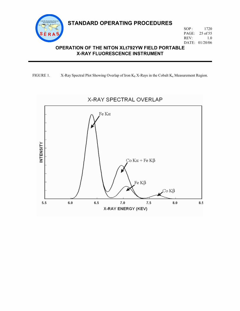
Cases of Severe X-ray Spectrum Overlaps - When present in the sample, certain X-ray lines from different
elements can be very close in energy and therefore, can interfere by producing a severely overlapped spectrum.
Typical spectral overlaps are caused by the K-beta (Kβ) line of element Z-1 (or as with heavier elements, Z-2
or Z-3) overlapping with the K-alpha (Kα) line of element Z. This is the so-called Kα/Kβ interference. Since
the Kα:Kβ intensity ratio for the given element usually varies from 5:1 to 7:1, the interfering element, Z-1, must
be present in large concentrations in order to affect the measurement of analyte Z. For example, the presence
of large Fe concentrations could affect the measurement of cobalt (Co). The Fe Kα and Kβ energies are 6.40
and 7.06 kiloelectron volts (KeV), respectively, and the Co Kα energy is 6.93 KeV. The resolution of the
XLT792YW detector is approximately 200 electron volts (eV). Therefore, large amounts of Fe in a sample
will result in spectral overlap of the Fe Kβ with the Co Kα peak (Figure 1, Appendix B) and the resultant X-ray
spectrum will include TOTAL counts for Fe plus Co lines.
Other interferences arise from K/L, K/M, and L/M line overlaps. While these are less common, the following
are examples of severe overlap: Arsenic (As) K-alpha (Kα)/Lead (Pb) L-alpha (Lα) and Titanium (Ti)
Kα/Barium (Ba) Lα
In the As/Pb case, Pb can be measured from the Pb L-beta (Lβ) line, and As from either the As Kα or the As Kβ
line; this way the unwanted interference can be corrected. However, due to the limits of mathematical
corrections, measurement sensitivity is reduced. Typically, As concentrations cannot be efficiently calculated
in samples with Pb:As ratios of 10:1 or more. This may result in As being reported as a non-detect, regardless
of what the actual concentration is.
The NITON Xlt792YW uses overlap factors to correct for X-ray spectral overlaps for the elements of interest
for a given application.
5.0 EQUIPMENT/APPARATUS
5.1 Description of the NITON XLt792YW System
The NITON XLt792YW is a complete, hand-held, portable X-ray tube based XRF analyzer that is
powered from a four to six (4-6) hour capacity battery. The instrument utilizes the method of Energy
Dispersive X-Ray Fluorescence (EDXRF) spectroscopy to determine the elemental composition of soils,

STANDARD OPERATING PROCEDURES
SOP : 1720
PAGE: 7 of 55
REV: 1.0
DATE: 01/20/06
OPERATION OF THE NITON XLt792YW FIELD PORTABLE
X-RAY FLUORESCENCE INSTRUMENT
sludges, particulate, and other waste materials.
The NITON XLt792YW analyzer includes a miniaturized X-ray tube plus multiple primary filters. The
user enables the filters and the analyzer software reports concentrations based on stored information for
each test mode. Measurement time is user determined. The NITON XLt792YW utilizes a high
performance, electrically-cooled, solid-state detector optimized for L-shell and K-shell X-ray detection.
The unit provides internal non-volatile memory for storage of up to 3000 readings (multi-element analysis
reports) including X-ray spectra. A RS-232 serial port is provided for downloading results and spectra to
a PC. The multi-element analysis reports and spectra can be displayed on the instrument's display screen.
The replaceable and rechargeable lithium-ion battery pack provides for field-portable operation.
The NITON XLt792YW is supplied with one or more test modes (applications). The “Standard Soil
Mode” application is for analysis of up to 25 metals, where the balance of the sample (that portion not
directly measured by the instrument) is essentially silica (SiO2). The "Thin Sample" application is for
analysis of thin films such as air monitoring filters or wipes. Consult the manufacturer to develop new
applications to meet user-specific requirements (e.g., adding elements to the "Standard Soil Mode"
application).
5.2 Equipment and Apparatus List
5.2.1 NITON XLt792YW Analyzer System
Hand-held analyzer unit for data acquisition and processing, integrated touch-screen,
and display, including a high-performance, solid-state detector, miniaturized X-ray
tube/primary filters for excitation, remote control and data processing software, and
control panel/results display
RS-232C Serial Input/Output (I/O) Interface cable
Battery charger
Two battery packs, rechargeable lithium-ion
System carrying/shipping case and field carrying case/holster
Soil sample analysis/preparation accessories in separate carrying/shipping case
NITON Xlt 700 Series Environmental Analyzer User’s Guide, NITON Data Transfer
(NDT) software, and remote control (NDTR) software.
5.2.2 Optional Items
31-millimeter (mm) diameter sample cups
XRF polypropylene film, 0.2 mil thick
STANDARD OPERATING PROCEDURES
SOP : 1720
PAGE: 8 of 55
REV: 1.0
DATE: 01/20/06
OPERATION OF THE NITON XLt792YW FIELD PORTABLE
X-RAY FLUORESCENCE INSTRUMENT
Windows 2000-based Personal Computer (PC)
Spare battery packs and spare charger
Sample preparation accessories (such as drying ovens, grinders, sieves, etc.) for
mobile or stationery laboratory use
See the NITON XLt792YW Accessories List for additional options.
5.3 Peripheral Devices
The NITON XLt792YW may be used with a PC to download results/spectra, for customized reports, and
to remotely control the analyzer.
5.3.1 Communication Cable Connection - Plug the micro stereo connector end of the RS-232 Serial
I/O cable into the NITON XLt792YW connector port in the handle of the analyzer (the
connection on the battery pack) and the nine-pin connector of the cable into the serial port of the
PC.
5.3.2 NITON XLT 700 Series Software - The PC must be running the NITON NDTR software to
remotely control the NITON XLt792YW. The NDT software allows the user to select various
configurations for downloading, exporting, displaying, and reporting results/spectra. Refer to
the NITON Data Transfer (NDT) User’s Guide and NITON Guide to NDTR for details.
6.0 REAGENTS
SiO2 check sample, used as a negative control or blank check
National Institute of Standards and Technology (NIST) soil standard reference materials (SRMs) #2709, 2710,
and 2711, target element response check used for accuracy. Refer to Appendix C for certified values and
certificates of analysis.
Resource, Conservation, and Recovery Act (RCRA) check sample, 500 parts per million (ppm) nominal
concentration (NOT certified), used for precision.
Other NIST and/or precision standards depending on site requirements.
7.0 PROCEDURES
7.1 Instrument Operation
7.1.1 Startup
Attach the battery pack to the unit; fully insert the pack ensuring that it seats properly and the
battery housing latch resets. Depress and hold the on/off/escape button on the control panel for
STANDARD OPERATING PROCEDURES
SOP : 1720
PAGE: 9 of 55
REV: 1.0
DATE: 01/20/06
OPERATION OF THE NITON XLt792YW FIELD PORTABLE
X-RAY FLUORESCENCE INSTRUMENT
approximately 3 seconds until you hear a beep. On startup, the Restart screen will be displayed
and will automatically count down from 9 to 0 in one second increments. When Restart is
complete, the Logon screen will be displayed. Tap anywhere on this screen to access the virtual
touch pad. Logon as a user by entering the password 1-2-3-4 followed by the “E” key. After
you have completed the logon procedure, the word “SUCCESS” displays on the bottom of the
screen, then the Main Menu is displayed.
Allow the NITON XLt792YW to warm up for a minimum of 20 minutes before performing
analysis.
7.1.2 Precautions
The NITON XLt792YW should be handled in accordance with the following radiological
control practices.
Refer to the NITON Xlt 700 Series Environmental Analyzer User’s Guide for detailed
discussion of Radiation Safety practices.
1. Keep your hands and all body parts away from the front end of the instrument when the
shutter is open. When the shutter is open, under no circumstances should the analyzer
be pointed at the operator or surrounding personnel.
2. Open the shutter only to do a test. The shutter can only be opened after the user has
logged on to the instrument using the password.
3. The NITON XLt792YW should always be in contact with the surface of the material
being analyzed and the material should completely cover the aperture when the X-ray
tube is on (shutter is open). Do not remove a sample or move the unit while the X-ray
tube is on.
4. Under no circumstances should the X-ray tube be on when the instrument is not in use.
NOTE: The 3 warning lights on the instrument will blink on and off whenever the X-
ray tube is on, and will continue to blink as long as the X-ray tube is on. In the
unlikely event that the X-ray tube remains on when a sample is not being measured,
disconnect the battery pack and immediately notify the manufacturer (NITON).
5. The manufacturer (NITON) must be notified immediately of any condition or concern
relative to the NITON XLt792YW’s structural integrity, X-ray tube shielding, or
operability.
6. Labels or instructions on the NITON XLt792YW must not be altered or removed.
7. The user must not attempt to open the unit.
8. The bulk test platform or equivalent sample stage provided by NITON LLC must be
used whenever the NITON XLt792YW is used for measuring samples contained in

STANDARD OPERATING PROCEDURES
SOP : 1720
PAGE: 10 of 55
REV: 1.0
DATE: 01/20/06
OPERATION OF THE NITON XLt792YW FIELD PORTABLE
X-RAY FLUORESCENCE INSTRUMENT
XRF cups.
9. The NITON XLt792YW should not be dropped or exposed to conditions of excessive
shock or vibration.
Additional precautions include:
1. The NITON XLt792YW should always be stored in its waterproof, drop-proof
carrying case.
2. The battery charging unit should only be used in dry conditions.
3. Battery packs should be changed only in dry conditions.
7.2 Control Panel and Menu Software
This section outlines the control panel buttons and basic menu software. Detailed illustrations of the
control panel, menus, and screen displays are in the NITON Xlt 700 Series Environmental Analyzer
User’s Guide.
7.2.1 The Control Panel
The NITON control panel is located on the instrument’s top housing, directly below the LCD
touch screen. The control panel consists of a 4-way touch pad and two control buttons, one on
each side of the touch pad. Using either the control panel or the touch screen, allows the
operator to navigate all the NITON screens and menus. The 4-way control pad moves the
screen cursor to highlight each menu option. The enter button on the right side of the 4-way
touch pad is used to select highlighted menu options. The on/off/escape button both controls the
power to the instrument and serves as an “escape” button. When this button is depressed and
immediately released, it functions as “escape” and returns from the current screen to the Main
Menu.
7.2.2 The Menu System
Menus are presented as icons which, when selected, will do one of three things:
1. Toggle between two different functions or views.
2. Display a sub-menu, which allows the users to access more choices.
3. Display a screen allowing the user to view data, edit data, or control the unit.
Icons that are displayed in light gray represent features that are not enabled and, therefore,
cannot be selected. Icons that are displayed with a diagonal line through them represent features
that are currently turned off. Selecting an icon with a diagonal line erases the line and enables
that feature.
7.2.3 The Main Menu

STANDARD OPERATING PROCEDURES
SOP : 1720
PAGE: 11 of 55
REV: 1.0
DATE: 01/20/06
OPERATION OF THE NITON XLt792YW FIELD PORTABLE
X-RAY FLUORESCENCE INSTRUMENT
The Main Menu and subsidiary menus are used to access all NITON Xlt instrument functions.
The instrument functions represented by icons on the Main Menu are: Test, Mode, Utilities,
Data, and Common Setup. The Logoff icon returns to the Logon screen. Refer to the NITON
Xlt 700 Series Environmental Analyzer User’s Guide for detailed instructions on using the Main
Menu.
7.2.4 The Mode Menu
The Mode Menu allows the operator to select any one of the sample test modes that have been
installed on the particular NITON XLt analyzer. The Standard Soil Mode is used for
soil/sediment analysis with the XLT792YW.
7.2.5 The Utilities Menu
The Utilities icon on the Main Menu accesses the Utilities Menu. This menu allows the
operator to view instrument settings, set date and time, auto-calibrate the NITON detector or
touch screen display, rotate the display on the LCD screen, or change communication rate for
the RS-232 port.
Select the Date & Time icon to set the date and time as needed. The Date & Time screen
displays date/time information in the format: mm/dd/yy hh:mm. Initially, the first character of
the month is highlighted in reverse video. To change a character, select the digit from the virtual
numeric keypad displayed on the screen, then select the Enter (E) character. The unit accepts
the entry and advances to the next digit. To skip a digit; select the Enter (E) character. When
Enter (E) is selected to confirm the last digit, the word “SUCCESS” is displayed below the
Date field, and the Utilities Menu is displayed.
Select the Return icon to return to the Main Menu.
7.2.6 The Calibrate Menu
Select the Calibrate icon from the Utilities Menu to access the Calibrate Menu, which allows the
operator to calibrate the detector or calibrate the touch screen. Select the Calibrate Detector
icon to re-calibrate the instrument’s electronics. This process calibrates detector energy
gain/zero so that analyte X-rays are in their proper spectral location. Self-calibration takes
about two to four minutes. When it is complete, the calibration results will be displayed. Note
and record the “Res” value and the time for detector calibration. The self-calibration process
should be performed every 2 to 4 hours during sample analysis to maintain proper detector
calibration. Select the Return icon to return to the Utilities menu.
7.2.7 The Data Menu
The Data icon on the Main Menu accesses the Data Menu. This menu allows the operator to
access readings and libraries for viewing or manipulation. Select the View Data icon to view
previous test result readings. Select the Erase icon to access the Erase Menu.

STANDARD OPERATING PROCEDURES
SOP : 1720
PAGE: 12 of 55
REV: 1.0
DATE: 01/20/06
OPERATION OF THE NITON XLt792YW FIELD PORTABLE
X-RAY FLUORESCENCE INSTRUMENT
7.2.8 The Erase Menu
The Erase Menu allows the operator to delete data from analyzer memory. Data should only be
erased after it has been transferred (downloaded) to permanent storage. Select the Erase
Readings icon to erase all accumulated test readings from analyzer memory. Select the Return
icon to return to the Data menu.
7.2.9 The Common Setup Menu
Select the Common Setup icon from the Main menu to access the Common Setup Menu. This
menu allows the operator to setup hardware, setup serial output, and set measurement protocol.
Select the Set Protocol icon to access the Set Protocol Menu.
7.2.10 The Set Protocol Menu and Sub Menus
The Set Protocol Menu allows the operator to enable or disable any X-ray source and control
measurement protocol. Select the Enable Sources icon to access the Filter Menu. The Filter
Menu allows the operator to choose which of the primary filters contained in the NITON Xlt
analyzer will be used for sample analysis. Select the Source Auto-Switch Time icon to access
the Filter Time Menu, which allows the operator to set the measurement time for each enabled
filter prior to auto-switching to the next filter.
7.2.10.1 The Filter Menu. Select the Enable Cd109 or Tube icon to toggle the X-ray tube
between the enabled and disabled states. Select the Enable Filter icon to toggle the
tube output filtering system between the enabled and disabled states. A black diagonal
line will be displayed for disabled icons.
7.2.10.2 The Filter Time Menu. Select the Configure Filter 1 icon to set measurement time for
Filter 1 prior to auto-switching to the next filter. Select the Configure Filter icon to
set measurement time for Filter 2 prior to auto-switching to the next filter.
7.2.11 Standard Soil Mode
Select the Test icon from the Main Menu to access the Standard Soil Mode on the NITON
XLt792YW. This mode is used to analyze for contaminants in soil/sediment samples and uses
Compton Normalization to automatically adjust for matrix effects. This mode is optimum for
samples with elements of interest less than 1%.
Select the Data Entry icon to enter sample data prior to measurement. Type the parameters for
the sample directly into the instrument using the Virtual Keyboard. The parameters that you
enter will be attached to the next test that you perform.
7.2.12 The Results Screen
The Results Screen is displayed and updated regularly throughout the duration of each reading.

STANDARD OPERATING PROCEDURES
SOP : 1720
PAGE: 13 of 55
REV: 1.0
DATE: 01/20/06
OPERATION OF THE NITON XLt792YW FIELD PORTABLE
X-RAY FLUORESCENCE INSTRUMENT
When the reading is completed, a final update is done and final results are displayed. The
concentration (ppm) and confidence (2-sigma, 95%) are displayed for each detected element.
Results are divided into two groups: detected elements, and elements that were not detected.
Press the up and down buttons on the 4-way touch pad to scroll through the element list. An
element is classified as detected when the measured concentration (ppm) is at least 1.5-times the
confidence level (i.e., 3-sigma). Non-detected elements are shown as “< xx”, where xx is the 3-
sigma instrument detection limit for that sample. The instrument detection limit (3-sigma) for
each element is calculated for each sample.
7.3 Preoperational Checks
7.3.1 Energy Calibration
An energy calibration must be performed each time the analyzer is used or as required (e.g.,
after an instrument is shipped) to ensure proper energy calibration. The Detector Calibration
function is located in the Calibrate Menu (see section 7.2.6). If the instrument does not calibrate
properly, power down, power up, logon, wait 10 minutes, and re-calibrate.
NOTE: When sudden large changes in ambient temperature occur, the instrument may require
re-calibration.
7.3.2 Resolution Check
The resolution check examines the detector's ability to resolve X-ray energies (Figure 2,
Appendix B). This must be performed once at the beginning of the day. Record/document the
Resolution and time in the Calibrate Detector Results screen (after Detector Calibration is
completed). The value should not vary significantly from day to day and should typically be less
than 250 eV. If the unit fails to meet this specification, call NITON for assistance. NOTE: The
lower the number, the better the instrument will perform.
7.3.3 Blank (Zero) Sample Check
The blank (Zero) sample check is performed to monitor the instrument's zero drift in the
selected application. The blank sample check only applies to the application (test mode)
currently selected. This should be done once at the beginning of the day after Detector
Calibration, after selecting a test mode, and whenever the instrument exhibits a persistent drift
on a blank or low-level sample.
Load the SiO2 Blank (supplied with the NITON unit) in the NITON Bulk Sample Test Platform.
Analyze for 120 seconds with each filter in the unit. Review results. All elemental results
should be reported as non-detected (<xx, where xx is the 3-sigma instrument detection limit).
Repeat the measurement if the unit fails to meet these specifications. If several elements
continue to be significantly out of these specifications, check the plastic window and the blank
sample for contamination. Perform the blank (Zero) sample check again. Save the
results/spectra for documentation.

STANDARD OPERATING PROCEDURES
SOP : 1720
PAGE: 14 of 55
REV: 1.0
DATE: 01/20/06
OPERATION OF THE NITON XLt792YW FIELD PORTABLE
X-RAY FLUORESCENCE INSTRUMENT
7.3.4 Target Element Response Check
The purpose of the target element response check is to ensure that the instrument and the
selected application are working properly prior to performing sample analysis. This check
should be performed at the beginning of the day. Use NIST SRMs 2709, 2710, and 2711
standards provided with the NITON unit to check the Standard Soil Mode application. These
samples should be measured using the same acquisition times that will be used for sample
analysis. Save the sample check results/spectra for documentation.
7.4 Filter Measuring Time
The filter measuring time is user controlled. Generally, the element detection limit is reduced by 50
percent for every four-fold (x4) increase in measuring time. Although counting statistics improve as
measurement time increases, the practical upper limit for typical applications is about 300 seconds.
A minimum measuring time of 120 seconds for each filter is recommended when using the Standard Soil
Mode application. Measuring time for a filter that excites a specific target element can be increased if
lower detection limits are required.
7.5 Sample Handling and Presentation
When making XRF measurements, be sure to maintain constant measurement geometry in order to
minimize variations in analysis results. Document any anomalies in measurement geometry, sample
surface morphology, moisture content, sample grain size, and matrix (see Section 4.0).
7.5.1 Soil Samples
Soil samples may be analyzed either in-situ or in XRF sample cups (after preparation).
Appendix D summarizes sample preparation methods for field portable x-ray fluorescence
(FPXRF) analysis. The Standard Soil Mode application assumes the sample to be infinitely
thick. For in-situ measurements this is the case, however, for sample cup measurements it is
advisable to fill the cup nearly full. This ensures that the sample is as uniformly thick as
possible from analysis to analysis. The NITON XLt792YW bulk sample test platform or
equivalent bulk sample platform provided by NITON must be used when analyzing sample
cups.
An area for in-situ analysis should be prepared by removing large rocks, vegetation, and debris.
The soil surface should be flat and compact prior to analysis. The NITON XLt792YW should
be placed in the in-situ adaptor and held firmly on the ground to maximize contact with the
ground. The unit should not be moved during analysis. Analysis of water-saturated soils should
be avoided.
Coarse-grained soil conditions or nuggets of contaminated material may preclude a truly
representative sample and adversely affect the analysis results. Such samples should be
prepared before analysis. Preparation consistency is important to minimize variation in
STANDARD OPERATING PROCEDURES
SOP : 1720
PAGE: 15 of 55
REV: 1.0
DATE: 01/20/06
OPERATION OF THE NITON XLt792YW FIELD PORTABLE
X-RAY FLUORESCENCE INSTRUMENT
analytical results.
This application is designed for soil with the assumption that the balance of the material is
essentially silica. If samples with a much lighter (lower atomic number) balance are analyzed,
the results may be elevated. Contact NITON for help with the analysis of different matrices.
7.5.2 Thin (Filter) Samples
The Thin Samples application is for analysis of thin samples such as particulates on filters or
wipes. The detection limits are affected by the thickness of the substrate. Best results are
obtained on the thinnest substrates. Always use the Dust wipe and Filter Test platform when
measuring thin samples. This is not only for user safety, but also ensures a controlled
environment to facilitate testing thin samples. Contaminated material captured on filters or
wipes is not usually deposited uniformly. Therefore, to produce meaningful results, several
readings must be taken for each thin sample measurement. The average or sum of these
readings is the reported value for the measurement. Refer to the NITON User’s Guide for
details on analyzing Thin Samples.
7.6 Downloading Stored Results and Spectra
Results (analytical reports) and spectra that have been stored in the NITON XLt792YW internal memory
should be downloaded and captured in disk files on a PC (see section 5). NITON LLC provides software
(NDT) for this purpose. Additionally, results or spectra may be exported to text files for importing into a
spreadsheet. Refer to the operators manuals provided with this program for operation details.
After capturing results to a file, print a copy and save both the disk files and the printout for future
reference and documentation purposes.
7.7 Instrument Maintenance
NOTE: All service except exterior cleaning must be performed by NITON LLC. Do not attempt
to make repairs yourself. Opening the case of the NITON XRF instrument will void the
Warranty.
7.7.1 Exterior Cleaning
When the Kapton plastic window on the front of the instrument becomes dirty, the performance
of the NITON XLt792YW unit will be affected. Clean the window gently with cotton swabs.
Clean the body of the instrument with a soft cloth. Never use water, detergents, or solvents.
These may damage the instrument.
7.7.2 Further Information and Troubleshooting
Refer to the NITON XLt792YW 700 Series Environmental Analyzer User’s Guide for
additional detailed operational and/or maintenance and troubleshooting instructions. If no
solution is found in the manual, contact NITON LLC for assistance.
STANDARD OPERATING PROCEDURES
SOP : 1720
PAGE: 16 of 55
REV: 1.0
DATE: 01/20/06
OPERATION OF THE NITON XLt792YW FIELD PORTABLE
X-RAY FLUORESCENCE INSTRUMENT
An instrument log should be maintained to document specific corrective actions taken to alleviate any
instrumental problems, or for recording any service that has been performed.
7.8 Reporting Results
All raw XRF data should be recorded including the individual results of multiple analyses of samples and
sampling points. The average and concentration range of each multiple analysis should also be reported.
A "reported" value for each analysis or average of multiple analyses should be processed in the following
manner.
1. Round the value to the same degree of significance contained in the calibration or check
standard sample assay values (usually two). Round to two significant figures for sample results.
DO NOT round results for standards used to determine method detection limit (MDL) or
relative standard deviation (RSD) values (use raw data).
2. Report all values less than the reporting limit (RL) as not detected (U).
3. OPTIONAL: Flag and note all values greater than or equal to ( ) the MDL and less than the RL
(usually with a "J" next to the reported value).
4. Report all values equal to or greater than the RL. The linear range for the NITON XLt792YW
generally extends to 10,000 to 15,000 ppm. While the unit may be used for higher
concentrations, these results should be verified by laboratory analyses.
8.0 CALCULATIONS
The NITON XLt792YW is a direct readout instrument that does not require any external calculations.
9.0 QUALITY ASSURANCE/QUALITY CONTROL
In addition to the specific quality assurance (QA)activities listed below, the following general QA procedures
apply:
All sample data, pre-operational and operational checks must be documented in the instrument run or analysis
log;
The instrument must be operated in accordance with this SOP and the manufacturer’s recommendations; and
Preventive maintenance is conducted at the intervals recommended by the manufacturer.
Results may also be recorded electronically on a hard drive or floppy disk.
9.1 Calibration Check
The self-calibration or energy calibration (Section 7.2.6) must be performed each time the instrument is
used and may be performed every two to four hours during sample analysis to maintain proper detector

STANDARD OPERATING PROCEDURES
SOP : 1720
PAGE: 17 of 55
REV: 1.0
DATE: 01/20/06
OPERATION OF THE NITON XLt792YW FIELD PORTABLE
X-RAY FLUORESCENCE INSTRUMENT
calibration.
9.2 Resolution Check
A detector resolution check must be performed and documented at the beginning of each day or eight-
hour shift.
9.3 Blank Check
The blank check must be performed and documented at the beginning of each day or eight-hour shift, after
calibration, after selecting a test mode, or whenever the instrument drifts on the blank or a low-level
sample.
9.4 Precision
The precision of the method is monitored by reading a low- or mid-level sample (e.g., SRM or RCRA
sample) at the beginning and end of sample analysis and after approximately every tenth sample.
Determining the precision around the site action level can be extremely important if the XRF results are to
be used in an enforcement action. Therefore, selection of a sample with a target element concentration at
or near the site action level or level of concern is recommended. The sample is analyzed by the
instrument for the normal field analysis time, and the results are recorded. A minimum of seven
measurements should be made during field activities. The standard deviation for each target element is
calculated. The RSD of the sample mean can be used to calculate precision. The percent relative
standard deviation (%RSD) should be within ± 20 percent (U.S. EPA/ERT 1991).
9.5 Method Detection Limit and Reporting Limit
The MDL and RL are dependent upon site conditions and data quality objectives and, therefore, are
site/project specific. They must be calculated from the measurement of either a low or blank sample (or
a SRM) at the start and end of sample analysis, and after approximately every tenth sample during field
activities. Alternatively, the SiO2 blank or "clean" sand may be used if a blank soil or sediment sample is
unavailable.
Determine the MDL using the same application and measuring time used for site samples. A minimum of
seven measurements should be made during field activities. Calculate the sample standard deviation of
the mean (σs) for each target element, and round up to the next whole number prior to calculating the
MDL and RL.
The definition of the MDL is defined as follows:
MDL = t(n – 1, 99) * σs
where:
t(n – 1,99) = student’s t-value for a 99% confidence level and a
standard deviation estimate with n – 1 degrees of freedom

STANDARD OPERATING PROCEDURES
SOP : 1720
PAGE: 18 of 55
REV: 1.0
DATE: 01/20/06
OPERATION OF THE NITON XLt792YW FIELD PORTABLE
X-RAY FLUORESCENCE INSTRUMENT
σs = sample standard deviation (n – 1 degrees of freedom)
Since FPXRF is a screening technique, the definition of the RL is 1 to 5 times the MDL depending on
element, soil type, site data quality objectives, and operator professional judgment.
Appendix E lists typical MDL values for the NITON Xlt 792YW FPXRF analyzer.
9.6 Accuracy
The results obtained using NIST SRMs #2709, 2710 or 2711should fall within ± 20% of the true value
for contaminant concentrations at least five times the XRF MDL. Certified concentrations are listed in
Appendix C.
9.7 Confirmation Analysis
The comparability of the data, relative to a specific digestion method and elemental analysis procedure, is
determined by submitting a sample analyzed by XRF methods (prepared sample cups may be submitted)
for AA or ICP analysis at a laboratory.
The on-site analysis of soils by field-portable XRF instrumentation should be considered screening data
only [data category (SD)]. Data derived from the instrument should be used with discretion.
Confirmatory analyses on a subset of the screening samples (minimum 10%) can be used to determine if
the XRF data meets the Screening Data with Definitive Confirmation (SD/DC) data objective. The
confirmation samples should ideally be selected randomly from the sample set. A random selection of
samples at or near the critical level may also be selected for confirmation in addition to the original
random selection. The results of the laboratory analysis (dependent) and the XRF analysis (independent)
are evaluated with a regression analysis. The coefficient of determination (r2) should be 0.7 or greater
(U.S. EPA/ERT 1991).
Correcting the XRF results based on confirmatory analyses should only be undertaken after careful
consideration. The laboratory analysis (AA or ICP) is an estimate of the extractable concentration of
metal contamination and is dependent upon the digestion method and sampling methodology used. Since
XRF is a total elemental technique, any comparison with referee results must account for the possibility of
variable extraction efficiency, dependent upon the digestion method used and its ability to dissolve the
waste or mineral form in question (see Appendix C, NIST Certificates of Analysis for SRMs 2709, 2710,
2711).
9.8 Matrix Considerations
Other types of quality assurance/quality control (QA/QC) verification should include verification that the
instrument calibration is appropriate for the specific site to be assessed. This includes verification of
potential multiple soil matrix types that may exist at a site. Matrix differences that affect the XRF
measurement include large variations in calcium content, which may be encountered when going from
siliceous to calcareous soils, as well as large variations in Fe content.
10.0 DATA VALIDATION

STANDARD OPERATING PROCEDURES
SOP : 1720
PAGE: 19 of 55
REV: 1.0
DATE: 01/20/06
OPERATION OF THE NITON XLt792YW FIELD PORTABLE
X-RAY FLUORESCENCE INSTRUMENT
10.1 Screening Data
The XRF analyst reviews the data prior to submittal to the client ensuring that the instrument has been
operated in accordance with this SOP and manufacturer’s recommendations and that all QA/QC checks
have been performed. Screening data is evaluated for calibration and detection limits criterion only.
10.2 Screening with Definitive Confirmation
Confirmation samples are recommended at a minimum rate of 10% and are required if SD/DC data
objectives have been established for site activities (U.S. EPA/ERT 1991). Ideally, the sample cup that
was analyzed by XRF should be the same sample that is submitted for AA/ICP analysis. When
confirming an in-situ analysis, collect a sample from a 12-inch by 12-inch area for both an XRF
measurement and confirmation analysis.
The XRF and confirmatory AA/ICP results are analyzed with a regression analysis using a statistical
program (such as SAS®) or a spreadsheet with the intercept calculated in the regression. The r2 between
XRF and AA/ICP data must be 0.7 for the SD/DC data objective (U.S. EPA/ERT 1991).
11.0 HEALTH AND SAFETY
When working with potentially hazardous materials, follow Environmental Protection Agency (EPA), Occupational
Safety and Health (OSHA), corporate and/or any other applicable health and safety practices. Be sure to read the
precautions associated with this instrument in Section 7.1.2.
12.0 REFERENCES
NITON Xlt 700 Series Environmental Analyzer User’s Guide, Version 4.0, 2004. NITON Data Transfer User’s
Guide, Version 2.1a, 2002. Guide to NDTR, draft (Available as pdf file on the NITON software installation CD).
U.S. EPA/ERT, "Representative Sampling Guidance, Volume 1 - Soil," November, 1991 (OSWER Directive
9360.4-10).
U.S. EPA/ERT, Quality Assurance Technical Information Bulletin. "Field-Portable X-Ray Fluorescence," Volume
1, Number 4, May, 1991.
13.0 APPENDICES
A - Principles of Operation
B - Figures
C - Certified Standard Values and Certificates of Analysis
D - Sample Preparation for FPXRF Analysis
E - Typical MDL Values for the NITON XL722S FPXRF Analyzer
14.0 BIBLIOGRAPHY

STANDARD OPERATING PROCEDURES
SOP : 1720
PAGE: 20 of 55
REV: 1.0
DATE: 01/20/06
OPERATION OF THE NITON XLt792YW FIELD PORTABLE
X-RAY FLUORESCENCE INSTRUMENT
1. Bernick, Mark , P. Berry, G. Voots, G. Prince, et. al. , "A High Resolution Portable XRF HgI2
Spectrometer for Field Screening of Hazardous Metal Wastes," Pacific-International Congress on X-ray
Analytical Methods, August, 1991.
2. Bernick, Mark "Thin Film Standard Evaluation of the OEI X-MET 880 HEPS Probe and the Spectrace
9000 Field Portable X-ray Fluorescence Analyzers," U.S. EPA Contract No. 68-03-3482, March, 1992.
3. Andreas, C.M. and W. Coakley, "X-ray Fluorescence Spectrometry: Uses and Applications at Hazardous
Waste Sites," HMCRI Research and Development Conference, San Francisco, California, February,
1992.
4. P. Berry, S. Little, G. Voots, M. Bernick, G. Prince, "XRF Determination of Lead in Paint, Soil, and
Sampled Particulates with Field Portable Instrumentation", American Chemical Society-Division of
Environmental Chemistry, August, 1992.
5. Bernick, Mark, D. Idler, L. Kaelin, D. Miller, J. Patel, G. Prince, "An Evaluation of Field Portable XRF
Soil Preparation Methods," Second International Symposium on Field Screening Methods for Hazardous
and Toxic Chemicals, February, 1991.
6. Dzubay, T. Ed, "X-ray Fluorescence Analysis of Environmental Samples," Ann Arbor Science, 1977, p.
310.
7. Chappell, R., Davis, A., Olsen, R, "Portable X-ray Fluorescence as a Screening Tool for Analysis of
Heavy Metals in Soils and Mine Wastes," Proceedings Conference Management of Uncontrolled
Hazardous Waste Sites, Washington, D.C., 1986, p 115.
8. Piorek, Stan, Rhodes, J., "A New Calibration Technique for X-ray Analyzers Used in Hazardous Waste
Screening," Proceedings 5th National RCRA/Superfund Conference, April 1988, Las Vegas, NV.
9. "Data Quality Objectives for Remedial Response Activities," EPA\540\G-87\004, March 1987.
10. Rhodes, J., Stout, J., Schlinder, J., and Piorek, S., "Portable X-ray Survey Meters for In-Situ Trace
Element Monitoring of Air Particulates," American Society for Testing and Materials, Special Technical
Publication 786, 1982, pp. 70 - 82.
11. Piorek, S., Rhodes, J., "In-Situ Analysis of Waste Water Using Portable Pre-concentration Techniques
and a Portable XRF Analyzer," Presented at the Electron Microscopy and X-ray Applications to
Environmental and Occupational Health Analysis Symposium, Penn. State Univ., Oct. 14 - 17, 1980.
12. Piorek, S., Rhodes, J., "Hazardous Waste Screening Using a Portable X-ray Analyzer," Presented at the
Symposium on Waste Minimization and Environmental Programs within D.O.D., American Defense
Preparedness Assoc., Long Beach, CA., April 1987.
13. "Field-Portable X-Ray Fluorescence," U.S. EPA/ERT Quality Assurance Technical Information Bulletin,
Vol. 1, No. 4, May 1991.

STANDARD OPERATING PROCEDURES
SOP : 1720
PAGE: 21 of 55
REV: 1.0
DATE: 01/20/06
OPERATION OF THE NITON XLt792YW FIELD PORTABLE
X-RAY FLUORESCENCE INSTRUMENT
14. Kalnicky, D., "Effects of Thickness Variations on XRF Analyses of Soil Samples When Using Plastic
Bags as Sample Containers," U.S. EPA Contract no. 68-03-3482, March, 1992.
15. Kalnicky, D., "Hazardous Materials Characterization with Field Portable XRF: Observations and
Recommendations," U.S. EPA Contract no. 68-03-3482, March, 1992.
16. Kalnicky, D., "XRF Method Development, Analysis of PCB in Oil Using Field Portable XRF
Instrumentation," U.S. EPA Contract no. 68-03-3482, July, 1992.
17. Kalnicky, D. J., Patel, J., and Singhvi, R., "Factors Affecting Comparability of Field XRF and Laboratory
Analyses of Soil Contaminants," presented at the Denver X-ray Conference, Colorado Springs, CO,
August, 1992.
18. Kalnicky, D. J., Soroka, J. M., Singhvi, R., and Prince, G., “XRF Analyzers, Field-Portable,” in
Encyclopedia of Environmental Analysis and Remediation, R. A. Meyers, ed., John Wiley & Sons, Inc.,
New York, 1998, Vol. 8, pp. 5315-5342, ISBN 0-471-11708-0.
19. Kalnicky, D. J. and Singhvi, R., "Field Portable XRF Analysis of Environmental Samples", Journal of
Hazardous Materials, 2001, Vol. 83, pp. 93-122.

STANDARD OPERATING PROCEDURES
SOP : 1720
PAGE: 22 of 55
REV: 1.0
DATE: 01/20/06
OPERATION OF THE NITON XLt792YW FIELD PORTABLE
X-RAY FLUORESCENCE INSTRUMENT
APPENDIX A
Principles of Operation
SOP #1720
January 2006

STANDARD OPERATING PROCEDURES
SOP : 1720
PAGE: 23 of 55
REV: 1.0
DATE: 01/20/06
OPERATION OF THE NITON XLt792YW FIELD PORTABLE
X-RAY FLUORESCENCE INSTRUMENT
Principles of Operation
X-ray Fluorescence spectroscopy is a non-destructive, qualitative and quantitative analytical technique used to determine the
chemical composition of samples. In a X-ray tube excited XRF analysis, primary X-rays emitted from an X-ray tube are
utilized to irradiate samples. A primary filter may also be used to modify the distribution of incident X-rays irradiating the
sample. During interaction with samples, tube X-rays may either undergo scattering (dominating process) or absorption by
sample atoms in a process known as the photoelectric effect (absorption coefficient). This phenomenon originates when inci-
dent radiation knocks out an electron from the innermost shell of an atom creating a vacancy. The atom is excited and
releases its surplus energy almost instantly by filling the vacancy with an electron from one of the higher energy shells. This
rearrangement of electrons is associated with the emission of X-rays characteristic (in terms of energy) of the given atom and
this process is referred to as emission of fluorescent X-rays (fluorescent yield). The overall efficiency of the fluorescence
process is referred to as excitation efficiency and is proportional to the product of the absorption coefficient and the
fluorescent yield.
Characteristic X-rays
The NITON XLt792YW analyzes characteristic X-ray lines originating from the innermost shells of the atoms: K, L, and
occasionally M. The characteristic X-ray lines of the K series are the most energetic lines for any element and, therefore, are
the preferred analytical lines. The K lines are always accompanied by the L and M lines of the same element. The energies of
the L and M lines are much lower than the K lines and can usually be neglected for those elements for which the K lines are
analytically useful. For heavy elements such as cerium (Ce) (atomic number, Z=58) to uranium (U, Z=92), the L lines are the
preferred lines for analysis. The L-alpha (Lα) and L-beta (Lβ) lines have almost equal intensities, and the choice of one or the
other depends on what interfering lines might be present. An X-ray source just energetic enough to excite the L lines will not
excite the K lines of the same element. The M lines will appear together with the L lines.
An X-ray source can excite characteristic X-rays from an element only if the source energy is greater than the absorption
edge energy for the particular line group of the element (e.g., K absorption edge, L absorption edge, M absorption edge).
The absorption edge energy is somewhat greater than the corresponding line energy. The K absorption edge energy is
approximately the sum of the K, L, and M line energies, and the L absorption edge energy is approximately the sum of the L
and M line energies of the particular element.
Energies of the characteristic fluorescent X-rays are converted (within the detector) into a train of electric pulses, the
amplitudes of which are linearly proportional to the energy. An electronic multichannel analyzer measures the pulse
amplitudes, which is the basis of a qualitative X-ray analysis. The number of counts at a given energy is representative of
element concentration in a sample and is the basis for quantitative analysis.
Scattered X-rays
The X-ray source radiation is scattered from the sample by two physical processes: coherent or elastic scattering (no energy
loss), and Compton or inelastic scattering (small energy loss). Thus, the X-ray source backscatter (background signal)
consists of two components; the higher energy component is equal to the source energy. Since the whole sample takes part in
scattering, the scattered X-rays usually yield the most intense features in the spectrum, and therefore, contribute most of the
total measured intensity signal. The NITON XLt792YW utilizes filtered primary X-ray tube radiation where the filter
absorption edge is typically the most prominent feature in the spectrum.

STANDARD OPERATING PROCEDURES
SOP : 1720
PAGE: 24 of 55
REV: 1.0
DATE: 01/20/06
OPERATION OF THE NITON XLt792YW FIELD PORTABLE
X-RAY FLUORESCENCE INSTRUMENT
APPENDIX B
Figures
SOP #1720
January 2006
STANDARD OPERATING PROCEDURES
SOP : 1720
PAGE: 25 of 55
REV: 1.0
DATE: 01/20/06
OPERATION OF THE NITON XLt792YW FIELD PORTABLE
X-RAY FLUORESCENCE INSTRUMENT
FIGURE 1. X-Ray Spectral Plot Showing Overlap of Iron Kß X-Rays in the Cobalt Kα Measurement Region.

STANDARD OPERATING PROCEDURES
SOP : 1720
PAGE: 26 of 55
REV: 1.0
DATE: 01/20/06
OPERATION OF THE NITON XLt792YW FIELD PORTABLE
X-RAY FLUORESCENCE INSTRUMENT
FIGURE 2. Iron X-Ray Spectrum Illustrating Detector Resolution

STANDARD OPERATING PROCEDURES
SOP : 1720
PAGE: 27 of 55
REV: 1.0
DATE: 01/20/06
OPERATION OF THE NITON XLt792YW FIELD PORTABLE
X-RAY FLUORESCENCE INSTRUMENT
APPENDIX C
Certified SRM Values and Certificates of Analysis
SOP #1720
January 2006

STANDARD OPERATING PROCEDURES
SOP : 1720
PAGE: 28 of 55
REV: 1.0
DATE: 01/20/06
OPERATION OF THE NITON XLt792YW FIELD PORTABLE
X-RAY FLUORESCENCE INSTRUMENT
Certified SRM Values, mg/kg*
Element
#2709 (Low Standard)
#2711 (Medium Standard)
#2710 (High Standard)
Antimony
7.9 ± 0.6
19.4 ± 1.8
38.4 ± 3.0
Arsenic
17.7 ± 0.8
105 ± 8
626.0 ± 38.0
Barium
968 ± 40
726 ± 38
707.0 ± 51.0
Cadmium
0.38 ± 0.01
41.7 ± 0.25
21.8 ± 0.2
Chromium
130 ± 4
NA
NA
Cobalt
13.4 ± 0.7
NA
NA
Copper
34.6 ± 0.7
114 ± 2
2950 ± 130
Lead
18.9 ± 0.5
1162 ± 31
5532 ± 80
Manganese
538 ± 17
638 ± 28
10100 +/- 40
Mercury
1.40 ± 0.08
6.25 ± 0.19
32.6 ± 1.8
Nickel
88 ± 5
20.6 ± 1.1
14.3 ± 1.0
Selenium
1.57 ± 0.08
1.52 ± 0.14
NA
Silver
0.41 ± 0.03
4.63 ± 0.39
35.3 ± 1.5
Strontium
231 ± 2
245.3 ± 0.7
NA
Thallium
0.74 ± 0.05
2.47 ± 0.15
NA
Vanadium
112 ± 5
81.6 ± 2.9
76.6 ± 2.3
Zinc
106 ± 3
350.4 ± 4.8
6952 ± 91
* - NIST Certificates of Analysis available on NIST web site https://srmors.nist.gov
NA - Not Applicable, SRM - Standard Reference Material

STANDARD OPERATING PROCEDURES
SOP : 1720
PAGE: 29 of 55
REV: 1.0
DATE: 01/20/06
OPERATION OF THE NITON XLt792YW FIELD PORTABLE
X-RAY FLUORESCENCE INSTRUMENT
Certified SRM Values, Weight %*
Element
#2709 (Low Standard)
#2711 (Medium Standard)
#2710 (High Standard)
Aluminum
7.5 +/- 0.06
6.53 +/- 0.09
6.44 +/- 0.08
Calcium
1.89 +/- 0.05
2.88 +/- 0.08
1.25 +/- 0.03
Iron
3.5 +/- 0.11
2.89 +/- 0.06
3.38 +/- 0.1
Magnesium
1.51 +/- 0.05
1.05 _/- 0.06
0.853 +/- 0.042
Phosphorus
0.062 +/- 0.005
0.086 +/- 0.007
0.106 +/- 0.0015
Potassium
2.03 +/- 0.06
2.45 +/- 0.08
2.11 +/- 0.11
Silicon
29.66 +/- 0.23
30.44 +/- 0.19
28.97 +/- 0.18
Sodium
1.16 +/- 0.03
1.14 +/- 0.03
1.14 +/- 0.06
Sulfur
0.089 +/- 0.002
0.042 +/- 0.001
0.24 +/- 0-.006
Titanium
0.342 +/- 0.024
0.306 +/- 0.023
0.283 +/- 0.10
* - NIST Certificates of Analysis available on NIST web site https://srmors.nist.gov
SRM - Standard Reference Material

STANDARD OPERATING PROCEDURES
SOP : 1720
PAGE: 30 of 55
REV: 1.0
DATE: 01/20/06
OPERATION OF THE NITON XLt792YW FIELD PORTABLE
X-RAY FLUORESCENCE INSTRUMENT
APPENDIX D
Sample Preparation for FPXRF Analysis
SOP #1720
January 2006
STANDARD OPERATING PROCEDURES
SOP : 1720
PAGE: 31 of 55
REV: 1.0
DATE: 01/20/06
OPERATION OF THE NITON XLt792YW FIELD PORTABLE
X-RAY FLUORESCENCE INSTRUMENT
SUMMARY OF SAMPLE PREPARATION FOR FPXRF ANALYSIS
A. In-Situ vs Prepared Samples
The choice to use in-situ or prepared samples for Field Portable X-Ray Fluorescence (FPXRF) analysis of metals in
soil/sediment depends on FPXRF detection limit capabilities, sample wetness, sample homogeneity, and site data
quality objectives. In-situ analysis is faster and, therefore, suitable for screening purposes and to guide excavation
activities. If the soil/sediment is wet (greater than 20 percent moisture) or the concentration approaches the FPXRF
detection limit (e.g., 3 - 5 times the detection limit), the samples should be prepared prior to analysis. Procedures
for in-situ and prepared samples are summarized below.
B. In-situ Analysis
Prepare an area (12 x 12 inches) for in-situ analysis:
1. Remove large rocks, vegetation, and debris.
2. Ensure that the soil surface is flat and compact prior to analysis.
3. Place the FPXRF unit firmly in contact with the soil surface.
4. Initiate analysis; DO NOT move the unit during analysis.
NOTE: Avoid analysis of water saturated soils/sediments.
C. Prepared Samples
Samples are generally received in labeled plastic bags or glass jars and should be prepared as follows:
1. Thoroughly mix each sample.
2. Remove stones, vegetation, and other debris.
3. Place 10 - 20 grams of sample into a labeled aluminum weighing dish.
4. Dry the samples in a convection oven for 1 - 2 hours or until dry.
5. Allow the sample to cool and pass it through a clean 10-mesh stainless steel sieve.
6. Fill a labeled polyethylene X-ray sample cup to the snap ring with a portion of the sample that passed
through the sieve.
7. Seal the XRF cup with 0.2-mil (5 micrometer) thick polypropylene X-ray window film.
8. Pack the sample evenly against the window film by tapping the XRF cup against a tabletop or other clean,
flat surface.
9. Place the sample cup in the test stand (window side down), close the safety shield, and initiate the
analysis.
STANDARD OPERATING PROCEDURES
SOP : 1720
PAGE: 32 of 55
REV: 1.0
DATE: 01/20/06
OPERATION OF THE NITON XLt792YW FIELD PORTABLE
X-RAY FLUORESCENCE INSTRUMENT
APPENDIX E
Typical MDL Values for the NITON XLt792YW FPXRF Analyzer
SOP #1720
January 2006

STANDARD OPERATING PROCEDURES
SOP : 1720
PAGE: 33 of 55
REV: 1.0
DATE: 01/20/06
OPERATION OF THE NITON XLt792YW FIELD PORTABLE
X-RAY FLUORESCENCE INSTRUMENT


![Operating Procedures 1 G2 - OPERATING PROCEDURES [6 Exam Questions - 6 Groups] G2APhone operating procedures; USB/LSB utilization conventions; procedural](https://img.pdfslide.us/doc/110x75/56649e4d5503460f94b4351a/operating-procedures-1-g2-operating-procedures-6-exam-questions-6-groups.jpg)