Embed Size (px)
Citation preview
STANDARD OPERATING PROCEDURES B.02.05.01
DA 42 CHECKLISTS REV03 01 NOV 11
BEFORE START
PARKING BRAKE ................... APPLIED
STROBES ......................................... ON
AVIONIC MASTER .......................... OFF
REAR DOOR .......................... LATCHED
VEBS ..................................... CHECKED
AFTER START
OIL PRESSURE .................... CHECKED
ALTIMETERS ......... SET & COMPARED
BUGS ............................................... SET
FLAPS ................................................ UP
FUEL SELECTOR ............................. ON
ECU TEST ........................ COMPLETED
ECU SWAP ................................... AUTO
ALTERNATORS ................................ ON
BEFORE TAKEOFF
ENGINE INSTRUMENTS ........... GREEN
FLIGHT CONTROLS ............. CHECKED
TRIM .................................................. T/O
FLAPS ................................................ UP
AP .............................. SET, CHECK OFF
DOORS .................................... CLOSED
CREW & PAX ...................... FASTENED
AFTER TAKEOFF
GEAR ................................................. UP
FLAPS ................................................ UP
CLIMB POWER ................................ SET
PITOT HEATER ................................ ON
LANDING LIGHT ............................. OFF
ALTIMETERS .......... SET& COMPARED
QRH APPROACH
ALTIMETER .................... QNH ___ SET
ALTI. BUGS ..................................... SET
SPEED BUGS ................................. SET
LANDING LIGHT ............................... ON
FUEL SELECTOR ............................. ON
LANDING
GEAR ....................... DOWN / 3 GREEN
FLAPS ............................................. LDG
M.A. ALTITUDE ............................... SET
AFTER LANDING
LANDING LIGHT ............................. OFF
TAXI LIGHT ....................................... ON
FLAPS ............................................... UP
XPDR ........................................... GRND
PITOT HT ........................................ OFF
PARKING
AVIONIC MASTER .......................... OFF
ENGINE MASTER ........................... OFF
ELECTRIC MASTER ....................... OFF
IGNITION KEY ..................... REMOVED
CEILING LIGHT .............................. OFF
SECURING AIRCRAFT
FORWARD CHOCK ........................ SET
PARKING BRAKE .......... AS REQUIRED
CONTROLS ............................. LOCKED
PITOT COVER ................................ SET
AIRCRAFT DOCKING ...... COMPLETED

STANDARD OPERATING PROCEDURES B.02.05.02
DA 42 CHECKLISTS REV03 01 NOV 11
INTENTIONALLY LEFT BLANK

ABNORMAL AND EMERGENCY PROCEDURES B.03.06.01
DA 42 EMERGENCY CHECK LIST REV03 01 NOV 11
ENGINE TROUBLES
ENGINE TROUBLES ON GROUND ................................... B.03.06.03
ENGINE TROUBLES IN FLIGHT ........................................ B.03.06.03
ENGINE SECURING (FEATHERING) PROCEDURE ........ B.03.06.04
UNFEATHERING & RESTARTING ENGINE IN FLIGHT ... B.03.06.05
ENGINE FAILURE0
DURING TAKE-OFF ........................................................... B.03.06.06
IN FLIGHT ........................................................................... B.03.06.08
LANDING WITH ONE ENGINE INOPERATIVE ................. B.03.06.09
GO AROUND WITH ONE ENGINE INOPERATIVE ........... B.03.06.10
FLIGHT WITH ONE ENGINE INOPERATIVE .................... B.03.06.11
LANDING GEAR0 UNSAFE WARNING ........................................................... B.03.06.12
MANUAL EXTENSION ....................................................... B.03.06.13 LANDING WITH GEAR UP ................................................. B.03.06.14 LANDING WITH A DEFECTIVE TIRE ................................ B.03.06.15 LANDING WITH DEFECTIVE BRAKES ............................. B.03.06.15
ELECTRICAL SYSTEM 0
COMPLETE ELECTRICAL FAILURE ................................. B.03.06.16
HIGH CURRENT ................................................................. B.03.06.16
STARTER MALFUNCTION ................................................ B.03.06.17
SMOKE AND FIRE 0
ENGINE FIRE ON GROUND .............................................. B.03.06.17
ENGINE FIRE DURING TAKE-OFF ................................... B.03.06.18
ENGINE FIRE IN FLIGHT ................................................... B.03.06.20 ELECTRICAL FIRE ON GROUND ..................................... B.03.06.21 ELECTRICAL FIRE IN FLIGHT .......................................... B.03.06.21

ABNORMAL AND EMERGENCY PROCEDURES B.03.06.02
DA 42 EMERGENCY CHECK LIST REV03 01 NOV 11
OTHER EMERGENCY
SUSPICION OF CARBON MONOXIDE ............................. B.03.06.22
UNLOCKED DOORS .......................................................... B.03.06.22
OSCILLATING RPM ........................................................... B.03.06.23
PROPELLER OVERSPEED ............................................... B.03.06.23
FUEL SUPPLY FAILURE .................................................... B.03.06.24 RECOVERY FROM SPIN ................................................... B.03.06.24 EMERGENCY DESCENT ................................................... B.03.06.25
G1000 SYSTEM WARNINGS
RED X ................................................................................. B.03.06.25 POSN ERROR .................................................................... B.03.06.25 ATTITUDE FAIL .................................................................. B.03.06.26 AIRSPEED FAIL ................................................................. B.03.06.26 ALTITUDE FAIL .................................................................. B.03.06.26 VERT SPEED FAIL ............................................................. B.03.06.27 HDG .................................................................................... B.03.06.27 WARN ................................................................................. B.03.06.27
G1000 FAILURE
NAVIGATION INFORMATION FAILURE ............................ B.03.06.28
PFD OR MFD DISPLAY FAILURE ..................................... B.03.06.28
AHRS FAILURE .................................................................. B.03.06.28 AIR DATA COMPUTER (ADC) FAILURE ........................... B.03.06.29 ERRONEOUS OR LOSS OF WARNING/CAUTION
ANNUNCIATORS ............................................................... B.03.06.29

ABNORMAL AND EMERGENCY PROCEDURES B.03.06.03
DA 42 EMERGENCY CHECK LIST REV03 01 NOV 11
ENGINE TROUBLES ON GROUND
Power lever ............................................................... IDLE
Brakes ............................................................ As required
ENGINE MASTER .................................... OFF if required
ENGINE TROUBLES IN FLIGHT
If in icing condition:
ALTERNATE AIR ............................................... ON
POWER lever ............................................................ IDLE
Fuel quantity ..................................................... Checked
Fuel selector ................... ON / CROSSFEED if required
ECU SWAP ............................................................ ECU B
Circuit breakers .............. Checked / reset if necessary
If the trouble does clear itself be prepared for:
ENGINE FAILURE IN FLIGHT C/L
See B.03.06.08
Land as soon as possible.

ABNORMAL AND EMERGENCY PROCEDURES B.03.06.04
DA 42 EMERGENCY CHECK LIST REV03 01 NOV 11
ENGINE SECURING (FEATHERING)
SHUT DOWN AND FEATHERING OF THE AFFECTED ENGINE:
Inoperative engine ............................ Identified & Verified
ENGINE MASTER ......................................................... OFF
SECURING THE FEATHERED ENGINE:
Alternator inoperative engine .................................... OFF
FUEL SELECTOR inoperative engine ....................... OFF
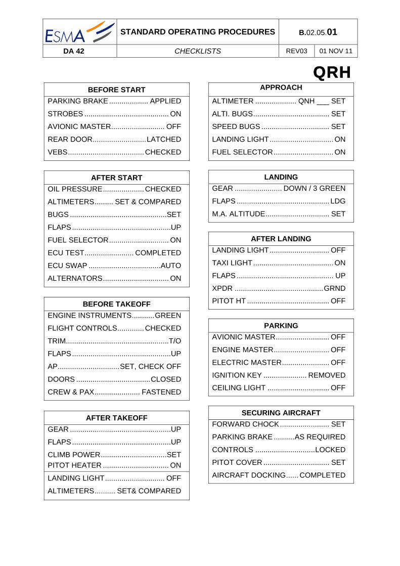
ABNORMAL AND EMERGENCY PROCEDURES B.03.06.05
DA 42 EMERGENCY CHECK LIST REV03 01 NOV 11
UNFEATHERING & RESTARTING THE
ENGINE IN FLIGHT
Restart Maximum Altitude ................................... 8000 ft
Airspeed ....................................... 110 KIAS to 120 KIAS
POWER lever affected engine ................................. IDLE
Fuel selector affected engine ................................... ON
Alternate air .................................................. As required
ENGINE MASTER ....................................................... ON
If propeller dost not start windmilling itself:
Starter affected engine ............................... Engaged
If engine power has been restored:
Alternator ................................................................. ON
In case of a failed restart:
ENGINE TROUBLES IN FLIGHT C/L
See B.03.06.03

ABNORMAL AND EMERGENCY PROCEDURES B.03.06.06
DA 42 EMERGENCY CHECK LIST REV03 01 NOV 11
ENGINE FAILURE DURING TAKE-OFF
Engine failure during ground roll
Power lever ...................................................... Both IDLE
Rudder ................................ Maintain directional control
Brakes ............................................................ As required
If runway vacated:
ENGINE MASTER ............................................. Both OFF
FUEL SELECTOR ............................................. Both OFF
ELECT. MASTER ............................... ATC advised / OFF
Engine failure after lift-off
If landing gear is still extended and the remaining runway/surface is adequate:
Abort the take-off and land straight ahead, turning to avoid obstacle.
If the remaining runway/surface is inadequate:
Decide whether to abort or to continue the take-off.
CONTINUED

ABNORMAL AND EMERGENCY PROCEDURES B.03.06.07
DA 42 EMERGENCY CHECK LIST REV03 01 NOV 11
ENGINE FAILURE DURING TAKE-OFF
CONTINUED TAKE-OFF
Power lever ............................................................... MAX
Rudder .................................................................. control
Landing gear ............................................................... UP
FLAPS .......................................................................... UP
Airspeed .................................................................... VYSE
INOPERATIVE ENGINE
Inoperative engine N°X .................. Identified & Verified
ENGINE MASTER N°X ............................................... OFF
Alternator N°X ............................................................ OFF
FUEL SELECTOR N°X ............................................... OFF
Continue according:
FLIGHT WITH ONE ENGINE INOPERATIVE C/L
See B.03.06.11
Land as soon as possible according to:
LANDING WITH ONE ENGINE INOPERATIVE C/L
See B.03.06.09
If the situation allows, you may climb to a safe altitude in order to try restore engine power:
ENGINE TROUBLES IN FLIGHT C/L
See B.03.06.03

ABNORMAL AND EMERGENCY PROCEDURES B.03.06.08
DA 42 EMERGENCY CHECK LIST REV03 01 NOV 11
ENGINE FAILURE IN FLIGHT
Rudder ................................................................. Control
Airspeed ................................................... VYSE minimum
OPERATIVE ENGINE
Operative engine ................Increase power as required
Landing Gear ............................................................... UP
Flaps ............................................................................ UP
INOPERATIVE ENGINE
Inoperative engine N°X .................. Identified & Verified
ENGINE MASTER N°X ............................................... OFF
Alternator N°X ........................................................... OFF
FUEL SELECTOR N°X ............................................... OFF
Continue according:
FLIGHT WITH ONE ENGINE INOPERATIVE C/L
See B.03.06.11
Land as soon as possible according to:
LANDING WITH ONE ENGINE INOPERATIVE C/L
See B.03.06.09
If the situation allows, you may climb to a safe altitude in order to try restore engine power:
ENGINE TROUBLES IN FLIGHT C/L
See B.03.06.03

ABNORMAL AND EMERGENCY PROCEDURES B.03.06.09
DA 42 EMERGENCY CHECK LIST REV03 01 NOV 11
LANDING WITH ONE ENGINE
INOPERATIVE
OPERATIVE ENGINE
FUEL SELECTOR .......... ON / CROSSFEED as required
INOPERATIVE ENGINE
Inoperative engine ............................................. Secured
FLAPS ............................................................................. As required
Landing gear ........................ DOWN / 3 GREEN (on the glide path)
Final approach speed ................................. 90 Kts IAS (FLAPS UP)
................................................................. 85 Kts IAS (FLAPS APP)

ABNORMAL AND EMERGENCY PROCEDURES B.03.06.10
DA 42 EMERGENCY CHECK LIST REV03 01 NOV 11
GO AROUND WITH ONE ENGINE
INOPERATIVE
If flaps LDG
Flaps ......................................................................... APP
Power lever ............................................................... MAX
Rudder ............................... Maintain directional control
Landing gear ............................................................... UP
FLAPS .......................................................................... UP
Airspeed .................................................................... VYSE
If a positive rate of climb cannot be established:
Land so as to keep clear of obstacles with the landing gear extended.
If time allows the following steps can reduce the risk of fire in an event of collision with obstacles after touchdown:
Engine master .......................................................... OFF
Fuel selector ............................................................. OFF
Electric master .......................................................... OFF

ABNORMAL AND EMERGENCY PROCEDURES B.03.06.11
DA 42 EMERGENCY CHECK LIST REV03 01 NOV 11
FLIGHT WITH ONE ENGINE INOPERATIVE
Airspeed ....................................................... Above VMCA
Remaining engine instruments .................... Monitored
Fuel quantity .................................................. Monitored
Fuel selector ...................................... CROSSFEED / ON
Set CROSSFEED or ON so as to keep fuel quantity laterally balanced
Land as soon as possible according to :
LANDING WITH ONE ENGINE INOPERATIVE C/L
See B.03.06.09
If the situation allows, you may climb to a safe altitude in order to try restore engine power:
ENGINE TROUBLES IN FLIGHT C/L
See B.03.06.08

ABNORMAL AND EMERGENCY PROCEDURES B.03.06.12
DA 42 EMERGENCY CHECK LIST REV03 01 NOV 11
LANDING GEAR UNSAFE WARNING
If the light remains on for longer than 20 seconds during landing gear retraction/extension:
Airspeed ............................................. Check below VLOR
Gear selector ..................................................... Re-cycle
..................................... if continued illumination occurs
If the landing gear cannot be extended to the down & locked position or red light does not extinguished, continue with:
MANUAL EXTENSION OF THE LANDING GEAR C/L
See B.03.06.13
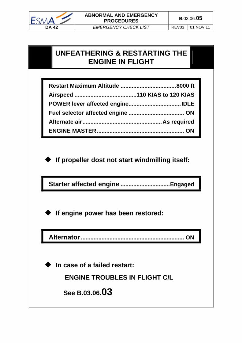
ABNORMAL AND EMERGENCY PROCEDURES B.03.06.13
DA 42 EMERGENCY CHECK LIST REV03 01 NOV 11
MANUAL EXTENSION OF THE
LANDING GEAR
The following checks shall be completed before extending the landing gear manually:
Gear indicator lights ............................................ Tested
ELECT. MASTER ........................................ Checked ON
Bus voltage ............................... Checked normal range
Circuit breaker ........... Checked IN / Reset if necessary
Manual landing gear extension procedure:
Airspeed ......................................... Checked below Vlor
Gear selector ............................................. Select DOWN
Manual gear extension ................................ Pulled OUT
Gear indicator .................................. Checked 3 GREEN
If the landing gear cannot be extended to the down & locked position continue according to:
LANDING WITH GEAR UP C/L
See B.03.06.14

ABNORMAL AND EMERGENCY PROCEDURES B.03.06.14
DA 42 EMERGENCY CHECK LIST REV03 01 NOV 11
LANDING WITH GEAR UP
Apply this procedure only if the landing gear is completely retracted.
Approach at normal approach airspeed & flaps setting
Power lever ........................ IDLE just before touchdown
Gear indicator lights ........................... Checked Gear UP
If time / situation allow the following steps can reduce the risk of fire:
ENGINE MASTER ............................................. Both OFF
Fuel selector ..................................................... Both OFF
ELECT. MASTER ........................................................ OFF
Touchdown:
Touchdown .......... Contact surface with min. airspeed
On ground .......................... Maintain control with rudder ............................................................ as long as possible

ABNORMAL AND EMERGENCY PROCEDURES B.03.06.15
DA 42 EMERGENCY CHECK LIST REV03 01 NOV 11
LANDING WITH DEFECTIVE TIRE
Advise ATC
Land the airplane at the edge of the runway that is located on the side of the intact tire.
Land with the wing on the side of the intact tire low.
Direction maintained using the rudder.
LANDING WITH DEFECTIVE BRAKES
If sufficient time is remaining, after touch down:
ENGINE MASTER ........................................... Both OFF
FUEL SELECTOR ........................................... Both OFF
ELECT. MASTER ...................................................... OFF

ABNORMAL AND EMERGENCY PROCEDURES B.03.06.16
DA 42 EMERGENCY CHECK LIST REV03 01 NOV 11
COMPLETE ELECTRICAL FAILURE
Circuit breakers ......................... Check if all pressed in
If there is still no power available:
EMERGENCY SWITCH ........................... ON, if installed
Flood light, if necessary ........................................... ON
Power ........................................................ Set based on
.................................................................. lever position
............................................................ and engine noise
Prepare landing with flaps in the given position:
FLAPS FAILURE ABNORMAL C/L
See B.03.04.05 Prepare manual gear extension :
MANUAL EXTENSION OF THE LANDING GEAR
See B.03.06.13
Land on the nearest suitable airfield
HIGH CURRENT
Circuit breaker ........................... Check if all pressed in
Reduce electric load to minimum required for continued safe flight.
Land on the nearest suitable airfield.

ABNORMAL AND EMERGENCY PROCEDURES B.03.06.17
DA 42 EMERGENCY CHECK LIST REV03 01 NOV 11
STARTER MALFUNCTION
Power lever on affected engine ............................... IDLE
ENGINE MASTER on affected engine ...................... OFF
ELECT. MASTER ........................................................ OFF
Terminate flight preparation
ENGINE FIRE ON GROUND
ENGINE MASTER ....................................................... OFF
FUEL SELECTOR ....................................................... OFF
ELECTRIC. MASTER .................................................. OFF
After standstill:
Canopy ..................................................................... OPEN
Airplane ........................................ Evacuate immediately

ABNORMAL AND EMERGENCY PROCEDURES B.03.06.18
DA 42 EMERGENCY CHECK LIST REV03 01 NOV 11
ENGINE FIRE DURING TAKE-OFF
Engine failure during ground roll
Cabin heat & Defrost ................................................. OFF
Power lever ...................................................... Both IDLE
Rudder ................................ Maintain directional control
Brakes ............................................................ As required
ENGINE MASTER ............................................. Both OFF
FUEL SELECTOR ............................................. Both OFF
ELECT. MASTER ............................... ATC advised / OFF
Engine failure after lift-off
Cabin heat & Defrost ................................................. OFF
If landing gear is still extended and the remaining runway/surface is adequate:
Abort the take-off and land straight ahead, turning to avoid obstacle.
If the remaining runway/surface is inadequate:
Decide whether to abort or to continue the take-off.
CONTINUED

ABNORMAL AND EMERGENCY PROCEDURES B.03.06.19
DA 42 EMERGENCY CHECK LIST REV03 01 NOV 11
ENGINE FIRE DURING TAKE-OFF
CONTINUED TAKE-OFF
Power lever ............................................................... MAX
Rudder ................................................................. Control
Landing gear ............................................................... UP
FLAPS .......................................................................... UP
Airspeed .................................................................... VYSE
INOPERATIVE ENGINE
Inoperative engine N°X .................. Identified & Verified
ENGINE MASTER N°X .............................................. OFF
FUEL SELECTOR N°X .............................................. OFF
Alternator N°X ............................................................ OFF
Continue according:
FLIGHT WITH ONE ENGINE INOPERATIVE C/L
See B.03.06.11
Land as soon as possible according to:
LANDING WITH ONE ENGINE INOPERATIVE C/L
See B.03.06.09
If the situation allows, you may climb to a safe altitude in order to try restore engine power:
ENGINE TROUBLES IN FLIGHT C/L
See B.03.06.03

ABNORMAL AND EMERGENCY PROCEDURES B.03.06.20
DA 42 EMERGENCY CHECK LIST REV03 01 NOV 11
ENGINE FIRE IN FLIGHT
Cabin heat & Defrost ................................................ OFF
Rudder ............................... Maintain directional control
Airspeed ................................ As required / Above VMCA
OPERATIVE ENGINE
Operative engine ...............Increase power as required
INOPERATIVE ENGINE
Inoperative engine N°X ................. Identified & Verified
ENGINE MASTER N°X .............................................. OFF
FUEL SELECTOR N°X .............................................. OFF
Alternator N°X .......................................................... OFF
Continue according:
FLIGHT WITH ONE ENGINE INOPERATIVE C/L
See B.03.06.11
Land as soon as possible according to:
LANDING WITH ONE ENGINE INOPERATIVE C/L
See B.03.06.09
If the situation allows, you may climb to a safe altitude in order to try restore engine power:
ENGINE TROUBLES IN FLIGHT C/L
See B.03.06.03

ABNORMAL AND EMERGENCY PROCEDURES B.03.06.21
DA 42 EMERGENCY CHECK LIST REV03 01 NOV 11
ELECTRICAL FIRE ON THE GROUND
ELECT. MASTER ...................................................... OFF
If the engine is running:
Power lever ..................................................... Both IDLE
ENGINE MASTER ............................................ Both OFF
FUEL SELECTOR ............................................ Both OFF
When engine has stopped:
Canopy ................................................................... OPEN
Airplane ...................................... Evacuate immediately
ELECTRICAL FIRE IN FLIGHT
EMERGENCY SWITCH ............................ ON, if installed
AVIONIC MASTER ...................................................... OFF
ELECT. MASTER ........................................................ OFF
Cabin heat & Defrost ................................................. OFF
Emergency windows ........................... OPEN if required
Land at the next suitable airfield

ABNORMAL AND EMERGENCY PROCEDURES B.03.06.22
DA 42 EMERGENCY CHECK LIST REV03 01 NOV 11
SUSPICION OF CARBON MONOXIDE
Cabin heat & Defrost ................................................. OFF
Ventilation ................................................................ OPEN
Emergency windows .............................................. OPEN
Airspeed ........................................................ 120 kts MAX
Forward canopy ........................................ Partially open
UNLOCKED DOORS
Airspeed ................................................................ Reduce
Canopy ...................................... Check visually if closed
Rear passenger door ............... Check visually if closed
Front baggage door ................. Check visually if closed
If it is not possible to lock the canopy or the rear passenger door, or if one or both of the front doors are open, land at the nearest suitable airfield.
ABNORMAL AND EMERGENCY PROCEDURES B.03.06.23
DA 42 EMERGENCY CHECK LIST REV03 01 NOV 11
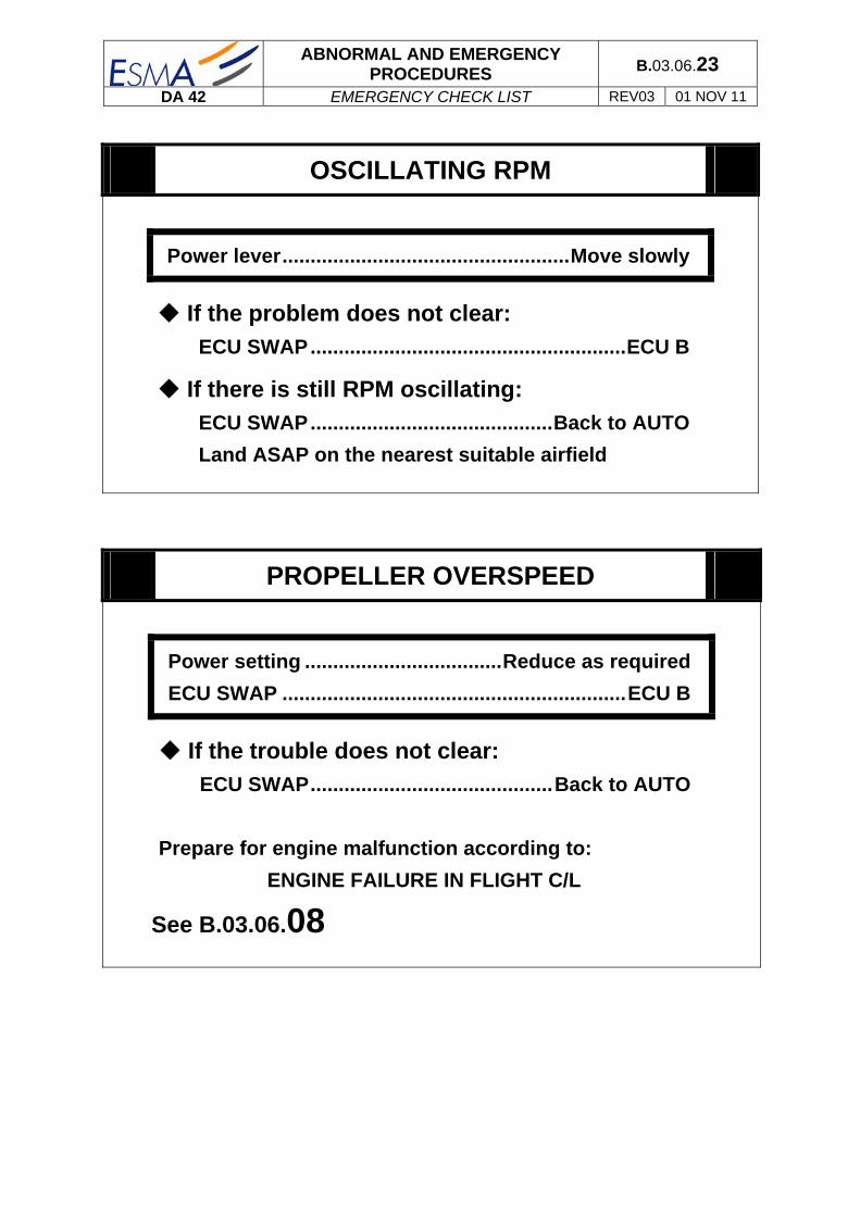
OSCILLATING RPM
Power lever ................................................... Move slowly
If the problem does not clear:
ECU SWAP ........................................................ ECU B
If there is still RPM oscillating:
ECU SWAP ........................................... Back to AUTO
Land ASAP on the nearest suitable airfield
PROPELLER OVERSPEED
Power setting ................................... Reduce as required
ECU SWAP ............................................................. ECU B
If the trouble does not clear:
ECU SWAP ........................................... Back to AUTO
Prepare for engine malfunction according to:
ENGINE FAILURE IN FLIGHT C/L
See B.03.06.08

ABNORMAL AND EMERGENCY PROCEDURES B.03.06.24
DA 42 EMERGENCY CHECK LIST REV03 01 NOV 11
FUEL SUPPLY FAILURE
FUEL SELECTOR on affected engine ...... CROSSFEED
Fuel quantity .................................................... Monitored
RECOVERY FROM A SPIN
Immediately and simultaneously:
Power lever .......................................................... IDLE
Rudder ....... Full deflection against direction of spin
Elevator ................................................... Fully foward
Ailerons ........................................................... Neutral
Flaps ........................................................................ UP
When rotation has stopped:
Rudder ............................................................. Neutral
Elevator ................................................. Pull carefully
Return the airplane from a descending into a normal flight attitude. Do not exceed the VNE

ABNORMAL AND EMERGENCY PROCEDURES B.03.06.25
DA 42 EMERGENCY CHECK LIST REV03 01 NOV 11
EMERGENCY DESCENT
FLAPS ........................................................................... UP
Gear ......................................................................... DOWN
Power lever ................................................................ IDLE
Airspeed ........................................................ As required
G1000 SYSTEM WARNING: RED X
A red X through any display field, such as COM frequencies, NAV frequencies, or engine data, indicates that display field is not receiving valid data.
G1000 SYSTEM WARNING: POSN ERROR
The system will flag and no longer provide GPS based navigational guidance.

ABNORMAL AND EMERGENCY PROCEDURES B.03.06.26
DA 42 EMERGENCY CHECK LIST REV03 01 NOV 11
G1000 SYSTEM WARNING: ATTITUDE FAIL
The display system is not receiving attitude reference information from the AHRS; accompanied by the removal of sky/ground presentation and a red X over the attitude area.
Revert to the standby by attitude indicator.
G1000 SYSTEM WARNING: AIRSPEED
FAIL
The display system is not receiving airspeed input from the air data computer; accompanied by a red X through the airspeed display.
G1000 SYSTEM WARNING: ALTITUDE FAIL
The display system is not receiving altitude input from the air data computer; accompanied by a red X through the altimeter display.
Revert to the standing altimeter.

ABNORMAL AND EMERGENCY PROCEDURES B.03.06.27
DA 42 EMERGENCY CHECK LIST REV03 01 NOV 11
G1000 SYSTEM WARNING: VERT SPEED
FAIL
The display system is not receiving vertical speed input from the air data computer; accompanied by a red X through the vertical speed display.
Determine vertical speed based on the change of altitude information.
G1000 SYSTEM WARNING: HDG
The display system is not receiving valid heading input from the AHRS; accompanied by a red X through the digital heading display.
Revert to the emergency compass.
G1000 SYSTEM WARNING: WARN
Ram position warning – nav deviation bar removed
CDI softkey .................................................. switch to VOR/LOC

ABNORMAL AND EMERGENCY PROCEDURES B.03.06.28
DA 42 EMERGENCY CHECK LIST REV03 01 NOV 11
NAVIGATION INFORMATION FAILURE
If G1000 GPS navigation is not available or invalid, utilise remaining operational navigation equipment as required.
PFD OR MFD DISPLAY FAILURE
DISPLAY BACK UP BUTTON ..................................... ON
AHRS FAILURE
NOTE
A Failure Of The Attitude And Heading Reference System (AHRS) Is Indicated By A Removal Of The sky/ground presentation and a red X and a yellow “AHRS FAILURE” shown on the PFD. The digital heading presentation will be replaced with a yellow “DHG” and the compass rose digits will be removed. The course pointer will indicate straight up and course may be set using the digital window.
Use standby attitude indicator, emergency compass and Navigation map
Course ................................ Set using digital window

ABNORMAL AND EMERGENCY PROCEDURES B.03.06.29
DA 42 EMERGENCY CHECK LIST REV03 01 NOV 11
AIR DATA COMPUTER (ADC) FAILURE
NOTE
Complete loss of the Air Data Computer is indicated by a red X and yellow text over the airspeed, altimeter, vertical speed, TAS and OAT displays. Some FMS functions, such as true airspeed and wind calculations, will also be lost.
Use standby airspeed indicator and altimeter.
ERRONEOUS OR LOSS OF
WARNING/CAUTION ANNUNCIATORS
NOTE
Loss of an annunciator may be indicated when engine or fuel displays show an abnormal or emergency situation and the annunciator is not present. An erroneous annunciator may be identified when an annunciator appears which does not agree with other displays or system information
if an annunciator appears, treat it as if the condition exists. Refer chapter EMERGENCY PROCEDURES or chapter ABNORMAL OPERATING PROCEDURES.
If a display indicates an abnormal condition but no annunciator is present, use other system information, such as engine displays, GPS fuel quantity and flow, to determine if the condition exists. If it cannot be determined that the condition does not exist, treat the situation as if the condition exists. Refer chapter EMERGENCY PROCEDURES or chapter ABNORMAL OPERATING PROCEDURES.

ABNORMAL AND EMERGENCY PROCEDURES B.03.06.30
DA 42 EMERGENCY CHECK LIST REV03 01 NOV 11
INTENTIONALLY LEFT BLANK

ABNORMAL AND EMERGENCY PROCEDURES B.03.04.01
DA 42 ABNORMAL CHECK LIST REV03 01 NOV 11
TAKE OFF FROM A LIMITATIVE RUNWAY ............................ B.03.04.03
PRECAUTIONARY LANDING ................................................... B.03.04.04
LANDING WITH HIGH LANDING MASS .................................. B.03.04.05
FLAPS FAILURE ....................................................................... B.03.04.05
CANOPY IN COOLING GAP POSITION ................................... B.03.04.06
FLAPS UP LANDING ................................................................ B.03.04.06
ALTERNATE STATIC SOURCE ............................................... B.03.04.07
START-UP USING A GPU ........................................................ B.03.04.07
BATTERY CHARGE CHECK .................................................... B.03.04.08
ENGINE INDICATING OUTSIDE GREEN RANGE 0
HIGH RPM .......................................................................... B.03.04.08
COOLANT TEMPERATURE ............................................... B.03.04.09
OIL TEMPERATURE .......................................................... B.03.04.10
OIL PRESSURE.................................................................. B.03.04.11
GEARBOX TEMPERATURE .............................................. B.03.04.11 FUEL TEMPERATURE ....................................................... B.03.04.12 VOLTAGE ........................................................................... B.03.04.12
CAUTION-ALERTS ON THE G10000
L/R ECU A FAIL .................................................................. B.03.04.13
L/R ECU B FAIL .................................................................. B.03.04.14
L/R FUEL LOW ................................................................... B.03.04.15
L/R XFER FAIL ................................................................... B.03.04.15
LOW VOLTAGE (LOW VOLTS) .......................................... B.03.04.16
L/R ALTN FAIL .................................................................... B.03.04.17
L/R COOL LVL .................................................................... B.03.04.18
PITOT FAIL / HT OFF ......................................................... B.03.04.19
STALL HT FAIL / OFF ......................................................... B.03.04.19
STICK LIMIT ....................................................................... B.03.04.20
RAIM UNAVAIL ................................................................... B.03.04.21

ABNORMAL AND EMERGENCY PROCEDURES B.03.04.02
DA 42 ABNORMAL CHECK LIST REV03 01 NOV 11
AHRS ALIGNING ................................................................ B.03.04.21
FAILURE IN HYDRAULIC SYSTEM ................................... B.03.04.22 L/R FUEL TRANSFER FAIL ............................................... B.03.04.23 L/R AUXILIARY FUEL TANK EMPTY ................................. B.03.04.23 FAILURES IN FLAP OPERATING SYSTEM ...................... B.03.04.24
LIGHTNING STRIKE ................................................................. B.03.04.25
AP FAILURE .............................................................................. B.03.04.26

ABNORMAL AND EMERGENCY PROCEDURES B.03.04.03
DA 42 ABNORMAL CHECK LIST REV03 01 NOV 11
TAKE OFF FROM A LIMITATIVE RUNWAY
Brakes ................................................................................... Applied
Flaps ............................................................................................. UP
Power lever ................................................................................ MAX
Elevator................................................................................. Fully aft
Brakes ................................................................................. Released
Hold centre line .......................................................... Using Rudder
Elevator (control stick) ............................................ Release slowly
Airspeed .................................................................. 70 kts (1700 kg)
.................................................................................. 72 kts (1785 kg)
Flaps ............................................................................................. UP
ABOVE TAKE OFF SAFE ALTITUDE:
Airspeed .................................................................. 77 kts (1700 kg)
.................................................................................. 79 kts (1785 kg)
AFTER T/O procedure and check list ........................... Performed

ABNORMAL AND EMERGENCY PROCEDURES B.03.04.04
DA 42 ABNORMAL CHECK LIST REV03 01 NOV 11
PRECAUTIONARY LANDING
Appropriate landing area .................................................... Chosen
Wind ............................................................................... Considered
Approach ......................................................................... Performed
Airspeed ................................................................................ ≥95 kts
ATC ...................................................................................... Advised
ON FINAL APPROACH:
Flaps .......................................................................................... LDG
Airspeed ........................................................ 76 kts (up to 1700kg)
....................................................................... 78 kts (above 1700kg)
Safety harnesses ................................................................. Tighten
Touchdown with the lowest possible airspeed
AFTER A SAFE TOUCHDOWN:
Emergency fuel valve ................................................................ OFF
ENGINE MASTER ....................................................................... OFF
ELECTRIC MASTER ................................................................... OFF

ABNORMAL AND EMERGENCY PROCEDURES B.03.04.05
DA 42 ABNORMAL CHECK LIST REV03 01 NOV 11
LANDING WITH HIGH LANDING MASS
Final approach speed ........................................................... 100 kts
FLAPS FAILURE
Actual Flaps position .......................................... Visually checked
Flaps selector ............................................................ In accordance
FLAPS breaker ........................................................................ Set in
THE BREAKER REMAINS IN POSITION:
Flaps selector ........................................................................ Tested
The pilot tests by changing the Flaps configuration in respect with air speed limitations as VFE and Vs.
THE BREAKER DOESN’T REMAIN IN POSITION, OR THERE IS NO CHANGE IN THE SITUATION:
FLAPS circuit-breaker .......................................................... Set out
THE FLAP SETTING AVAILABLE IS LDG:
IAS ............................................................................... VFE ldg MAX.
Perform a normal landing
THE FLAP SETTING AVAILABLE IS APP:
IAS .............................................................................. VFE app MAX.
FLAPS UP LANDING Check-list .................................... Performed
See 03.04.06
THE FLAP SETTING AVAILABLE IS UP:
FLAPS UP LANDING Check-list .................................... Performed
See 03.04.06

ABNORMAL AND EMERGENCY PROCEDURES B.03.04.06
DA 42 ABNORMAL CHECK LIST REV03 01 NOV 11
CANOPY IN COOLING GAP POSITION
If take-off was inadvertently done with the canopy in the cooling gap position, do not attempt to close the canopy in flight. Land the aircraft and close the canopy on ground.
FLAPS UP LANDING
Landing distance available ........................ Sufficient or diversion
Landing without flap increases the landing distance by 60 % for the DA 42
Approach speed .................................................................... 100 kts
Final speed ................................................... 90 kt + WIND EFFECT
ON RUNWAY
Maximum brake if necessary
100 ft Decision
300 ft Stabilization
= +1° IAS = 90 kts Load = 20% Vz = 450 ft/min
LDG Procedure & Check List
IAS = 100 kts Load = 20% = +1° Vz = 400 ft/min
Abeam threshold
TOP for 1min without wind.
IAS = 100 kts = +2° Load 35% (with gear up)
Turn initiation = +3° = 15° IAS = 100 kts Load = 50% (with gear down)
Descent initiation
= 0° Load = 20%

ABNORMAL AND EMERGENCY PROCEDURES B.03.04.07
DA 42 ABNORMAL CHECK LIST REV03 01 NOV 11
ALTERNATE STATIC SOURCE
Alternate Static ....................................................................... OPEN
Emergency window .............................................................. Closed
Cockpit Vents ........................................................................ Closed
START-UP USING A GPU
GPU Voltage ................................................................ 25 to 28 VDC
Avionic Master Switch ............................................................... OFF
Electric Master Switch ............................................................... OFF
Proceed with the GPU connection followed by engine start procedure according to normal procedures adding the following items:
BEFORE STARTING THE ENGINE:
External safety ................................................................... Checked
Advise ground staff of the forthcoming start up.
AFTER STARTING THE ENGINE:
Throttle ...................................................................................... IDLE
GPU ............................................................................ Disconnected

ABNORMAL AND EMERGENCY PROCEDURES B.03.04.08
DA 42 ABNORMAL CHECK LIST REV03 01 NOV 11
BATTERY CHARGE CHECK
Engine .................................................................................... Started
GPU ............................................................................ Disconnected
Taxi and Landing lights ............................................................... ON
Power lever ....................................................................... 1500 RPM
Voltmeter ............................................................................ Checked
If the voltmeter shows a reading within the red range, shut down the engine and have the battery re-charged.
Taxi and Landing lights ............................................................. OFF
HIGH RPM
Power .................................................................................... Reduce
Keep RPM within the green range using the power lever

ABNORMAL AND EMERGENCY PROCEDURES B.03.04.09
DA 42 ABNORMAL CHECK LIST REV03 01 NOV 11
COOLANT TEMPERATURE (CT)
HIGH CT
L/R COOL LVL caution message ...................................... Checked
IF L/R COOL LVL CAUTION MESSAGE IS NOT DISPLAYED:
DURING CLIMB:
Power on affected engine ......................... Reduce by 10%
Airspeed ................................................. Increase by 10 kts
If the coolant temperature does not reach the green range within 60 seconds, reduce power as far as possible and increase airspeed.
DURING CRUISE:
Power on affected engine ...................................... Reduce
Airspeed ................................................................. Increase
CT in green range ................................................. Checked
IF L/R COOL LVL CAUTION MESSAGE IS DISPLAYED:
Power on affected engine ...................................... Reduce
Expect loss of coolant.
LOW CT
L/R COOL LVL caution message ...................................... Checked
IF WATER LEVEL CAUTION LIGHT IS ON:
DURING CLIMB:
Power lever .............................................................. Reduce
Expect loss of coolant.

ABNORMAL AND EMERGENCY PROCEDURES B.03.04.10
DA 42 ABNORMAL CHECK LIST REV03 01 NOV 11
OIL TEMPERATURE (OT)
HIGH OT
OP (Oil Pressure) ............................................................... Checked
IF OP IS LOW:
Power on affected engine ................................................... Reduce
Expect loss of oil with engine failure
IF OP IS WITHIN THE GREEN RANGE:
Power on affected engine ................................................... Reduce
Airspeed ............................................................................. Increase
LOW OT
Power on affected engine ................................................. Increase
Airspeed ............................................................................... Reduce

ABNORMAL AND EMERGENCY PROCEDURES B.03.04.11
DA 42 ABNORMAL CHECK LIST REV03 01 NOV 11
OIL PRESSURE (OP)
HIGH OP
OT (Oil Temperature) ......................................................... Checked
CT (Coolant Temperature) ................................................ Checked
IF TEMPERATURES ARE WITHIN THE GREEN RANGE:
Expect wrong oil pressure indication
Keep monitoring temperatures
IF TEMPERATURES ARE NOT WITHIN THE GREEN RANGE:
Power affected engine .................................................... Reduce
Expect Engine failure
LOW OP
Power on affected engine ................................................... Reduce
Expect loss of oil with engine failure
GEARBOX TEMPERATURE (GT)
HIGH GT
Power on affected engine ................................................... Reduce
Airspeed ............................................................................. Increase

ABNORMAL AND EMERGENCY PROCEDURES B.03.04.12
DA 42 ABNORMAL CHECK LIST REV03 01 NOV 11
FUEL TEMP
HIGH FUEL TEMP
Power on affected engine ................................................... Reduce
Airspeed ............................................................................. Increase
LOW FUEL TEMP
Power on affected engine ................................................. Increase
Airspeed ............................................................................... Reduce
VOLTAGE
ON THE GROUND
Circuit breakers ................................................................. Checked
Power lever ................................................................ Increase RPM
If low voltage caution is still indicated on the G1000: Terminate flight preparation
DURING FLIGHT
Circuit breakers ................................................................. Checked
Electrical equipment .......................................... OFF if not needed
If LOW VOLTAGE CAUTION is still indicated on the G1000: follow procedure L/R ALTN FAIL
See B.03.04.17
DURING LANDING
Follow the “ON THE GROUND” check list above after landing

ABNORMAL AND EMERGENCY PROCEDURES B.03.04.13
DA 42 ABNORMAL CHECK LIST REV03 01 NOV 11
L/R ECU A FAIL
ON THE GROUND
Terminate flight preparation
DURING FLIGHT
In case of a failure in the electronic ECU “A”, the system automatically switches to ECU “B”.
Press the ECU TEST button for more than 2 seconds to reset the caution message.
If the ECU A caution message re-appears, or cannot be reset:
Land on the nearest suitable airfield.
The engine must be serviced after landing.
If the ECU A caution message can be reset:
Continue flight.
The engine must be serviced after landing.

ABNORMAL AND EMERGENCY PROCEDURES B.03.04.14
DA 42 ABNORMAL CHECK LIST REV03 01 NOV 11
L/R ECU B FAIL
ON THE GROUND
Terminate flight preparation
DURING FLIGHT
Press the ECU TEST button for more than 2 seconds to reset the caution message.
If the ECU B caution message re-appears, or cannot be reset:
Land on the nearest suitable airfield.
The engine must be serviced after landing.
If the ECU B caution message can be reset:
Continue flight.
The engine must be serviced after landing.

ABNORMAL AND EMERGENCY PROCEDURES B.03.04.15
DA 42 ABNORMAL CHECK LIST REV03 01 NOV 11
L/R FUEL LOW
Fuel quantity ...................................................................... Checked
If fuel quantities of LH & RH engines show remarkable different fuel quantities in flight:
Expect loss of fuel on side with lower indication
Use crossfeed function to ensure fuel supply
Fuel selector .................................................................... Crossfeed
Select crossfeed on the engine with low fuel indication
L/R XFER FAIL
Fuel quantity ...................................................................... Checked
If fuel quantities of LH & RH engines show remarkable different fuel quantities in flight:
Expect loss of fuel on side with lower indication
Use crossfeed function to ensure fuel supply
Fuel selector .................................................................... Crossfeed
Select crossfeed on the engine with low fuel indication

ABNORMAL AND EMERGENCY PROCEDURES B.03.04.16
DA 42 ABNORMAL CHECK LIST REV03 01 NOV 11
L/R VOLTS LOW
ON THE GROUND
Circuit breakers ................................................................. Checked
Power lever ................................................................ Increase RPM
If LOW VOLTAGE CAUTION is still indicated on the G1000: Terminate flight preparation
DURING FLIGHT
Circuit breakers ................................................................. Checked
Electrical equipment .......................................... OFF if not needed
If LOW VOLTAGE CAUTION is still indicated on the G1000: follow procedure L/R ALTN FAIL
See B.03.04.17
DURING LANDING
Follow the “ON THE GROUND” check list above after landing

ABNORMAL AND EMERGENCY PROCEDURES B.03.04.17
DA 42 ABNORMAL CHECK LIST REV03 01 NOV 11
L/R ALTN FAIL
ONE ALTERNATOR FAILED
Circuit breakers ................................................................. Checked
Alternator on affected engine ................................................... OFF
Bus voltage .......................................................................... Monitor
Electrical consumers ................................... reduce as practicable
Coolant Temperature ............................................................ Check
(the alternator belt acts on the coolant pump)
BOTH ALTERNATOR FAILED
WARNING
If both alternators fail at the same time, reduce all electrical equipment to a minimum. Expect battery power to last 30 minutes and land the airplane as soon as possible. Expect engine stoppage after this time.
Circuit breakers ................................................................. Checked
Avionic master ........................................................................... OFF
LH/RH Alternator ........................................................................ OFF
XPDR ........................................................................................ STBY
Landing gear ........................................................................... Down
when down and locked, pull emergency release
Stall / Pitot heat .......................................................................... OFF
All lights ...................................................................................... OFF

ABNORMAL AND EMERGENCY PROCEDURES B.03.04.18
DA 42 ABNORMAL CHECK LIST REV03 01 NOV 11
L/R COOL LVL
HIGH CT
L/R COOL LVL caution message ...................................... Checked
IF L/R COOL LVL CAUTION MESSAGE IS NOT DISPLAYED:
DURING CLIMB:
Power on affected engine ......................... Reduce by 10%
Airspeed ................................................. Increase by 10 kts
If the coolant temperature does not reach the green range within 60 seconds, reduce power as far as possible and increase airspeed.
DURING CRUISE:
Power on affected engine ...................................... Reduce
Airspeed ................................................................. Increase
CT in green range ................................................. Checked
IF L/R COOL LVL CAUTION MESSAGE IS DISPLAYED:
Power on affected engine ...................................... Reduce
Expect loss of coolant.
LOW CT
L/R COOL LVL caution message ...................................... Checked
IF WATER LEVEL CAUTION LIGHT IS ON:
DURING CLIMB:
Power lever .............................................................. Reduce
Expect loss of coolant.

ABNORMAL AND EMERGENCY PROCEDURES B.03.04.19
DA 42 ABNORMAL CHECK LIST REV03 01 NOV 11
PITOT FAIL / HT OFF
Pitot heater .............................................. Checked ON / As required
IF ICING CONDITION:
Expect loss of static instruments.
Open Alternate Static:
See Section B.03.04.07 - ALTERNATE STATIC SOURCE C/L
Leave icing zone
STALL HT FAIL / OFF
Pitot heater .............................................. Checked ON / As required
IF ICING CONDITION:
Expect loss of acoustic warning.
Leave icing zone

ABNORMAL AND EMERGENCY PROCEDURES B.03.04.20
DA 42 ABNORMAL CHECK LIST REV03 01 NOV 11
STICK LIMIT
AT LEAST ONE POWER LEVER IS IN POSITION FOR POWER SETTINGS OF MORE THAN 25% LOAD
The variable elevator backstop is inoperative. In case of stalling with “power-on” the handling qualities and stall characteristic are degraded significantly.
!! DO NOT STALL THE AIRPLANE IN ANY CONFIGURATION !!
AT LEAST ONE POWER LEVER IS IN POSITION FOR POWER SETTINGS OF MORE THAN 25% LOAD
The variable elevator backstop is active all the time, reducing the maximum elevator “pull”-deflection. This results in reduced elevator capacity. In this case it is important to maintain the required minimum VREF 76 KIAS during the approach for landing especially at loading conditions with forward locations of the center of gravity.
ABNORMAL AND EMERGENCY PROCEDURES B.03.04.21
DA 42 ABNORMAL CHECK LIST REV03 01 NOV 11
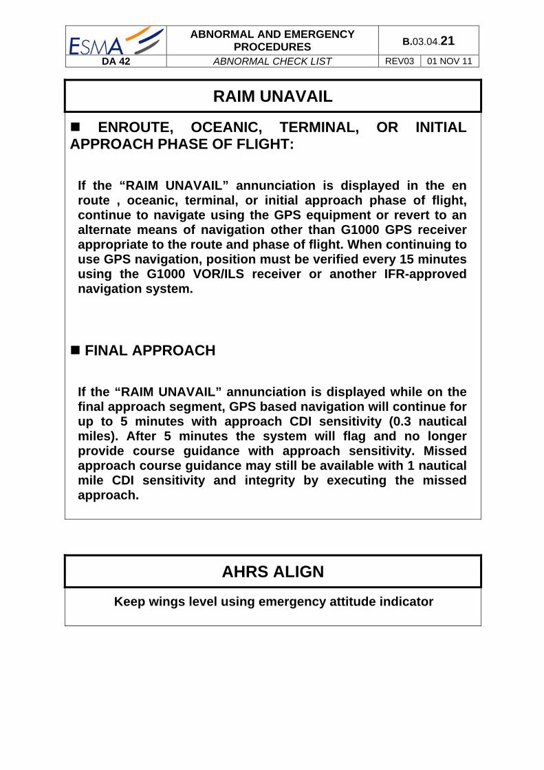
RAIM UNAVAIL
ENROUTE, OCEANIC, TERMINAL, OR INITIAL APPROACH PHASE OF FLIGHT:
If the “RAIM UNAVAIL” annunciation is displayed in the en route , oceanic, terminal, or initial approach phase of flight, continue to navigate using the GPS equipment or revert to an alternate means of navigation other than G1000 GPS receiver appropriate to the route and phase of flight. When continuing to use GPS navigation, position must be verified every 15 minutes using the G1000 VOR/ILS receiver or another IFR-approved navigation system.
FINAL APPROACH
If the “RAIM UNAVAIL” annunciation is displayed while on the final approach segment, GPS based navigation will continue for up to 5 minutes with approach CDI sensitivity (0.3 nautical miles). After 5 minutes the system will flag and no longer provide course guidance with approach sensitivity. Missed approach course guidance may still be available with 1 nautical mile CDI sensitivity and integrity by executing the missed approach.
AHRS ALIGN
Keep wings level using emergency attitude indicator

ABNORMAL AND EMERGENCY PROCEDURES B.03.04.22
DA 42 ABNORMAL CHECK LIST REV03 01 NOV 11
FAILURE IN HYDRAULIC SYSTEM
CONTINUOUS HYDRAULIC PUMP OPERATION
Landing gear indication lights .......................................... Checked
Prepare for manual landing gear extension.
Refer to Section B.03.06.13 - MANUAL EXTENSION OF THE LANDING GEAR.
The landing gear might extend as the hydraulic system pressure decreases. Consider for higher aerodynamic drag, resulting in degraded flight performance, increased fuel consumption and decreased range.
Unscheduled maintenance action is required after landing
HYDRAULIC PUMP FAILURE
Landing gear indication lights .......................................... Checked
Prepare for manual landing gear extension.
Refer to Section B.03.06.13 - MANUAL EXTENSION OF THE LANDING GEAR.
The landing gear might extend as the hydraulic system pressure decreases. Consider for higher aerodynamic drag, resulting in degraded flight performance, increased fuel consumption and decreased range.
Unscheduled maintenance action is required after landing

ABNORMAL AND EMERGENCY PROCEDURES B.03.04.23
DA 42 ABNORMAL CHECK LIST REV03 01 NOV 11
L/R FUEL TRANSFER FAIL
If the fuel quantity in a main tank does not increase during fuel transfer :
Both fuel transfer pumps switch .............................................. OFF
Check fuel imbalance in the main tanks, use crossfeed function to keep the LH and RH main tank imbalance within the permissible limit of 1 US gal (3,8 lts).
Remaining fuel pump swithc ...................................................... ON
Use crossfeed function to keep the LH and RH main tank imbalance within the permissible limit of 1 US gal (3,8 lts).
L/R AUXILIARY FUEL TANK EMPTY
Left/Right auxiliary fuel tank empty (displayed only when fuel transfer pump is ON).
L/R auxiliary fuel pump ............................................................. OFF
ABNORMAL AND EMERGENCY PROCEDURES B.03.04.24
DA 42 ABNORMAL CHECK LIST REV03 01 NOV 11
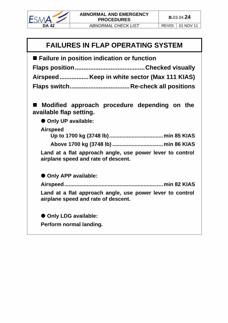
FAILURES IN FLAP OPERATING SYSTEM
Failure in position indication or function
Flaps position ......................................... Checked visually
Airspeed ................. Keep in white sector (Max 111 KIAS)
Flaps switch ................................... Re-check all positions
Modified approach procedure depending on the available flap setting.
Only UP available:
Airspeed Up to 1700 kg (3748 lb) .................................... min 85 KIAS
Above 1700 kg (3748 lb) .................................. min 86 KIAS
Land at a flat approach angle, use power lever to control airplane speed and rate of descent.
Only APP available:
Airspeed .................................................................. min 82 KIAS
Land at a flat approach angle, use power lever to control airplane speed and rate of descent.
Only LDG available:
Perform normal landing.

ABNORMAL AND EMERGENCY PROCEDURES B.03.04.25
DA 42 ABNORMAL CHECK LIST REV03 01 NOV 11
LIGHTNING STRIKE
1. Airspeed ................... as low as practicable, do not
exceed vA % (120 KIAS)
2. Grasp airplane controls firmly
3. Autopilot ............................................ disengage (check)
4. PFD / backup instruments ................. verify periodically
5. Continue flight under VMC
6. Land on next suitable airfield
CAUTION Due to possible damage to the airplane obey the following instructions:
- Avoid abrupt or full control surface movements
- Avoid high g-loads on the airframe
- Avoid high yaw angles
- Avoid turbulent air as far as possible (e.g. lee effects)
- Do not fly into areas of known or forecast icing
- Maintain VMC

ABNORMAL AND EMERGENCY PROCEDURES B.03.04.26
DA 42 ABNORMAL CHECK LIST REV03 01 NOV 11
AUTOPILOT, AUTOPILOT TRIM, OR MANUAL ELECTRIC TRIM MALFUNCTION
The four step procedure listed below should be among the basic airplane emergency procedures that are committed to memory. It is important that the pilot be proficient in accomplishing all four steps without reference to this manual.
Accomplish items 1 and 2 simultaneously!
1. Airplane control stick ............... grasp firmly and
regain airplane control
2. AP DISC switch .... press and hold throughout recovery
3. Trim ........................ retrim airplane manually as required
4. AUTOPILOT circuit breaker ..................................... pull
WARNING
Do not attempt to re-engage the autopilot following an autopilot, autotrim, or manual electric trim malfunction until the cause for the malfunction has been corrected.
NOTE
When the AUTOPILOT circuit breaker is pulled, the manual electric trim and autopilot autotrim systems will be disabled, and the AP TRIM FAIL annunciation will extinguish.

STANDARD OPERATING PROCEDURES B.02.02.01
DA 42 EXPANDED PROCEDURES REV03 01 NOV 11
EXPANDED PROCEDURES
02.01 - INTRODUCTION
Section B.02.02 contains checklists and describes procedures for the normal operation of the airplane.
NOTE
Readability of the G1000 PFD and MFD displays may be downgraded when wearing polarized sunglasses.
02.02 - PARAMETERS FOR NORMAL OPERATING PROCEDURES
Pitch KIAS Load Gear Flaps B.A.*
Airspeed for rotation (V1/VR) +5° 75 Max Down 0° ---
Normal climb +9° 90 95 Up 0° 20°
Airspeed for best rate-of-climb (VY) +11° 82/85** max Up 0° 15°
Airspeed for best angle of climb (VX) +13° 79/81** max Up 0° 10°
Cruise 60% +0° 130 60 Up 0° 37°
Cruise 70% +0° 135 70 Up 0° 37°
Descent VNO -2° 155 70 Up 0° 37°
Hold +1° 100 40 Up 0° 37
Approach level -2° 100 70 Down APP 37°
Max. structural cruising speed Do not exceed this speed except in smooth air, and then only with caution
155 KIAS KAP 140 151 KIAS GFC 700

STANDARD OPERATING PROCEDURES B.02.02.02
DA 42 EXPANDED PROCEDURES REV03 01 NOV 11
02.01 – Flight with one engine inoperative
Pitch KIAS Load Gear Flaps B.A.*
VX +6° 79/81** max Up 0° 10°
VYSE +5° 82/85** 100 Up 0° 15°
Cruise 90% (FL90) +4° 95 90 Up 0° 37°
Approach level -2° 90 70 Up APP 37°
* The B.A. is the recommended Bank Angle. ** KAP140 / GFC700
02.03 - ADVISORY ALERTS ON THE G1000
The G1000 provides the following advisory-alerts on the PFD in the alert area:
03.01 - Advisory / general
CHARACTERISTICS White color coded text
03.02 - L/R glow on
L/R GLOW ON Left / Right engine glow plug active
03.03 - L/R fuel XFER
L/R FUEL XFER Fuel transfer from auxiliary to main tank is in progress
03.03 - PFD/MFD/GIA FAN FAIL
PFD FAN FAIL Cooling fan for the PFD is inoperative MFD FAN FAIL Cooling fan for the MFD is inoperative GIA FAN FAIL Cooling fan for the GIA is inoperative The flight may be continued, but maintenance action is required after landing.

STANDARD OPERATING PROCEDURES B.02.02.03
DA 42 EXPANDED PROCEDURES REV03 01 NOV 11
02.04 - SAFETY INSPECTION
The safety inspection takes place when the aircraft is handed over to the pilot. It is meant to check:
Its general external appearance to ensure that all conditions will guarantee its safety. Inside the aircraft: to make sure that when switching on the Electric Master no damage
will be caused.
This inspection is carried out by the pilot.
DAILY CHECK
Before the first flight of a day it must be ensured that the following functions are operable without failure.
On-condition check of the canopy, the side door and the baggage compartment doors for cracks and major scratches.
On-condition check of hinges for the canopy, the side door and the baggage compartment doors.
Visual inspection of the locking bolts for proper movement with no backlash.
PREPARATION:
- General appearance ......................................................................... Checked
Prior to getting into the aircraft, the pilot checks its general condition, airframe and environment. He removes the various protective covers and pulls away the tow bar on the nose gear. As long as parking brake has not been checked, chocks on nose gear are not removed. He checks visually fuel remaining in the tanks as described in chapter 2 external inspection. He takes notice of possible remarks and comments left by previous crew or technical staff on the technical logbook. In case of any comments the pilot will have to check the compliance with the M.E.L.
- Parking brake ............................................................................................... ON
To apply parking brake:
Press on the top of both pedals ,in order to pressurize the brake system
Pull the parking brake lever downwards until it catches in order to prevent brake pressure from dropping.
- Controls ............................................................................... Released and free
- Life jackets ........................................................... On board and within reach
The pilot should check that all safety items are on board and more particularly life jackets which have to stay within reach, during flight. For front seats, the latter are to be found in the rear pockets of each seat.
CONTINUED

STANDARD OPERATING PROCEDURES B.02.02.04
DA 42 EXPANDED PROCEDURES REV03 01 NOV 11
- Foreign objects .................................................................................. Checked
- Baggage .......................................................................... Stowed and secured
ON THE INSTRUMENT PANEL:
- Gear selector .......................................................................................... DOWN
- Electric Master ........................................................................................... OFF
- Engine master ........................................................................ Check both OFF
- Start key ..................................................................... Check key is pulled out
- Circuit breakers ....................................................................................... Set in
If one has been pulled out, check reason.
CHECK PROCEDURE:
CAUTION
When switching the ELECT. MASTER ON, the electrically driven hydraulic gear pump may activate itself for 5 to 20 seconds in order to restore the system pressure. Should the pump continue to operate continuously or periodically, terminate flight. There is a malfunction in the landing gear system.
- Electric Master ............................................................................................. ON
First and foremost check that the area around the propeller is cleared. This is because the starter may be operated inadvertently if there is a problem in the electrical system.
- Gear/fire test ....................................................................................... Checked
- Flaps .................................................................................................... Set LDG
- Control stick .............................................. Pulled fully aft / held at backstop
- Power lever .......................................................................................... set MAX
- Variable elevator backstop ............................................................... Checked
Check function / backstop limit must decrease during power lever forward movement
- Power lever .......................................................................................... set IDLE
- Variable elevator backstop ............................................................... Checked
Check function / backstop limit must increase during power lever retraction
CAUTION
The proper function of the variable elevator backstop is indispensable for the safety of flight, as the handling qualities during power-on stalls are degraded significantly. For more details see section B.12.27

STANDARD OPERATING PROCEDURES B.02.02.05
DA 42 EXPANDED PROCEDURES REV03 01 NOV 11
- Position lights, strobe lights (ACL) ........................................ Checked - OFF
Switch on the lights and visually check their correct operation from cockpit.
CAUTION
Do not look directly into the anti collision lights.
- Landing / Taxi lights ................................................................ Checked - OFF
Only In the case of a night flight switch on the strobes and the position lights, and visually check their correct operation from the cockpit.
- Stall warning / stall heat / Pitot heat ................................................. Checked
- Gear warning / Fire detector TEST BUTTON ....................................... Tested
PUSH, check aural alert / Fire detection warning and aural alert
CAUTION
If aural alert or the warning on the MFD does not appear, terminate flight. Unscheduled maintenance is necessary.
- Electric master ........................................................................................... OFF
END OF SAFETY INSPECTION PROCEDURE

STANDARD OPERATING PROCEDURES B.02.02.06
DA 42 EXPANDED PROCEDURES REV03 01 NOV 11
02.05 - EXTERNAL PRE-FLIGHT INSPECTION
The external pre-flight inspection is divided in two sections. The first one is performed before walk-around check to drain off possible water from tanks and to verify oil and fuel level. If an addition in oil or fuel if necessary, its can be done at this time. Thereafter, the pilot performs the walk-around check.
05.01 - OIL, FUEL & WATER CHECK
1 - RIGHT / LEFT ENGINE NACELLE:
- Engine oil level ................................................................................... Checked
Check the oil level using the dip-stick located in the inspection hole in the upper cowling.
The oil level must be between the min/max indications on the dip-stick.
Minimum oil quantity: 4.5 liters (4.8 US qts)
Maximum oil quantity: 6.0 liters (6.3 US qts)
- Gearbox oil level ................................................................................ Checked
Check the gearbox oil level through the inspection hole on the front side of the lower cowling.
- Gascolator / air inlet ............................................................................ Drained
Drain off to check for water and sediment (drain until no water comes out).
2 - RIGHT / LEFT WING:
- Tank filler .............................................................................. Visual inspection
Use alternate mean for fuel quantity check.
- Tank drain ............................................................................................. Drained
Drain off to check for water and sediment (drain until no water comes out).

STANDARD OPERATING PROCEDURES B.02.02.07
DA 42 EXPANDED PROCEDURES REV03 01 NOV 11
05.02 - WALK-AROUND CHECK
CAUTION
A visual inspection means: examination for damage, cracks, delamination, excessive play, load transmission, correct attachment and general condition. In addition, control surfaces should be checked for freedom of movement.
CAUTION
In low ambient temperatures the airplane must be completely cleared of ice, snow and similar accumulations. For approved de-icing fluids refer to Section B.01.02.17 Ground de-incing
CAUTION
Prior flight, remove such items as control surfaces gust lock, Pitot cover, tow bar, etc.

STANDARD OPERATING PROCEDURES B.02.02.08
DA 42 EXPANDED PROCEDURES REV03 01 NOV 11
1 - FUSELAGE, LEFT SIDE, UNDERSIDE:
- Canopy, left side .................................................................. Visual inspection
- Rear cabin door & window .................................................. Visual inspection
- Fuselage skin ....................................................................... Visual inspection
- Antennas .............................................................................. Visual inspection
- Fuselage .................................................................. Check for contamination
Check that there is no hydraulic fluid on the fuselage. 2 - EMPENNAGE:
- Stabilizers and control surfaces, elevator tips ................. Visual inspection
- Hinges ................................................................................... Visual inspection
- Elevator trim tab .................................................................. Visual inspection
- Rudder trim tab .................................................................... Visual inspection
- Tie-down ................................................................................... Checked, clear
- Tail skid and lower fin ......................................................... Visual inspection
- Static dischargers ................................................................ Visual inspection 3 - FUSELAGE, RIGHT SIDE:
- Fuselage skin ....................................................................... Visual inspection
- Rear cabin door.................................................................... Visual inspection
- Canopy, right side................................................................ Visual inspection
CONTINUED

STANDARD OPERATING PROCEDURES B.02.02.09
DA 42 EXPANDED PROCEDURES REV03 01 NOV 11
4 - RIGHT WING:
- Tie-down ................................................................................... Checked, clear
- Position light, strobe light (ACL) ........................................ Visual inspection
- Static dischargers ................................................................ Visual inspection
- Wing ports ............................................................................ Visual inspection
- Openings on lower surface ............................................................... Checked
Check for foreign objects and for traces of fuel (if tank is full, fuel may be spilt over through the tank vent).
- Tank air intake on lower surface ........................................ Visual inspection
Check that there are no foreign objects inside.
- Entire wing surface .............................................................. Visual inspection
- Cabin vent air inlet .................................................................... Checked clear 5 - RIGHT MAIN LANDING GEAR:
- Landing gear strut & lock.................................................... Visual inspection
- Down & Uplock switches (3x) ............................................. Visual inspection
- Tire inflation pressure (4.5 bar / 65 PSI) ...... Checked with pressure gauge
- Wear, tread depth of fire ...................................................... Visual inspection
- Tire, wheel, brake ................................................................. Visual inspection
- Brake line connection............................................................. Check for leaks
- Slip marks ............................................................................. Visual inspection
- Chocks ............................................................................................... Removed
- Landing gear door ............................................................... Visual inspection
CONTINUED

STANDARD OPERATING PROCEDURES B.02.02.10
DA 42 EXPANDED PROCEDURES REV03 01 NOV 11
6 - RIGHT ENGINE NACELLE:
- 3 air inlets / 2 air outlets .......................................................................... Clear
- Windshield and windows ........................................................ Checked clean
- Cowling ................................................................................. Visual inspection
- Venting pipes ............................................................... Checked for blockage
- Exhaust ................................................................................. visual inspection
WARNING
The exhaust can cause burns when hot.
- Spinner including attachment screws ............................... Visual inspection
- Propeller ............................................................................... Visual inspection
Look for nicks on the propeller, particularly close to the tips and on the leading edges. If nicks are spotted refer to M.E.L. and advise maintenance department.
WARNING
Never move the propeller by hand while the ENGINE MASTER is ON! Also do not move the propeller by hand while the ENGINE MASTER is OFF immediately after operation (remaining pressure in the rail). Serious personal injury may result.
- Nacelle underside ................................................................ Visual inspection
Check for excessive contamination particularly by oil, fuel, and other fluids.
CONTINUED

STANDARD OPERATING PROCEDURES B.02.02.11
DA 42 EXPANDED PROCEDURES REV03 01 NOV 11
7 - FRONT FUSELAGE AND NOSE LANDING GEAR:
- Left and right front baggage door ...................................... Visual inspection
CAUTION
Check baggage doors are closed & locked
- Nose landing gear strut ....................................................... Visual inspection
- Down & Uplock switches .................................................... Visual inspection
- Tire inflation pressure (6 bar / 87 PSI) ......... Checked with pressure gauge
- Wear, tread depth of tire .................................................................... Checked
- Slip marks ............................................................................. Visual inspection
- Gear door and linkage ......................................................... Visual inspection
- Chocks ............................................................................................... Removed
- OAT sensor ........................................................................................ Checked
- EPU connector ................................................................................... Checked
- Tow bar .............................................................................................. Removed
8 - LEFT ENGINE NACELLE:
Checked as on right side. 9 - LEFT MAIN LANDING GEAR:
Checked as on right side. 10 - LEFT WING:
- Pitot probe ............................................................................ Visual inspection
- Stall warning device .......................................................................... Checked
Remove the cover and check that there are no foreign objects inside. - Checked as on right in inverse sequence, the cabin vent air inlet excepted.
END OF EXTERNAL PREFLIGHT INSPECTION PROCEDURE

STANDARD OPERATING PROCEDURES B.02.02.12
DA 42 EXPANDED PROCEDURES REV03 01 NOV 11
02.06 - COCKPIT PREPARATION
The cockpit preparation procedure is done for every flight.
- Mobiles ....................................................................................................... OFF
- Documents ........................................................................................ On board
Check that the statutory documents are on board and within reach.
- Rudder pedals ....................................................................... Adjusted, locked
- Pilot and PAX ..................................................................... Seatbelts fastened
- Pitch trim ..................................................................................................... T/O
- Fuel selector ................................................................................................. ON
- Fuel transfer ............................................................................................... OFF
- Power lever ................................................................................................ IDLE
- Parking brake ............................................................................................... ON
- Rudder trim ........................................................................................... Neutral
- Alternate air ................................................................................ Check closed
- Landing gear emergency extension lever ......................................... Pushed
- Alternate static valve ................................................................. Check closed
- Landing gear switch .............................................................................. DOWN
- Avionic Master ........................................................................................... OFF
- Electric Master ........................................................................................... OFF
- Engine Master ................................................................................... Both OFF
- Pitot heater ................................................................................................. OFF
CONTINUED

STANDARD OPERATING PROCEDURES B.02.02.13
DA 42 EXPANDED PROCEDURES REV03 01 NOV 11
- Alternators .................................................................................................... ON
- ECU SWAP .............................................................................................. AUTO
- All lights ...................................................................................................... OFF
The pilot checks that landing, taxi, navigation and strobe lights are on OFF position.
- Emergency battery................................................................................. Sealed
- Emergency instrument panel ............................................................ Checked
The pilot checks the coherence of the instrument indication on his instrument panel:
The airspeed indicator reading zero,
Altimeter set on the latest QNH,
ELT ............. ARM END OF COCKPIT PREPARATION PROCEDURE
02.07 - BEFORE START UP
BEFORE START UP actions are to be carried out at every flight as soon as the pilot is ready.
- Passengers ....................................................................................... Instructed
NOTE
Ensure all passengers have been fully briefed on the use of the seat belts, doors and emergency exits and the ban on smoking.
- Rear door .......................................................................... Closed and latched
- Front canopy ............................................................................. Position 1 or 2
The pilot closes the door and moves the lever to its closed position and makes sure the passenger door is equally latched.
CONTINUED

STANDARD OPERATING PROCEDURES B.02.02.14
DA 42 EXPANDED PROCEDURES REV03 01 NOV 11
- Electric master ............................................................................................. ON
CAUTION
When switching the ELECT. MASTER ON, the electrically driven hydraulic gear pump may activate itself for 5 to 20 seconds in order to restore the system pressure. Should the pump continue to operate continuously or periodically, terminate flight. There is a malfunction in the landing gear system
- Position lights .............................................................................................. ON
By switching on strobe and position lights the pilot indicates to ground staff
that the aircraft is energized.
- Strobe ........................................................................................................... ON
- Flaps ............................................................................................................. UP
- G1000 .............................................................................. ON / BACK UP Mode
Wait until power-up completed. Press ENT once (using MFD Softkeys) to check DATA BASE validity. Then press ENT again to acknowledge.
- Engine / System Page on MFD .......................................................... Selected
- Request airfield data....................................................................... Completed
ATIS can be copied at this time; however this procedure can be postpone after start up if battery charge is too low.
Altimeter is set to the QNH supplied by air traffic authority. They should show a consistent value with the value of the airfield altitude (depending on the difference between parking area height and airfield reference point).A slight tapping just near the instrument (not directly on it) can be carried out in order to set it vibrating and thus reducing errors due to friction. Also check that the difference is less than 3 hPa (± 90 feet).
- Data Card .................................................................................................. Filled
- Request Start up clearance ............................................................ Completed
SEE BEFORE START UP CHECKLIST

STANDARD OPERATING PROCEDURES B.02.02.15
DA 42 EXPANDED PROCEDURES REV03 01 NOV 11
02.08 - START UP
- Engine master ................................................................................... ON (L / R)
NOTE
It is recommended to start the engine N°1 on ODD days and engine N°2 on EVEN days. For operational reasons, this may be done in the opposite way.
- Annunciations ......................................... Checked “L/R ENGINE GLOW” ON
- Annunciations ........................................................ Checked all extinguished
- Propeller area ............................................................................................. Free
WARNING
Before starting the engine the pilot must ensure that thepropeller area is free, and no persons can be endangered.
After the L/R ENGINE GLOW indication is extinguished:
- Start key ........................................................................................... START L/R
NOTE
Start LH or RH engine as required. Release when engine has started.
CAUTION
Do not overheat the starter motor. Do not operate the starter motor for more than 10 seconds. After operating the starter motor, let it cool off for 20 seconds. After 6 attempts to start the engine, let the starter cool of for half an hour If the “L/R STARTER” annunciation does not extinguish after the engine has started and the START KEY has been released, set the ENGINE MASTER to OFF and investigate the problem.
- Annunciation Starter .................................................. Checked extinguished
CONTINUED

STANDARD OPERATING PROCEDURES B.02.02.16
DA 42 EXPANDED PROCEDURES REV03 01 NOV 11
- Engine parameters ................................................................... Normal Range
CAUTION
If the oil pressure has not moved from the red range within 3 seconds after starting, set the ENGINE MASTER switch to OFF and investigate the problem. When starting the cold engine, the oil pressure can be as high as 6.5 bar for a maximum of 20 seconds.
- Annunciations ............................................................. Checked extinguished
- Idle RPM ...................................................................................... 900 ± 20 RPM
Repeat with opposite engine.
END OF START UP PROCEDURE
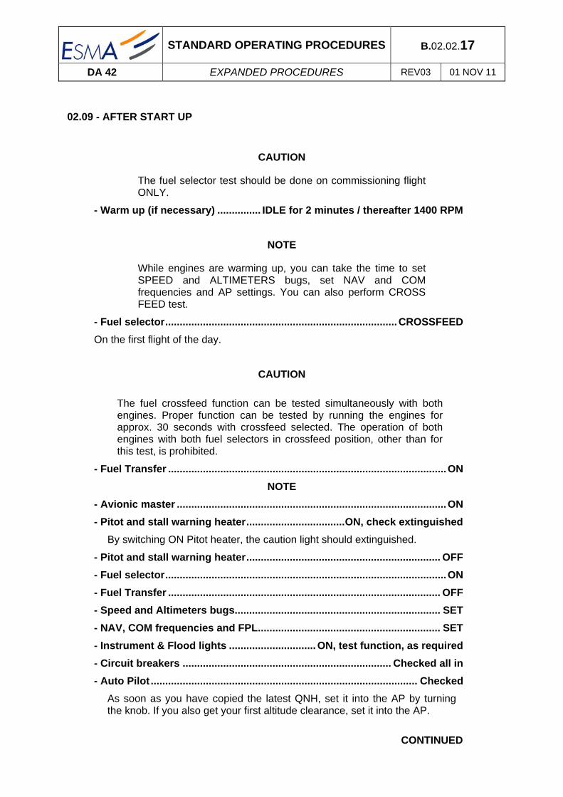
STANDARD OPERATING PROCEDURES B.02.02.17
DA 42 EXPANDED PROCEDURES REV03 01 NOV 11
02.09 - AFTER START UP
CAUTION
The fuel selector test should be done on commissioning flight ONLY.
- Warm up (if necessary) ............... IDLE for 2 minutes / thereafter 1400 RPM
NOTE
While engines are warming up, you can take the time to set SPEED and ALTIMETERS bugs, set NAV and COM frequencies and AP settings. You can also perform CROSS FEED test.
- Fuel selector ................................................................................ CROSSFEED
On the first flight of the day.
CAUTION
The fuel crossfeed function can be tested simultaneously with both engines. Proper function can be tested by running the engines for approx. 30 seconds with crossfeed selected. The operation of both engines with both fuel selectors in crossfeed position, other than for this test, is prohibited.
- Fuel Transfer ................................................................................................ ON
NOTE
- Avionic master ............................................................................................. ON
- Pitot and stall warning heater .................................. ON, check extinguished
By switching ON Pitot heater, the caution light should extinguished.
- Pitot and stall warning heater ................................................................... OFF
- Fuel selector ................................................................................................. ON
- Fuel Transfer .............................................................................................. OFF
- Speed and Altimeters bugs....................................................................... SET
- NAV, COM frequencies and FPL ............................................................... SET
- Instrument & Flood lights .............................. ON, test function, as required
- Circuit breakers ........................................................................ Checked all in
- Auto Pilot ............................................................................................ Checked
As soon as you have copied the latest QNH, set it into the AP by turning the knob. If you also get your first altitude clearance, set it into the AP.
CONTINUED

STANDARD OPERATING PROCEDURES B.02.02.18
DA 42 EXPANDED PROCEDURES REV03 01 NOV 11
02.10 - ECU TEST
This procedure should only be carried out on commissioning flight by the pilot at apron. However the instructor retains the possibility of having it carried out by the student for training purposes before aircraft being lined up on the runway.
- Parking brake ............................................................................................. SET
- Door warning (DOOR) ................................................. Checked no indication
- Annunciations / Engine / System Page ............................ OK / Normal range
Except pressure may be in the yellow range with a warm engine and power lever at idle.
NOTE
The following test sequence can be executed for both enginessimultaneously, or in sequence.
CAUTION
If the “L/R ECU A/B FAIL” does not illuminate and extinguishesduring the test sequence there is a malfunction in the enginecontrol system. Terminate flight.
The whole test procedure must be completed without any error.In case of an error terminate flight, even when the engineseems to be running smoothly after the test procedure.
CONTINUED

STANDARD OPERATING PROCEDURES B.02.02.19
DA 42 EXPANDED PROCEDURES REV03 01 NOV 11
FADEC test sequence:
- Power lever ................................................................................................ IDLE
- ECU test button .................................................................... Pressed and held
Annunciations in the following sequence:
- ECU A/B FAIL LIGHTS ................................................................................. ON
- Propeller RPM ................................................................................... Increased
- ECU A/B FAIL LIGHTS ............................................................................... OFF
- ECU B FAIL LIGHT ....................................................................................... ON
- Propeller RPM ............................................................. Decreased / Increased
- ECU B FAIL LIGHT ..................................................................................... OFF
- ECU A FAIL LIGHT ....................................................................................... ON
- Propeller RPM ............................................................. Decreased / Increased
- ECU A FAIL LIGHT ..................................................................................... OFF
- Propeller RPM ........................................................... above approx. 900 RPM
Test sequence completed
CAUTION
When switching from one ECU to the other a slight shake of theengine may occur. In case of longer dropouts of the engine, orif the engine stops during the test, terminate flight.
- ECU TEST BUTTON ........................................................................... Released
- ECU SWAP ............................................................................................. ECU B
- Engine ..................................................... Checked running without a change
- ECU SWAP ................................................................................... AUTOMATIC
NOTE
When switching from one ECU to the other a slight shake of theengine may occur.
CAUTION
Running the engine with the ECU SWAP on ECU B, other thanfor this test or in an emergency is prohibited. The engines control system redundancy is only given with the ECU SWAPset on AUTO.
SEE AFTER START UP CHECK LIST

STANDARD OPERATING PROCEDURES B.02.02.20
DA 42 EXPANDED PROCEDURES REV03 01 NOV 11
- Departure strategy .......................................................................... completed
Departure strategy schematic:
«Departure strategy
Aircraft integrity (preflight inspection completed, HIL, CDL, MEL)
Meteorology (specific weather for the T/O: crosswind, visibility, ceiling, QNH)
Notam on the departure airfield (taxiway, runway…)
Runway (Taxiing condition, expected runway, condition…)
Departure track (VFR: 1st reporting point and altitude. IFR: description of the departure expected)
Radio aids organisation
Departure strategy completed»
02.11 - TAXI
The taxi procedure as to be followed when taxi has been approved.
- Block time .......................................................................................... Recorded
- Taxi light ....................................................................................................... ON
The systematic lighting of taxi lights is an anti-collision precaution and it also informs ground personnel that the aircraft is about to move. In order not to forget this operation, it is a good idea to associate it with the release of parking brake.
- Brakes ..................................................................................................... Tested
Increase RPM to 1300 RPM then release parking brake while maintaining pressure on the pedals to test brakes. The pedal test is considered to be correct if the aircraft does not move.
During training flights the pilot should request right hand side brake test. The announcement should be as follow: “ON THE RIGHT THE CONTROLS FOR BRAKE TEST”
- Gyros .................................................................................................. Checked
Check the consistency of the directional gyro and emergency compass; check the stability of the backup artificial horizon and the coherence of indications on the turn coordinator. Those checks are performed while turning during taxi. During those checks the pilot announces the headings and attitudes (i.e.: For a right turn, you must announce “HEADINGS INCREASE, ATTITUDE STABLE, NEEDLE TO THE RIGHT, BALL TO THE LEFT, GYRO CHECK COMPLETED”).
CAUTION
When taxiing on a poor surface select the lowest possible RPMto avoid damage to the propeller from stones or similar items.
END OF TAXI PROCEDURE

STANDARD OPERATING PROCEDURES B.02.02.21
DA 42 EXPANDED PROCEDURES REV03 01 NOV 11
02.12 - BEFORE TAKE OFF
12.01 - Before Take Off
Available power check:
- Power lever ...................................................................... MAX for 10 seconds
- Annunciations .................................................................... OK / Normal range
- Instruments ............................................... Checked within the normal range
- RPM ................................................................ Stabilizes @ 2240 to 2300 RPM
- Load indication ......................................................... Stabilizes @ 90 to 100%
- Power lever ................................................................................................ IDLE
CAUTION
Under high temperature and high altitude conditions, load indications below 90% are possible. If the engine does notstabilize at the target RPM of 2240 to 2300 RPM terminateflight.
- IFR Departure Clearance ................................................................ Requested
Confirm that clearance is in accordance with departure strategy. Set altitude clearance and squawk.
- Doors & Door warning ............ Closed and locked & checked extinguished
- CREW & PAX ....................................................................................... Secured
- Trim .............................................................................................................. T/O
- Flight controls ................................................................................. Free travel
The pilot checks the free movement of the flight controls by moving the control column following a square (Start from its front stop, Left front stop, Left aft stop, Right aft stop, Right front stop.
- All flight instruments ......................................................................... Checked
The pilot checks normal indications on basic instruments (H.S.I., Turn Coordinator, Airspeed indicator, A.D.I., Altimeter, Vertical speed indicator).
- Powerplant instruments .................................................................... Checked
- Breakers ........................................................................................... Pushed in
- Flaps ............................................................................................................. UP
During normal operation take-off will be performed flaps UP.
CONTINUED

STANDARD OPERATING PROCEDURES B.02.02.22
DA 42 EXPANDED PROCEDURES REV03 01 NOV 11
- Departure briefing ........................................................................... completed
Departure briefing schematic:
«Departure briefing
T/O RWY and actual heading
T/O weight
T/O configuration (flaps and trim)
T/O associated speed ( V1/VR, initial climb, normal climb)
T/O altitudes (safety altitude and acceleration altitude)
In case of failure before V1 (Actions)
In case of failure after Vr (Trajectory)
Departure briefing completed»
SEE BEFORE TAKE-OFF CHECK LIST

STANDARD OPERATING PROCEDURES B.02.02.23
DA 42 EXPANDED PROCEDURES REV03 01 NOV 11
12.02 - Line up
The line up procedure is to be followed when cleared to line up.
- Pitot heater (Caution reset) ......................................................................... ON
The Pitot heater must be set ON in order to avoid errors while reading the compass.
- Landing light ................................................................................................ ON
- Compass ............................................................................................. Checked
The pilot checks that the compass indication stays in accordance with runway magnetic orientation.
- Annunciator panel ............................................................................. Checked
END OF LINE UP PROCEDURE

STANDARD OPERATING PROCEDURES B.02.02.24
DA 42 EXPANDED PROCEDURES REV03 01 NOV 11
02.13 - TAKE-OFF
- Take off time ................................................................. Recorded on Nav Log
The pilot announces take off time: «TAKE OFF AT … - TOP».
- Take off power ..................................................................................... Applied
The pilot applies take off power and confirms that throttle is fully pushed forward.
NOTE
The proper and symmetric performance of the engines at MAXshould be checked early during take-off run, so that the take-off can be aborted if necessary.
While monitoring aircraft acceleration and maintaining centre line the pilot checks the various engine parameters and announces « NORMAL PARAMETERS » if they are consistent with the following values:
T/O Load ................................................ Checked
Airspeed indicator ....................................... Active
Annunciator panel .................................. Checked
He keeps his hand on control levers until V1/VR.
- Rotation speed –“ ROTATION” ..................................................... Announced
When the pilot reads rotation speed Vr on the airspeed indicator he announces « ROTATION » and pulls slightly on the control column to set the initial climb pitch angle.
- Airspeed for initial climb .......................................................................... Vyse
- “Positive climb” ............................................................................. Announced
The pilot announces “positive climb” as soon as he can read a positive climb on the variometer.
- “Brakes” ......................................................................................... Announced
The pilot announces “brakes” and presses the brake pedals in order to stop wheel rotation (risk of vibration).
- “Landing gear” .................................................. UP, checked unsafe light off
The pilot announces “gear up”. Do not press brake pedals while landing gear is operating.
- Initial climb speed ..................................................................................... Vyse
END OF TAKE-OFF PROCEDURE

STANDARD OPERATING PROCEDURES B.02.02.25
DA 42 EXPANDED PROCEDURES REV03 01 NOV 11
02.14 - AFTER TAKE-OFF
Above 400 ft AAL (VFR) or 1500 ft AAL (IFR):
- Normal climb speed ............................................................................. 90 KIAS
- Climb power ................................................................................................. Set
When indicated airspeed reaches 90 kts, the pilot announces «90 kts, CLIMB POWER» and sets the engine parameters for the climb.
LOAD ........................................................................................ 95%
- Engine parameters ........................................................... Within green range
- Altimeter ............................................................................. Set and compared
According to the clearance he has been given, the pilot sets his altimeter to QNH or to 1,013.25hPa then he compares the two altimeters.
- Landing light .............................................................................................. OFF
The landing light will not be switch OFF before 3000 ft AGL or cruise (if cruising altitude is less than 3000 ft AGL)
- Annunciations / Engine / System page .......................................... Monitored
SEE AFTER TAKE-OFF CHECK LIST
CAUTION
If the oil temperature and/or coolant temperature reaches theyellows range during climb, flight should be continued with theairspeed increase by 10 kts and power reduce by 10 %(reduced climb rate) for better engine cooling.

STANDARD OPERATING PROCEDURES B.02.02.26
DA 42 EXPANDED PROCEDURES REV03 01 NOV 11
02.15- CRUISE
15.01 - Cruise
The CRUISE procedure begins before reaching a stabilized cruise path.
- Cruise altitude ............................................................. Captured and checked
The pilot captures cruise altitude, complying with the rate of climb lead in rule:
Anticipation starts as soon as difference between current altitude and cruise altitude reaches 10 % of rate of climb.
For instance: with a rate of climb of 500 ft/min, lead in starts 50 ft before selected altitude or flight level.
- Cruise power ................................................................................................ Set
When cruise speed -15 kts has been reached, the pilot sets engine parameters according to the type of cruise selected.
ESMA recommends a 60 % Load for cruise.
- Annunciations / Engine / System page ............................................ Checked
The pilot carries out a check on all engine parameters.
- Fuel ..................................................................................................... Checked
The fuel quantity is checked accordingly with the planned fuel quantity computed during flight preparation.
- TAS ................................................................................ Readied or Computed
- Wind ............................................................................. Evaluated and readied
The wind is taken into consideration during flight preparation, using meteorological forecasts (altitude wind and temperature charts).
In flight, evaluate the drift angle visually or using the track computed by the GPS. The ground speed is assessed after a navigation leg or directly using the GPS.
- ETA ......................................................................... Evaluated and announced

STANDARD OPERATING PROCEDURES B.02.02.27
DA 42 EXPANDED PROCEDURES REV03 01 NOV 11
15.02 - Waypoint
The Waypoint procedure begins when the waypoint “TO” is identified, at least 1 minute before overflying it.
- Next track, next heading ............................................................... Announced
The pilot reads the next track accordingly to his nav log and computes the corresponding heading (may be computed during flight preparation and refreshed in flight).
- Next leg ............................................................................................... Prepared
To prepare the next leg:
Check if there are altitude changes.
Preset next Communication frequency
Preset next Navigation Aids
- When overflying the waypoint ........................................................ TOP - turn
When overflying the waypoint, the pilot starts the stop watch for the next leg, notes the overflying waypoint time and flies the aircraft to the computed heading (30° bank angle is recommended).
- Altitude ......................................................................... Changed if necessary
Verify and adjust if necessary the altimeter setting. Change altitude (climb or descent) if required.
- Fuel ..................................................................................................... Checked
The fuel quantity is checked accordingly with the estimated fuel quantity computed.
- Radio aids ..................................................................................................... Set
Activate if necessary prepared frequencies (VHF COMM & NAV) adjust VOR radial and GPS.
- Nav log ...................................................................................................... Filled
Fill nav log data:
Waypoint overflying actual time
Next waypoint estimated overflying time and fuel quantity
END OF CRUISE PROCEDURES

STANDARD OPERATING PROCEDURES B.02.02.28
DA 42 EXPANDED PROCEDURES REV03 01 NOV 11
02.16 - DESCENT
16.01 - Before descent
The BEFORE DESCENT procedure is initiated before beginning the descent, when weather conditions at destination have been copied.
- TOD ................................................................................................... Computed
- Altimeter ............................................................................. Set and compared
The altimeter is set on destination airfield QNH if descent is planned to an altitude or remains standard (1,013.25hPa) if descent is planned to a flight level.
- Altimeter bugs .............................................................................. Set DA/MDA
- Arrival briefing ................................................................................ Completed
The arrival briefing consists in describing the complete flight path from descent to landing or go-around, in chronological order and with featuring elements.
“Arrival Briefing”
Is airfield reachable?
TOD at a DME distance of ___ descending to ___ ft
The MSA is ___ ft
We can expect a (ILS, VOR, DME, ADF…)___ arrival
For runway ___ (QFU); Flow chart N°___ dated from ___ (date of issue)
Description trajectory
Weather condition at destination (Ceiling, visibility)
Radio Aids (set & checked)
Minimum associated speed and altitude (set bugs)
Procedure in case of missed approach
Total fuel ___; We can hold ___ minutes
“Arrival Briefing completed”
However this briefing is not a priority item and should not cause path monitoring to be neglected, nor should it delay the descent. If the weather conditions at destination airfield are not known at the time of the briefing, the latter should be carried out using information known at the time, and updated when the weather conditions are later received.
END OF BEFORE DESCENT PROCEDURE

STANDARD OPERATING PROCEDURES B.02.02.29
DA 42 EXPANDED PROCEDURES REV03 01 NOV 11
16.02 - Descent
Descent is carried out at a fixed rate of 500ft/mn. Speed will depend on the turbulence encountered. VNO in smooth air.
- Annunciation / Engine / System page ....................... Adjusted and Checked
Throughout descent, the pilot constantly adjusts power to avoid operating above maximum setting and complying with the descent law retained. 500 ft/min fits with a speed of 155 KT for normal descent; that value should be kept up if it is considered to be practicable, that corresponds to a power setting (load) of 55%.
750 ft/min is a high speed rate of descent to be considered as maximum in normal operation.
NOTE
Power lever can be adjusted as required below 5000 ft but notless than 30 % above 5000 ft.
WARNING
Engine combustion may stop unrecognized during descent with idle power at altitudes above 5000 ft with outside airtemperatures below -10°C.
END OF DESCENT PROCEDURE

STANDARD OPERATING PROCEDURES B.02.02.30
DA 42 EXPANDED PROCEDURES REV03 01 NOV 11
02.17 - APPROACH
Approach procedure is initiated when altimeter has been changed to airfield QNH. In IFR, it can also be referred to initial segment.
- Altimeter ..................................................................... set QNH and compared
As soon as the pilot is cleared to an altitude or a height he sets his altimeter to airfield QNH announcing loudly “QNH ___ hPa”, then he compares the two altimeters.
- Landing Light ............................................................................................... ON
- Fuel selector ................................................................................. Checked ON
- Speed and Altitude bugs ............................................................................. Set
- Brakes ............................................................................................ Pressurized
The pilot presses brake pedals to check that brake system is pressurized. He then removes his feet from brake pedals until landing.
SEE APPROACH CHECK LIST
02.18 - LEVELLED APPROACH
The levelled approach procedure refers in VFR to the downwind leg. In IFR it refers to the intermediate segment.
- Flaps ........................................................................................................... APP
The IAS must be below VFEapp
At retained airspeed for flap extension, the pilot announces “SPEED ___ kts, Flaps APP”;
He observes the execution of the sequence, and announces “FLAPS APP SET”
- Landing gear ...................................................................... Down / 3 GREENS
- Load ............................................................................................................ 70%
END OF LEVELLED APPROACH PROCEDURE

STANDARD OPERATING PROCEDURES B.02.02.31
DA 42 EXPANDED PROCEDURES REV03 01 NOV 11
02.19 - LANDING
- Rudder Trim .......................................................................................... Neutral
- Flaps ........................................................................................................... LDG
The IAS must be below VFEldg
At the speed retained for flap extension, the pilot announces “SPEED ___ kts, Flaps LDG”;
He observes the execution of the sequence, and announces “FLAPS LDG SET”
- Missed approach altitude .............................................................. SELECTED
SEE LANDING CHECK LIST
02.20 - GO AROUND
The go around procedure is performed in IFR when reaching Decision Altitude or MAPt, without runway visual references. It may also occur when the aircraft is reaching the stabilization point if any of the final approach parameter does not meet the standard:
Axis, slope, speed, configuration, Landing Check-List not completed.
- Pitch attitude ............................................................................................... + 5°
- Power lever ................................................................................................ MAX
- Airspeed ........................................................................ Min 1.2 Vs Flaps APP
- Flaps ........................................................................................................... APP
When a positive rate of climb is established:
- Landing gear ........................................................ UP (check unsafe light off)
- Airspeed ......................................................................................... Min 1.2 Vs1
- Flaps ............................................................................................................. UP
- Pitch attitude ............................................................................................. + 11°
Then continue with after take-off procedure
SEE AFTER TAKE-OFF CHECK LIST

STANDARD OPERATING PROCEDURES B.02.02.32
DA 42 EXPANDED PROCEDURES REV03 01 NOV 11
02.21 - AFTER LANDING
The AFTER LANDING procedure is initiated after having vacated the runway.
- Trim .............................................................................................................. T/O
- Flaps ............................................................................................................. UP
- Transponder ............................................................................................. STBY
- Pitot heater ................................................................................................. OFF
- Landing light .............................................................................................. OFF
- Taxi light ....................................................................................................... ON
The pilot retracts the flaps in order to prevent them from being damaged by gravel thrown up by the propeller wash.
SEE AFTER LANDING CHECK LIST
STANDARD OPERATING PROCEDURES B.02.02.33
DA 42 EXPANDED PROCEDURES REV03 01 NOV 11
02.22 - PARKING
The PARKING procedure is initiated when the aircraft comes to a stop at parking area.
- Taxi light ..................................................................................................... OFF
- Parking brake ............................................................................................. SET
- Power lever ......................................................................... IDLE for 2 minutes
- Engine / System page ........................................................................ Checked
- ELT .................................................. Checked not transmitting on 121.5 MHz
- Avionic master ........................................................................................... OFF
- Position lights ............................................................................................ OFF
- Engine master ............................................................................................ OFF
- Anti-collision lights (ACL) ......................................................................... OFF
- Electric master ............................................................................ OFF- Key out
CAUTION
Before shut-down the engine must run for at least 2 minuteswith the power at IDLE to avoid heat damage of the turbocharger.
Do not shut down an engine with the fuel selector valve. Thehigh pressure fuel pump can otherwise be damaged.
SEE PARKING CHECK LIST

STANDARD OPERATING PROCEDURES B.02.02.34
DA 42 EXPANDED PROCEDURES REV03 01 NOV 11
02.23 - NIGHT STOP
The NIGHT STOP procedure is carried out in addition to the PARKING procedure, to secure the aircraft on the ground, after the last flight of the day. According to weather forecasts, the pilot will decide to line the aircraft face to the prevailing wind forecast (if applicable) and with flaps retracted.
- Forward chock ................................................................................ Positioned
- Parking brake ................................................................... Applied and locked
- Controls ................................................................................................. Locked
- Pitot head cover .............................................................................. Positioned
- Stall warning cover ......................................................................... Positioned
- Aircraft docking .............................................................................. Completed
Out of courtesy, leave the aircraft clean and ordered.
In order to detect any faults which could require immediate attention from the maintenance department, the pilot walks around the aircraft to check out its general condition, particularly that of tires and propeller.
SEE SECURING AIRCRAFT CHECK LIST
02.24 - FLIGHT IN RAIN
NOTE
Performance deteriorates in rain; this applies particularly to thetake-off distance and to the maximum horizontal speed. Theeffect on the flight characteristics is minimal.
02.25 - REFUELLING
CAUTION
Before refuelling, the airplane must be connected to electricalground. Grounding points: unpainted areas on steps, left andright. Refer to section B.06 for approved fuel grades.

FLIGHT PLANNING B.05.03.01
DA 42 IN FLIGHT PLANNING REV03 01 NOV 11
IN-FLIGHT PLANNING
03.01 - LIMITATIONS
WEIGHT SPEED (KIAS)
MTOW: 1785 kg VNE: 194
MLW: 1700 kg VNO: 155
Nose Baggage Compartment : 30 kg VA:124 (1700 kg) 121 (1250 kg)
Cockpit Baggage Compartment : 45 kg VFE:APP: 137 LDG: 111
VLOR: 156
WIND VLOE: 111
Maximum crosswind: 20 kts VLE: 194
Maximum tailwind: 10 kts
STALL SPEEDS
1700 kg Bank Angle
0° 30° 45° 60°
Flaps
UP 62 67 76 92
T/O 59 64 72 87
LDG 55 60 68 84
1785 kg Bank Angle
0° 30° 45° 60°
Flaps
UP 64 69 78 95
T/O 61 66 74 90
LDG 57 62 70 86

FLIGHT PLANNING B.05.03.02
DA 42 IN FLIGHT PLANNING REV03 01 NOV 11
BANK LIMITATIONS ( maxi)
Speed 1.1 VS 1.2 VS 1.3 VS 1.45 VS
Φ maxi 5° 10° 20° 37°
Don’t use during normal operation.
03.02 - CRUISE POWER SETTINGS
Load (%)
Fuel flow (US gal/H)
ONE ENGINE
Fuel flow (US gal/H)
2 ENGINES
Cruise Flaps UP
(TAS @ 4000’)
30% 2.25 5.5
40% 2.9 5.8
50% 3.6 7.2
60% 4.4 8.8 131 kts
70% 5.25 10.5 140 kts
80% 6.2 12.4 147 kts
90% 7.2 14.4 154 kts
100% 8.3 16.6

FLIGHT PLANNING B.05.03.03
DA 42 IN FLIGHT PLANNING REV03 01 NOV 11
03.03 - FUEL FLOW DIAGRAM
CAUTION
The diagram shows the fuel flow per hour for one engine
NOTE
The fuel calculation on the FUEL CALC portion of the G1000 MFD does NOT use the airplane’s fuel quantity indicators. The values shown are numbers which are calculated from the last fuel quantity update done by the pilot and actual fuel flow data. Therefore, the endurance and range data is for information only, and must not be used for flight planning.

FLIGHT PLANNING B.05.03.04
DA 42 IN FLIGHT PLANNING REV03 01 NOV 11
03.04 - INTERNATIONAL STANDARD ATMOSPHERE

FLIGHT PLANNING B.05.03.05
DA 42 IN FLIGHT PLANNING REV03 01 NOV 11
03.05 - TAKE-OFF DISTANCE OVER 50 FT OBSTACLE DIAGRAM

FLIGHT PLANNING B.05.03.06
DA 42 IN FLIGHT PLANNING REV03 01 NOV 11

FLIGHT PLANNING B.05.03.07
DA 42 IN FLIGHT PLANNING REV03 01 NOV 11
03.06 - TAKE-OFF GROUND ROLL DIAGRAM

FLIGHT PLANNING B.05.03.08
DA 42 IN FLIGHT PLANNING REV03 01 NOV 11

FLIGHT PLANNING B.05.03.09
DA 42 IN FLIGHT PLANNING REV03 01 NOV 11
03.07 – CLIMB PERFORMANCE – TAKE OFF CLIMB

FLIGHT PLANNING B.05.03.10
DA 42 IN FLIGHT PLANNING REV03 01 NOV 11

FLIGHT PLANNING B.05.03.11
DA 42 IN FLIGHT PLANNING REV03 01 NOV 11
03.08 – CLIMB PERFORMANCE – CRUISE CLIMB

FLIGHT PLANNING B.05.03.12
DA 42 IN FLIGHT PLANNING REV03 01 NOV 11

FLIGHT PLANNING B.05.03.13
DA 42 IN FLIGHT PLANNING REV03 01 NOV 11
03.09 – ONE ENGINE INOPERATIVE CLIMB / DESCENT

FLIGHT PLANNING B.05.03.14
DA 42 IN FLIGHT PLANNING REV03 01 NOV 11
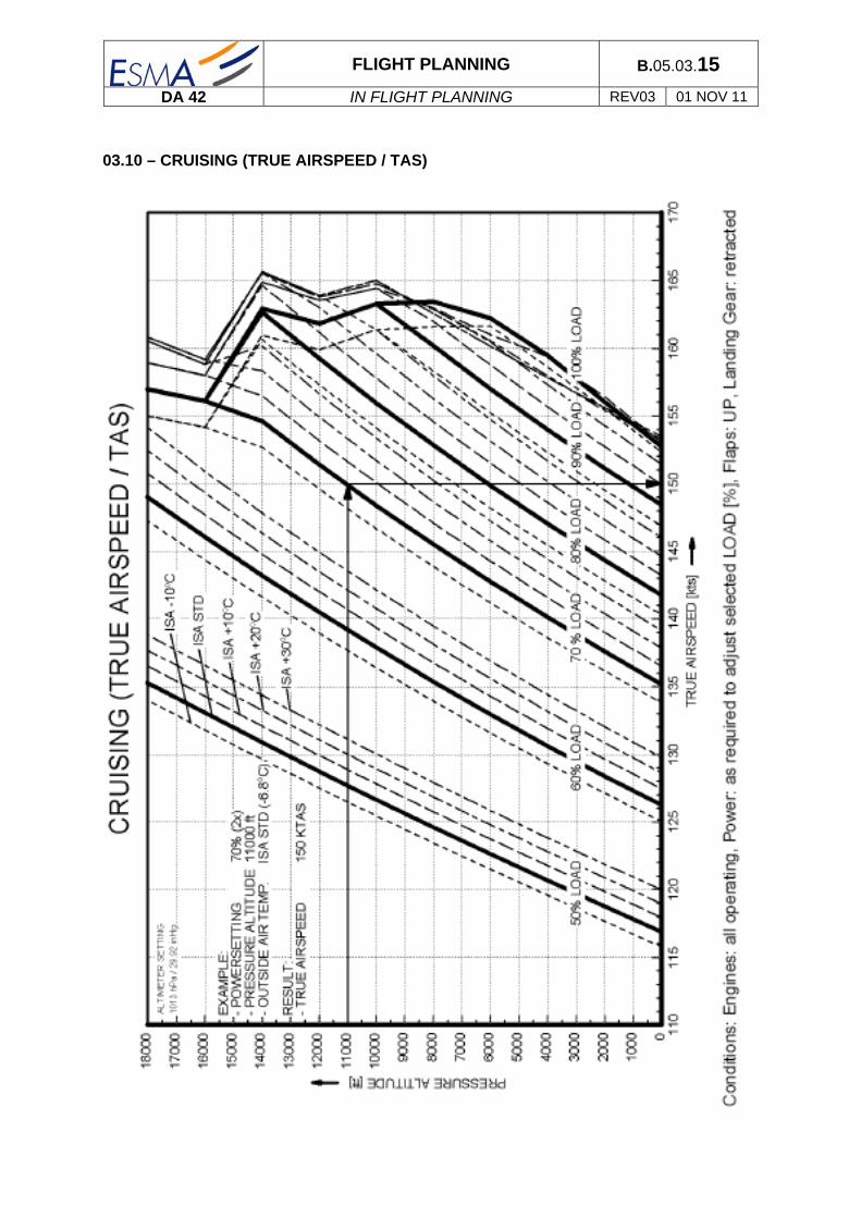
FLIGHT PLANNING B.05.03.15
DA 42 IN FLIGHT PLANNING REV03 01 NOV 11
03.10 – CRUISING (TRUE AIRSPEED / TAS)

FLIGHT PLANNING B.05.03.16
DA 42 IN FLIGHT PLANNING REV03 01 NOV 11
03.11 – LANDING DISTANCE GROUND ROLL

FLIGHT PLANNING B.05.03.17
DA 42 IN FLIGHT PLANNING REV03 01 NOV 11
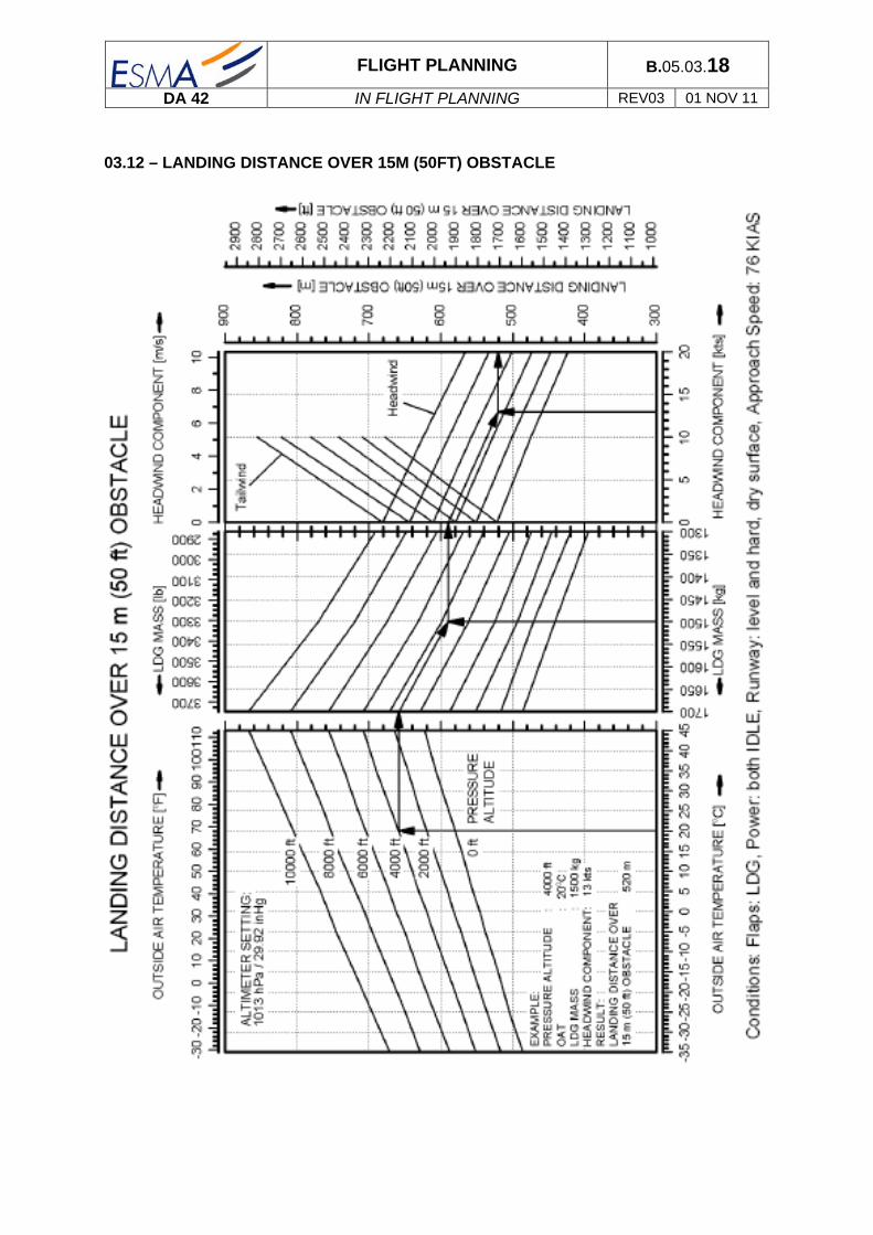
FLIGHT PLANNING B.05.03.18
DA 42 IN FLIGHT PLANNING REV03 01 NOV 11
03.12 – LANDING DISTANCE OVER 15M (50FT) OBSTACLE

FLIGHT PLANNING B.05.03.19
DA 42 IN FLIGHT PLANNING REV03 01 NOV 11

FLIGHT PLANNING B.05.03.20
DA 42 IN FLIGHT PLANNING REV03 01 NOV 11
Intentionally left blank

MEL B.09.02.01
DA 42 MEL REV 00 01 APR 07
MINIMUM EQUIPMENT LIST
This section has specific page number in order to show the ATA code and allow a rapid search of desired item. The figure below gives an example of MEL page number: MEL contents: ATA21 ...... Air conditioning ............................................................................... B.09.02.A21.01 ATA22 ...... Auto Pilot ........................................................................................ B.09.02.A22.01 ATA23 ...... Communications ............................................................................. B.09.02.A23.01 ATA24 ...... Electrical power .............................................................................. B.09.02.A24.01 ATA25 ...... Equipments and furnishing ............................................................. B.09.02.A25.01 ATA26 ...... Fire protection ................................................................................. B.09.02.A26.01 ATA27 ...... Flight controls ................................................................................. B.09.02.A27.01 ATA28 ...... Fuel system .................................................................................... B.09.02.A28.01 ATA30 ...... Ice protection .................................................................................. B.09.02.A28.01 ATA31 ...... Indicating systems .......................................................................... B.09.02.A31.01 ATA32 ...... Landing gear ................................................................................... B.09.02.A32.01 ATA33 ...... Lights .............................................................................................. B.09.02.A33.01 ATA34 ...... Navigation ....................................................................................... B.09.02.A34.01 ATA52 ...... Doors .............................................................................................. B.09.02.A52.01 ATA77 ...... Engine indicating ............................................................................ B.09.02.A77.01
B.09.02.A52.02
Section (B.09)
Chapter (02)
ATA (ATA 52 : Doors)
Page (02)

MEL B.09.02.A21.01
DA 42 MEL REV 00 01 APR 07
INOP
INOP
AIR CONDITIONING
ATA 21 1 2 - DURATION OF APPLICATION
3 - NUMBER INSTALLED
INOPERATIVE SYSTEM OR EQUIPMENT DESIGNATION
00 4 - NUMBER REQUIRED FOR FLIGHT
00 5 - REMARKS OR CONDITIONS
21.1 Cabin heater
1
0
Can be inoperative if flight conditions are without rain falls, high relative humidity or with negative temperatures.
21.2 Lever DEFROST/FLOOR 1 0 Can be inoperative if cabin heater is operative
and flight conditions are without rain falls, high relative humidity or with negative temperatures.
21.3 Cabin ventilation 1 0 Can be inoperative if cabin heater is not
necessary (see 21.1).

MEL B.09.02.A21.02
DA 42 MEL REV 00 01 APR 07
Associated procedures

MEL B.09.02.A22.01
DA 42 MEL REV 00 01 APR 07
INOP
AUTO PILOT
ATA 22 1 2 - DURATION OF APPLICATION
3 - NUMBER INSTALLED
INOPERATIVE SYSTEM OR EQUIPMENT DESIGNATION
00 4 - NUMBER REQUIRED FOR FLIGHT
00 5 - REMARKS OR CONDITIONS
22.1 Auto Pilot System
1
0

MEL B.09.02.A22.02
DA 42 MEL REV 00 01 APR 07
Associated procedures

MEL B.09.02.A23.01
DA 42 MEL REV 00 01 APR 07
COMMUNICATIONS
ATA 23 1 2 - DURATION OF APPLICATION
3 - NUMBER INSTALLED
INOPERATIVE SYSTEM OR EQUIPMENT DESIGNATION
00 4 - NUMBER REQUIRED FOR FLIGHT
00 5 - REMARKS OR CONDITIONS
23.50.1 Intercom
1
1
At least the pilot intercom must works during a non training flight.
At least the pilot and the instructor intercom must work during a training flight.
23.50.2 PTT switch 2 1 The right PTT switch can be inoperative if the left PTT switch works properly.
23.61.1 Electrostatic dischargers
7 5 One of the two electrostatic dischargers located on the left and/or right wing tip can be inoperative.

MEL B.09.02.A23.02
DA 42 MEL REV 00 01 APR 07
Associated procedures

MEL B.09.02.A24.01
DA 42 MEL REV 00 01 APR 07
INOP
INOP
INOP
ELECTRICAL POWER
ATA 24 1 2 - DURATION OF APPLICATION
3 - NUMBER INSTALLED
INOPERATIVE SYSTEM OR EQUIPMENT DESIGNATION
00 4 - NUMBER REQUIRED FOR FLIGHT
00 5 - REMARKS OR CONDITIONS
24.36.1 Ampere meter (AMPERE)
1
0
Can be inoperative for a VFR day flight.
24.36.2 Voltmeter (VOLT) 1 0 Can be inoperative for a VFR day flight.
Can be inoperative for a VFR night flight if the Voltmeter function of the chronometer is operative
24.36.3 Voltmeter (Chronometer)
1 0 Can be inoperative for a VFR day flight.
Can be inoperative for a VFR night flight if the Voltmeter indication on the AED (VOLT) is operative

MEL B.09.02.A24.02
DA 42 MEL REV 00 01 APR 07
Associated procedures

MEL B.09.02.A25.01
DA 42 MEL REV 00 01 APR 07
INOP
EQUIPMENT AND FURNISHING
ATA 25 1 2 - DURATION OF APPLICATION
3 - NUMBER INSTALLED
INOPERATIVE SYSTEM OR
EQUIPMENT DESIGNATION
00 4 - NUMBER REQUIRED FOR FLIGHT
00 5 - REMARKS OR CONDITIONS
25.11.1 Front left Seat
Seat belt 1 1 NO GO
Rudder pedal adjuster 1 0 The adjuster can be inoperative if it is locked in a position that suits to the pilot.
25.11.2 Front right Seat
Seat belt 1 0 (P) Unservicable seat
Rudder pedal adjuster 1 0 The adjuster can be inoperative if it is locked in a position that suits to the instructor. It can be locked in any position if the occupant of the seat is not a crew member.
25.21 Rear Seats
Seat belt 2 0 Each seat which seat belt is inoperative is unservicable
25.63 ELT 1 0 Can be inoperative for a VFR day flight if the flight is
performed at less than 25 NM from departure airfield and the pilot is always in communication with ATC.

MEL B.09.02.A25.02
DA 42 MEL REV 00 01 APR 07
Associated procedures
ATA 25 1 2 - NUMBER INSTALLED
INOPERATIVE SYSTEM OR EQUIPMENT DESIGNATION
00 3 - NUMBER REQUIRED FOR FLIGHT
00 4 - REMARKS OR CONDITIONS
25.11.1 Front left Seat
Seat belt 1 1 NO GO
Rudder pedal adjuster 1 0 The adjuster can be inoperative if it is locked in a position that suits to the pilot.
25.11.2 (P) If the front right seat in unoccupied and there are passenger seated on rear seats, pay attention to the aircraft weights and balance.

MEL B.09.02.A25.03
DA 42 MEL REV 00 01 APR 07
EQUIPMENT AND FURNISHING
ATA 25 1 2 - DURATION OF APPLICATION
3 - NUMBER INSTALLED
INOPERATIVE SYSTEM OR EQUIPMENT DESIGNATION
00 4 - NUMBER REQUIRED FOR FLIGHT
00 5 - REMARKS OR CONDITIONS
25.64 Life vests 4 0 Can be inoperative or missing if:
The aircraft doesn’t overfly water surface so that in case of engine failure it can not land on suitable ground surface.
And the flight is performed at less than 50 NM away from the shore.
In all other case there must be 1 operative life vest for each occupant of the aircraft.
25.67 flash-light 1 0 Can be inoperative or missing for a VFR day flight

MEL B.09.02.A25.04
DA 42 MEL REV 00 01 APR 07
Associated procedures

MEL B.09.02.A26.01
DA 42 MEL REV 00 01 APR 07
FIRE PROTECTION
ATA 26 1 2 - DUARTION OF APPLICATION
3 - NUMBER INSTALLED
INOPERATIVE SYSTEM OR EQUIPMENT DESIGNATION
00 4 - NUMBER REQUIRED FOR FLIGHT
00 5 - REMARKS OR CONDITIONS
26.24 Portable fire extinguisher
1 0 Departure without any restrictions.

MEL B.09.02.A26.02
DA 42 MEL REV 00 01 APR 07
Associated procedures

MEL B.09.02.A27.01
DA 42 MEL REV 00 01 APR 07
INOP
INOP
FLIGHT CONTROLS
ATA 27 1 2 - DURATION OF APLLICATION
3 - NUMBER INSTALLED
INOPERATIVE SYSTEM OR EQUIPMENT DESIGNATION
00 4 - NUMBER REQUIRED FOR FLIGHT
00 5 - REMARKS OR CONDITIONS
27.35 Stall warning 1 0 Can be inoperative ONLY for training flight.
27.51 Flaps control 1 0 (P) Can be inoperative if flaps position is checked UP, only for
a technical flight.
27.56 Flaps position indicating lights
3 0 Can be inoperative if flaps position is visualy checked
during flight.

MEL B.09.02.A27.02
DA 42 MEL REV 00 01 APR 07
Associated procedures
ATA 27 1 2 - NUMBER INSTALLED
INOPERATIVE SYSTEM OR EQUIPMENT DESIGNATION
00 3 - NUMBER REQUIRED FOR FLIGHT
00 4 - REMARKS OR CONDITIONS
27.35 Stall warning 1 0 Can be inoperative but for training flight.
27.51 (P) Check take off and landing limitations and performances

MEL B.09.02.A28.01
DA 42 MEL REV 02 15 AUG 08
INOP
INOP
FUEL SYSTEM
ATA 28 1 2 - DURATION OF APPLICATION
3 - NUMBER INSTALLED
INOPERATIVE SYSTEM OR EQUIPMENT DESIGNATION
00 4 - NUMBER REQUIRED FOR FLIGHT
00 5 - REMARKS OR CONDITIONS
28.16 Fuel transfer pump 2 0
28.17 Draining valves 6 6 NO GO
Must be operatives without fuel leaks.
28.41 Fuel gauges (AED) 2 1 (P) The auxiliary tank gauge can be inoperative if the main
tank gauge is operative and: tanks are full or the fuel quantity memaining is checked visually using the alternate mean before the flight.
28.44 Fuel flow (AED) 1 0 (P)

MEL B.09.02.A28.02
DA 42 MEL REV 02 15 AUG 08
Associated procedures
ATA 28 1 2 - NUMBER INSTALLED
28.17 Draining valves 3 3
28.41 (P) An accurate fuel flight management must be achieved using the fuel flow indicator to respect the imbalance limitation within the two tanks (9 US gal max). The fuel remaining quantity check must be performed using the fuel alternate mean prior to flight operation.
28.44 (P) Fuel flight management must be achieved using the engine performance diagram

MEL B.09.02.A30.01
DA 42 MEL REV 00 01 APR 07
INOP
ICE PROTECTION
ATA 30 1 2 - DURATION OF APPLICATION
3 - NUMBER INSTALLED
INOPERATIVE SYSTEM OR EQUIPMENT DESIGNATION
00 4 - NUMBER REQUIRED FOR FLIGHT
00 5 - REMARKS OR CONDITIONS
30.1 De-icing system C 1 0 Can be inoperative if not flying into forecast or known icing conditions.
30.06 Stall Warning Heater C 1 0 Can be inoperative if not flying into forecast or known icing conditions.
30.15 Pitot Heater C 1 0 VFR flight is permitted if not flying into forecast or know icing conditions.

MEL B.09.02.A30.02
DA 42 MEL REV 00 01 APR 07
Associated procedures
ATA 28 1 2 - NUMBER INSTALLED

MEL B.09.02.A31.01
DA 42 MEL REV 00 01 APR 07
INOP
INDICATING SYSTEMS
ATA 31 1 2 - DURATION OF APPLICATION
3 - NUMBER INSTALLED
INOPERATIVE SYSTEM OR EQUIPMENT DESIGNATION
00 4 - NUMBER REQUIRED FOR FLIGHT
00 5 - REMARKS OR CONDITIONS
31.21 Clock
Chronometer 1 0 Departure without restriction if the pilot owns an operative rest watch.
Outside air thermometer 1 0 Can be inoperative if the flight is not planned at an altitude or flight level where a negative temperature or a temperature near 0°C can be expected, and with visible humidity (Fog, Mist, Clouds, rain, snow …).

MEL B.09.02.A31.02
DA 42 MEL REV 00 01 APR 07
Associated procedures

MEL B.09.02.A32.01
DA 42 MEL REV 00 01 APR 07
INOP
LANDING GEAR
ATA 32 1 2 - DURATION OF APPLICATION
3 - NUMBER INSTALLED
INOPERATIVE SYSTEM OR EQUIPMENT DESIGNATION
00 4 - NUMBER REQUIRED FOR FLIGHT
00 5 - REMARKS OR CONDITIONS
32.44 Parking brake 1 0 (P) Can be inoperative if a technical flight is planned.

MEL B.09.02.A32.02
DA 42 MEL REV 00 01 APR 07
Associated procedures
ATA 32 1 2 - NUMBER INSTALLED
INOPERATIVE SYSTEM OR EQUIPMENT DESIGNATION
00 3 - NUMBER REQUIRED FOR FLIGHT
00 4 - REMARKS OR CONDITIONS
32.44 (P) Chocks must be onboard the aircraft for the flight.

MEL B.09.02.A33.01
DA 42 MEL REV 00 01 APR 07
INOP
INOP
INOP
INOP
INOP
INOP
INOP
LIGHTS
ATA 33 1 2 - DURATION OF APPLICATION
2 - NUMBER INSTALLED
INOPERATIVE SYSTEM OR EQUIPMENT DESIGNATION
00 3 - NUMBER REQUIRED FOR FLIGHT
00 4 - REMARKS OR CONDITIONS
33.12 Reading lights 3 0 Can be inoperative if a VFR day flight is planned.
In the case of a VFR night flight, the Pilot reading light must be operative.
33.13 Instrument panel flood lighting (FLOOD)
1 0 Can be inoperative if a VFR day flight is planned.
33.14 Instrument lighting (INTRUMENT)
1 0 Can be inoperative if a VFR day flight is planned.
33.41 Navigation lights (POSITION)
3 0 Can be inoperative if a VFR day flight is planned.
33.42 Anti-collision lights (STROBE)
2 0 Can be inoperative if a VFR day flight is planned.
33.44 Landing lights (LANDING)
1 0 Can be inoperative if a VFR day flight is planned.
Can be inoperative at night if the taxi light is operative
33.44 Taxi lights (TAXI) 1 0 Can be inoperative if a VFR day flight is planned.
Can be inoperative at night if the landing light is operative

MEL B.09.02.A33.02
DA 42 MEL REV 00 01 APR 07
Associated procedures

MEL B.09.02.A34.01
DA 42 MEL REV 00 01 APR 07
INOP
INOP
INOP
INOP
NAVIGATION
ATA 34 1 2 - DURATION OF APPLICATION
3 - NUMBER INSTALLED
INOPERATIVE SYSTEM OR EQUIPMENT DESIGNATION
00 4 - NUMBER REQUIRED FOR FLIGHT
00 5 - REMARKS OR CONDITIONS
34.11 Pitot Static
Pitot Heater 1 0 Can be inoperative if the VFR day flight is not planned at an
altitude or flight level where a negative temperature or a temperature near 0°C can be expected, and with visible humidity (Fog, Mist, Clouds, rain, snow …).
Alternate Static valve 1 0 Can be inoperative if a VFR day flight is planned.
34.20.1 Attitude indicator 1 0 Can be inoperative if a VFR day flight is planned.
34.20.3 Turn and bank indicator
1 0 The turn indicator can be inoperative if a VFR day flight is
planned.
If the bank indicator is inoperative: NO GO

MEL B.09.02.A34.02
DA 42 MEL REV 00 01 APR 07
Associated procedures

MEL B.09.02.A34.03
DA 42 MEL REV 00 01 APR 07
INOP
INOP
INOP
NAVIGATION (Cont’d)
ATA 34 1 2 - DURATION OF APPLICATION
3 - NUMBER INSTALLED
INOPERATIVE SYSTEM OR
EQUIPMENT DESIGNATION
00 4 - NUMBER REQUIRED FOR FLIGHT
00 5 - REMARKS OR CONDITIONS
34.32 ILS 1 0 Can be inoperative if a VFR flight is planned.
34.51 VOR 1 0 Can be inoperative if a VFR day flight with visual contact with
ground is planned.
If special VFR, VFR on TOP or Night VFR is expected: NO GO
34.54 Transponder 1 0 Can be inoperative if a VFR day flight is planned
34.59 GPS 1 0 Can be inoperative without any restrictions.

MEL B.09.02.A34.04
DA 42 MEL REV 00 01 APR 07
Associated procedures

MEL B.09.02.A52.01
DA 42 MEL REV 00 01 APR 07
DOORS
ATA 52 1 2 - DURATION OF APPLICATION
3 - NUMBER INSTALLED
INOPERATIVE SYSTEM OR EQUIPMENT DESIGNATION
00 4 - NUMBER REQUIRED FOR FLIGHT
00 5 - REMARKS OR CONDITIONS
52.71 Door lock warning (DOOR)
1 0 Can be inoperative if doors are visually checked closed and locked.

MEL B.09.02.A52.02
DA 42 MEL REV 00 01 APR 07
Associated procedures
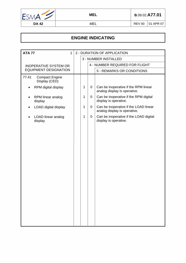
MEL B.09.02.A77.01
DA 42 MEL REV 00 01 APR 07
ENGINE INDICATING
ATA 77 1 2 - DURATION OF APPLICATION
3 - NUMBER INSTALLED
INOPERATIVE SYSTEM OR EQUIPMENT DESIGNATION
00 4 - NUMBER REQUIRED FOR FLIGHT
00 5 - REMARKS OR CONDITIONS
77.41 Compact Engine Display (CED)
RPM digital display 1 0 Can be inoperative if the RPM linear analog display is operative.
RPM linear analog display
1 0 Can be inoperative if the RPM digital display is operative.
LOAD digital display 1 0 Can be inoperative if the LOAD linear analog display is operative.
LOAD linear analog display
1 0 Can be inoperative if the LOAD digital display is operative.

MEL B.09.02.A77.02
DA 42 MEL REV 00 01 APR 07
Associated procedures

MEL B.09.02.A77.03
DA 42 MEL REV 00 01 APR 07
INTENTIONALLY LEFT BLANK


![Boeing Group Assignment for Improvement[Rev03]](https://img.pdfslide.us/doc/110x75/54f9f3c54a7959575b8b45b4/boeing-group-assignment-for-improvementrev03.jpg)