Embed Size (px)
Citation preview
NANOSYSTEM FABRICATION FACILITY (NFF), HKUST
Copyright © 11.2015 by Hong Kong University of Science & Technology. All rights reserved. Page 1
Standard Operating Manual ___________________________________________________________
Cooke Evaporation System

NANOSYSTEM FABRICATION FACILITY (NFF), HKUST
Copyright © 11.2015 by Hong Kong University of Science & Technology. All rights reserved. Page 2
Contents 1. Picture and Location
2. Process Capabilities
2.1 Cleanliness Standard
2.2 Possible Deposition Materials
2.3 Process Specification
2.3.1 What the Cooke Evaporator CAN do
2.3.2 What the Cooke Evaporator CANNOT do
2.4 Sputter Process Useful Information
3. Useful information to work in NFF
3.1 Emergency Responses and Communications
3.2 Become a Qualified Cooke Evaporator User
4 Operating Safety and Rules
4.1 Operation Safety
4.1.1 General Safety
4.1.2 Equipment Safety
4.2 Operation Rules
5. System Operation
5.1 Cooke Evaporator System Description
5.2 Initial Status Checks
5.3 Initial System Checks
5.4 Preparation before Sputtering Process
5.4.1 MDC-360 Thin Film Deposition Controller
5.4.1.1 Operating Displays
5.4.1.2 Operating Controls
5.4.1.3 PARAMETERS/STATUS Displays
5.4.2 TT6 e-beam Power Supply
5.4.2.1 Main Cabinet
5.4.2.2 Control Module
5.4.2.3 Control Module Chassis
5.4.2.4 XY Sweep Controller
5.4.3 Crucible Indexer
5.4.4 Vacuum Controller
5.5 Load and Edit Recipe
5.5.1 Recipe Displays
5.5.1.1 View/Edit Process
5.5.1.2 View/Edit Material
5.5.1.3 View Results
5.5.1.4 Edit System Setup
5.5.2 Starting a Recipe
5.5.3 Trouble, Error and Warning messages
6. Process Run
6.1 Substrate Loading
6.2 Source Material Loading and Crucible Change
6.3 Startup Procedures
7. Process Recording
8. Clean up
9. Check out

NANOSYSTEM FABRICATION FACILITY (NFF), HKUST
Copyright © 11.2015 by Hong Kong University of Science & Technology. All rights reserved. Page 3
Cooke Evaporation System
1. Picture and Location
Fig.1 Cooke Evaporation System
The Cooke Evaporation System is located at NFF Enterprise Center Cleanroom Room4162.
NANOSYSTEM FABRICATION FACILITY (NFF), HKUST
Copyright © 11.2015 by Hong Kong University of Science & Technology. All rights reserved. Page 4
2. Process Capabilities
2.1 Cleanliness Standard
Cooke Evaporation System is classified as NON-STANDARD equipment.
2.2 Possible Deposition Materials
Aluminum
Chromium
Germanium
Gold
Iron
Molybdenum
Nickel
Platinum
Silicon Dioxide
Silver
Titanium
2.3 Process Specification
2.3.1. What the Cooke Evaporator CAN do
Up to 4 pieces 4 inches full silicon in Non-Standard level.
Up to 4 pieces 3 inches full silicon in Non-Standard level.
Up to 12 pieces 2 inches full silicon in Non-Standard level.
Special approval is required for substrate other than 4 inches.
2.3.2. What the Cooke Evaporator CANNOT do
Cooke should not be used for depositing thick films due to time, wear on the system,
expense of materials, and adhesion issues with your sample.
Cooke should not be used to evaporate dielectrics.
Capture all the variability between users in terms of e-beam focusing, source condition
(new sources will have a different deposition rate than a source that has been used many
times).
NANOSYSTEM FABRICATION FACILITY (NFF), HKUST
Copyright © 11.2015 by Hong Kong University of Science & Technology. All rights reserved. Page 5
2.4 Sputter Process Useful Information
To avoid over heat problem of the crucible and power supply, please be reminded individual
sputtering process cannot over 500A per run. Then, a 10 minutes cool down time is required
for every 500A sputtering process. User who fails to follow the rules and cause damage to the
equipment, we will charge you the damaged components, crucible (HKD800) and power
supply (HKD20000).
For aluminum deposition, designated pocket is 2. Deposition rate of 2A/s can be used for
1000A or above, 1A/s can be used for 200~500A, 0.5A/s can be used for less than 200A.
Material density is 2.70gm/cm3, acoustic impedance is 8.17gm/cm
2/s, tooling factor is
100%.
For chromium deposition, designated pocket is 6. Deposition rate of 2A/s can be used for
1000A or above, 1A/s can be used for 200~500A, 0.5A/s can be used for less than 200A.
Material density is 7.20gm/cm3, acoustic impedance is 28.95gm/cm
2/s, tooling factor is
100%.
For germanium deposition, designated pocket is 3. Deposition rate of 2A/s can be used for
1000A or above, 1A/s can be used for 200~500A, 0.5A/s can be used for less than 200A.
Material density is 5.35gm/cm3, acoustic impedance is 17.11gm/cm
2/s, tooling factor is
100%.
For gold deposition, designated pocket is 4. Deposition rate of 2A/s can be used for 1000A
or above, 1A/s can be used for 200~500A, 0.5A/s can be used for less than 200A. Material
density is 19.30gm/cm3, acoustic impedance is 23.18gm/cm
2/s, tooling factor is 100%.
For iron deposition, designated pocket is 2. Deposition rate of 2A/s can be used for 1000A
or above, 1A/s can be used for 200~500A, 0.5A/s can be used for less than 200A. Material
density is 7.86gm/cm3, acoustic impedance is 25.30gm/cm
2/s, tooling factor is 100%.
For molybdenum deposition, designated pocket is 6. Deposition rate of 2A/s can be used
for 1000A or above, 1A/s can be used for 200~500A, 0.5A/s can be used for less than 200A.
Material density is 10.20gm/cm3, acoustic impedance is 34.36gm/cm
2/s, tooling factor is
100%.

NANOSYSTEM FABRICATION FACILITY (NFF), HKUST
Copyright © 11.2015 by Hong Kong University of Science & Technology. All rights reserved. Page 6
For nickel deposition, designated pocket is 6. Deposition rate of 2A/s can be used for
1000A or above, 1A/s can be used for 200~500A, 0.5A/s can be used for less than 200A.
Material density is 8.91gm/cm3, acoustic impedance is 26.68gm/cm
2/s, tooling factor is
27.4%.
For platinum deposition, designated pocket is 5. 0.5A/s or 0.8A/s can be used for less than
300A. Material density is 21.40gm/cm3, acoustic impedance is 36.04gm/cm
2/s, tooling
factor is 100%.
For silicon dioxide deposition, designated pocket is 6. Deposition rate of 2A/s can be used
for 1000A or above, 1A/s can be used for 200~500A, 0.5A/s can be used for less than 200A.
Material density is 2.20gm/cm3, acoustic impedance is 8.25gm/cm
2/s, tooling factor is
100%.
For silver deposition, designated pocket is 1. Deposition rate of 2A/s can be used for 1000A
or above, 1A/s can be used for 200~500A, 0.5A/s can be used for less than 200A. Material
density is 10.50gm/cm3, acoustic impedance is 16.69gm/cm
2/s, tooling factor is 100%.
For titanium deposition, designated pocket is 3. Deposition rate of 2A/s can be used for
1000A or above, 1A/s can be used for 200~500A, 0.5A/s can be used for less than 200A.
Material density is 4.50gm/cm3, acoustic impedance is 14.06gm/cm
2/s, tooling factor is
100%.
Please be reminded film thickness input in the thin film controller is in the unit of 1000A.
For more details information about the process, please consult NFF Enterprise staffs (Peter
PUN or Wilson YIP).
3. Useful information to work in NFF
3.1 Emergency Responses and Communications
In case of emergency issues, please contact NFF staffs,
Peter PUN – Technician (x7225)
Wilson YIP – Senior Technical Officer (x7216)
CK WONG – Senior Technical Officer (x7226)

NANOSYSTEM FABRICATION FACILITY (NFF), HKUST
Copyright © 11.2015 by Hong Kong University of Science & Technology. All rights reserved. Page 7
In case of technical help, please contact NFF staffs,
Peter PUN – Technician (x7225)
Wilson YIP – Senior Technical Officer (x7216)
3.2 Become a Qualified Cooke Evaporator User
Please follow the procedures below to become a qualified user:
Read all materials provided on the NFF website of the Cooke evaporator.
Request Cooke evaporator operation training and examination online.
4. Operating Safety and Rules
4.1. Operation Safety
4.1.1. General Safety
NFF user must familiar themselves with the following general safety issues:
Location of emergency exits and assembly points
Procedures for obtaining first aid assistance must be known.
Various alarm sounds and emergency call procedures must be known.
4.1.2. Equipment Safety
In emergency when using the equipment, push the red emergency button (Fig. 2) to
interrupt the equipment power, and report to the NFF staffs immediately. DO NOT attempt
to resume the equipment on before the problem is solved.
If the equipment fails while being used, never try to fix the problem by your own, please
write down the alarm information and report to NFF sputtering module staffs.
High voltages and hot surfaces are present in this equipment. All users must be properly
qualified, and must not attempt to defeat any equipment interlocks.
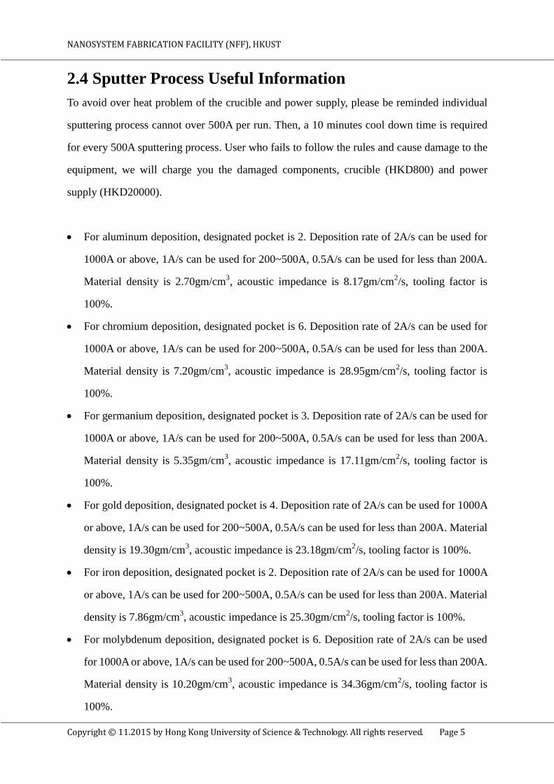
Process alarm or warning message will be displayed at the top right corner of the screen
(Fig. 3). DO NOT attempt to resume the equipment on before the alarm/warning message is
verified.
To avoid any serious injury, please make sure the chamber bolts have been fastened in a
safe position before you raise the chamber.
To avoid any serious injury, please keep person away from the chamber area during

NANOSYSTEM FABRICATION FACILITY (NFF), HKUST
Copyright © 11.2015 by Hong Kong University of Science & Technology. All rights reserved. Page 8
chamber rising.
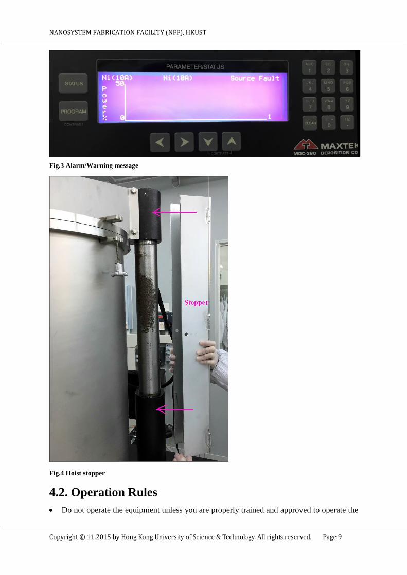
To avoid any malfunction of the hoist system, please insert the hoist stopper during the
source material re-filling. This stopper can stop the sudden falling off of the hook up
chamber (Fig. 4).
To protect your eyes, user must wear the provided goggles to observe the e-beam position
through the viewport (Fig.2).
Fig.2 Emergency button (ESO)
NANOSYSTEM FABRICATION FACILITY (NFF), HKUST
Copyright © 11.2015 by Hong Kong University of Science & Technology. All rights reserved. Page 9
Fig.3 Alarm/Warning message
Fig.4 Hoist stopper
4.2. Operation Rules
Do not operate the equipment unless you are properly trained and approved to operate the

NANOSYSTEM FABRICATION FACILITY (NFF), HKUST
Copyright © 11.2015 by Hong Kong University of Science & Technology. All rights reserved. Page 10
equipment.
Cooke evaporator can be reserved in NFF website.
Please reserve the time slot on your own, and make sure you use your own time slot to do
the sputtering process.
Reservation will be forfeited if user does not show up and check-in within half of the
session time and it may cause a $200 penalty.
Do not leave an on-going etching process unattended.
Please fill all the details of the log-sheet attached, i.e. date, name, project number, email,
project details, material …
Do not change details of the recipe established in the controller. If you need to start a new
material, please consult NFF etching module staffs for help.
Please record all the details of the recipe you used; the memory will be full and need to
release from time to time.
To avoid rapid cooling of the source parts, the process chamber can only be vent at least
half hour after evaporation process.
To avoid over heat problem of the crucible and power supply, individual sputtering process
cannot over 500A per run. Then 10 minutes cool down time is required for another 500A
sputtering process.
To avoid damage the crucible and power supply, the power% is limited to 46%, and the
power will not increase over this limit, otherwise a maximum power alert will be given. To
overcome this problem, user can make fine adjustment to the e-beam position in order to
soak the source at the side of the crucible. To adjust the e-beam position, please read the
following section 5.4.2.4 XY sweep controller, sweep select module, (Fig.15).
To avoid source material over run problem, total film deposition thickness cannot exceed,
5000A for aluminum, 2000A for chromium, 2000A for Titanium, 2000A for Molybdenum,
1500A for Nickel.
To avoid any damage of the hoist system, user must check the vacuum gauge and verify that
the chamber is fully vented (in atmosphere) before activating the hoist.
To avoid too slow or too fast substrate holder rotation, we do not allow user to change the

NANOSYSTEM FABRICATION FACILITY (NFF), HKUST
Copyright © 11.2015 by Hong Kong University of Science & Technology. All rights reserved. Page 11
substrate rotation speed.
To avoid unintended termination of the deposition process, user must check the lifetime of
the crystal is sufficient for the whole deposition process or not; otherwise it may terminate
the process when the crystal life is below 80%. A fresh crystal starts out with a lifetime of
99%. Please see details description of the following MDC-360 controller section.
To avoid unintended contamination of the source material and substrate, make sure there is
no metal film peeling off from the chamber liner, pocket surrounding area, and the substrate
holder. If it happens, please report to the module technicians.
To avoid damage the source, contaminate the system or eventually leads water leak, please
do not operate a source on an empty pocket or with the beam impacting some portion of the
surrounding structure.
5. System Operation
5.1 Cooke Evaporator System Description
The Cooke evaporation system is a semi-automatic electron beam thin film deposition tool,
and equipped with a CTI cryo-pump, it capable of sustained a 10-7
torr high vacuum.
Basically, the system consists of, 1) vacuum chamber, 2) pumping system, 3) control system,
4) electron-beam power supplies. Brief descriptions of individuals are as follow:
1. Vacuum Chamber
The vacuum chamber is a cylindrical stainless steel bell-jar, 20” ID x 30” high, with a
removable top-plate, and a viewport is located in the center of the chamber. In order to
load/unload the substrates or source material, there is a hoist actuator can be used to lift the
top plate or the whole chamber. The chamber has two attachment screws for connecting the
process chamber to the top plate for whole chamber lifting. In addition, a set of chamber
liners are inserted, and can be removed for routine cleaning. In order to get a better
uniformity and step coverage, the system is also equipped with a rotating substrate holding
plate.
2. Pumping system
The pumping system is a programmable controller with output to provide automated control

NANOSYSTEM FABRICATION FACILITY (NFF), HKUST
Copyright © 11.2015 by Hong Kong University of Science & Technology. All rights reserved. Page 12
of all vacuum related components. The program allows automated startup, pump down,
venting, and shutdown.
3. Control system
The Maxtek MDC-360 controller offers full capability of view/edit source material or
deposition recipes, with the crucible indexer which controls the pocket rotation, this
eventually provides automatic control of single or multi-layer deposition.
4. E-beam power supplies
The e-beam power supplies include main AC main cabinet, high voltage control module, XY
sweep controller, and the crucible indexer. These units used to maintain the e-beam and
control its position.
5.2 Initial Status Checks
Please check the status of Cooke evaporator shutdown notice posted in the NFF reservation
website.
If the equipment has been reserved, you can check the name and project number that
displayed in NFF reservation website are correct.
Please check-in the reserved equipment on your own within half of the session time. To do
the check-in, please scan your NFF access card over the card reader attached.
If you failed to check in the machine, there is an interlock, and you cannot operate the
equipment normally.
Before operate the equipment, make sure you have read and ready to fill the details of the
log-sheets attached.
5.3 Initial System Checks
There are several interlocks used to monitor the whole system for safe operation, please
check and make sure the following interlocks of TT6 controller are fulfilled before using the
system (Fig. 5):
VACUUM INTERLOCK: minimum vacuum level (3x10⁻⁶
Torr) must be present before
high voltage is energized, to prevent danger operation of high voltage and high current

NANOSYSTEM FABRICATION FACILITY (NFF), HKUST
Copyright © 11.2015 by Hong Kong University of Science & Technology. All rights reserved. Page 13
power supply when the chamber is at low vacuum or even at atmosphere pressure.
WATER FLOW INTERLOCK: water cooling that protects the cryo pump, sputter gun, and
the rate monitor head from damage due to over-heat.
DOORS: interlock on all doors and panels that permit high voltage access are closed, and
then the interlock will be satisfied.
ZERO: interlock insures that the emission control is at its minimum position before high
voltage and filament voltage can be applied to the source.
READY: when all the interlocks are closed, this indicator will be energized. The OFF push
button LED will also energize at this moment.
Fig. 5 System interlocks LEDs of the TT6 Control
5.4 Preparation before Sputtering Process
Prior to the system operation, please read the description of film deposition controller,
e-beam power supply, crucible indexer and vacuum controller.
5.4.1 MDC-360 Thin Film Deposition Controller
Typically, if evaporation rate is a function of source power alone, a rate controller would not
be necessary. One would establish the power required achieving the desired rate by set the
power at that point; this control system is called “open loop” control.

NANOSYSTEM FABRICATION FACILITY (NFF), HKUST
Copyright © 11.2015 by Hong Kong University of Science & Technology. All rights reserved. Page 14
Unfortunately, evaporation rate is a function of many variables. For E-gun sources, rate is
affected by material level, water cooling temperature, beam position, sweep pattern, etc.
Therefore, if we want to achieve a known and constant rate, then we need a rate controller.
The MDC-360 rate controller compares the measured rate with the desired rate and attempts
to keep them equal by adjusting the power level of the power supply, and this is a “close
loop” feedback control. It utilizes three control loop parameters referred to as PID parameters;
Proportional gain, Integral Time constant and Derivative Time constant to provide
optimization to the control loop. However, all these parameters have been set and no further
adjustment required by the user.
Front panel display and operation The MDC-360 thin film controller mainly consists of
Operating displays, Operating Controls, Parameters/Status displays and user keypads (Fig.6).
Fig.6a Schematic MDC-360 thin film controller
Fig.6b Real MDC-360 thin film controller
5.4.1.1 Operating Displays
There are six parameters can be viewed in the operating display, Rate, Power, Thickness,
Layer number, Crystal Health %, and Time to go. Users are required to check those
parameters from time to time during deposition process.
Rate Å/sec: it displays the deposition rate in angstroms per second. Typically, the
deposition rates set in the recipes are in the range of 0.5A/s – 2A/s.
Power %: it displays a percent of power to maintain the deposition rate described above.
Typically, we set the maximum power is about 45% of the full power.

NANOSYSTEM FABRICATION FACILITY (NFF), HKUST
Copyright © 11.2015 by Hong Kong University of Science & Technology. All rights reserved. Page 15
Thickness: it displays the measured thickness in KÅ.
Layer Number: it displays the layer number of the current process.
Crystal Health %: it displays the health percentage of the sensor crystal in use. A fresh
crystal starts out with a health of 99%. Typical useful sensor lifetime is around 80%.
Time to go: time remaining to be completed.
5.4.1.2 Operating Controls
There are six operating keys under the operating displays, Manual, Start, Abort, Reset,
Zero, and Shutter, each key is equipped with LED to indicate the controller’s status.
Manual: this key is used to toggle the MDC-360 manual mode on and off. A red light
behind the key indicates the controller is in manual power control mode. However, we do
not allow user to operate the power control in manual mode.
Start: this key starts a process, a green light behind the key indicate the controller is in
process. When this key is pressed the first time, then a list of stored recipe is displayed in
the right sided PARAMETER/STATUS screen. Then, move cursor to select the desire
recipe, and press “START” key again to start the process. Note that operating messages
will be displayed in the PARAMETERS/STATUS screen.
Abort: to stop a running process, click the “ABORT” key into the abort mode. All source
powers are set to zero, and discrete output from the MDC-360 controller is set to inactive
status.
Reset: the “RESET” key is used to clear the controller from the Abort mode and back into
a Ready mode. A yellow light behind the key indicate a READY mode.
Zero: the “ZERO” key is active at all the times to calibrate the thickness display to go zero.
Fail to set the controller zero will results a film thicker than that desired and displayed.
Therefore, user is not allowed to operate this key.
Shutter: the “SHUTTER” key is use to open and close the shutter manually. The red light
is illuminated when the shutter is closed. However, user is not allowed to operate this key.
5.4.1.3 PARAMETERS/STATUS Displays
Once power on the MDC-360 controller, a Sign-On screen will be displayed (Fig.7), and user

NANOSYSTEM FABRICATION FACILITY (NFF), HKUST
Copyright © 11.2015 by Hong Kong University of Science & Technology. All rights reserved. Page 16
can press any key to put the controller into the IDLE mode. Then, a RESET key can be used
to put the controller further into the READY mode. After pressing the RESET key, then the
Parameters/Status screen will return to the display function being used at the last power off.
Fig.7 Sign-on screen
Left sided of the PARAMETERS/STATUS display, there are STATUS and PROGRAM
keys; it uses to display the status information and program information.
STATUS displays
There are six different run time status screens that can be displayed at any time by pressing
the STATUS key, part of the graphs that user concern will be shown as follows:
Fig.8a Rate vs Time graph
Fig.8b Thickness vs Time graph

NANOSYSTEM FABRICATION FACILITY (NFF), HKUST
Copyright © 11.2015 by Hong Kong University of Science & Technology. All rights reserved. Page 17
Fig.8c Power vs Time graph
5.4.2 TT6 e-beam Power Supply
The TT-6 Electron beam Power supply consists of 1) Main cabinet, and 2) Control
Module/Sweep module, as shown (Fig.9)
Fig. 9 TT-6 e-beam power supply
5.4.2.1 Main Cabinet
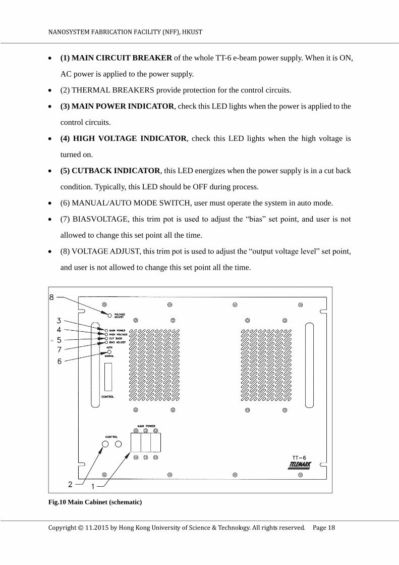
Details of the main cabinet (Fig.10) are illustrated as follows; and user must pay attention to
the items written in bold:
NANOSYSTEM FABRICATION FACILITY (NFF), HKUST
Copyright © 11.2015 by Hong Kong University of Science & Technology. All rights reserved. Page 18
(1) MAIN CIRCUIT BREAKER of the whole TT-6 e-beam power supply. When it is ON,
AC power is applied to the power supply.
(2) THERMAL BREAKERS provide protection for the control circuits.
(3) MAIN POWER INDICATOR, check this LED lights when the power is applied to the
control circuits.
(4) HIGH VOLTAGE INDICATOR, check this LED lights when the high voltage is
turned on.
(5) CUTBACK INDICATOR, this LED energizes when the power supply is in a cut back
condition. Typically, this LED should be OFF during process.
(6) MANUAL/AUTO MODE SWITCH, user must operate the system in auto mode.
(7) BIASVOLTAGE, this trim pot is used to adjust the “bias” set point, and user is not
allowed to change this set point all the time.
(8) VOLTAGE ADJUST, this trim pot is used to adjust the “output voltage level” set point,
and user is not allowed to change this set point all the time.
Fig.10 Main Cabinet (schematic)

NANOSYSTEM FABRICATION FACILITY (NFF), HKUST
Copyright © 11.2015 by Hong Kong University of Science & Technology. All rights reserved. Page 19
5.4.2.2 Control Module
Details of the control module (Fig.11) are illustrated as follows, and user must pay attention
to the items written in bold:
(1) HIGH VOLTAGE/EMISSION, OFF, the on/off function is provided by a pair of
push-buttons on the panel. The off button lights when the High Voltage and the Emission
are off.
(2) HIGH VOLTAGE/EMISSION, ON, the on button lights when the High Voltage and
the Emission are on.
(3) ZERO, this interlock insures that the emission control is at its minimum position before
high voltage and filament voltage can be applied to the source. The LED will energize
when the interlock is fulfilled.
(4) WATER, this interlock assures that there is sufficient water flow to cool the source. The
LED will energize when the interlock is closed.
(5) DOORS, this interlocks on all doors and panels that permit high voltage access are
closed, then the interlock is closed.
(6) VACUUM, the minimum vacuum level set must be present before high voltage can be
energized
(7) READY, when all the interlocks are closed, this indicator will be energized. The OFF
push button LED will also energize at this moment.
(8) VOLTAGE/CURRENT METER, a digital bar graph displays the output voltage and a
digital display shows the emission current. The voltage range of indication is 0 to 10kV and
the current is 0 to 0.999 ampere. Typical value of voltage/current is about 7.5KV and 0.25A
(Fig. 5).
(9) EMISSION CURRENT, adjustment of the emission level of the electron beam source,
and user is not allowed to change this setting.

NANOSYSTEM FABRICATION FACILITY (NFF), HKUST
Copyright © 11.2015 by Hong Kong University of Science & Technology. All rights reserved. Page 20
Fig.11 Control module of TT6
5.4.2.3 Control Module Chassis
Details of the control module chassis (Fig.12) are illustrated as follows:
(1) ON/OFF SWITCH, this provides sweeper power, not TT6 controller power. In our
system, it is always set to be ON.
(2) MODE (CONTROL/SWEEP SELECT) SWITCH, selects between Control and Sweep
Select. In our system, we set SWEEP Select mode instead of Sweep Control mode.
(3) POSITION LEDs, it shows the relative position of the beam in the pocket, lateral axis
(left & right).
(4) POSITION LEDs, it shows the relative position of the beam in the pocket, longitudinal
axis (near & far).
Fig.12a Control module chassis (schematic)

NANOSYSTEM FABRICATION FACILITY (NFF), HKUST
Copyright © 11.2015 by Hong Kong University of Science & Technology. All rights reserved. Page 21
Fig.12b Control module chassis (real)
5.4.2.4 XY Sweep Controller
XY sweep controller includes i) Sweep control module (Fig.13) and ii) Sweep select module
(Fig.14). However, we recommend user adjust the e-beam sweep in manually, so sweep select
module will be focused.
i) Sweep Control Module mainly control the beam sweeping by joy stick
Fig. 13 Sweep Control module
(1) PATTERN MODE SWITCH, this 3 position mode switch is used to select between

NANOSYSTEM FABRICATION FACILITY (NFF), HKUST
Copyright © 11.2015 by Hong Kong University of Science & Technology. All rights reserved. Page 22
SPIRAL, MANUAL beam position and TRIANGLE pattern. With SPIRAL mode, the
longitudinal/modulation frequency knob controls the spiral-collapse frequency, while both
lateral and longitudinal amplitude knobs control the overall size. Then the joystick can be
used to position the beam. The Modulation Amp knob controls the depth of spiraling
collapse. With TRIANGLE mode, the lateral and longitudinal amplitudes and frequencies
of the beam are set with the corresponding knobs. The joystick can be used to position the
beam, and the resulting beam movement is in a diamond pattern. With MANUAL mode,
the joystick can be used to position the beam, there is no sweeping. In this system, we are
running in MANUAL mode, user is strictly prohibited to change the setting.
(2) JOYSTICK, it moves the beam or center position of the patterns.
(3) & (4) AMPLITUDE, it adjusts the overall pattern size.
(5) & (6). FREQUENCY, it adjusts the sweeping speeds.
(7) MOD AMP, it adjusts the depth of the spiral’s collapse
ii) Sweep Select Module control the beam by using the knobs instead of joystick.
Fig.14 Sweep Select module
(1) MANUAL/AUTO SWITCH, to change the control of the Sweep Select module from
front panel to the remote input. In this system, we are running in MANUAL mode.
(2) SELECT PATTERN, to select the active pattern for manual mode. In this system, we are
using Sweep pattern 1.

NANOSYSTEM FABRICATION FACILITY (NFF), HKUST
Copyright © 11.2015 by Hong Kong University of Science & Technology. All rights reserved. Page 23
(3) ACTIVE PATTERN LED, it indicates which one of the four patterns is active.
(4) PATTERN MODE SWITCH, to select between SPIRAL, TRIANGLE, and MANUAL
mode of operation. In this system, we are running in MANUAL mode.
(5) & (6) POSITION, turn these 2 knobs to adjust the beam or the center position of
the patterns. However, make sure you know where the e-beam is pointing at before make
any adjustment. Also, please make fine adjustment only.
(7) & (8) AMPLITUDE, it adjusts the overall pattern size
(9) & (10) FREQUENCY, it adjusts the sweeping speed.
(11) MOD AMP, it adjusts the depth of the spiral’s collapse.
5.4.3 Crucible Indexer
The Telemark 376 indexer (Fig. 15), positions the crucibles from one of the sources; it also
has a position-indicating function. The controller features crucible pocket selection lights to
tell the operator which crucible is in the “evaporate” position. However, it should be run in
AUTO mode. In the Cooke evaporation system, it equipped with 4 pockets for different kind
of materials. Typically, pocket 1 to 4, contains Nickel crucible, Molybdenum crucible,
Aluminum crucible, Chromium crucible/Titanium crucible respectively. For titanium and
chromium source, it shares the same pocket 4, so user must check and change the crucible if
necessary.
Fig.15 Crucible indexer
5.4.4 Vacuum Controller
The HSD vacuum controller is a five modes switch, and we will describe the mode of
operation that useful to the user in the following (Fig.16):
PUMP mode, it evacuates the chamber from atm. to high vacuum. Firstly, the mechanical
pump will be turned on, and then the roughing valve will open to evacuate the chamber

NANOSYSTEM FABRICATION FACILITY (NFF), HKUST
Copyright © 11.2015 by Hong Kong University of Science & Technology. All rights reserved. Page 24
until high-set-point reached. Then, roughing valve will be closed, and the high vacuum
valve will be open. Once high vacuum pumping has commenced, the ion gauge will be on,
and the system will remain in this mode during deposition.
VENT mode, it brings the chamber from high vacuum to atm. Firstly, the high vacuum
valve will be close, and then vent valve will be open. However, the vent valve will remain
in open position even when the chamber is completely vented. To conserve the vent gas,
when venting is completed, turn the dial to START-UP mode, then the vent valve will close
while the system will remain in stand-by situation.
Fig. 16 HSD vacuum controller
5.5 Load and Edit Recipe
User is required to check, and set the recipe before deposition. To view or edit the recipe,
please read the following:
5.5.1 Recipe Displays
If a PROGRAM key is pressed, then a Main Menu will be displayed as follow (Fig.17):
Fig.17 Main Menu
In this Menu, View/Edit Process, View/Edit Material, View Result and Edit System Setup are
displayed. User can move the cursor to the position to select the desire function.
NANOSYSTEM FABRICATION FACILITY (NFF), HKUST
Copyright © 11.2015 by Hong Kong University of Science & Technology. All rights reserved. Page 25
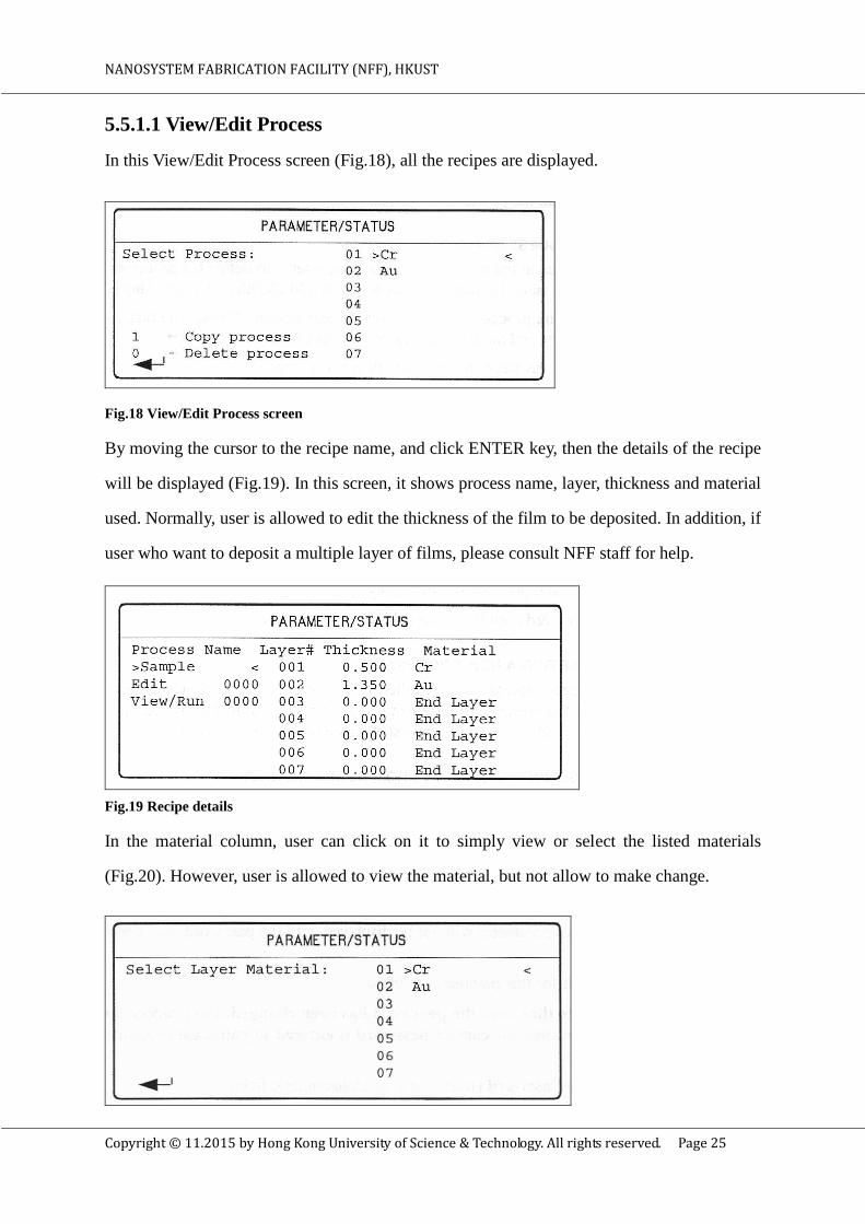
5.5.1.1 View/Edit Process
In this View/Edit Process screen (Fig.18), all the recipes are displayed.
Fig.18 View/Edit Process screen
By moving the cursor to the recipe name, and click ENTER key, then the details of the recipe
will be displayed (Fig.19). In this screen, it shows process name, layer, thickness and material
used. Normally, user is allowed to edit the thickness of the film to be deposited. In addition, if
user who want to deposit a multiple layer of films, please consult NFF staff for help.
Fig.19 Recipe details
In the material column, user can click on it to simply view or select the listed materials
(Fig.20). However, user is allowed to view the material, but not allow to make change.
NANOSYSTEM FABRICATION FACILITY (NFF), HKUST
Copyright © 11.2015 by Hong Kong University of Science & Technology. All rights reserved. Page 26
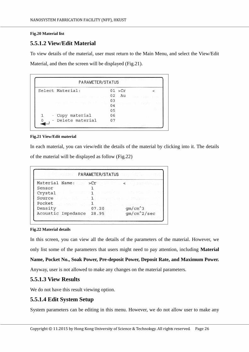
Fig.20 Material list
5.5.1.2 View/Edit Material
To view details of the material, user must return to the Main Menu, and select the View/Edit
Material, and then the screen will be displayed (Fig.21).
Fig.21 View/Edit material
In each material, you can view/edit the details of the material by clicking into it. The details
of the material will be displayed as follow (Fig.22)
Fig.22 Material details
In this screen, you can view all the details of the parameters of the material. However, we
only list some of the parameters that users might need to pay attention, including Material
Name, Pocket No., Soak Power, Pre-deposit Power, Deposit Rate, and Maximum Power.
Anyway, user is not allowed to make any changes on the material parameters.
5.5.1.3 View Results
We do not have this result viewing option.
5.5.1.4 Edit System Setup
System parameters can be editing in this menu. However, we do not allow user to make any

NANOSYSTEM FABRICATION FACILITY (NFF), HKUST
Copyright © 11.2015 by Hong Kong University of Science & Technology. All rights reserved. Page 27
changes on this system setup menu, so we will not go in details.
5.5.2 Starting a Recipe
To start a recipe, please make sure you have read the following procedures of MDC-360
controller to start a recipe:
In READY mode, to start a recipe by clicking the “START” key, and then the Run Process
Selection Screen will be shown (Fig.20).
Fig.23 Run Process Screen
Then, select the process recipe by positioning the cursor on the desired process recipe
name.
Finally, to actually start the process, press the START key again, then the controller will
scan the total process definition and the condition of the system, and the process will start if
everything appears to be in order.
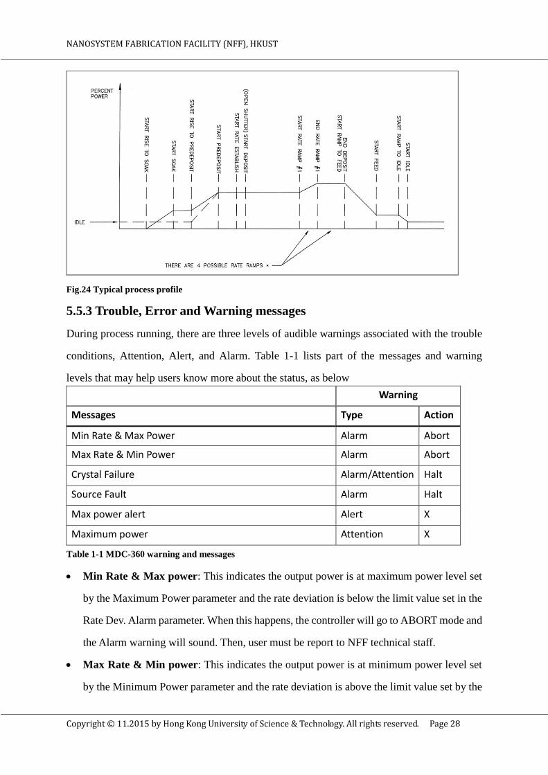
A typical process profile is shown below for reference (Fig. 24).
NANOSYSTEM FABRICATION FACILITY (NFF), HKUST
Copyright © 11.2015 by Hong Kong University of Science & Technology. All rights reserved. Page 28
Fig.24 Typical process profile
5.5.3 Trouble, Error and Warning messages
During process running, there are three levels of audible warnings associated with the trouble
conditions, Attention, Alert, and Alarm. Table 1-1 lists part of the messages and warning
levels that may help users know more about the status, as below
Warning
Messages Type Action
Min Rate & Max Power Alarm Abort
Max Rate & Min Power Alarm Abort
Crystal Failure Alarm/Attention Halt
Source Fault Alarm Halt
Max power alert Alert X
Maximum power Attention X
Table 1-1 MDC-360 warning and messages
Min Rate & Max power: This indicates the output power is at maximum power level set
by the Maximum Power parameter and the rate deviation is below the limit value set in the
Rate Dev. Alarm parameter. When this happens, the controller will go to ABORT mode and
the Alarm warning will sound. Then, user must be report to NFF technical staff.
Max Rate & Min power: This indicates the output power is at minimum power level set
by the Minimum Power parameter and the rate deviation is above the limit value set by the

NANOSYSTEM FABRICATION FACILITY (NFF), HKUST
Copyright © 11.2015 by Hong Kong University of Science & Technology. All rights reserved. Page 29
Rate Dev. Alarm parameter. When this happens, the controller will go to ABORT mode and
the Alarm warning will sound. Then, user must be report to NFF technical staff.
Crystal Failure: This indicates lack of a valid signal from the sensor, and generally results
from a failed crystal but may also indicate problems in the crystal mounting or
interconnection between the sensor and the controller.
Source Fault: This indicates that the correct source pocket position feedback has not been
achieved within the time set by the Rotator Delay parameter.
Max Power Alert: This indicates that the power output level has been at the Maximum
Power level longer than the time period set in the Power Alert Delay parameter.
Maximum Power: This indicates that the output power is at or below the minimum power
set by the Minimum Power parameter.
6. Process RunTo run a process, please read the following instructions below:
6.1 Substrate Loading
To load substrates into the chamber, please follow the procedures below:
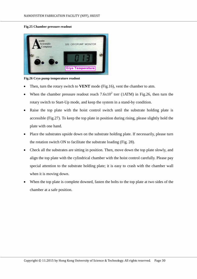
Typical the system is idle in a high vacuum condition; please check i) pressure readout
(Fig.25), and ii) cryo temperature (Fig. 26). If the chamber base pressure is over 1x10⁻⁵
torr
or cryo temperature is over 23(K), please report to NFF module staffs. To view the
chamber/cryo pressure readout, click the gauge ON button once.
NANOSYSTEM FABRICATION FACILITY (NFF), HKUST
Copyright © 11.2015 by Hong Kong University of Science & Technology. All rights reserved. Page 30
Fig.25 Chamber pressure readout
Fig.26 Cryo pump temperature readout
Then, turn the rotary switch to VENT mode (Fig.16), vent the chamber to atm.
When the chamber pressure readout reach 7.6x10² torr (1ATM) in Fig.26, then turn the
rotary switch to Start-Up mode, and keep the system in a stand-by condition.
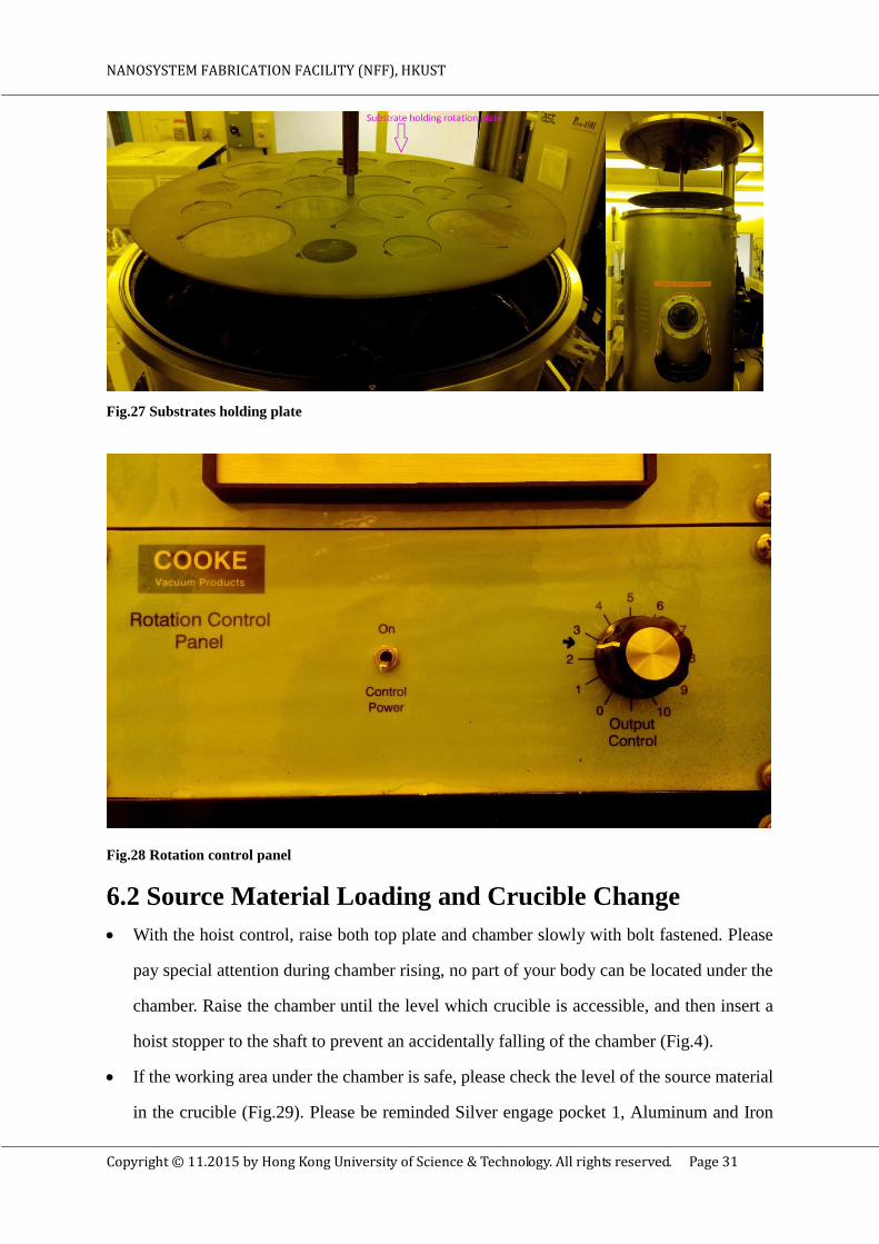
Raise the top plate with the hoist control switch until the substrate holding plate is
accessible (Fig.27). To keep the top plate in position during rising, please slightly hold the
plate with one hand.
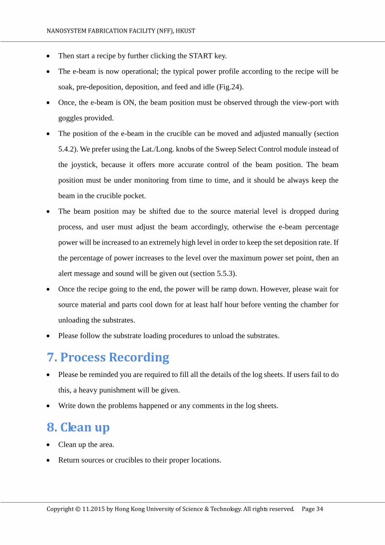
Place the substrates upside down on the substrate holding plate. If necessarily, please turn
the rotation switch ON to facilitate the substrate loading (Fig. 28).
Check all the substrates are sitting in position. Then, move down the top plate slowly, and
align the top plate with the cylindrical chamber with the hoist control carefully. Please pay
special attention to the substrate holding plate; it is easy to crash with the chamber wall
when it is moving down.
When the top plate is complete downed, fasten the bolts to the top plate at two sides of the
chamber at a safe position.
NANOSYSTEM FABRICATION FACILITY (NFF), HKUST
Copyright © 11.2015 by Hong Kong University of Science & Technology. All rights reserved. Page 31
Fig.27 Substrates holding plate
Fig.28 Rotation control panel
6.2 Source Material Loading and Crucible Change
With the hoist control, raise both top plate and chamber slowly with bolt fastened. Please
pay special attention during chamber rising, no part of your body can be located under the
chamber. Raise the chamber until the level which crucible is accessible, and then insert a
hoist stopper to the shaft to prevent an accidentally falling of the chamber (Fig.4).
If the working area under the chamber is safe, please check the level of the source material
in the crucible (Fig.29). Please be reminded Silver engage pocket 1, Aluminum and Iron

NANOSYSTEM FABRICATION FACILITY (NFF), HKUST
Copyright © 11.2015 by Hong Kong University of Science & Technology. All rights reserved. Page 32
share the same pocket 2, Titanium and Germanium share the same pocket 3, Gold engage
pocket 4, Platimun engage pocket 5, and Chromium, Molybdenum, Nickel, Silicon
Dioxide share the same pocket 6. User is not allowed to swap the designated pocket
material to avoid cross material contamination.
Fig.29 e-beam source, rotation pocket, and crucible
Add source material pieces if necessary. However, do not put too many pieces in the
crucible to prevent it from blocking the pocket rotation. In case user needs to change
crucible of source material, use a tweezers to pull it out from the pocket slowly.
All the sources and crucibles are located in the plastic box left hand sided of the chamber.
Check the film monitor crystal lifetime is enough for the process (section 5.4.1.1),
otherwise report to NFF module staffs for replacement.
Visually check any film peeling problem inside the chamber, and report to NFF staff if it
happens.
If everything is in position, then remove the hoist stopper. Please make sure the stopper has
been removed before moving to the next step, otherwise it will damage the hoist system.
Slowly turn down both top plate and chamber with the hoist control, and slightly hold the

NANOSYSTEM FABRICATION FACILITY (NFF), HKUST
Copyright © 11.2015 by Hong Kong University of Science & Technology. All rights reserved. Page 33
chamber wall with one hand to keep it in position.
When the whole chamber is completely sit on the platform table, turn the rotary switch to
PUMP mode, this starts an automatic pumping sequence.
Wait the high vacuum pressure until it reaches at least 5x10⁻⁶
Torr, and it takes more than
one hour.
Change the material name plate if necessary.
Power on the substrate rotation (Fig.28) but user is not allowed to change the rotation
speed.
6.3 Startup Procedures
The system is now ready for deposition. Before moving to the next step, please make sure
you read the operation of the thin film controller, and e-beam source power supply/XY sweep
module (section 5.4 & 5.5).
Turn on the MAXTEK MDC-360 deposition controller. View the recipe listed in the
View/Edit PROCESS menu, and selects a recipe using the “arrow” and “enter” keys, then
moves the cursor to the Thickness column, and set the required thickness. The measuring
unit of the film thickness is in 1000A. Finally, check in the Material column, the right
material is selected (Fig.18).
Once, the recipe is ready, turn on the AC power circuit breaker of the Main cabinet (Fig.10).
However, please wait two minutes for the unit to warm up before proceeding.
Check interlocks status on the panel of TT-3/6 controller are all satisfied (Fig.5).
Turn ON the power of the crucible indexer, and it must be set to AUTO mode for operation.
Turn on the high voltage and emission by depressing the Control Module’s
Voltage/Emission ON push-button (Fig.11). Be careful, mis-operation of the power supply
result in costly damage and lethal voltages are present.
High voltage will then applied to the electron beam source and HV level will be indicated
by the HV Voltage digital bar graph (Fig.5).
Select a recipe in the MDC-360 thin film controller by clicking the START key as
described in the section 5.5.
NANOSYSTEM FABRICATION FACILITY (NFF), HKUST
Copyright © 11.2015 by Hong Kong University of Science & Technology. All rights reserved. Page 34
Then start a recipe by further clicking the START key.
The e-beam is now operational; the typical power profile according to the recipe will be
soak, pre-deposition, deposition, and feed and idle (Fig.24).
Once, the e-beam is ON, the beam position must be observed through the view-port with
goggles provided.
The position of the e-beam in the crucible can be moved and adjusted manually (section
5.4.2). We prefer using the Lat./Long. knobs of the Sweep Select Control module instead of
the joystick, because it offers more accurate control of the beam position. The beam
position must be under monitoring from time to time, and it should be always keep the
beam in the crucible pocket.
The beam position may be shifted due to the source material level is dropped during
process, and user must adjust the beam accordingly, otherwise the e-beam percentage
power will be increased to an extremely high level in order to keep the set deposition rate. If
the percentage of power increases to the level over the maximum power set point, then an
alert message and sound will be given out (section 5.5.3).
Once the recipe going to the end, the power will be ramp down. However, please wait for
source material and parts cool down for at least half hour before venting the chamber for
unloading the substrates.
Please follow the substrate loading procedures to unload the substrates.
7. Process Recording Please be reminded you are required to fill all the details of the log sheets. If users fail to do
this, a heavy punishment will be given.
Write down the problems happened or any comments in the log sheets.
8. Clean up Clean up the area.
Return sources or crucibles to their proper locations.

NANOSYSTEM FABRICATION FACILITY (NFF), HKUST
Copyright © 11.2015 by Hong Kong University of Science & Technology. All rights reserved. Page 35
9. Check outCheck out the equipment immediately after use.