Embed Size (px)
Citation preview

Stand-alone instruments forWAVE Bioreactor 2/10 and20/50Operating Instructions
cytiva.com

Table of Contents
1 Introduction ........................................................................................................ 51.1 Important user information ....................................................................................................................... 61.2 WAVE system configurations ................................................................................................................... 81.3 Stand-alone instruments ............................................................................................................................ 101.4 Control software ............................................................................................................................................ 111.5 Literature .......................................................................................................................................................... 12
2 Safety instructions ............................................................................................. 132.1 Safety precautions ........................................................................................................................................ 142.2 Labels and symbols ....................................................................................................................................... 172.3 Emergency procedures ............................................................................................................................... 18
3 Common process controllers ............................................................................ 193.1 Functions .......................................................................................................................................................... 203.2 Process controller on stand-alone instruments ................................................................................ 223.3 Changing Process controller parameters ............................................................................................ 23
3.3.1 Large Process controller ............................................................................................................................ 243.3.2 Small Process controller ............................................................................................................................ 26
4 DOOPT20 dissolved oxygen monitor ................................................................ 274.1 Introduction/view .......................................................................................................................................... 284.2 Installation ........................................................................................................................................................ 30
4.2.1 Site requirements ......................................................................................................................................... 314.2.2 Unpacking ....................................................................................................................................................... 324.2.3 Installation ....................................................................................................................................................... 334.2.4 Spare parts and accessories .................................................................................................................... 34
4.3 Operation .......................................................................................................................................................... 354.4 Maintenance .................................................................................................................................................... 37
4.4.1 Maintenance frequency ............................................................................................................................ 384.4.2 Cleaning ........................................................................................................................................................... 394.4.3 Calibration ....................................................................................................................................................... 404.4.4 DOOPT probe maintenance and storage ........................................................................................... 434.4.5 Instrument repair ......................................................................................................................................... 45
4.5 Troubleshooting ............................................................................................................................................. 46
5 CO2MIX20 CO2/air controller ........................................................................... 485.1 Introduction/view ......................................................................................................................................... 49
5.1.1 CO2 leakage .................................................................................................................................................... 515.2 Installation ........................................................................................................................................................ 52
5.2.1 Site requirements ......................................................................................................................................... 535.2.2 Unpacking ....................................................................................................................................................... 545.2.3 Installation ....................................................................................................................................................... 555.2.4 Spare parts and accessories .................................................................................................................... 56
5.3 Operation .......................................................................................................................................................... 575.4 Maintenance .................................................................................................................................................... 59
5.4.1 Maintenance frequency ............................................................................................................................ 605.4.2 Cleaning ........................................................................................................................................................... 615.4.3 Calibration ....................................................................................................................................................... 62
Table of Contents
2 Stand-alone instruments for WAVE Bioreactor 2/10 and 20/50 Operating Instructions 87450009 AD

5.4.4 Instrument repair ......................................................................................................................................... 635.5 Troubleshooting ............................................................................................................................................. 64
6 CO2MIX20-R CO2/air controller ........................................................................ 666.1 Introduction/view .......................................................................................................................................... 67
6.1.1 CO2 leakage .................................................................................................................................................... 696.2 Installation ........................................................................................................................................................ 70
6.2.1 Site requirements ......................................................................................................................................... 716.2.2 Unpacking ....................................................................................................................................................... 726.2.3 Installation ....................................................................................................................................................... 736.2.4 Spare parts and accessories .................................................................................................................... 74
6.3 Operation .......................................................................................................................................................... 756.4 Maintenance .................................................................................................................................................... 76
6.4.1 Maintenance frequency ............................................................................................................................ 776.4.2 Cleaning ........................................................................................................................................................... 786.4.3 Calibration ....................................................................................................................................................... 796.4.4 Instrument repair ......................................................................................................................................... 80
6.5 Troubleshooting ............................................................................................................................................. 81
7 O2MIX20 O2/air controller ................................................................................ 837.1 Introduction/view .......................................................................................................................................... 847.2 Installation ........................................................................................................................................................ 85
7.2.1 Site requirements ......................................................................................................................................... 867.2.2 Unpacking ....................................................................................................................................................... 877.2.3 Installation ....................................................................................................................................................... 887.2.4 Spare parts and accessories .................................................................................................................... 89
7.3 Operation .......................................................................................................................................................... 907.4 Maintenance .................................................................................................................................................... 92
7.4.1 Maintenance frequency ............................................................................................................................ 937.4.2 Cleaning ........................................................................................................................................................... 947.4.3 Calibration ....................................................................................................................................................... 957.4.4 Instrument repair ......................................................................................................................................... 96
7.5 Troubleshooting ............................................................................................................................................. 97
8 O2MIX20-R O₂/air controller ............................................................................. 988.1 Introduction/view .......................................................................................................................................... 998.2 Installation ........................................................................................................................................................ 100
8.2.1 Site requirements ......................................................................................................................................... 1018.2.2 Unpacking ....................................................................................................................................................... 1028.2.3 Installation ....................................................................................................................................................... 1038.2.4 Spare parts and accessories .................................................................................................................... 104
8.3 Operation .......................................................................................................................................................... 1058.4 Maintenance .................................................................................................................................................... 106
8.4.1 Maintenance frequency ............................................................................................................................ 1078.4.2 Cleaning ........................................................................................................................................................... 1088.4.3 Calibration ....................................................................................................................................................... 1098.4.4 Instrument repair ......................................................................................................................................... 110
8.5 Troubleshooting ............................................................................................................................................. 111
9 PUMP20 peristaltic feed/harvest or acid/base pump ..................................... 1129.1 Introduction/view .......................................................................................................................................... 1139.2 Installation ........................................................................................................................................................ 114
Table of Contents
Stand-alone instruments for WAVE Bioreactor 2/10 and 20/50 Operating Instructions 87450009 AD 3

9.2.1 Site requirements ......................................................................................................................................... 1159.2.2 Unpacking ....................................................................................................................................................... 1169.2.3 Installation ....................................................................................................................................................... 1179.2.4 Spare parts and accessories .................................................................................................................... 119
9.3 Operation .......................................................................................................................................................... 1209.4 Maintenance .................................................................................................................................................... 121
9.4.1 Maintenance frequency ............................................................................................................................ 1229.4.2 Cleaning ........................................................................................................................................................... 1239.4.3 Pumphead tensioning ................................................................................................................................ 1249.4.4 Instrument repair ......................................................................................................................................... 125
9.5 Troubleshooting ............................................................................................................................................. 126
10 Reference information ....................................................................................... 12710.1 Specifications .................................................................................................................................................. 12810.2 Recycling information .................................................................................................................................. 13010.3 Regulatory information ............................................................................................................................... 131
10.3.1 Contact information .................................................................................................................................... 13210.3.2 European Union and European Economic Area .............................................................................. 13310.3.3 Regulations for North America ............................................................................................................... 13410.3.4 Regulatory statements .............................................................................................................................. 135
10.4 Ordering information ................................................................................................................................... 136
Appendix A: Communications and data acquisition .............................................. 137A.1 Overview ............................................................................................................................................................ 138A.2 Analog/Alarm port ......................................................................................................................................... 139A.3 Analog signals ................................................................................................................................................. 140A.4 Alarm contact .................................................................................................................................................. 141A.5 Digital communication protocol .............................................................................................................. 142A.6 Communication wiring ................................................................................................................................ 143A.7 Digital instrument addressing .................................................................................................................. 145
Appendix B: DOOPT20 measurement theory .......................................................... 146B.1 Introduction ..................................................................................................................................................... 147B.2 Measurement theory ................................................................................................................................... 148B.3 Effect of temperature ................................................................................................................................... 150B.4 Measurement range ..................................................................................................................................... 151B.5 Cross-sensitivity ............................................................................................................................................ 152B.6 Response time ................................................................................................................................................ 153
B.6.1 Bare probe ....................................................................................................................................................... 154B.6.2 Wet Oxywell2 ................................................................................................................................................. 155B.6.3 Dry Oxywell2 .................................................................................................................................................. 156
B.7 Stability .............................................................................................................................................................. 157
Table of Contents
4 Stand-alone instruments for WAVE Bioreactor 2/10 and 20/50 Operating Instructions 87450009 AD

1 Introduction
Purpose of the manualThis manual provide you with the instructions needed to handle WAVE Bioreactor™system optional stand-alone instruments. For further information regarding the use ofWAVE Bioreactor 2/10, WAVE Bioreactor 20/50 and WAVEPOD II1, refer to WAVEBioreactor System BASE 2/10 EH Operating Instructions and WAVE Bioreactor 20/50and WAVEPOD II User Manual, respectively.
PrerequisitesIn order to operate WAVE Bioreactor stand-alone instruments safely and according tothe intended purpose the following prerequisites must be met:
• You should be acquainted with the use of general laboratory equipment and withhandling of biological materials.
• You must read the Safety Instructions in Chapter 2 Safety instructions, on page 13.
• The system should be installed according to the Installation sections in Chapter 4DOOPT20 dissolved oxygen monitor, on page 27 to Chapter 9 PUMP20 peristalticfeed/harvest or acid/base pump, on page 112.
In this chapterThis chapter contains important user information and a general description of WAVEBioreactor stand-alone instruments, and their intended use.
In this chapter
Section See page
1.1 Important user information 6
1.2 WAVE system configurations 8
1.3 Stand-alone instruments 10
1.4 Control software 11
1.5 Literature 12
1 The optional WAVEPOD II controller integrates instrumentation associated with WAVEBioreactor units. This includes pH, dissolved oxygen, and CO2/O2 gas mixing controls.
1 Introduction
Stand-alone instruments for WAVE Bioreactor 2/10 and 20/50 Operating Instructions 87450009 AD 5

1.1 Important user information
Read this before operating theproduct
All users must read the entire Operating Instructions before installing, oper-ating or maintaining the product.
Always keep the Operating Instructions at hand when operating the product.
Do not install, operate, or perform maintenance on the product in any other way thandescribed in the user documentation. If you do, you may be exposed or expose othersto hazards that can lead to personal injury and you may cause damage to the equip-ment.
Intended useThe WAVE Bioreactor system is intended to be used as development and manufac-turing equipment for expansion of cells. Cultivation is performed in a single use,gamma irradiated bag, known as a Cellbag™, which is placed on the WAVE Bioreactorinstrument.
Note: When used for cell therapy applications outside the European Union andAustralia, the WAVE Bioreactor system shall be used for research only.
Control of various parameters can be made in different ways depending on WAVEBioreactor system configuration. Optional stand-alone instruments can be used tocontrol, for example, O2 concentration and CO2 concentration.
DefinitionsThis user documentation contains safety notices (WARNING, CAUTION, and NOTICE)concerning the safe use of the product. See definitions below.
WARNING
WARNING indicates a hazardous situation which, if not avoided,could result in death or serious injury. It is important not to proceeduntil all stated conditions are met and clearly understood.
1 Introduction1.1 Important user information
6 Stand-alone instruments for WAVE Bioreactor 2/10 and 20/50 Operating Instructions 87450009 AD
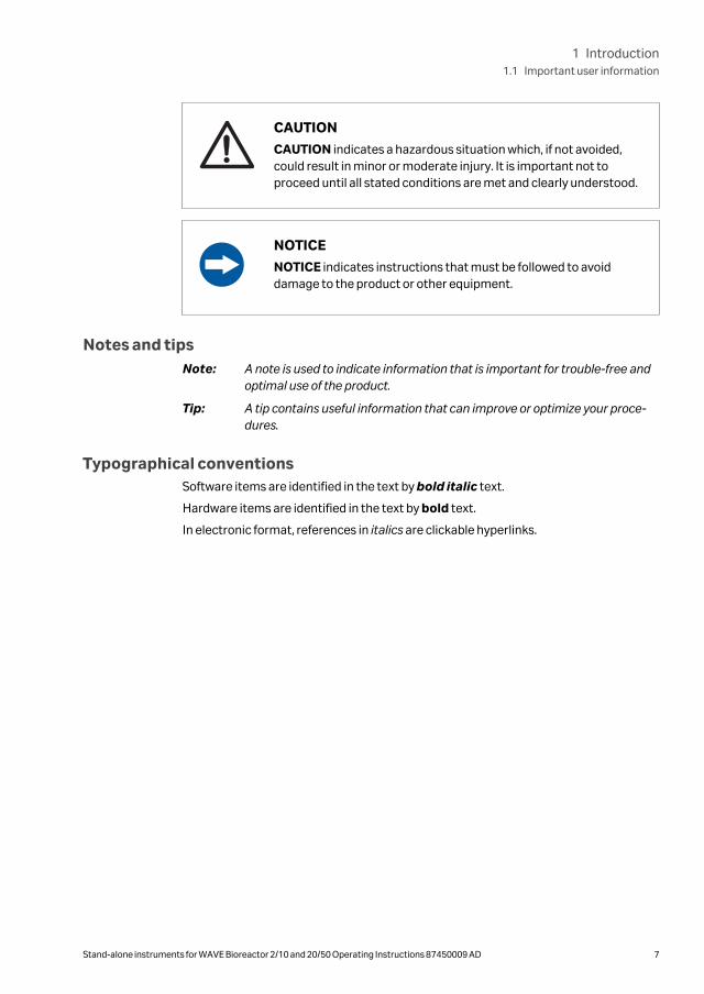
CAUTION
CAUTION indicates a hazardous situation which, if not avoided,could result in minor or moderate injury. It is important not toproceed until all stated conditions are met and clearly understood.
NOTICE
NOTICE indicates instructions that must be followed to avoiddamage to the product or other equipment.
Notes and tipsNote: A note is used to indicate information that is important for trouble-free and
optimal use of the product.
Tip: A tip contains useful information that can improve or optimize your proce-dures.
Typographical conventionsSoftware items are identified in the text by bold italic text.
Hardware items are identified in the text by bold text.
In electronic format, references in italics are clickable hyperlinks.
1 Introduction1.1 Important user information
Stand-alone instruments for WAVE Bioreactor 2/10 and 20/50 Operating Instructions 87450009 AD 7

1.2 WAVE system configurationsThere are several different sizes of WAVE™ systems available that provide scalable cellculturing possibilities and several different configurations available for control of keyculture parameters:
• WAVE Bioreactor instrument options with different internal control modules.
• WAVEPOD II options with different internal control modules (available for WAVEBioreactor 20/50 instrument).
• Stand-alone instruments for control of specific parameters (described in thismanual).
For examples of how control of different parameters can be achieved, see Table 1.1, onpage 9. Note that more than one stand-alone instrument can be used with a WAVEBioreactor instrument to get access to more control functions.
For some parameters, several control options are available. For example, pH in theculture medium can be controlled by:
• On-line control of pH by pH measurement and pH adjustment by acid and baseadditions. This requires a WAVEPOD II with pH control module and PUMP20.
• Indirect control of pH by changing the CO2 concentration setpoint. This requires:
- Integrated CO2 control module (as in BASE20/50EHT-CO2), or
- WAVEPOD II with CO2 control module, or
- the stand-alone instrument CO2MIX20 or CO2MIX20-R.
Table 1.1, on page 9 shows example instrument and system configurations. Thestand-alone instrument PERFCONT2E and all WAVEPOD II units are included, but notdescribed further in this manual. See the respective product manuals for more infor-mation.
1 Introduction1.2 WAVE system configurations
8 Stand-alone instruments for WAVE Bioreactor 2/10 and 20/50 Operating Instructions 87450009 AD

Table 1.1: Examples of WAVE Bioreactor 2/10 and 20/50 system configurations using WAVE
Bioreactor instruments alone or in combination with stand-alone instruments. Several other
options are possible. Some configurations of WAVE Bioreactor 20/50 system are available as Dual
system configuration (WAVE Bioreactor instrument 20/50 EHTD), which enables operation of two
Cellbag bioreactors in parallel.
System configuration Control parameters
Bioreactor
base unit
Stand-alone
instrument Ro
ckin
g
Tem
per
atu
re
Dis
solv
ed O
2
pH
Inle
t gas
CO
2 co
nce
ntr
atio
n
Inle
t gas
O2
con
cen
trat
ion
Per
fusi
on
cult
ure
WAVE Bioreactor 2/10 system
BASE2/10EH + +
BASE2/10EH DOOPT20 + + +
BASE2/10EH CO2MIX20 + + +
BASE2/10EH O2MIX20 + + +
BASE2/10EH PERFCONT2E + + +
WAVE Bioreactor 20/50 system
BASE20/50EHT + +
BASE20/50EHT-CO2 + + +
BASE20/50EHT-O2 + + +
BASE20/50EHT-L PUMP20 + + +
BASE20/50EHT DOOPT20 + + +
BASE20/50EHT CO2MIX20 + + +
BASE20/50EHT O2MIX20 + + +
BASE20/50EHT WAVEPOD II PHOPTCO2
+ + + +
BASE20/50EHT WAVEPOD II DOOPTO2
+ + + +
BASE20/50EHT WAVEPOD II PHOPTDOOPT CO2 O2
+ + + + + +
BASE20/50EHT-L WAVEPOD II PHOPTDOOPT CO2 O2PUMP20
+ + + + + + +
1 Introduction1.2 WAVE system configurations
Stand-alone instruments for WAVE Bioreactor 2/10 and 20/50 Operating Instructions 87450009 AD 9

1.3 Stand-alone instruments
OverviewSeveral stand-alone instruments for the WAVE Bioreactor 2/10 and 20/50 systems areavailable. The stand-alone instruments are used connected to the WAVE Bioreactorinstrument and designed to fit in racks (SRACK) for single instruments. Racks include apower supply and a RS485 dataport communicating via the MODBUS RTU protocol fordata acquisition.
The available stand-alone instruments are listed in the table below. See respectivechapter for a description and instruction for use.
Name Function Chapter
DOOPT20 Dissolved oxygenmonitor
Chapter 4 DOOPT20dissolved oxygenmonitor, on page 27
CO2MIX20 CO2/air controller Chapter 5 CO2MIX20CO2/air controller, onpage 48
CO2MIX20-R CO2/air controller (rota-meter model)
Chapter 6 CO2MIX20-RCO2/air controller, onpage 66
O2MIX20 O2/air controller Chapter 7 O2MIX20O2/air controller, on page83
O2MIX20-R O2/air controller (rota-meter model)
Chapter 8 O2MIX20-RO₂/air controller, on page98
PUMP20 Peristaltic feed/harvestor acid/base pump
Chapter 9 PUMP20 peri-staltic feed/harvest oracid/base pump, on page112
1 Introduction1.3 Stand-alone instruments
10 Stand-alone instruments for WAVE Bioreactor 2/10 and 20/50 Operating Instructions 87450009 AD

1.4 Control softwareThe WAVE system stand-alone instruments are equipped with embedded software forcontrol and supervision. See Chapter 3 Common process controllers, on page 19 forinstruction for use of common process controllers.
1 Introduction1.4 Control software
Stand-alone instruments for WAVE Bioreactor 2/10 and 20/50 Operating Instructions 87450009 AD 11

1.5 LiteratureFor further information regarding the use of WAVE Bioreactor 2/10, WAVE Bioreactor20/50 and WAVEPOD II refer to the following:
• WAVE Bioreactor System BASE 2/10 EH Operating Instructions, article no.87450023.
• WAVE Bioreactor System 20/50 and WAVEPOD II User Manual, article no.28984680.
1 Introduction1.5 Literature
12 Stand-alone instruments for WAVE Bioreactor 2/10 and 20/50 Operating Instructions 87450009 AD

2 Safety instructions
This chapter describes safety compliance, safety labels, general safety precautions,emergency procedures, power failure and recycling of WAVE stand-alone instruments.
In this chapter
Section See page
2.1 Safety precautions 14
2.2 Labels and symbols 17
2.3 Emergency procedures 18
2 Safety instructions
Stand-alone instruments for WAVE Bioreactor 2/10 and 20/50 Operating Instructions 87450009 AD 13

2.1 Safety precautions
IntroductionBefore installing, operating or maintaining stand-alone instruments, you must beaware of the hazards described in WAVE Bioreactor System BASE 2/10 EH OperatingInstructions and WAVE Bioreactor System 20/50EHT Operating Instructions, as well ashazards specifically related to WAVE stand-alone instruments, which are described inthis manual. Follow the instructions provided to avoid personal injury or damage to theequipment.
The safety precautions in this section are grouped into the following categories:
• General precautions
• Personal protection
• Installing
• System operation
• Maintenance
General precautions
WARNINGDo not use any accessories not supplied or recommended byCytiva.
Personal protection
WARNINGHazardous substances. When using hazardous chemical andbiological agents, take all suitable protective measures, such aswearing protective glasses and gloves resistant to the substancesused. Follow local and/or national regulations for safe operationand maintenance of the system.
2 Safety instructions2.1 Safety precautions
14 Stand-alone instruments for WAVE Bioreactor 2/10 and 20/50 Operating Instructions 87450009 AD

Installing instrument
WARNINGPlace CO2MIX20 and CO2MIX20-R instruments in a wellventilated environment. Failure to do so can lead to heightenedCO2 concentrations.
Care should be taken to remove pressurized CO2 supply when notin use.
WARNINGPlace O2MIX20 and O2MIX20-R instruments in a well venti-lated environment. Failure to do so can lead to heightened O2
concentrations.
Care should be taken to remove pressurized O2 supply when not inuse.
WARNINGProtective ground. The WAVE stand-alone instruments mustalways be connected to grounded power outlets.
WARNINGSupply voltage. Ensure that the supply voltage at the wall outletcorresponds to the marking on the instrument before connectingthe power cord.
CAUTIONEnsure that all tubing, hoses and cables are placed so that the riskor tripping accidents is minimized.
System operation
CAUTIONRemove any spillage on the floor immediately to minimize the riskfor slipping accidents.
2 Safety instructions2.1 Safety precautions
Stand-alone instruments for WAVE Bioreactor 2/10 and 20/50 Operating Instructions 87450009 AD 15

Maintenance
WARNINGElectrical shock hazard. All repairs should be done by servicepersonnel authorized by Cytiva. Do not open any covers or replaceparts unless specifically stated in the user documentation.
WARNINGDisconnect power. Always disconnect power from the instru-ment before performing any maintenance task.
WARNINGOnly spare parts that are approved or supplied by Cytiva may beused for maintaining or servicing the system.
2 Safety instructions2.1 Safety precautions
16 Stand-alone instruments for WAVE Bioreactor 2/10 and 20/50 Operating Instructions 87450009 AD

2.2 Labels and symbols
IntroductionThis section describes the product nameplate (label) and other safety and regulatorylabels attached to the product.
System labelThe system label is located on the back of the equipment. The system label identifiesthe equipment and shows electrical data, regulatory compliance, and warningsymbols.
Symbols used in safety labels
Label Description
Warning! Read the user documentation before usingthe system. Do not open any covers or replace partsunless specifically stated in the user documentation.
2 Safety instructions2.2 Labels and symbols
Stand-alone instruments for WAVE Bioreactor 2/10 and 20/50 Operating Instructions 87450009 AD 17
2.3 Emergency proceduresThis section describes how to do an emergency shutdown of a WAVE instrument. Thesection also describes the result in the event of power failure.
Emergency procedures
In an emergency situation, do as follows to stop the run:
Step Action
1 Switch off the power to the instrument by pressing the power switch to the Oposition.
2 Disconnect the power cord from the power outlet.
2 Safety instructions2.3 Emergency procedures
18 Stand-alone instruments for WAVE Bioreactor 2/10 and 20/50 Operating Instructions 87450009 AD

3 Common process controllers
In this chapter
Section See page
3.1 Functions 20
3.2 Process controller on stand-alone instruments 22
3.3 Changing Process controller parameters 23
3 Common process controllers
Stand-alone instruments for WAVE Bioreactor 2/10 and 20/50 Operating Instructions 87450009 AD 19

3.1 FunctionsMost WAVE Bioreactor stand-alone instruments are controlled by use of integratedProcess controllers. In the stand-alone instrument, the Process controller (large orsmall type) is integrated in the front of the instrument, see the example figure below.
Figure 3.1: Example of stand-alone instrument (DOOPT20) with a small Processcontroller, see arrow.
The Process controllers are used in similar way in different stand-alone instrumentsand the main functionality is described in this chapter. Actual and setpoint values canbe viewed and setpoint values can be changed.
Figure 3.2: Large Process controller (left) and small Process controller (right).
3 Common process controllers3.1 Functions
20 Stand-alone instruments for WAVE Bioreactor 2/10 and 20/50 Operating Instructions 87450009 AD

Controller item Function
• 1, 2, 3, 4 (Large controller)
• 1, 2 (Small controller)
Output indicators light when corre-sponding output is activated.
% Auto/manual indicator lights whencorresponding output is activated
Upper display: red digits Shows process value or parametervalue
Lower display: green digits Shows setpoint or parameter name.
Advance buttonPress to display through menu items orparameters
Up arrow button Press to increase setpoint or parameter
Down arrow button Press to decrease setpoint or param-eter
∞Home button Press to return to normal operation
3 Common process controllers3.1 Functions
Stand-alone instruments for WAVE Bioreactor 2/10 and 20/50 Operating Instructions 87450009 AD 21

3.2 Process controller on stand-alone instruments
Table 3.1: Stand-alone instruments with large and small Process controller
Large Process controller Small Process controller
O2MIX20, O₂/air controller DOOPT20, dissolved oxygen monitor
O2MIX20-R, O₂/air controller O2MIX20, O2/air controller
CO2MIX20, CO₂/air controller CO2MIX20, CO2/air controller
O2MIX20-R, O₂/air controller
CO2MIX20-R, CO₂/air controller
3 Common process controllers3.2 Process controller on stand-alone instruments
22 Stand-alone instruments for WAVE Bioreactor 2/10 and 20/50 Operating Instructions 87450009 AD

3.3 Changing Process controller parameters
CAUTIONThe Process controllers are factory set for optimum performance.Changes to any parameters should only be attempted by qualifiedpersonnel. Please consult Cytiva for assistance.
In this section
Section See page
3.3.1 Large Process controller 24
3.3.2 Small Process controller 26
Changing the setpoint value
Change the setpoint by following the procedure below. This procedure is the same forall controller sizes.
Step Action
1 Increase the setpoint value as desired by pressing the button.
2 Decrease the setpoint value as desired by pressing the button.
3 Common process controllers3.3 Changing Process controller parameters
Stand-alone instruments for WAVE Bioreactor 2/10 and 20/50 Operating Instructions 87450009 AD 23

3.3.1 Large Process controller
Unlocking the controller
To avoid accidental changes, all Process controller parameters are locked. Unlock theProcess controller by following the procedure.
Step Action
1Press and hold down the and ∞ buttons for 10 seconds to enter theCUST (customize) menu. This puts the controller into the Fcty (factory)display (shown in green in the lower display).
Note:Displays may appear slightly different.
2 Press the button to get the LOC menu (in red in the upper display).
3 While in the display Fcty and the menu LOC, set the following parameters tochng:
• sp
• cust
• ope
• set
• cal
For each parameter, set the value to chng by pressing the button. If thevalue chng is unavailable, set the value READ instead. Select a new param-
eter by pressing the button.
4 The Process Controller is now unlocked. Press the ∞ button to exit.
3 Common process controllers3.3 Changing Process controller parameters
3.3.1 Large Process controller
24 Stand-alone instruments for WAVE Bioreactor 2/10 and 20/50 Operating Instructions 87450009 AD

Changing addresses for standaloneinstruments
To change the MODBUS network address on the CO2MIX20 and the O2MIX20 instru-ments, follow the procedure below.
Step Action
1 Press the and buttons together for 10 seconds until INPUT set isdisplayed.
2 Press the button until Out 4 Set is displayed.
3Press the button until Addr is shown in green on the lower display. Theupper display indicated the address number.
4 Press either the or buttons to change the address.
5 Press the ∞ button to save and exit.
Changing the baud rate for stand-alone instruments
To change the baud rate on the CO2MIX20 and the O2MIX20 instruments.
Step Action
1 Press the and buttons together for 10 seconds until INPUT set isdisplayed.
2 Press the button until Out 4 Set is displayed.
3Press the button until baud is shown in green on the lower display. Theupper display indicated the address number.
4 Press either the or buttons to change the baud rate. Available baudrates are: 1200, 2400, 4800, 9600 and 19.2k.
(The default baud rate is 9600)
5 Press the ∞ button to save and exit.
3 Common process controllers3.3 Changing Process controller parameters
3.3.1 Large Process controller
Stand-alone instruments for WAVE Bioreactor 2/10 and 20/50 Operating Instructions 87450009 AD 25

3.3.2 Small Process controller
Changing addresses for standaloneinstruments
To change the MODBUS network address on the DOOPT20 and Air Controllers.
Step Action
1 Press and hold down the and buttons for 3 seconds. SET page isdisplayed.
2Press the button repeatedly until ADDR is shown in green.
3 Press either the or buttons to change the address.
4 Press the ∞ button to save.
Changing the baud rate for stand-alone instruments
To change the baud rate on the DOOPT20 and Air Controllers.
Step Action
1 Press and hold down the and buttons for 3 seconds. SET page isdisplayed.
2Press the button repeatedly until BAUD is shown in green.
3 Press either the or buttons to change the baud rate. Baud rates of9600, 19.2 and 38.4 are available.
(The default baud rate is 9600)
4 Press the ∞ button to save.
3 Common process controllers3.3 Changing Process controller parameters
3.3.2 Small Process controller
26 Stand-alone instruments for WAVE Bioreactor 2/10 and 20/50 Operating Instructions 87450009 AD

4 DOOPT20 dissolved oxygen monitor
In this chapter
Section See page
4.1 Introduction/view 28
4.2 Installation 30
4.3 Operation 35
4.4 Maintenance 37
4.5 Troubleshooting 46
4 DOOPT20 dissolved oxygen monitor
Stand-alone instruments for WAVE Bioreactor 2/10 and 20/50 Operating Instructions 87450009 AD 27

4.1 Introduction/viewThe DOOPT20 stand-alone instrument provides amplification, display, and data trans-mission of the dissolved oxygen concentration. It allows the real-time measurement ofdissolved oxygen concentration inside the Cellbag bioreactors. The illustration belowshows the location of the main parts of DOOPT20.
1
2
3
54
6
9
8
7
Part Description
1 Processcontroller
2 LCD display
3 Probeconnector
Part Description
4 TEMP COMPcontrol
5 PUSH FORMENUbutton
6 DataportConnectors
Part Description
7 Analogoutputconnector
8 Power switch,on (I), off (O)
9 PowerReceptacle
DOOPT probesThe DOOPT20 stand-alone instrument can be connected to a DOOPT probe, which isused to monitor dissolved oxygen (DO) levels in cell cultures. A special fiber optic DOmicrosensor is used inside a sealed silicone Oxywell 2 sleeve. This allows the probe tobe inserted and removed without compromising sterility. DOOPT-PROBEs may bereused for many months until photo bleaching causes low signal amplitude and theprobe becomes progressively too noisy for accurate measurements.
The silicone sleeve is made of FDA approved Class VI plastic and is the only contactsurface. This eliminates any concern about toxicity of the sensing dye or leaching of thedye into the culture fluid.
4 DOOPT20 dissolved oxygen monitor4.1 Introduction/view
28 Stand-alone instruments for WAVE Bioreactor 2/10 and 20/50 Operating Instructions 87450009 AD

Cellbag
DOOPT probe
bioreactor
Oxywell2 sleeve
For more information, see Appendix B DOOPT20 measurement theory, on page 146.
4 DOOPT20 dissolved oxygen monitor4.1 Introduction/view
Stand-alone instruments for WAVE Bioreactor 2/10 and 20/50 Operating Instructions 87450009 AD 29

4.2 Installation
In this section
Section See page
4.2.1 Site requirements 31
4.2.2 Unpacking 32
4.2.3 Installation 33
4.2.4 Spare parts and accessories 34
4 DOOPT20 dissolved oxygen monitor4.2 Installation
30 Stand-alone instruments for WAVE Bioreactor 2/10 and 20/50 Operating Instructions 87450009 AD

4.2.1 Site requirements
Parameter Requirement
Electrical power 24 V DC through adapter
(110 to 120 V~ or
220 to 240 V~, 50/60 Hz)
Placement Stable laboratory bench
Operating temperature 4°C to 40°C
Humidity <95%, non-condensing
4 DOOPT20 dissolved oxygen monitor4.2 Installation
4.2.1 Site requirements
Stand-alone instruments for WAVE Bioreactor 2/10 and 20/50 Operating Instructions 87450009 AD 31

4.2.2 UnpackingUnpack the equipment.
Please check the packing list to see that all items on the list are included. If any partsare missing, contact your Cytiva representative.
Place the equipment on a stable surface.
Check the equipment for any apparent damage before starting installation. Documentany damage carefully and contact your Cytiva representative.
4 DOOPT20 dissolved oxygen monitor4.2 Installation
4.2.2 Unpacking
32 Stand-alone instruments for WAVE Bioreactor 2/10 and 20/50 Operating Instructions 87450009 AD

4.2.3 Installation
Step Action
1 Make sure that the DOOPT monitor is powered off.
2 Connect the transformer to a grounded power outlet.
3 Connect the transformer to the power inlet of monitor. The power connectoris located on the rear of the instrument.
4 Remove the DOOPT probe from its packaging. The tip can be left in itsprotective tube until a calibration of the probe is needed.
5 Connect the DOOPT probe to the PROBE connector located on the frontpanel of the monitor. Make sure that the small ridge on the plug is lined upwith the notch on the connector. Push the plug in and twist to lock it in posi-tion.
4 DOOPT20 dissolved oxygen monitor4.2 Installation
4.2.3 Installation
Stand-alone instruments for WAVE Bioreactor 2/10 and 20/50 Operating Instructions 87450009 AD 33

4.2.4 Spare parts and accessoriesFor correct up to date information on spare parts and accessories, see the web addresson the back cover or contact your local Cytiva representative.
4 DOOPT20 dissolved oxygen monitor4.2 Installation
4.2.4 Spare parts and accessories
34 Stand-alone instruments for WAVE Bioreactor 2/10 and 20/50 Operating Instructions 87450009 AD

4.3 OperationControl of DOOPT20 dissolved oxygen monitor
See Section 4.1 Introduction/view, on page 28 for location of buttons and Chapter 3Common process controllers, on page 19 for description of Process controller.
NOTICEWhen inserted into the Oxywell2 sheath, the probe has a longerresponse time due to diffusion through the silicone rubbermembrane. The response time in the Oxywell2 is greatly improvedby filling the tip with liquid such as distilled water or saline.
NOTICESensitive DOOPT probe. Do not touch the tip of the probe withyour finger or any object. Do not attempt to clean or dry the tip witha cloth. Gently wave the DOOPT probe back and forth to air-dry it.
Step Action
1 Connect the probe to the connector on the front panel. Make sure that thesmall ridge on the plug is lined up with the notch on the connector. Push theplug in and twist to lock it in position, do not force the plug.
2 Turn the power switch on (I). The power switch is located on the back of thestand-alone instrument.
3 The displays should light up and a version number is displayed on the LCDdisplay.
4 Within a few seconds, the LCD display shows T= temperature compensationvalue and A = amplitude.
Note:When the A -value is less than 5000, the DOOPT Probe has approximately 3to 4 weeks of use left. Replace the probe immediately if A -value is under2000.
5 After a period of 15 seconds, the display indicates the temperature in °C andP = phase angle of the DOOPT probe. The phase angle and amplitudedisplays alternate every 15 seconds.
6 The Process control shows the dissolved oxygen value (red).
Note:Please wait while the unit scans the probe.
4 DOOPT20 dissolved oxygen monitor4.3 Operation
Stand-alone instruments for WAVE Bioreactor 2/10 and 20/50 Operating Instructions 87450009 AD 35

Step Action
7 Calibrate the DOOPT probe before use, see Section 4.4.3 Calibration, on page40 for instructions.
8 Insert the DOOPT probe in the Cellbag bioreactor.
Note:The DOOPT probe can be removed and reinserted repeatedly without anydanger of contamination.
a. Locate the Oxywell2 fitting on the Cellbag bioreactor.
Oxywell2fitting
b. Remove the luer cap from the fitting.
c. Fill the Oxywells with liquid using the fill kit provided with the DOOPTprobe. Instructions are included with the probe. The water is critical toprovide a response time (designated t90 in control software) of about 3to 5 minutes. Using the DOOPT in air will prolong the time considerably.
d. Insert the DOOPT probe carefully into the Oxywell2.
e. Secure the DOOPT probe by gently tightening the luer connector.
9 For some applications, calibration of the probe after insertion into the bag isdesired (this is possible if the Cellbag bioreactor has not yet been inocu-lated). With aeration and rocking this should correspond to the 100% satu-ration point.
10 Let the Cellbag bioreactor equilibrate so that the medium is at the correcttemperature and at 100% air saturation.
11 Set the manual temperature compensation to the temperature of theCellbag bioreactor and recalibrate the 100% point, as described in Section4.4.3 Calibration, on page 40.
4 DOOPT20 dissolved oxygen monitor4.3 Operation
36 Stand-alone instruments for WAVE Bioreactor 2/10 and 20/50 Operating Instructions 87450009 AD

4.4 Maintenance
In this section
Section See page
4.4.1 Maintenance frequency 38
4.4.2 Cleaning 39
4.4.3 Calibration 40
4.4.4 DOOPT probe maintenance and storage 43
4.4.5 Instrument repair 45
4 DOOPT20 dissolved oxygen monitor4.4 Maintenance
Stand-alone instruments for WAVE Bioreactor 2/10 and 20/50 Operating Instructions 87450009 AD 37
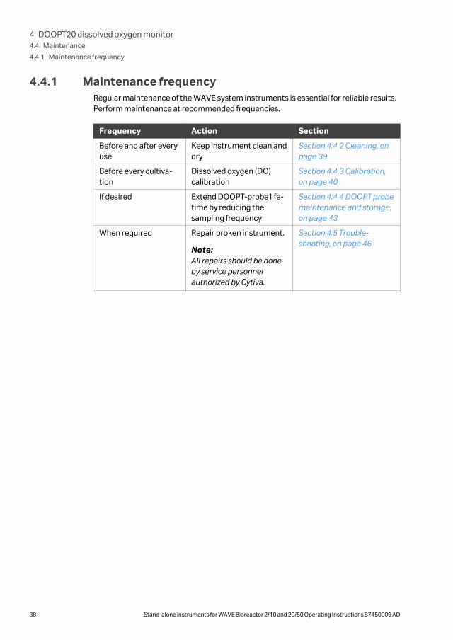
4.4.1 Maintenance frequencyRegular maintenance of the WAVE system instruments is essential for reliable results.Perform maintenance at recommended frequencies.
Frequency Action Section
Before and after everyuse
Keep instrument clean anddry
Section 4.4.2 Cleaning, onpage 39
Before every cultiva-tion
Dissolved oxygen (DO)calibration
Section 4.4.3 Calibration,on page 40
If desired Extend DOOPT-probe life-time by reducing thesampling frequency
Section 4.4.4 DOOPT probemaintenance and storage,on page 43
When required Repair broken instrument.
Note:All repairs should be doneby service personnelauthorized by Cytiva.
Section 4.5 Trouble-shooting, on page 46
4 DOOPT20 dissolved oxygen monitor4.4 Maintenance
4.4.1 Maintenance frequency
38 Stand-alone instruments for WAVE Bioreactor 2/10 and 20/50 Operating Instructions 87450009 AD

4.4.2 CleaningKeep the instruments dry and clean. The instruments must be turned off andunplugged before cleaning begins. Clean the exterior of the instruments with a dampcloth with water and, if required, alcohol. Do not use abrasive cleaners. Water shouldnot be applied directly to the instruments. Make sure that the instruments arecompletely dry before plugging them in.
4 DOOPT20 dissolved oxygen monitor4.4 Maintenance
4.4.2 Cleaning
Stand-alone instruments for WAVE Bioreactor 2/10 and 20/50 Operating Instructions 87450009 AD 39
4.4.3 CalibrationThe DOOPT probe should be calibrated before starting cultivation.
DO calibration
Calibration of the DOOPT probe is performed using a two-point calibration method. Setthe zero oxygen and 100% air saturation level, respectively, according to the instruc-tions below.
Note: The DOOPT instrument compensates for sensor temperature variations andsolubility effects. However, probe calibrations should be performed at thesame temperature as the process measurement when possible.
Preparations
Step Action
1 Power up the instrument.
2 Connect the DOOPT probe to the PROBE connector on DOOPT20.
3 Open a new packet of zero oxygen calibration solution (ZERO OXYSOLN).Immerse the probe tip in the solution and wait for the reading to stabilize.
Note:Nitrogen gas (N2) may be used instead of ZERO OXYSOLN for the zero oxygencalibration.
4 Check the temperature compensation and adjust as necessary.
5 Set the zero oxygen and 100% air saturation level, respectively, according tothe instructions below.
Zero oxygen calibration using DOOPT20
Follow the instruction below to perform a zero oxygen calibration using DOOPT20.
Note: Replace the probe If the calibration error is 10% or larger.
Step Action
1 Press the PUSH FOR MENU button.
Result:The display shows --MENU-- 1.CALIB.
2 Press the PUSH FOR MENU button.
Result:The display shows SET ZERO →NO
3 Turn the PUSH FOR MENU button to change NO to YES.
4 DOOPT20 dissolved oxygen monitor4.4 Maintenance
4.4.3 Calibration
40 Stand-alone instruments for WAVE Bioreactor 2/10 and 20/50 Operating Instructions 87450009 AD

Step Action
4 Press the PUSH FOR MENU button.
Result:The display shows PUSH2SET P=54.95ª. (54.95ª is an example of thephase angle. The numerical value shown can be slightly different).
5 When the phase angle reading is stable (within ±0.25ª), press the PUSH FORMENU button.
Result: The display shows TRY0 0 (no of scans), 000.00% (actual reading). Ifthe display shows NEED 0% CAL, re-calibration is needed.
100% oxygen calibration using DOOPT20
Follow the instruction below to perform a 100% air saturation calibration usingDOOPT20.
Step Action
1 Check the temperature compensation and adjust as necessary.
2 Remove the probe from the zero oxygen solution. Rinse the probe in waterand shake dry. Allow the probe to equilibrate in air. Do not touch the probetip or attempt to dry it with a cloth.
3 When the reading is stable (within ±2%) in 1 to 2 minutes, press the PUSHFOR MENU button.
Result:The display shows --MENU-- 1.CALIB.
4 Press the PUSH FOR MENU button. twice
Result:The display shows SET 100 % → NO.
5 Turn the PUSH FOR MENU button to change NO to YES.
6 Press the PUSH FOR MENU button.
Result:The display shows PUSH2SET P=25.94ª. (25.94ª is an example of thephase angle. The numerical value shown can be slightly different).
7 When the phase angle reading is stable (within ±0.25ª), press the PUSH FORMENU button.
Result:The display shows TRY0 0 (no of scans), 100.00% (actual reading). If thedisplay shows NEED 100% CAL, re-calibration is needed.
4 DOOPT20 dissolved oxygen monitor4.4 Maintenance
4.4.3 Calibration
Stand-alone instruments for WAVE Bioreactor 2/10 and 20/50 Operating Instructions 87450009 AD 41

If required, 100% DO level may be determined directly in the Bioreactor. Set themanual temperature compensation to the temperature of the Cellbag bioreactor andrecalibrate the 100% point, as described in Section 4.4.3 Calibration, on page 40.
4 DOOPT20 dissolved oxygen monitor4.4 Maintenance
4.4.3 Calibration
42 Stand-alone instruments for WAVE Bioreactor 2/10 and 20/50 Operating Instructions 87450009 AD

4.4.4 DOOPT probe maintenance and storage
GeneralThe DOOPT-PROBE can be reused for many months. However, due to photo bleaching,the amplitude of the luminescence reading will gradually decrease and ultimatelybecome too low for accurate measurement. Decreasing the sampling frequency willprolong the probe life.
The DOOPT20 instrument monitors the signal amplitude automatically and will warnthe user when the probe should be replaced. The DOOPT- PROBE performance decaysvery slowly and the instrument provides ample warning before the probe becomesunusable. No polarization or warm-up time is necessary.
The DOOPT-PROBE fiber tip and coating can be easily damaged. Avoid hitting theprobe on any hard surface or prying or scraping the fiber tip.
Handle the white fiber optic cable with care. Excessive force or a severe bend can snapthe cable.
Amplitude values and lifetimeWhen the amplitude value is below 5000, the remaining lifetime of the probe is typically3 to 4 weeks. Change the probe when the amplitude value goes below 2000.
Extending probe life
Probe life depends on the number of cumulative oxygen readings that are taken.Reducing the frequency of measurement will increase life, conversely increasing it willshorten probe life. The sampling frequency is normally set to once every 10 secondsbut can be changed from 1 to 60 seconds.
Step Action
1 Push the MENU button. The display should show MENU 1.CALIB.
2 Turn the MENU knob to display MENU 2. SETUP.
4 DOOPT20 dissolved oxygen monitor4.4 Maintenance
4.4.4 DOOPT probe maintenance and storage
Stand-alone instruments for WAVE Bioreactor 2/10 and 20/50 Operating Instructions 87450009 AD 43
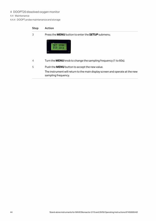
Step Action
3 Press the MENU button to enter the SETUP submenu.
4 Turn the MENU knob to change the sampling frequency (1 to 60s).
5 Push the MENU button to accept the new value.
The instrument will return to the main display screen and operate at the newsampling frequency.
4 DOOPT20 dissolved oxygen monitor4.4 Maintenance
4.4.4 DOOPT probe maintenance and storage
44 Stand-alone instruments for WAVE Bioreactor 2/10 and 20/50 Operating Instructions 87450009 AD

4.4.5 Instrument repairInstrument repair should only be done by service personnel authorized by Cytiva.
WARNINGElectrical shock hazard. Do not open any covers or replace parts.
4 DOOPT20 dissolved oxygen monitor4.4 Maintenance
4.4.5 Instrument repair
Stand-alone instruments for WAVE Bioreactor 2/10 and 20/50 Operating Instructions 87450009 AD 45

4.5 Troubleshooting
Error symptom Possible cause Corrective action
Not getting 0% Probe not properlyconnected
Check that the DOOPTprobe is connected andthat the temperatureprobe is connected (redLED is not lit).
Not getting 100% Faulty DOOPT probe • Check that thetemperature probe isconnected (red LED isnot lit).
• Try to achieve a 0%reading using theSPAN knob. If this isnot possible, replacethe DOOPT probe.
Reading precision is poor Some fluctuation (±5%),especially at high DOlevels is normal
The fluctuation can bedamped by adjusting thefilter time.
Low amplitude alarm The probe is not properlyconnected
Check that the probe isconnected correctly andthe plug secure. Cyclepower to the instrumentto reset.
The probe amplitude islow
If the error persists andthe amplitude is below2000, replace the probe.
No response from display The internal PC board isdefective
To check operation, turnoff power to DOOPT20and disconnect theprobe. Turn on power toDOOPT20 and lookdirectly into the probeconnector. A pulsing lightabout once a secondshould be flashing. If nopulsing light appears, theunit internal PC boardrequires replacement.Contact Cytiva Technicalsupport.
4 DOOPT20 dissolved oxygen monitor4.5 Troubleshooting
46 Stand-alone instruments for WAVE Bioreactor 2/10 and 20/50 Operating Instructions 87450009 AD

Error symptom Possible cause Corrective action
NEED 0% CAL or NEED100% CAL is displayed
The probe requires cali-bration
Calibrate the probe. If theproblem persists, replacethe probe.
Unable to select menus If you are unable to usethe PUSH FOR MENUbutton, the switch isdefective
Contact Cytiva Technicalsupport.
4 DOOPT20 dissolved oxygen monitor4.5 Troubleshooting
Stand-alone instruments for WAVE Bioreactor 2/10 and 20/50 Operating Instructions 87450009 AD 47

5 CO2MIX20 CO2/air controller
In this chapter
Section See page
5.1 Introduction/view 49
5.2 Installation 52
5.3 Operation 57
5.4 Maintenance 59
5.5 Troubleshooting 64
5 CO2MIX20 CO2/air controller
48 Stand-alone instruments for WAVE Bioreactor 2/10 and 20/50 Operating Instructions 87450009 AD

5.1 Introduction/viewCO2MIX20 is used to inflate and aerate the Cellbag bioreactors with air containing avariable carbon dioxide (CO2) concentration. CO2 from a pipeline or cylinder isconnected to the CO2 port. Air is drawn from the AIR IN port and mixed with the CO2.An internal CO2 sensor measures the CO2 concentration and controls the CO2 concen-tration in the outlet gas to any user-specified value from 0 up to 15%. The CO2 condi-tioned air is pumped from the MIX OUT port into the headspace of the Cellbagbioreactor to maintain bag pressure, and to provide air and carbon dioxide for aerationand pH control.
Note: CO2MIX20 is equipped with an internal bleeder valve. If the CO2 gas supplyis not turned off at the source, the CO2MIX20 will consume CO2 gas even ifthe CO2MIX20 instrument is turned off and in a non-working state.
The illustration below shows the location of the main parts of CO2MIX20.
10
13
12
11
Part Description
1 Airflowcontroller
2 HIGH PRES-SURE LED
3 PUMP ONswitch
4 Processcontroller
5 CO2 ONswitch
Part Description
6 CO2 PRES-SURE OKLED
7 CO2 IN port
8 AIR IN port
9 MIX OUTport
10 DataportConnectors
Part Description
11 Analogoutputconnector
12 Power switch,on (I), off (O)
13 Powerconnector
5 CO2MIX20 CO2/air controller5.1 Introduction/view
Stand-alone instruments for WAVE Bioreactor 2/10 and 20/50 Operating Instructions 87450009 AD 49

In this section
Section See page
5.1.1 CO2 leakage 51
5 CO2MIX20 CO2/air controller5.1 Introduction/view
50 Stand-alone instruments for WAVE Bioreactor 2/10 and 20/50 Operating Instructions 87450009 AD

5.1.1 CO2 leakageThe WAVE CO2MIX20 instrument utilizes an exhaust bleeder orifice to avoid pressurespikes during instrument operation. The CO2 exhaust levels will remain until the pres-surized CO2 supply is removed, regardless if the instrument is powered on or off.
5 CO2MIX20 CO2/air controller5.1 Introduction/view
5.1.1 CO2 leakage
Stand-alone instruments for WAVE Bioreactor 2/10 and 20/50 Operating Instructions 87450009 AD 51

5.2 Installation
WARNINGPlace CO2MIX20 instruments in a well ventilated environ-ment.
Failure to do so can lead to heightened CO2 concentrations.
Care should be taken to remove pressurized CO2 supply when notin use.
In this section
Section See page
5.2.1 Site requirements 53
5.2.2 Unpacking 54
5.2.3 Installation 55
5.2.4 Spare parts and accessories 56
5 CO2MIX20 CO2/air controller5.2 Installation
52 Stand-alone instruments for WAVE Bioreactor 2/10 and 20/50 Operating Instructions 87450009 AD

5.2.1 Site requirements
Parameter Requirement
Electrical power 24 V DC through an adapter
(110 to 120 V~ or
220 to 240 V~, 50/60 Hz)
Placement Stable laboratory bench
Operating temperature 4°C to 40°C
Humidity <95%, non-condensing
5 CO2MIX20 CO2/air controller5.2 Installation
5.2.1 Site requirements
Stand-alone instruments for WAVE Bioreactor 2/10 and 20/50 Operating Instructions 87450009 AD 53

5.2.2 UnpackingUnpack the equipment.
Please check the packing list to see that all items on the list are included. If any partsare missing, contact your Cytiva representative.
Place the equipment on a stable surface.
Check the equipment for any apparent damage before starting installation. Documentany damage carefully and contact your Cytiva representative.
5 CO2MIX20 CO2/air controller5.2 Installation
5.2.2 Unpacking
54 Stand-alone instruments for WAVE Bioreactor 2/10 and 20/50 Operating Instructions 87450009 AD

5.2.3 Installation
Connection overview
Figure 5.1: Diagram of CO2MIX20 connected to the base unit.
Step Action
1 Make sure that the CO2MIX20 and the Cellbag bioreactor are turned off.
2 Connect the transformer to a grounded power outlet.
3 Connect the transformer to the power connector located on the rear of theinstrument.
4 Press the power switch to the on (I) position.
5 Set the external CO2 source between 0.7 and 1 bar (10 and 15 psig). Connectthe external CO2 source to the CO2 IN port on the front panel.
6 If ambient air is to be mixed with the CO2 stream, leave the AIR IN portunconnected. Otherwise, connect the desired process air mixture to the AIRIN port. External gas pressure must be regulated to between 0.1 and 0.2 bar(1 and 3 psig).
7 Connect the MIX OUT port to the inlet air filter on the Cellbag bioreactorusing the tubing provided.
5 CO2MIX20 CO2/air controller5.2 Installation
5.2.3 Installation
Stand-alone instruments for WAVE Bioreactor 2/10 and 20/50 Operating Instructions 87450009 AD 55

5.2.4 Spare parts and accessoriesFor correct up to date information on spare parts and accessories, please refer to theweb address on the back cover or contact your local Cytiva representative.
5 CO2MIX20 CO2/air controller5.2 Installation
5.2.4 Spare parts and accessories
56 Stand-alone instruments for WAVE Bioreactor 2/10 and 20/50 Operating Instructions 87450009 AD
5.3 OperationSee Section 5.1 Introduction/view, on page 49 for location of buttons and Chapter 3Common process controllers, on page 19 for description of Process controller.
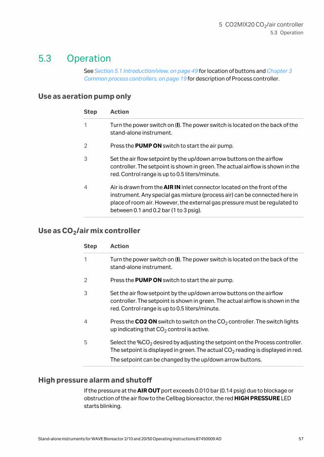
Use as aeration pump only
Step Action
1 Turn the power switch on (I). The power switch is located on the back of thestand-alone instrument.
2 Press the PUMP ON switch to start the air pump.
3 Set the air flow setpoint by the up/down arrow buttons on the airflowcontroller. The setpoint is shown in green. The actual airflow is shown in thered. Control range is up to 0.5 liters/minute.
4 Air is drawn from the AIR IN inlet connector located on the front of theinstrument. Any special gas mixture (process air) can be connected here inplace of room air. However, the external gas pressure must be regulated tobetween 0.1 and 0.2 bar (1 to 3 psig).
Use as CO2/air mix controller
Step Action
1 Turn the power switch on (I). The power switch is located on the back of thestand-alone instrument.
2 Press the PUMP ON switch to start the air pump.
3 Set the air flow setpoint by the up/down arrow buttons on the airflowcontroller. The setpoint is shown in green. The actual airflow is shown in thered. Control range is up to 0.5 liters/minute.
4 Press the CO2 ON switch to switch on the CO2 controller. The switch lightsup indicating that CO2 control is active.
5 Select the %CO2 desired by adjusting the setpoint on the Process controller.The setpoint is displayed in green. The actual CO2 reading is displayed in red.
The setpoint can be changed by the up/down arrow buttons.
High pressure alarm and shutoffIf the pressure at the AIR OUT port exceeds 0.010 bar (0.14 psig) due to blockage orobstruction of the air flow to the Cellbag bioreactor, the red HIGH PRESSURE LEDstarts blinking.
5 CO2MIX20 CO2/air controller5.3 Operation
Stand-alone instruments for WAVE Bioreactor 2/10 and 20/50 Operating Instructions 87450009 AD 57

If the overpressure condition continues for longer than 1 to 2 minutes, the airpumpshuts down preventing the pressure from rising higher. When the overpressure condi-tion clears, the airpump resumes operation.
Note: CO2MIX20 is equipped with a bleeder valve. If the CO2 gas source is notturned off the CO2MIX20 will consume CO2 gas, even if the CO2MIX20 isturned off.
WARNINGCarbon dioxide can cause asphyxiation. Make sure that theventilation is sufficient. Avoiding installing the unit in closedspaces.
5 CO2MIX20 CO2/air controller5.3 Operation
58 Stand-alone instruments for WAVE Bioreactor 2/10 and 20/50 Operating Instructions 87450009 AD

5.4 Maintenance
In this section
Section See page
5.4.1 Maintenance frequency 60
5.4.2 Cleaning 61
5.4.3 Calibration 62
5.4.4 Instrument repair 63
5 CO2MIX20 CO2/air controller5.4 Maintenance
Stand-alone instruments for WAVE Bioreactor 2/10 and 20/50 Operating Instructions 87450009 AD 59

5.4.1 Maintenance frequencyRegular maintenance of the WAVE system instruments is essential for reliable results.Perform maintenance at recommended frequencies.
Frequency Action Section
Before and after everyuse
Keep instrument clean anddry
Section 5.4.2 Cleaning, onpage 61
Every six months CO2 sensor calibration Section 5.4.3 Calibration,on page 62
When required Repair broken instrument.
Note:All repairs should be doneby service personnelauthorized by Cytiva.
Section 5.4.4 Instrumentrepair, on page 63
5 CO2MIX20 CO2/air controller5.4 Maintenance
5.4.1 Maintenance frequency
60 Stand-alone instruments for WAVE Bioreactor 2/10 and 20/50 Operating Instructions 87450009 AD

5.4.2 CleaningKeep the instruments dry and clean. The instruments must be turned off andunplugged before cleaning begins. Clean the exterior of the instruments with a cloth,damp with water and – if required – alcohol. Do not use abrasive cleaners. Water shouldnot be applied directly to the instruments. Make sure that the instruments arecompletely dry before plugging them in.
5 CO2MIX20 CO2/air controller5.4 Maintenance
5.4.2 Cleaning
Stand-alone instruments for WAVE Bioreactor 2/10 and 20/50 Operating Instructions 87450009 AD 61

5.4.3 CalibrationThe CO2 sensor needs to be recalibrated every six months to ensure accuracy. This canbe done by returning the unit to Cytiva. Contact your Cytiva representative for moreinformation and help.
5 CO2MIX20 CO2/air controller5.4 Maintenance
5.4.3 Calibration
62 Stand-alone instruments for WAVE Bioreactor 2/10 and 20/50 Operating Instructions 87450009 AD

5.4.4 Instrument repairInstrument repair should only be done by service personnel authorized by Cytiva.
WARNINGElectrical shock hazard. Do not open any covers or replace parts.
5 CO2MIX20 CO2/air controller5.4 Maintenance
5.4.4 Instrument repair
Stand-alone instruments for WAVE Bioreactor 2/10 and 20/50 Operating Instructions 87450009 AD 63

5.5 Troubleshooting
Error symptom Possible cause Corrective action
The display shows a CO2
concentration in airwhich deviates from theexpected value(0.0% to 0.1%).
A minor deviation fromthe expected value is notunusual. The tolerance ofthe CO2 sensor is ±0.38%in the range 0% to 7.5%CO2.
Contact a service repre-sentative.
CO2 reading keepsdrifting down
The CO2 gas supply pres-sure is too low
Check that the green CO2
inlet pressure light is lit.The CO2 supply pressuremust between 0.7 and 1.0bar (10 and 15 psig).
The CO2 consumption islarger than expected.
The internal bleedervalve leaks CO2 duringsystem shut down.
Turn off CO2 at thesource.
Faulty CO2 control The CO2 supply is notproperly connected
Verify that CO2 isconnected to the correctinlet port. Check that theair pump is on and thatthe flow rate is between0.1 and 0.5 liters/minute.Check that the CO2
switch is on.
Wrong setpoint set Check the setpoint onthe controller.
The Cellbag bioreactordoes not stay inflated
No air flow Verify that there is airflowto the Cellbag bioreactor.
5 CO2MIX20 CO2/air controller5.5 Troubleshooting
64 Stand-alone instruments for WAVE Bioreactor 2/10 and 20/50 Operating Instructions 87450009 AD

Error symptom Possible cause Corrective action
Faulty check valve Check that the checkvalve on the Cellbagbioreactor is correctlyinstalled. Close off theCellbag bioreactor outletusing the pinch clampand see if the Cellbagbioreactor inflates. Thenconfirm that the checkvalve is working byconnecting a shortlength of tubing to thecheck valve outlet anddip it into water. Tubingshould be immersed to adepth of 5 to 10 mm.Opening the outlet pinchvalve should causebubbles to appear andbubbles should continueto flow as the flow andpressure stabilizes.
5 CO2MIX20 CO2/air controller5.5 Troubleshooting
Stand-alone instruments for WAVE Bioreactor 2/10 and 20/50 Operating Instructions 87450009 AD 65
6 CO2MIX20-R CO2/air controller
In this chapter
Section See page
6.1 Introduction/view 67
6.2 Installation 70
6.3 Operation 75
6.4 Maintenance 76
6.5 Troubleshooting 81
6 CO2MIX20-R CO2/air controller
66 Stand-alone instruments for WAVE Bioreactor 2/10 and 20/50 Operating Instructions 87450009 AD

6.1 Introduction/viewCO2MIX20-R (rotameter model) is used to inflate and aerate the Cellbag bioreactorswith air containing a variable carbon dioxide (CO2) concentration. CO2 from a pipelineor cylinder is connected to the CO2MIX20-R, which has a precision regulator to adjustthe gas pressure. Air is drawn from the AIR IN and mixed with the CO2 (connected toCO2 IN). An internal CO2 sensor measures the CO2 concentration and controls it toany user-specified value up to 15%. The CO2 conditioned air is pumped from the MIXOUT port into the headspace of the Cellbag bioreactor to maintain bag pressure, andto provide air and carbon dioxide for aeration and pH control.
Note: CO2MIX20-R is equipped with a bleeder valve. If the CO2 gas source is notturned off, the CO2MIX20-R will consume CO2 gas even if the CO2MIX20-Ris turned off.
The illustration below shows the location of the main parts of CO2MIX20-R.
11
14
13
12
1 2
9 8 5
4
3
7 610
Part Description
1 Processcontroller
2 CO2 gauge
3 Airflow rota-meter
4 Flow rateadjust
5 MIX OUTport
Part Description
6 CO2 pressureregulator
7 AIR IN port
8 PUMP ONswitch
9 CO2 IN port
10 CO2 ONswitch
Part Description
11 DataportConnectors
12 Analogoutputconnector
13 Power switch,on (I), off (O)
14 Powerconnector
6 CO2MIX20-R CO2/air controller6.1 Introduction/view
Stand-alone instruments for WAVE Bioreactor 2/10 and 20/50 Operating Instructions 87450009 AD 67

In this section
Section See page
6.1.1 CO2 leakage 69
6 CO2MIX20-R CO2/air controller6.1 Introduction/view
68 Stand-alone instruments for WAVE Bioreactor 2/10 and 20/50 Operating Instructions 87450009 AD

6.1.1 CO2 leakageThe WAVE CO2MIX20 instrument utilizes an exhaust bleeder orifice to avoid pressurespikes during instrument operation. The CO2 exhaust levels will remain until the pres-surized CO2 supply is removed, regardless if the instrument is powered on or off.
6 CO2MIX20-R CO2/air controller6.1 Introduction/view
6.1.1 CO2 leakage
Stand-alone instruments for WAVE Bioreactor 2/10 and 20/50 Operating Instructions 87450009 AD 69

6.2 Installation
WARNINGPlace CO2MIX20-R instruments in a well ventilated environ-ment.
Failure to do so can lead to heightened CO2 concentrations.
Care should be taken to remove pressurized CO2 supply when notin use.
In this section
Section See page
6.2.1 Site requirements 71
6.2.2 Unpacking 72
6.2.3 Installation 73
6.2.4 Spare parts and accessories 74
6 CO2MIX20-R CO2/air controller6.2 Installation
70 Stand-alone instruments for WAVE Bioreactor 2/10 and 20/50 Operating Instructions 87450009 AD

6.2.1 Site requirements
Parameter Requirement
Electrical power 24 V DC through an adapter
(110 to 120 V~ or
220 to 240 V~, 50/60 Hz)
Placement Stable laboratory bench
Operating temperature 4°C to 40°C
Humidity <95%, non-condensing
6 CO2MIX20-R CO2/air controller6.2 Installation
6.2.1 Site requirements
Stand-alone instruments for WAVE Bioreactor 2/10 and 20/50 Operating Instructions 87450009 AD 71

6.2.2 UnpackingUnpack the equipment.
Please check the packing list to see that all items on the list are included. If any partsare missing, contact your Cytiva representative.
Place the equipment on a stable surface.
Check the equipment for any apparent damage before starting installation. Documentany damage carefully and contact your Cytiva representative.
Connection overview
6 CO2MIX20-R CO2/air controller6.2 Installation
6.2.2 Unpacking
72 Stand-alone instruments for WAVE Bioreactor 2/10 and 20/50 Operating Instructions 87450009 AD

6.2.3 Installation
Step Action
1 Make sure that the Cellbag bioreactor and the CO2MIX20-R are turned off.
2 Connect the transformer to the power connector, located on the rear of theinstrument.
3 Connect the transformer to a grounded power outlet.
4 Press the power switch to the on position. Allow five minutes for the instru-ment to warm up and the reading to stabilize.
5 Set the external CO2 source between 0.7 and 1.0 bar (10 and 15 psig).Connect the external CO2 source to the CO2 IN port on the front panel.
6 Adjust the CO2 pressure to 0.4 bar using the regulator knob and the and thegauge located on the front panel of the instrument. The regulator knob mustbe pulled to out to unlock.
7 If ambient air is to be mixed with the CO2 stream, leave the AIR IN portunconnected. Otherwise, connect the desired air mixture to the AIR IN port.External gas pressure must be regulated to between 0.1 and 0.2 bar (1 and 3psig).
8 Connect the MIX OUT port to the inlet filter on the Cellbag bioreactor usingthe tubing provided. The CO2 /air mixture is pumped out from this port.
6 CO2MIX20-R CO2/air controller6.2 Installation
6.2.3 Installation
Stand-alone instruments for WAVE Bioreactor 2/10 and 20/50 Operating Instructions 87450009 AD 73
6.2.4 Spare parts and accessoriesFor correct up to date information on spare parts and accessories, see the web addresson the back cover or contact your local Cytiva representative.
6 CO2MIX20-R CO2/air controller6.2 Installation
6.2.4 Spare parts and accessories
74 Stand-alone instruments for WAVE Bioreactor 2/10 and 20/50 Operating Instructions 87450009 AD

6.3 OperationSee Section 6.1 Introduction/view, on page 67 for location of buttons and Chapter 3Common process controllers, on page 19 for description of Process controller.
Use as aeration pump only
Step Action
1 Turn the power switch on (I). The power switch is located on the back of thestand-alone instrument.
2 Press the PUMP ON switch to start the air pump.
3 Adjust the flow rate by turning the flow rate adjust knob.
4 Air is drawn from the AIR IN inlet connector located on the front of theinstrument. Any special gas mixture can be connected here in place of roomair. External gas pressure must be regulated to between 0.1 and 0.2 bar (1 to3 psig).
Note:The CO2 pressure regulator (part 6 in Section 6.1 Introduction/view, on page67) can not be used for controlling the external gas pressure.
Use as CO2/air mix controller
Step Action
1 Turn the power switch on (I). The power switch is located on the back of thestand-alone instrument.
2 Press the PUMP ON switch to start the air pump.
3 Press the CO2 button to switch on the CO2 controller. The button lights upindicating that CO2 control is active.
4 Select the %CO2 desired by adjusting the setpoint on the Process controller.The setpoint is displayed in green. The actual CO2 reading is displayed in red.
The setpoint can be changed by the up/down arrow buttons.
6 CO2MIX20-R CO2/air controller6.3 Operation
Stand-alone instruments for WAVE Bioreactor 2/10 and 20/50 Operating Instructions 87450009 AD 75

6.4 Maintenance
In this section
Section See page
6.4.1 Maintenance frequency 77
6.4.2 Cleaning 78
6.4.3 Calibration 79
6.4.4 Instrument repair 80
6 CO2MIX20-R CO2/air controller6.4 Maintenance
76 Stand-alone instruments for WAVE Bioreactor 2/10 and 20/50 Operating Instructions 87450009 AD

6.4.1 Maintenance frequencyRegular maintenance of the WAVE system instruments is essential for reliable results.Perform maintenance at recommended frequencies.
Frequency Action Section
Before and after everyuse
Keep instrument clean anddry
Section 6.4.2 Cleaning, onpage 78
Every six months CO2 sensor calibration Section 6.4.3 Calibration,on page 79
When required Repair broken instrument.
Note:All repairs should be doneby service personnelauthorized by Cytiva.
Section 6.4.4 Instrumentrepair, on page 80
6 CO2MIX20-R CO2/air controller6.4 Maintenance
6.4.1 Maintenance frequency
Stand-alone instruments for WAVE Bioreactor 2/10 and 20/50 Operating Instructions 87450009 AD 77

6.4.2 CleaningKeep the instruments dry and clean. The instruments must be turned off andunplugged before cleaning begins. Clean the exterior of the instruments with a dampcloth with water and, if required, alcohol. Do not use abrasive cleaners. Water shouldnot be applied directly to the instruments. Make sure that the instruments arecompletely dry before plugging them in.
6 CO2MIX20-R CO2/air controller6.4 Maintenance
6.4.2 Cleaning
78 Stand-alone instruments for WAVE Bioreactor 2/10 and 20/50 Operating Instructions 87450009 AD

6.4.3 CalibrationThe CO2 sensor needs to be recalibrated every six months to ensure accuracy. This maybe done by returning the unit to the Cytiva. Contact Cytiva for more information andhelp.
6 CO2MIX20-R CO2/air controller6.4 Maintenance
6.4.3 Calibration
Stand-alone instruments for WAVE Bioreactor 2/10 and 20/50 Operating Instructions 87450009 AD 79
6.4.4 Instrument repairInstrument repair should only be done by service personnel authorized by Cytiva.
WARNINGElectrical shock hazard. Do not open any covers or replace parts.
6 CO2MIX20-R CO2/air controller6.4 Maintenance
6.4.4 Instrument repair
80 Stand-alone instruments for WAVE Bioreactor 2/10 and 20/50 Operating Instructions 87450009 AD

6.5 Troubleshooting
Error symptom Possible cause Corrective action
The display shows a CO2
concentration in airwhich deviates from theexpected value(0.0% to 0.1%).
A minor deviation fromthe expected value is notunusual. The tolerance ofthe CO2 sensor is ±0.38%in the range 0% to 7.5%CO2.
Contact a service repre-sentative.
CO2 reading keepsdrifting down
The CO2 gas supply pres-sure is too low
Check that the green CO2
inlet pressure light is lit.The CO2 supply pressuremust between 0.7 and 1.0bar (10 and 15 psig).
Faulty CO2 control The CO2 supply is notproperly connected
Verify that CO2 isconnected to the correctinlet port. Check that theair pump is on and thatthe flow rate is between0.1 and 0.5 liters/minute.Check that the CO2
switch is on.
Wrong setpoint set Check the setpoint onthe controller.
The CO2 consumption islarger than expected.
The internal bleedervalve leaks CO2 duringsystem shut down.
Turn off CO2 at thesource.
No reading on rotameter Obstructed airflow Check that airflow to theCellbag bioreactor is notobstructed. Verify thatthe pump is working bydisconnecting the MIXOUT coupling on theinstrument and theCellbag.
The Cellbag bioreactordoes not stay inflated
No air flow Verify that there is airflowto the Cellbag bioreactor.
6 CO2MIX20-R CO2/air controller6.5 Troubleshooting
Stand-alone instruments for WAVE Bioreactor 2/10 and 20/50 Operating Instructions 87450009 AD 81

Error symptom Possible cause Corrective action
Faulty check valve Check that the checkvalve on the Cellbagbioreactor is correctlyinstalled. Close off theCellbag bioreactor outletusing the pinch clampand see if the Cellbagbioreactor inflates. Thenconfirm that the checkvalve is working byconnecting a shortlength of tubing to thecheck valve outlet anddip it into water. Tubingshould be immersed to adepth of 5 to 10 mm.Opening the outlet pinchvalve should causebubbles to appear andbubbles should continueto flow as the flow andpressure stabilizes.
6 CO2MIX20-R CO2/air controller6.5 Troubleshooting
82 Stand-alone instruments for WAVE Bioreactor 2/10 and 20/50 Operating Instructions 87450009 AD

7 O2MIX20 O2/air controller
In this chapter
Section See page
7.1 Introduction/view 84
7.2 Installation 85
7.3 Operation 90
7.4 Maintenance 92
7.5 Troubleshooting 97
7 O2MIX20 O2/air controller
Stand-alone instruments for WAVE Bioreactor 2/10 and 20/50 Operating Instructions 87450009 AD 83
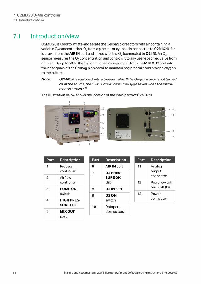
7.1 Introduction/viewO2MIX20 is used to inflate and aerate the Cellbag bioreactors with air containing avariable O2 concentration. O2 from a pipeline or cylinder is connected to O2MIX20. Airis drawn from the AIR IN port and mixed with the O2 (connected to O2 IN). An O2
sensor measures the O2 concentration and controls it to any user-specified value fromambient O2 up to 50%. The O2 conditioned air is pumped from the MIX OUT port intothe headspace of the Cellbag bioreactor to maintain bag pressure and provide oxygento the culture.
Note: O2MIX20 is equipped with a bleeder valve. If the O2 gas source is not turnedoff at the source, the O2MIX20 will consume O2 gas even when the instru-ment is turned off.
The illustration below shows the location of the main parts of O2MIX20.
10
13
12
11
1
5
4
3
2
9
7
6
8
Part Description
1 Processcontroller
2 Airflowcontroller
3 PUMP ONswitch
4 HIGH PRES-SURE LED
5 MIX OUTport
Part Description
6 AIR IN port
7 O2 PRES-SURE OKLED
8 O2 IN port
9 O2 ONswitch
10 DataportConnectors
Part Description
11 Analogoutputconnector
12 Power switch,on (I), off (O)
13 Powerconnector
7 O2MIX20 O2/air controller7.1 Introduction/view
84 Stand-alone instruments for WAVE Bioreactor 2/10 and 20/50 Operating Instructions 87450009 AD

7.2 Installation
In this section
Section See page
7.2.1 Site requirements 86
7.2.2 Unpacking 87
7.2.3 Installation 88
7.2.4 Spare parts and accessories 89
7 O2MIX20 O2/air controller7.2 Installation
Stand-alone instruments for WAVE Bioreactor 2/10 and 20/50 Operating Instructions 87450009 AD 85

7.2.1 Site requirements
Parameter Requirement
Electrical power 24 V DC through an adapter
(110 to 120 V~ or
220 to 240 V~, 50/60 Hz)
Placement Stable laboratory bench
Operating temperature 4°C to 40°C
Humidity <95%, non-condensing
7 O2MIX20 O2/air controller7.2 Installation
7.2.1 Site requirements
86 Stand-alone instruments for WAVE Bioreactor 2/10 and 20/50 Operating Instructions 87450009 AD

7.2.2 UnpackingUnpack the equipment.
Please check the packing list to see that all items on the list are included. If any partsare missing, contact your Cytiva representative.
Place the equipment on a stable surface.
Check the equipment for any apparent damage before starting installation. Documentany damage carefully and contact your Cytiva representative.
7 O2MIX20 O2/air controller7.2 Installation
7.2.2 Unpacking
Stand-alone instruments for WAVE Bioreactor 2/10 and 20/50 Operating Instructions 87450009 AD 87

7.2.3 Installation
WARNINGFire hazard. Oxygen can leak out and cause fire. Do not open anycovers or replace parts. Shut off the O2 source when not in use.
Step Action
1 Make sure that the O2MIX20 and the Cellbag bioreactor are powered off.
2 Connect the transformer to a grounded power outlet.
3 Connect the transformer to the power connector located on the rear of theinstrument.
4 Press the power switch to the on position. Allow five minutes for the instru-ment to warm up and the reading to stabilize.
5 Set the external O2 source between 0.7 and 1.0 bar (10 and 15 psig). Connectthe external O2 source to the O2 IN port on the front panel.
6 If ambient air is to be mixed with O2, leave the AIR IN port unconnected. Ifprocess air is desired, connect this air to the AIR IN port. External gas pres-sure must be controlled to between 0.1 and 0.2 bar (1 and 3 psig).
7 Connect the MIX OUT port to the inlet filter on the Cellbag bioreactor usingthe tubing provided with the O2MIX instrument.
7 O2MIX20 O2/air controller7.2 Installation
7.2.3 Installation
88 Stand-alone instruments for WAVE Bioreactor 2/10 and 20/50 Operating Instructions 87450009 AD

7.2.4 Spare parts and accessoriesFor correct up to date information on spare parts and accessories, please refer to theweb address on the back cover or contact your local Cytiva representative.
7 O2MIX20 O2/air controller7.2 Installation
7.2.4 Spare parts and accessories
Stand-alone instruments for WAVE Bioreactor 2/10 and 20/50 Operating Instructions 87450009 AD 89

7.3 OperationSee Section 7.1 Introduction/view, on page 84 for location of buttons and Chapter 3Common process controllers, on page 19 for description of Process controller.
Use as aeration pump only
Step Action
1 Turn the power switch on (I). The power switch is located on the back of thestand-alone instrument.
2 Press the PUMP ON switch to start the air pump.
3 Set the air flow setpoint by the up/down arrow buttons on the airflowcontroller. The setpoint is shown in green. The actual airflow is shown in thered. Control range is up to 0.5 liters/minute.
4 Air is drawn from the AIR IN inlet connector located on the front of theinstrument. Any special gas mixture, such as process air, can be connectedhere in place of ambient air. External gas pressure must be controlled tobetween 0.1 and 0.2 bar (1 to 3 psig).
Use as O2/air mix controller
Step Action
1 Turn the power switch on (I). The power switch is located on the back of thestand-alone instrument.
2 Press the PUMP ON switch to start the air pump.
3 Set the air flow setpoint by the up/down arrow buttons on the airflowcontroller. The setpoint is shown in green. The actual airflow is shown in thered. Control range is up to 0.5 liters/minute.
4 Press the O2 ON switch to switch on the O2 controller. The switch lights upindicating that O2 control is active.
5 Select the %O2 desired by adjusting the setpoint on the Process controller.The setpoint is displayed in green. The actual O2 reading is displayed in red.
The setpoint can be changed by the up/down arrow buttons.
High pressure alarm and shutoffIf the pressure at the AIR OUT port exceeds 7.5 mbar (0.11 psig) due to blockage orobstruction of the air flow to the Cellbag bioreactor, the red HIGH PRESSURE LEDstarts blinking. If the overpressure condition continues for longer than 1 to 2 minutes,the internal air flow valve shuts down preventing the pressure from rising higher. Whenthe overpressure condition clears, the airpump resumes operation.
7 O2MIX20 O2/air controller7.3 Operation
90 Stand-alone instruments for WAVE Bioreactor 2/10 and 20/50 Operating Instructions 87450009 AD

Note: O2MIX20 is equipped with a bleeder valve. If the O2 gas source is not turnedoff the O2MIX20 will consume O2 gas even if the O2MIX20 is turned off.
7 O2MIX20 O2/air controller7.3 Operation
Stand-alone instruments for WAVE Bioreactor 2/10 and 20/50 Operating Instructions 87450009 AD 91

7.4 Maintenance
In this section
Section See page
7.4.1 Maintenance frequency 93
7.4.2 Cleaning 94
7.4.3 Calibration 95
7.4.4 Instrument repair 96
7 O2MIX20 O2/air controller7.4 Maintenance
92 Stand-alone instruments for WAVE Bioreactor 2/10 and 20/50 Operating Instructions 87450009 AD

7.4.1 Maintenance frequencyRegular maintenance of the WAVE system instruments is essential for reliable results.Perform maintenance at recommended frequencies.
Frequency Action Section
Before and after everyuse
Keep instrument clean anddry
Section 7.4.2 Cleaning, onpage 94
Every six months O2 sensor calibration Section 7.4.3 Calibration,on page 95
When required Repair broken instrument.
Note:All repairs should be doneby service personnelauthorized by Cytiva.
Section 7.4.4 Instrumentrepair, on page 96
7 O2MIX20 O2/air controller7.4 Maintenance
7.4.1 Maintenance frequency
Stand-alone instruments for WAVE Bioreactor 2/10 and 20/50 Operating Instructions 87450009 AD 93

7.4.2 CleaningKeep the instruments dry and clean. The instruments must be turned off andunplugged before cleaning begins. Clean the exterior of the instruments with a dampcloth with water and, if required, alcohol. Do not use abrasive cleaners. Water shouldnot be applied directly to the instruments. Make sure that the instruments arecompletely dry before plugging them in.
7 O2MIX20 O2/air controller7.4 Maintenance
7.4.2 Cleaning
94 Stand-alone instruments for WAVE Bioreactor 2/10 and 20/50 Operating Instructions 87450009 AD
7.4.3 CalibrationThe O2 sensor does not need to be calibrated. Over time (10 years typical), the sensorwill decay and will need to be replaced. Calibration can easily be checked by turning thecontrol function off. Turn the pump on so that air is introduced to the sensor. Thedisplay should show 21% oxygen. (+/-0.6%).
For recalibration or sensor replacement please contact Cytiva for return of the unit forservice.
7 O2MIX20 O2/air controller7.4 Maintenance
7.4.3 Calibration
Stand-alone instruments for WAVE Bioreactor 2/10 and 20/50 Operating Instructions 87450009 AD 95

7.4.4 Instrument repairInstrument repair should only be done by service personnel authorized by Cytiva.
WARNINGElectrical shock hazard. Do not open any covers or replace parts.
7 O2MIX20 O2/air controller7.4 Maintenance
7.4.4 Instrument repair
96 Stand-alone instruments for WAVE Bioreactor 2/10 and 20/50 Operating Instructions 87450009 AD

7.5 Troubleshooting
Error symptom Possible cause Corrective action
The display shows a O2
concentration in airwhich deviates from theexpected value (21.0%).
A minor deviation fromthe expected value is notunusual. The tolerance ofthe O2 sensor is ±0.6% inthe range 21% to 40% O2
If the reading is notwithin the tolerance, theO2 offset can be adjusted.
O2 reading keeps driftingdown
The O2 gas supply pres-sure is too low
Check that the green O2
inlet pressure light is lit.The O2 supply pressuremust between 0.7 and 1.0bar (10 and 15 psig).
The O2 consumption islarger than expected.
The internal bleedervalve leaks O2 duringsystem shut down.
Turn off O2 at the sourcewhen the O2MIX20instrument is not used.
Faulty O2 control The O2 supply is not prop-erly connected
Verify that O2 isconnected to the correctinlet port. Check that theO2 supply pressure is setto 0.7 bar minimum.Check that the air pumpis on and that the flowrate is between 0.1 and0.5 liters/ minute. Checkthat the O2 switch is on.
Wrong setpoint set Check the setpoint onthe controller.
7 O2MIX20 O2/air controller7.5 Troubleshooting
Stand-alone instruments for WAVE Bioreactor 2/10 and 20/50 Operating Instructions 87450009 AD 97

8 O2MIX20-R O₂/air controller
In this chapter
Section See page
8.1 Introduction/view 99
8.2 Installation 100
8.3 Operation 105
8.4 Maintenance 106
8.5 Troubleshooting 111
8 O2MIX20-R O₂/air controller
98 Stand-alone instruments for WAVE Bioreactor 2/10 and 20/50 Operating Instructions 87450009 AD

8.1 Introduction/viewO2MIX20-R (rotameter model) is used to inflate and aerate Cellbag bioreactors with aircontaining a variable O2 concentration. O2 from a pipeline or cylinder is connected toO2MIX20-R which has a precision regulator to adjust the gas pressure. Air is drawnfrom the AIR IN port and mixed with the O2 (connected to O2 IN). An O2 sensor meas-ures the O2 concentration and controls it to any user-specified value from 21% to 50%.The O2 conditioned air is pumped from the MIX OUT port into the headspace of theCellbag bioreactor to maintain bag pressure, and to provide oxygen to the culture.
Note: O2MIX20-R is equipped with a bleeder valve. If the O2 gas source is notturned off the O2MIX20-R will consume O2 gas even if the O2MIX20-Rinstrument is turned off.
The illustration below shows the location of the main parts of O2MIX20-R.
11
14
13
123
56
4
10 789
21
Part Description
1 Processcontroller
2 O2 gauge
3 Airflow rota-meter
4 Flow rateadjust
5 MIX OUTport
Part Description
6 O2 pressureregulator
7 AIR IN port
8 PUMP ONswitch
9 O2 IN port
10 O2 ONswitch
Part Description
11 DataportConnectors
12 Analogoutputconnector
13 Power switch,on (I), off (O)
14 Powerconnector
8 O2MIX20-R O₂/air controller8.1 Introduction/view
Stand-alone instruments for WAVE Bioreactor 2/10 and 20/50 Operating Instructions 87450009 AD 99

8.2 Installation
In this section
Section See page
8.2.1 Site requirements 101
8.2.2 Unpacking 102
8.2.3 Installation 103
8.2.4 Spare parts and accessories 104
8 O2MIX20-R O₂/air controller8.2 Installation
100 Stand-alone instruments for WAVE Bioreactor 2/10 and 20/50 Operating Instructions 87450009 AD

8.2.1 Site requirements
Parameter Requirement
Electrical power 24 V DC through an adapter
(110 to 120 V~ or
220 to 240 V~, 50/60 Hz)
Placement Stable laboratory bench
Operating temperature 4°C to 40°C
Humidity <95%, non-condensing
8 O2MIX20-R O₂/air controller8.2 Installation
8.2.1 Site requirements
Stand-alone instruments for WAVE Bioreactor 2/10 and 20/50 Operating Instructions 87450009 AD 101

8.2.2 UnpackingUnpack the equipment.
Please check the packing list to see that all items on the list are included. If any partsare missing, contact your Cytiva representative.
Place the equipment on a stable surface.
Check the equipment for any apparent damage before starting installation. Documentany damage carefully and contact your Cytiva representative.
8 O2MIX20-R O₂/air controller8.2 Installation
8.2.2 Unpacking
102 Stand-alone instruments for WAVE Bioreactor 2/10 and 20/50 Operating Instructions 87450009 AD

8.2.3 Installation
WARNINGFire hazard. Oxygen can leak out and cause fire. Do not open anycovers or replace parts. Shut off the O2 source when not in use.
Step Action
1 Make sure that the O2MIX20-R and the Cellbag bioreactor are powered off.
2 Connect the transformer to a grounded power outlet.
3 Connect the transformer to the power connector located on the rear of theinstrument.
4 Press the power switch to the on position. Allow five minutes for the instru-ment to warm up and the reading to stabilize.
5 Set the external O2 source between 0.7 and 1.0 bar (10 and 15 psig). Connectthe external O2 source to the O2 IN port on the front panel.
6 Adjust the O2 pressure to 0.4 bar using the regulator knob and the and thegauge located on the front panel of the instrument. The regulator knob mustbe pulled to out to unlock.
7 If ambient air is to be mixed with the O2 stream, leave the AIR IN port uncon-nected. Otherwise, connect the desired air mixture to the AIR IN port.External gas pressure must be regulated to between 0.1 and 0.2 bar (1 and 3psig).
8 Connect the MIX OUT port to the inlet filter on the Cellbag bioreactor usingthe tubing provided. The O2 /air mixture is pumped out from this port.
8 O2MIX20-R O₂/air controller8.2 Installation
8.2.3 Installation
Stand-alone instruments for WAVE Bioreactor 2/10 and 20/50 Operating Instructions 87450009 AD 103

8.2.4 Spare parts and accessoriesFor correct up to date information on spare parts and accessories, see the web addresson the back cover or contact your local Cytiva representative.
8 O2MIX20-R O₂/air controller8.2 Installation
8.2.4 Spare parts and accessories
104 Stand-alone instruments for WAVE Bioreactor 2/10 and 20/50 Operating Instructions 87450009 AD

8.3 OperationSee Section 8.1 Introduction/view, on page 99 for location of buttons and Chapter 3Common process controllers, on page 19 for description of Process controller.
Use as aeration pump only
Step Action
1 Turn the power switch on (I). The power switch is located on the back of thestand-alone instrument.
2 Press the PUMP ON switch to start the air pump.
3 Adjust the flow rate by turning the flow rate adjust knob.
4 Air is drawn from the AIR IN inlet connector located on the front of theinstrument. Any special gas mixture can be connected here in place of roomair. External gas pressure must be regulated to between 0.1 and 0.2 bar (1 to3 psig).
Use as O2/air mix controller
Step Action
1 Turn the power switch on (I). The power switch is located on the back of thestand-alone instrument.
2 Press the PUMP ON switch to start the air pump.
3 Adjust the flow rate by turning the flow rate adjust knob.
4 Press the O2 button to switch on the O2 controller. The button lights up indi-cating that O2 control is active.
5 Select the %O2 desired by adjusting the setpoint on the Process controller.The setpoint is displayed in green. The actual O2 reading is displayed in red.
The setpoint can be changed by the up/down arrow buttons.
8 O2MIX20-R O₂/air controller8.3 Operation
Stand-alone instruments for WAVE Bioreactor 2/10 and 20/50 Operating Instructions 87450009 AD 105

8.4 Maintenance
In this section
Section See page
8.4.1 Maintenance frequency 107
8.4.2 Cleaning 108
8.4.3 Calibration 109
8.4.4 Instrument repair 110
8 O2MIX20-R O₂/air controller8.4 Maintenance
106 Stand-alone instruments for WAVE Bioreactor 2/10 and 20/50 Operating Instructions 87450009 AD

8.4.1 Maintenance frequencyRegular maintenance of the WAVE system instruments is essential for reliable results.
Perform maintenance at recommended frequencies.
Frequency Action Section
Before and after everyuse
Keep instrument clean anddry
Section 8.4.2 Cleaning, onpage 108
Every six months O2 sensor calibration Section 8.4.3 Calibration,on page 109
When required Repair broken instrument.
Note:All repairs should be doneby service personnelauthorized by Cytiva.
Section 8.4.4 Instrumentrepair, on page 110
8 O2MIX20-R O₂/air controller8.4 Maintenance
8.4.1 Maintenance frequency
Stand-alone instruments for WAVE Bioreactor 2/10 and 20/50 Operating Instructions 87450009 AD 107

8.4.2 CleaningKeep the instruments dry and clean. The instruments must be turned off andunplugged before cleaning begins. Clean the exterior of the instruments with a dampcloth with water and, if required, alcohol. Do not use abrasive cleaners. Water shouldnot be applied directly to the instruments. Make sure that the instruments arecompletely dry before plugging them in.
8 O2MIX20-R O₂/air controller8.4 Maintenance
8.4.2 Cleaning
108 Stand-alone instruments for WAVE Bioreactor 2/10 and 20/50 Operating Instructions 87450009 AD

8.4.3 CalibrationThe O2 sensor does not need to be calibrated. Over time (10 years typical), the sensorwill decay and will need to be replaced. Calibration can easily be checked by turning thecontrol function off. Turn the pump on so that air is introduced to the sensor. Thedisplay should show approximately 21% oxygen. (+/-0.6%).
For recalibration or sensor replacement please contact Cytiva for return of the unit forservice.
8 O2MIX20-R O₂/air controller8.4 Maintenance
8.4.3 Calibration
Stand-alone instruments for WAVE Bioreactor 2/10 and 20/50 Operating Instructions 87450009 AD 109

8.4.4 Instrument repairInstrument repair should only be done by service personnel authorized by Cytiva.
WARNINGElectrical shock hazard. Do not open any covers or replace parts.
8 O2MIX20-R O₂/air controller8.4 Maintenance
8.4.4 Instrument repair
110 Stand-alone instruments for WAVE Bioreactor 2/10 and 20/50 Operating Instructions 87450009 AD

8.5 Troubleshooting
Error symptom Possible cause Corrective action
The display shows a O2
concentration in airwhich deviates from theexpected value (21.0%).
A minor deviation fromthe expected value is notunusual. The tolerance ofthe O2 sensor is ±0.6% inthe range 21% to 40%O2.
If the reading is notwithin the tolerance, theO2 offset can be adjusted.
O2 reading keeps driftingdown
The O2 gas supply pres-sure is too low
Check that the green O2
inlet pressure light is lit.The O2 supply pressuremust between 0.7 and 1.0bar (10 and 15 psig).
Faulty O2 control The O2 supply is not prop-erly connected
Verify that O2 isconnected to the correctinlet port. Check that theO2 supply pressure is setto 0.7 bar minimum.Check that the air pumpis on and that the flowrate is between 0.1 and0.5 liters/ minute. Checkthat the O2 switch is on.
Wrong setpoint set Check the setpoint onthe controller.
The O2 consumption islarger than expected.
The internal bleedervalve leaks O2 duringsystem shut down.
Turn off O2 at the source.
No reading on rotameter Obstructed airflow Check that airflow to theCellbag bioreactor is notobstructed. Verify thatpump is working bydisconnecting the MIXOUT coupling on theinstrument.
8 O2MIX20-R O₂/air controller8.5 Troubleshooting
Stand-alone instruments for WAVE Bioreactor 2/10 and 20/50 Operating Instructions 87450009 AD 111

9 PUMP20 peristaltic feed/harvest oracid/base pump
In this chapter
Section See page
9.1 Introduction/view 113
9.2 Installation 114
9.3 Operation 120
9.4 Maintenance 121
9.5 Troubleshooting 126
9 PUMP20 peristaltic feed/harvest or acid/base pump
112 Stand-alone instruments for WAVE Bioreactor 2/10 and 20/50 Operating Instructions 87450009 AD

9.1 Introduction/viewPUMP20 is a peristaltic pump. It is intended for use as a feed/harvest pump or for acid/base additions for the WAVE Bioreactor systems. PUMP20 can be placed on either sideof a WAVE Bioreactor system and is available in two versions, PUMP20-L facing left andPUMP20-R facing right.
The illustration below shows the location of the main parts of PUMP20.
1
2
3
54
Part Description
1 PUMP ONswitch
2 RUN switch
Part Description
3 Digital speedcontrolbuttons
4 24 V DCpowerconnector
Part Description
5 DataportConnectors
9 PUMP20 peristaltic feed/harvest or acid/base pump9.1 Introduction/view
Stand-alone instruments for WAVE Bioreactor 2/10 and 20/50 Operating Instructions 87450009 AD 113

9.2 Installation
In this section
Section See page
9.2.1 Site requirements 115
9.2.2 Unpacking 116
9.2.3 Installation 117
9.2.4 Spare parts and accessories 119
9 PUMP20 peristaltic feed/harvest or acid/base pump9.2 Installation
114 Stand-alone instruments for WAVE Bioreactor 2/10 and 20/50 Operating Instructions 87450009 AD

9.2.1 Site requirements
Parameter Requirement
Electrical power1 24 V DC through an adapter
(110 to 120 V~ or
220 to 240 V~, 50/60 Hz)
Placement Stable laboratory bench
Operating temperature 4°C to 40°C
Humidity <95%, non-condensing1 The pump runs on 24 V and can be powered by WAVEPOD II without a transformer.
9 PUMP20 peristaltic feed/harvest or acid/base pump9.2 Installation
9.2.1 Site requirements
Stand-alone instruments for WAVE Bioreactor 2/10 and 20/50 Operating Instructions 87450009 AD 115

9.2.2 Unpacking
Step Action
1 Unpack the equipment.
2 Please check the packing list to see that all items on the list are included. Ifany parts are missing, contact your Cytiva representative.
3 Place the equipment on a stable surface.
4 Check the equipment for any apparent damage before starting installation.Document any damage carefully and contact your Cytiva representative.
9 PUMP20 peristaltic feed/harvest or acid/base pump9.2 Installation
9.2.2 Unpacking
116 Stand-alone instruments for WAVE Bioreactor 2/10 and 20/50 Operating Instructions 87450009 AD

9.2.3 Installation
Overview diagram
When used with a LOADCELL equipped WAVE Bioreactor 20/50, PUMP20 can be auto-matically switched on and off to deliver a set feed rate or controlled harvest. Whenused with a shorting plug, PUMP20 can be used as a variable speed standalone pump.
Installation instruction
Follow any of the instructions below to install the peristaltic feed/harvest pump.
Use with WAVE Bioreactor 20/50
Step Action
1 Make sure that the WAVE Bioreactor 20/50 and PUMP20 are powered off.
2 Connect the supplied DB9M-M cable to the connector on the rear ofPUMP20.
3 Connect the other end of the cable to the FEED PUMP or HARVEST PUMPconnector on the rear panel of the WAVE Bioreactor 20/50.
Standalone use
Step Action
1 Make sure that the PUMP20 is powered off.
2 Connect a power cord from the power adapter to the power connectorlocated on the rear panel of PUMP20.
3 Connect the local shorting plug to the DB9 connector on the rear panel ofPUMP20. This will permit local operation.
9 PUMP20 peristaltic feed/harvest or acid/base pump9.2 Installation
9.2.3 Installation
Stand-alone instruments for WAVE Bioreactor 2/10 and 20/50 Operating Instructions 87450009 AD 117

Step Action
4 Connect the mains power cord from the power adapter to an appropriatemains power outlet.
9 PUMP20 peristaltic feed/harvest or acid/base pump9.2 Installation
9.2.3 Installation
118 Stand-alone instruments for WAVE Bioreactor 2/10 and 20/50 Operating Instructions 87450009 AD

9.2.4 Spare parts and accessoriesFor correct up to date information on spare parts and accessories, see the web addresson the back cover or contact your local Cytiva representative.
9 PUMP20 peristaltic feed/harvest or acid/base pump9.2 Installation
9.2.4 Spare parts and accessories
Stand-alone instruments for WAVE Bioreactor 2/10 and 20/50 Operating Instructions 87450009 AD 119

9.3 OperationSee Section 9.1 Introduction/view, on page 113 for location of buttons.
CAUTIONPinch Hazard Remain clear of all moving parts and do not openthe cover during operation. Make sure that the pump is switchedoff when working on the moving parts.
Step Action
1 a. Left-hand versions of PUMP20: Feed the tubing so that the inlet side islocated at the lower clip and the outlet in the upper clip.
b. Right-hand versions of PUMP20: Feed the tubing so that the inlet side islocated at the upper clip and the outlet in the lower clip.
2 Rotate the pumphead and ensure the tubing is securely held with no slack.The roller tension should be adjusted. Adjust the clips so that the tubing isnot pulled into the pump when the head rotates.
Note:The pump always runs in a clockwise direction.
3 Press the PUMP ON switch to turn power on. The PUMP ON button is lit.
a. If connected to a BASE20/50EHT, the pump does not run unless thisdevice sends a REMOTE ON signal through the DB9 connecting cable.The pump runs at the speed set on the panel digital indicator.
b. If the shorting plug is installed, then the pump runs at the speed set onthe panel digital indicator.
4 Press the RUN button to run the pump at full speed as long as the button isheld down. PUMP ON switch indicator light must be on (green). This functionis useful for priming tubing.
5 The RUN button lights up whenever the pump is running.
6 The pump speed can be set 0% to 99% by pushing the +/- buttons on thedigital speed control.
9 PUMP20 peristaltic feed/harvest or acid/base pump9.3 Operation
120 Stand-alone instruments for WAVE Bioreactor 2/10 and 20/50 Operating Instructions 87450009 AD

9.4 Maintenance
In this section
Section See page
9.4.1 Maintenance frequency 122
9.4.2 Cleaning 123
9.4.3 Pumphead tensioning 124
9.4.4 Instrument repair 125
9 PUMP20 peristaltic feed/harvest or acid/base pump9.4 Maintenance
Stand-alone instruments for WAVE Bioreactor 2/10 and 20/50 Operating Instructions 87450009 AD 121
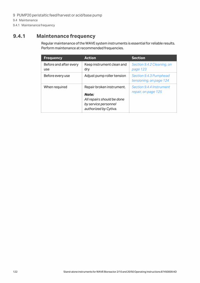
9.4.1 Maintenance frequencyRegular maintenance of the WAVE system instruments is essential for reliable results.Perform maintenance at recommended frequencies.
Frequency Action Section
Before and after everyuse
Keep instrument clean anddry
Section 9.4.2 Cleaning, onpage 123
Before every use Adjust pump roller tension Section 9.4.3 Pumpheadtensioning, on page 124
When required Repair broken instrument.
Note:All repairs should be doneby service personnelauthorized by Cytiva.
Section 9.4.4 Instrumentrepair, on page 125
9 PUMP20 peristaltic feed/harvest or acid/base pump9.4 Maintenance
9.4.1 Maintenance frequency
122 Stand-alone instruments for WAVE Bioreactor 2/10 and 20/50 Operating Instructions 87450009 AD

9.4.2 CleaningKeep the instruments dry and clean. The instruments must be turned off andunplugged before cleaning begins. Clean the exterior of the instruments with a dampcloth with water and, if required, alcohol. Do not use abrasive cleaners. Water shouldnot be applied directly to the instruments. Make sure that the instruments arecompletely dry before plugging them in.
9 PUMP20 peristaltic feed/harvest or acid/base pump9.4 Maintenance
9.4.2 Cleaning
Stand-alone instruments for WAVE Bioreactor 2/10 and 20/50 Operating Instructions 87450009 AD 123

9.4.3 Pumphead tensioning
CAUTIONPinch Hazard Make sure that the pump is switched off whenworking on the moving parts.
It is important that the pump roller tension be adjusted.
• If the tension is too low, then liquid will bypass the roller and the flow rate will be low.
• If the tension is too high then pump power will be wasted. There is also a risk ofwearing down the tubing during log time usage which will lead to rupture of thetubing.
The roller tension can be adjusted using a screwdriver. Adjust the spring tension androtate the pumphead by hand. The tubing should be completely squeezed as thepumphead rotates but must not require excessive effort to turn.
9 PUMP20 peristaltic feed/harvest or acid/base pump9.4 Maintenance
9.4.3 Pumphead tensioning
124 Stand-alone instruments for WAVE Bioreactor 2/10 and 20/50 Operating Instructions 87450009 AD

9.4.4 Instrument repairInstrument repair should only be done by service personnel authorized by Cytiva.
9 PUMP20 peristaltic feed/harvest or acid/base pump9.4 Maintenance
9.4.4 Instrument repair
Stand-alone instruments for WAVE Bioreactor 2/10 and 20/50 Operating Instructions 87450009 AD 125
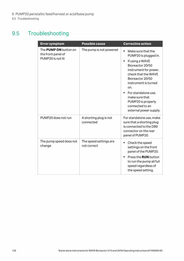
9.5 Troubleshooting
Error symptom Possible cause Corrective action
The PUMP ON button onthe front panel ofPUMP20 is not lit
The pump is not powered • Make sure that thePUMP20 is plugged in.
• If using a WAVEBioreactor 20/50instrument for power,check that the WAVEBioreactor 20/50instrument is turnedon.
• For standalone use,make sure thatPUMP20 is properlyconnected to anexternal power supply.
PUMP20 does not run A shorting plug is notconnected
For standalone use, makesure that a shorting plugis connected to the DB9connector on the rearpanel of PUMP20.
The pump speed does notchange
The speed settings arenot correct
• Check the speedsettings on the frontpanel of the PUMP20.
• Press the RUN buttonto run the pump all fullspeed regardless ofthe speed setting.
9 PUMP20 peristaltic feed/harvest or acid/base pump9.5 Troubleshooting
126 Stand-alone instruments for WAVE Bioreactor 2/10 and 20/50 Operating Instructions 87450009 AD

10 Reference information
This chapter contains technical data for the stand-alone instruments in this manual.
In this chapter
Section See page
10.1 Specifications 128
10.2 Recycling information 130
10.3 Regulatory information 131
10.4 Ordering information 136
10 Reference information
Stand-alone instruments for WAVE Bioreactor 2/10 and 20/50 Operating Instructions 87450009 AD 127

10.1 Specifications
DOOPT20
Parameter Value
Supply voltage 24 VDC through an adapter
(100 to 120 V ~ or 220 to 240 V ~,50 to 60 Hz)
Dimensions (h × w × d) 170 × 117 × 265 mm
Weight 1.5 kg
Operating temperature 4°C to 40°C
CO2MIX20 and CO2MIX20-R
Parameter Value
Supply voltage 24 VDC through an adapter
(100 to 120 V ~ or 220 to 240 V ~,50 to 60 Hz)
Dimensions (h × w × d) 200 × 320 × 170 mm
Weight 2.7 kg
Operating temperature 4°C to 40°C
Max pressure CO2 1 bar
Max air pressure 0.2 bar
O2MIX20 and O2MIX20-R
Parameter Value
Supply voltage 24 VDC through an adapter
(100 to 120 V ~ or 220 to 240 V ~,50 to 60 Hz)
Dimensions (h × w × d) 200 × 320 × 170 mm
Weight 2.7 kg
Operating temperature 4°C to 40°C
Max pressure O2 1 bar
Max air pressure 0.2 bar
10 Reference information10.1 Specifications
128 Stand-alone instruments for WAVE Bioreactor 2/10 and 20/50 Operating Instructions 87450009 AD

PUMP20
Parameter Value
Supply voltage 24 VDC through an adapter
(100 to 120 V ~ or 220 to 240 V ~,50 to 60 Hz)
Dimensions (h × w × d) 108 × 103 × 193 mm
Weight 1.0 kg
Operating temperature 4°C to 40°C
Power adapter
Parameter Value
Supply voltage 100 to 240 V ~, 47 to 63 Hz
Supply current Max 1.0 A
Output voltage 24 VDC +/- 5%
Output current Max 1.66 A
Power 40 W
Outlet Kycon 3 pin connector fir on 1.2 mshielded cable
(Pin 1 +, Pin 2 - and house to shield)
Dimensions (h × w × d) 34.5 × 52 × 118 mm
Operating temperature 4°C to 40°C
10 Reference information10.1 Specifications
Stand-alone instruments for WAVE Bioreactor 2/10 and 20/50 Operating Instructions 87450009 AD 129

10.2 Recycling information
DecontaminationThe product must be decontaminated before decommissioning. All local regulationsmust be followed with regard to scrapping of the equipment.
Disposal of the productWhen taking the product out of service, the different materials must be separated andrecycled according to national and local environmental regulations.
Recycling of hazardous substances
The product contains hazardous substances. Detailed information is available fromyour Cytiva representative.
Disposal of electrical components
Waste electrical and electronic equipment must not be disposed of as unsorted munic-ipal waste and must be collected separately. Please contact an authorized representa-tive of the manufacturer for information concerning the decommissioning of theequipment.
10 Reference information10.2 Recycling information
130 Stand-alone instruments for WAVE Bioreactor 2/10 and 20/50 Operating Instructions 87450009 AD
10.3 Regulatory information
IntroductionThis section lists the regulations and standards that apply to the product.
In this section
Section See page
10.3.1 Contact information 132
10.3.2 European Union and European Economic Area 133
10.3.3 Regulations for North America 134
10.3.4 Regulatory statements 135
10 Reference information10.3 Regulatory information
Stand-alone instruments for WAVE Bioreactor 2/10 and 20/50 Operating Instructions 87450009 AD 131

10.3.1 Contact information
Contact information for supportTo find local contact information for support and sending troubleshooting reports, visit cytiva.com/contact.
Manufacturing informationThe table below summarizes the required manufacturing information.
Requirement Information
Name and address of manufacturer Cytiva Sweden AB
Björkgatan 30
SE 751 84 Uppsala
Sweden
Telephone number of manufacturer + 46 771 400 600
10 Reference information10.3 Regulatory information
10.3.1 Contact information
132 Stand-alone instruments for WAVE Bioreactor 2/10 and 20/50 Operating Instructions 87450009 AD
10.3.2 European Union and European Economic Area
IntroductionThis section describes regulatory information for the European Union and EuropeanEconomic Area that applies to the equipment.
Conformity with EU DirectivesSee the EU Declaration of Conformity for the directives and regulations that apply forthe CE marking.
If not included with the product, a copy of the EU Declaration of Conformity is availableon request.
CE marking
The CE marking and the corresponding EU Declaration of Conformity is valid for theinstrument when it is:
• used according to the Operating Instructions or user manuals, and
• used in the same state as it was delivered, except for alterations described in theOperating Instructions or user manuals.
10 Reference information10.3 Regulatory information
10.3.2 European Union and European Economic Area
Stand-alone instruments for WAVE Bioreactor 2/10 and 20/50 Operating Instructions 87450009 AD 133

10.3.3 Regulations for North America
IntroductionThis section describes the information that applies to the product in the USA andCanada.
FCC complianceThis device complies with part 15 of the FCC Rules. Operation is subject to the followingtwo conditions: (1) This device may not cause harmful interference, and (2) this devicemust accept any interference received, including interference that may cause unde-sired operation.
Note: The user is cautioned that any changes or modifications not expresslyapproved by Cytiva could void the user’s authority to operate the equip-ment.
This equipment has been tested and found to comply with the limits for a Class A digitaldevice, pursuant to part 15 of the FCC Rules. These limits are designed to providereasonable protection against harmful interference when the equipment is operated ina commercial environment. This equipment generates, uses, and can radiate radiofrequency energy and, if not installed and used in accordance with the instructionmanual, may cause harmful interference to radio communications. Operation of thisequipment in a residential area is likely to cause harmful interference in which case theuser will be required to correct the interference at his own expense.
10 Reference information10.3 Regulatory information
10.3.3 Regulations for North America
134 Stand-alone instruments for WAVE Bioreactor 2/10 and 20/50 Operating Instructions 87450009 AD

10.3.4 Regulatory statements
IntroductionThis section shows regulatory statements that apply to regional requirements.
EMC emission, CISPR 11: Group 1,Class A statement
NOTICE
This equipment is not intended for use in residential environmentsand may not provide adequate protection to radio reception insuch environments.
Regulatory compliance of connectedequipment
Any equipment connected to WAVE Bioreactor stand-alone instruments should meetthe safety requirements of EN 61010-1/IEC61010-1 or relevant harmonized standards.Within the European Union, connected equipment must be CE-marked.
10 Reference information10.3 Regulatory information
10.3.4 Regulatory statements
Stand-alone instruments for WAVE Bioreactor 2/10 and 20/50 Operating Instructions 87450009 AD 135

10.4 Ordering informationFor ordering information, visit cytiva.com/wave.
10 Reference information10.4 Ordering information
136 Stand-alone instruments for WAVE Bioreactor 2/10 and 20/50 Operating Instructions 87450009 AD
Appendix A
Communications and data acquisition
In this chapter
Section See page
A.1 Overview 138
A.2 Analog/Alarm port 139
A.3 Analog signals 140
A.4 Alarm contact 141
A.5 Digital communication protocol 142
A.6 Communication wiring 143
A.7 Digital instrument addressing 145
A. Communications and data acquisition
Stand-alone instruments for WAVE Bioreactor 2/10 and 20/50 Operating Instructions 87450009 AD 137

A.1 OverviewTwo options for data communications are built into the stand-alone instruments:
1. ANALOG: The measured parameters are available on the back panel as voltagesfor driving chart recorders. These measurements are direct from adjusted sensorsand simplify validation as they are not digitally processed. In addition, a unit alarm isavailable on the back panel jack. This is a normally closed contact that will open ifany of the stand-alone instruments are in alarm. This is a dry contact output thatcan be used to interface to user alarm monitoring systems.
2. DIGITAL: Digital communication ports are provided on the back panel for RS-485multidrop data acquisition. The digital interface provides seamless interfacing withCytiva instrumentation and other WAVE Bioreactor instruments.
A. Communications and data acquisitionA.1 Overview
138 Stand-alone instruments for WAVE Bioreactor 2/10 and 20/50 Operating Instructions 87450009 AD

A.2 Analog/Alarm portA 8pin female mini-DIN jack on the back panel provides analog signals and the alarmcontact. Use a standard 8pin male mini-DIN cable to connect to this port.
A. Communications and data acquisitionA.2 Analog/Alarm port
Stand-alone instruments for WAVE Bioreactor 2/10 and 20/50 Operating Instructions 87450009 AD 139
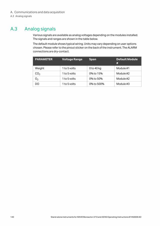
A.3 Analog signalsVarious signals are available as analog voltages depending on the modules installed.The signals and ranges are shown in the table below.
The default module shows typical wiring. Units may vary depending on user optionschosen. Please refer to the pinout sticker on the back of the instrument. The ALARMconnections are dry-contact.
PARAMETER Voltage Range Span Default Module#
Weight 1 to 5 volts 0 to 40 kg Module #1
CO2 1 to 5 volts 0% to 15% Module #2
O2 1 to 5 volts 0% to 50% Module #2
DO 1 to 5 volts 0% to 500% Module #3
A. Communications and data acquisitionA.3 Analog signals
140 Stand-alone instruments for WAVE Bioreactor 2/10 and 20/50 Operating Instructions 87450009 AD
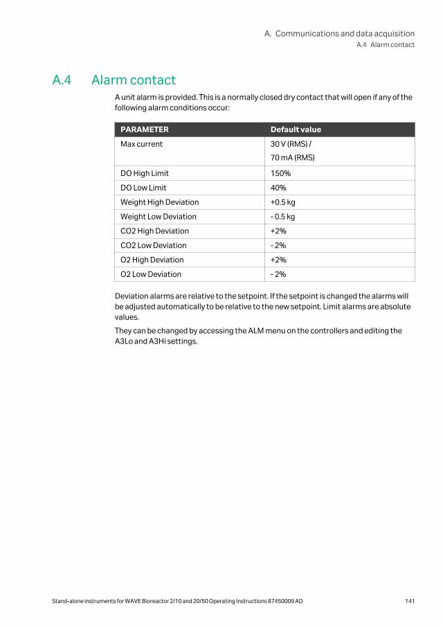
A.4 Alarm contactA unit alarm is provided. This is a normally closed dry contact that will open if any of thefollowing alarm conditions occur:
PARAMETER Default value
Max current 30 V (RMS) /
70 mA (RMS)
DO High Limit 150%
DO Low Limit 40%
Weight High Deviation +0.5 kg
Weight Low Deviation - 0.5 kg
CO2 High Deviation +2%
CO2 Low Deviation - 2%
O2 High Deviation +2%
O2 Low Deviation - 2%
Deviation alarms are relative to the setpoint. If the setpoint is changed the alarms willbe adjusted automatically to be relative to the new setpoint. Limit alarms are absolutevalues.
They can be changed by accessing the ALM menu on the controllers and editing theA3Lo and A3Hi settings.
A. Communications and data acquisitionA.4 Alarm contact
Stand-alone instruments for WAVE Bioreactor 2/10 and 20/50 Operating Instructions 87450009 AD 141

A.5 Digital communication protocolThere are two digital ports on the back panel. These are RJ11-6 telephone style jacks.Both jacks are wired internally in parallel to facilitate daisy-chain wiring. The communi-cations parameters are:
• 9600 baud
• No Parity
• 8 data bits
• 1 stop bit
The communication protocol used is standard MODBUS RTU.
A. Communications and data acquisitionA.5 Digital communication protocol
142 Stand-alone instruments for WAVE Bioreactor 2/10 and 20/50 Operating Instructions 87450009 AD

A.6 Communication wiringMultiple units and instruments may be daisy-chained together to form a RS-485network. Each standalone unit has two 6-pin RJ12 connectors for MODBUS located onthe rear panel. One cable is supplied with each standalone unit.
Converter 100
Additional unitsMODBUS RS485 daisy chain (2 parts provided with each unit)
WAVE Bioreactor DOOPT20 instrument
CO2MIX20
Connector labeled Primary or Secondary on the rear panel of Converter 100.
Note: Standalone units can not be used when a WAVEPOD II unit is connected tothe converter.
Daisychaining standalone unitsAdd another standalone unit to the chain by connecting a MODBUS cable between anRJ12 connector of one unit to an RJ12 connector of the next unit.
PC COM port
Standalone units
MODBUS cable pinoutOne cable is supplied with each standalone instrument.
A. Communications and data acquisitionA.6 Communication wiring
Stand-alone instruments for WAVE Bioreactor 2/10 and 20/50 Operating Instructions 87450009 AD 143

A. Communications and data acquisitionA.6 Communication wiring
144 Stand-alone instruments for WAVE Bioreactor 2/10 and 20/50 Operating Instructions 87450009 AD

A.7 Digital instrument addressingEach instrument on the RS-485 MODBUS link must be configured with a uniqueaddress from 1 to 247. The default addresses are:
DOOPT20 1
CO2MIX20 3
O2MIX20 7
AIRPUMP 81
BASE20/50EHT 101 Only in CO2MIX20 and O2MIX20
Several instruments may be connected to a single PC COM port by daisychaining. Allinstruments in the chain must have a unique address. The default address of a unit isthe same for all units of the same type.
• As long as there is only one instrument of a certain type in the chain, the defaultaddress need not be changed.
• If an instrument is to be added to the chain, and the chain already contains aninstrument of the same type, the default address of one of the units must bechanged.
Tag Address Location
DOOPT20 1 First DO instrument
DOOPT20-02 11 Second DO instrument
CO2MIX-01 3 First CO2 controller
CO2MIX-02 13 Second CO2 controller
Base20/50EHT 10 Third unit
If certain instruments are not present in your configuration, their addresses can be leftblank.
A. Communications and data acquisitionA.7 Digital instrument addressing
Stand-alone instruments for WAVE Bioreactor 2/10 and 20/50 Operating Instructions 87450009 AD 145

Appendix B
DOOPT20 measurement theory
In this chapter
Section See page
B.1 Introduction 147
B.2 Measurement theory 148
B.3 Effect of temperature 150
B.4 Measurement range 151
B.5 Cross-sensitivity 152
B.6 Response time 153
B.7 Stability 157
B. DOOPT20 measurement theory
146 Stand-alone instruments for WAVE Bioreactor 2/10 and 20/50 Operating Instructions 87450009 AD

B.1 IntroductionThe DOOPT20 is used to monitor dissolved oxygen (DO) levels in Cellbag bioreactors.
The DOOPT20 instrument uses an optical oxygen measurement DOOPT probe. Theprinciple of operation is based on the oxygen quenching of luminescence of dye mole-cules immobilized in the probe.
A quenching reaction occurs during excitation by sinusoidally modulated light. As aconsequence, there is a phase angle shift which can be measured and be correlated tothe amount of oxygen in the sample.
Figure 11.1: DOOPT20 Instrument Module
The major advantages of phase-angle based oxygen sensing over conventional Clark-type electrodes are:
1. No oxygen is consumed in the measurement
2. Fast response time (t90 < 10 s)
3. Can measure oxygen in gas or dissolved in liquids
4. Miniature size due to fiber optic technology
5. Long life with little drift
6. Not prone to drying out
In the WAVE Bioreactor application, the DOOPT-PROBE is used in the proven Oxywellconfiguration. The bare probe with its fast response time can be used for dynamicoxygen transfer measurements.
B. DOOPT20 measurement theoryB.1 Introduction
Stand-alone instruments for WAVE Bioreactor 2/10 and 20/50 Operating Instructions 87450009 AD 147

B.2 Measurement theoryThe DOOPT20 instrument measures the luminescence decay time of the immobilizedluminophore on the tip of the DOOPT-PROBE. The luminophore is typically a transitionmetal complex of Ruthenium. On excitation by incident light, the luminophore emitslight. In the presence of a quencher, such as molecular oxygen, the luminophorebecomes deactivated and does not emit light. A relationship exits between the oxygenconcentration in the sample and the luminescence intensity as well as the lumines-cence lifetime. This relationship is described in the Stern-Volmer equation:
τ = f([O2])
or
(τ0) ⁄ τ = 1 + Ksv[O2]
Where τ0 is the luminescence decay time in the absence of oxygen
τ is the luminescence decay time in the presence of oxygen
Ksv is the Stern-Volmer constant and depends on the immobilized dye
[O2] is the oxygen concentration
While it is possible to estimate the oxygen concentration by measuring the lumines-cence intensity, the results are not very reliable. The intensity varies with time as thesensor photobleaches. It is also sensitive to ambient light. In addition, the slope of theintensity response becomes quite shallow with oxygen concentrations greater the60% and this leads to very poor accuracy and reproducibility above this oxygenconcentration.
For these reasons, the DOOPT20 instrument does not use luminescence intensity inorder to estimate oxygen concentration. Instead, the luminescence decay time ismeasured using a phase-modulation technique. The luminophore is excited with sinus-oidally modulated light. The decay time of the luminophore causes a delay in theemitted light signal. This delay is manifested in a shift in the phase angle between theexcited and the emitted light signal. The amount of this phase shift is a function of theoxygen concentration as shown in the following equation:
τtan
2 fmodπ-------------------Φ - or tanΦ= = 2πfmod τ
where Φ is the phase angle and fmod the modulation frequency
Measurement of the phase shift has several advantages:
• Variations in the indicator dye luminescence or in the intensity of the light source donot effect the measurement.
• The decay time is not influenced by bending of the fiber or tip geometry.
• The measurement is not significantly influenced by the concentration of the dye.This reduces the impact of photobleaching and leaching of the dye.
• The decay time is not influenced by variations in the optical properties of the sampleincluding turbidity, refractive index and color.
B. DOOPT20 measurement theoryB.2 Measurement theory
148 Stand-alone instruments for WAVE Bioreactor 2/10 and 20/50 Operating Instructions 87450009 AD

The oxygen measurement is reported at % of air saturation. Air is referenced to 20.95%oxygen, which corresponds to 100% saturation. Since the Stern-Volmer equation ishighly non-linear, appropriate linearization calculations are performed by the micro-processor inside the DOOPT20 instrument.
Water vapor influences the oxygen partial pressure in air and for most accurate results,the probe calibration should be made in air-saturated water or water-saturated air.
B. DOOPT20 measurement theoryB.2 Measurement theory
Stand-alone instruments for WAVE Bioreactor 2/10 and 20/50 Operating Instructions 87450009 AD 149

B.3 Effect of temperatureTemperature affects the luminescence decay time as well as the intensity. The diffu-sion of oxygen is greater at higher temperatures and this also causes variations.
In addition, solubility of oxygen in water is temperature dependent and can bedescribed by Henry’s law.
B. DOOPT20 measurement theoryB.3 Effect of temperature
150 Stand-alone instruments for WAVE Bioreactor 2/10 and 20/50 Operating Instructions 87450009 AD
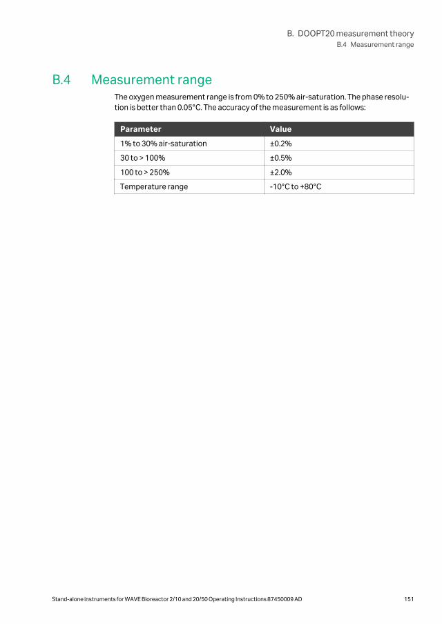
B.4 Measurement rangeThe oxygen measurement range is from 0% to 250% air-saturation. The phase resolu-tion is better than 0.05°C. The accuracy of the measurement is as follows:
Parameter Value
1% to 30% air-saturation ±0.2%
30 to > 100% ±0.5%
100 to > 250% ±2.0%
Temperature range -10°C to +80°C
B. DOOPT20 measurement theoryB.4 Measurement range
Stand-alone instruments for WAVE Bioreactor 2/10 and 20/50 Operating Instructions 87450009 AD 151

B.5 Cross-sensitivityThere is no cross sensitivity for CO2. Increasing the salt (chloride) concentrationdecreases the solubility of oxygen. This is why it is best to readjust the 100% point inthe actual culture fluid (in Oxywell2) once the system temperature has equilibrated.Physiological saline is used in the Oxywell2 to minimize any salt concentration arti-facts.
B. DOOPT20 measurement theoryB.5 Cross-sensitivity
152 Stand-alone instruments for WAVE Bioreactor 2/10 and 20/50 Operating Instructions 87450009 AD

B.6 Response time
In this section
Section See page
B.6.1 Bare probe 154
B.6.2 Wet Oxywell2 155
B.6.3 Dry Oxywell2 156
B. DOOPT20 measurement theoryB.6 Response time
Stand-alone instruments for WAVE Bioreactor 2/10 and 20/50 Operating Instructions 87450009 AD 153

B.6.1 Bare probeThe bare probe has a response time (t90) of about 4 to 5 seconds. The graph belowshows the response going from air saturation to 0% oxygen solution.
The graph below shows the response time going from 0% oxygen to air saturation. Theresponse time (t90) is about the same (4 to 5 seconds).
B. DOOPT20 measurement theoryB.6 Response time
B.6.1 Bare probe
154 Stand-alone instruments for WAVE Bioreactor 2/10 and 20/50 Operating Instructions 87450009 AD

B.6.2 Wet Oxywell2The response time (t90) in the filled Oxywell2 is about 2 to 3 minutes as shown in thefollowing graph:
B. DOOPT20 measurement theoryB.6 Response time
B.6.2 Wet Oxywell2
Stand-alone instruments for WAVE Bioreactor 2/10 and 20/50 Operating Instructions 87450009 AD 155

B.6.3 Dry Oxywell2
In a dry Oxywell2 the response time is quite long due to the relatively large amount ofstagnant air in the tip that must diffuse through the silicone. The response time (t90)can range from 5 to 6 minutes as shown in the graph below.
Note: Use of a dry Oxywell2 for oxygen monitoring in Cellbag bioreactors is notrecommended.
B. DOOPT20 measurement theoryB.6 Response time
B.6.3 Dry Oxywell2
156 Stand-alone instruments for WAVE Bioreactor 2/10 and 20/50 Operating Instructions 87450009 AD

B.7 StabilityFor long term stability, the probe is only illuminated intermittently. The defaultsampling frequency is every 10 seconds. The sampling frequency can be changed fordynamic measurements to as high as once per second.
The drift due to photo-bleaching is < 0.6% air-saturation per 100,000 measurements.At 10 second sampling this corresponds to 10 days. The Oxywell2 device permits reca-libration of the probe without risk of contamination.
B. DOOPT20 measurement theoryB.7 Stability
Stand-alone instruments for WAVE Bioreactor 2/10 and 20/50 Operating Instructions 87450009 AD 157

cytiva.com
Cytiva and the Drop logo are trademarks of Global Life Sciences IP Holdco LLC or an affiliate.
Cellbag, WAVE Bioreactor, and WAVE are trademarks of Global Life Sciences Solutions USA LLC or an affiliate doing business asCytiva.
All other third-party trademarks are the property of their respective owners.
© 2020–2021 Cytiva
All goods and services are sold subject to the terms and conditions of sale of the supplying company operating within the Cytivabusiness. A copy of those terms and conditions is available on request. Contact your local Cytiva representative for the most currentinformation.
For local office contact information, visit cytiva.com/contact
87450009 AD V:5 05/2021