Embed Size (px)
Citation preview
1
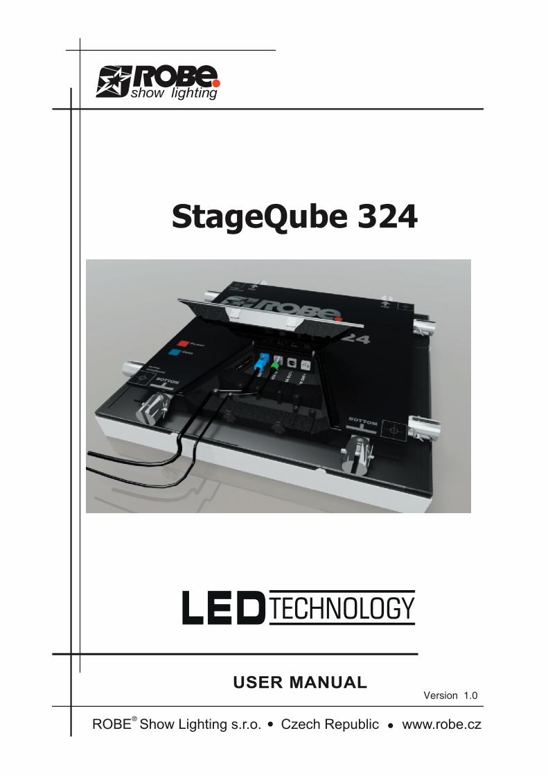
Version 1.0
2 3
Table of contents1. Safety instructions ......................................................................................................... 32. Operating and structural requirements........................................................................ 3
2.1 Operating determinations........................................................................................... 32.2 Structural requirements.............................................................................................. 4
2.2.1.0 StageQube, BlindQube Without LEDs, BlindQube- Expo, StageQube- Floor Unit..... 42.2.1.1 Unsupported Type Combined with StageQube- Floor Unit (max. 5 modules) ............ 42.2.1.2 Suspended Type (max. 12 modules).............................................................................. 42.2.2.0 BlindQube-Mediaadapter .............................................................................................. 42.2.2.1 Suspended Type (Without Abutment)............................................................................ 42.2.2.2 Vertical Suspended Type with Abutment....................................................................... 52.2.2.3 Diagram for 2.2 Vertical Suspended Type with Abutment ............................................ 5
3. Description of the fixture............................................................................................... 53.1 Back side.................................................................................................................... 53.2 Hadling ....................................................................................................................... 53.3 Maintenance............................................................................................................... 63.4 Cleaning ..................................................................................................................... 6
4. Installation....................................................................................................................... 64.1 Connecting to the mains ............................................................................................ 64.2 Rigging the fixture ..................................................................................................... 6
4.2.2 Hanging a StageQube324 array from a truss .................................................... 74.2.3 Setting up the fixtures on the floor ..................................................................... 8
4.3 Power connection between StageQube324s ............................................................. 84.4 Data connection ......................................................................................................... 84.5 Setting up the QubeControl software ......................................................................... 9
4.5.1 PREREQUISITES ..........................................................................................94.5.2 VIDEO GRABBING CAPABILITIES .............................................................94.5.3 QUBECONTROL SOFTWARE INSTALLATION............................................9
5. WORKING WITH A STAGEQUBE 324 ARRAY ........................................................... 115.1 Starting the software ................................................................................................ 115.2 FINDING THE STAGEQUBE 324........................................................................ 115.3 ARRAY CONFIGURATION ................................................................................. 125.4 USING QUBECONTROL..................................................................................... 155.5 EXPLANATION OF THE SCREEN AREAS AND THEIR FUNCTIONALITY ..... 15
5.5.1 Source Selection .............................................................................................. 15
StageQube 324

2 3
5.5.2 Frame parameters............................................................................................ 165.5.3 Realtime Parameters ....................................................................................... 165.5.4 Preview ............................................................................................................ 165.5.5 Media Player .................................................................................................... 175.5.6 VGA-In and Test .............................................................................................. 175.5.7 Qube Layout..................................................................................................... 17
6. Technical specifications.............................................................................................. 17
4 5
CAUTION!Keep this device away from rain and moisture!Unplug mains lead before opening the housing!
FOR YOUR OWN SAFETY, PLEASE READ THIS USER MANUAL CAREFULLY BEFORE YOU INITIAL START - UP!
1. Safety instructionsEvery person involved with installation and maintenance of this device have to:- be qualilfied- follow the instructions of this manual
CAUTION! Be careful with your operations.
With a high voltage you can suffera dangerous electric shock when touching the wires!
This device has left our premises in absolutely perfect condition. In order to maintain this condition and to en-sure a safe operation, it is absolutely necessary for the user to follow the safety instructions and warning notes written in this manual.
Important:The manufacturer will not accept liability for any resulting damages caused by the non-observance of this manual or any unauthorized modification to the device.Please consider that damages caused by manual modifications to the device are not subject to warranty.
Never let the power-cord come into contact with other cables! Handle the power-cord and all connections with mains with particular caution!
Make sure that the available voltage is not higher than stated on the rear panel.Always plug in the power plug last. The power-plug has to be accessible after installing the device.
Make sure that the power cord is never crimped or damaged by sharp edges. Check the device and the power cord from time to time.
Always disconnect from the mains when the device is not in use or before cleaning it. Only handle the power--cord by the plug. Never pull out the plug by tugging the power-cord.
The electric connection, repairs and servicing must be carried out by a qualified employee.
Do not connect this device to a dimmer pack.
2. Operating and structural requirements
2.1 Operating determinationsIf the device has been exposed to drastic temperature fluctuation (e.g. after transportation), do not switch it on immediately. The arising condensation water might damage your device. Leave the device switched off until it has reached room temperature.
Do not shake the device. Avoid brute force when installing or operating the device. NEVER place the fixture on the ground with the LED – side down.
When carrying the fixture, always use the fork connectors at the sides. They work well as handles. Don’t grab the fixture by the diffusor.
4 5
Make sure that the area below the installation place is blocked when rigging, derigging or servicing the fix-
ture.Only operate the fixture after having checked that the housing is firmly closed and all screws are tightly faste-ned.
Operate the device only after having familiarized with its functions. Do not permit operation by persons not qualified for operating the device. Most damages are the result of unprofessional operation!
Please use the original packaging if the device is to be transported.
Please consider that unauthorized modifications on the device are forbidden due to safety reasons!
If this device will be operated in any way different to the one described in this manual, the product may suffer damages and the guarantee becomes void. Furthermore, any other operation may lead to dangers like short-circuit, burns, electric shock, burns due to ultraviolet radiation, lamp explosion, crash etc.
The fixture has got an IP rating of IP54. Be aware that the IP54 is dependent on the correct orientation.
2.2 Structural requirements
Structural Requirements to StageQube and Accessories (BlindQube– Without LEDs, BlindQube-Expo, StageQube- Floor Unit)
The modules are adequately capable of bearing loads, if the following conditions areobserved: In general: for indoor operation only. taper pins, property class 5.6. after driving in of the taper pins, they shall be fixed with cotter pins.
2.2.1.0 StageQube, BlindQube Without LEDs, BlindQube- Expo, StageQube- Floor Unit
2.2.1.1 Unsupported Type Combined with StageQube- Floor Unit (max. 5 modules) - diagonal tubes as sectional tubes RR RR 50x2 AlMgSi 0,5 F22. - In case of possible impact with a person, a ballast with a weight of 150 kg shall be placed between the bottom ends of each gap of the erected system. - In case impacts can be excluded, ballast with a weight of 20 kg are required.
2.2.1.2 Suspended Type (max. 12 modules)- the annular lug must have been approved to bear loads of 350 kg by the manufacturer. - all suspension points shall be designed for load actions of 1.74 kN.- dynamic lifting forces and downward motions as a result of elastic materials shall be considered for the suspension points.
2.2.2.0 BlindQube-Mediaadapter
2.2.2.1 Suspended Type (Without Abutment)
BGVC1 (for passenger traffic) max. 3 modules DIN 4113 (without passenger traffic) max. 6 modules- the annular lug must have been approved to bear loads of 330 kg by the manufacturer. - all suspension points shall be designed for load actions of 1.65 kN.- dynamic lifting forces and downward motions as a result of elastic materials shall be considered for the suspension points.- max. 45 kg at each Qube at a distance of 47 cm. - the max. quantity mainly depends on the weight of the moving lights. reduced loads will allow for higher quantities. This requires exact static calculation
6 7
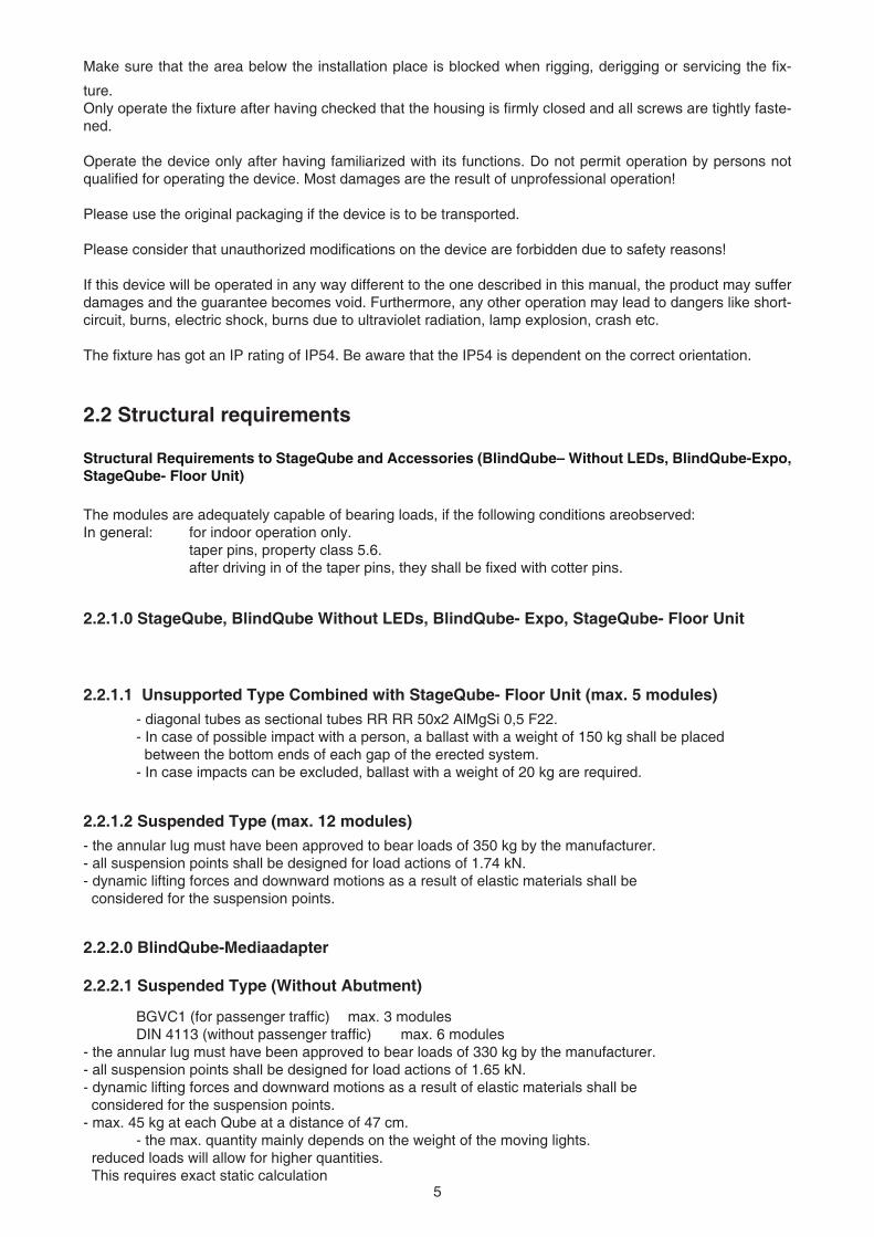
2.2.2.2 Vertical Suspended Type with Abutment- the annular lug must have been approved to bear loads of 330 kg by the manufacturer. - all suspension points shall be designed for load actions of 1.65 kN.- dynamic lifting forces and downward motions as a result of elastic materials shall be considered for the suspension points.- max. 45 kg at each cube at a distance of 47 cm.- depending on the number of blind cubes, a certain number of stage cubes will be approved. (see diagram) - the max. quantity mainly depends on the weight of the moving lights. reduced loads will allow for higher quantities. This requires exact static calculation.
2.2.2.3 Diagram for 2.2 Vertical Suspended Type with Abutment
number of BlindQubes number of StageQube324s Guidelines2 12 BGV C13 7 BGV C14 12 DIN 41135 12 DIN 41136 10 DIN 4113
3. Description of the fixture
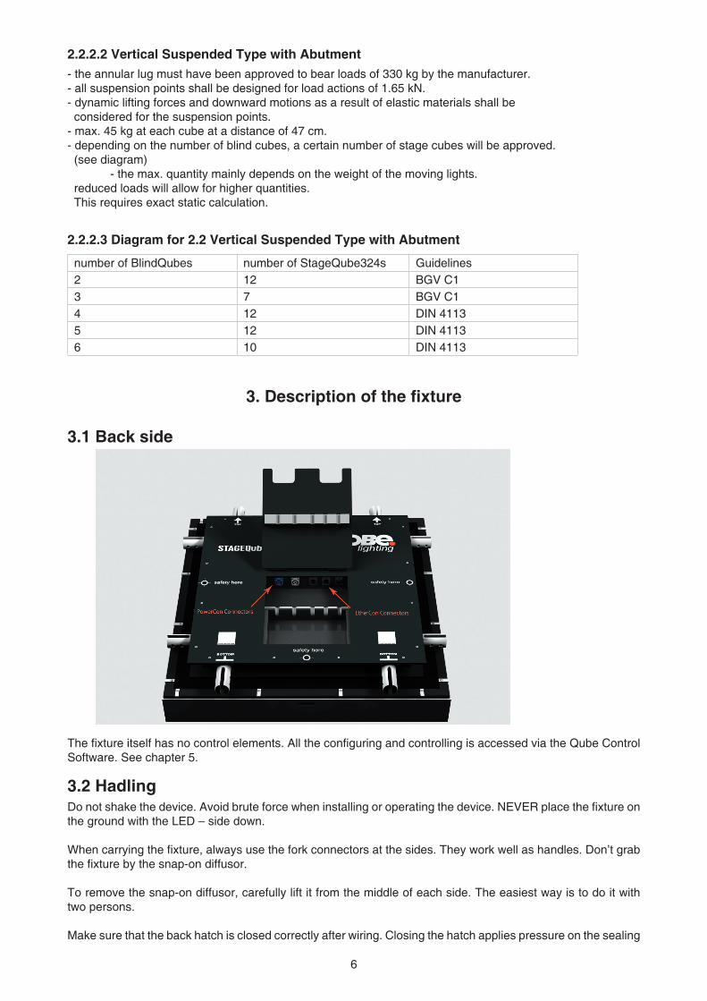
3.1 Back side
The fixture itself has no control elements. All the configuring and controlling is accessed via the Qube Control Software. See chapter 5.
3.2 HadlingDo not shake the device. Avoid brute force when installing or operating the device. NEVER place the fixture on the ground with the LED – side down.
When carrying the fixture, always use the fork connectors at the sides. They work well as handles. Don’t grab the fixture by the snap-on diffusor.
To remove the snap-on diffusor, carefully lift it from the middle of each side. The easiest way is to do it with two persons.
Make sure that the back hatch is closed correctly after wiring. Closing the hatch applies pressure on the sealing
6 7
gasket inside and thus prevents water from coming in. Be careful that the cables lie in their dedicated place.
3.3 MaintenanceThe fixture needs no technical maintenance.
3.4 CleaningUse only warm water and low concentrated soap-lotion to clean the housing. Do not apply any cleaners on both the clear and the diffusion covers, especially NO GLASS CLEANERS. Use a soft cloth for cleaning.
4. Installation
4.1 Connecting to the mains
The built-in power supply unit adjusts automatically in a range of 110 V – 240 V @ 50 Hz – 60 Hz. Verify the power source is in that range before applying power!
Install a 3-prong grounding-type plug on the power cable. The earth has to be connected!Only use a Neutrik PowerCon™ NAC3FCA connector for the power supply.If you have any doubts about proper installation, consult a qualified electrician.
4.2 Rigging the fixture
DENGER TO LIFEPlease consider the respective national norms during the installation. The installation
must only be carried out by an authorized distributor!
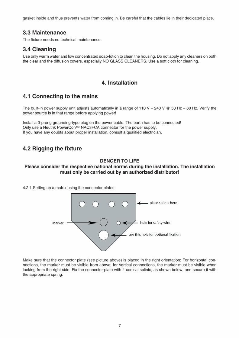
4.2.1 Setting up a matrix using the connector plates
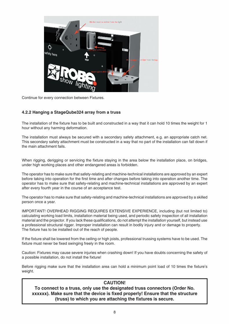
Make sure that the connector plate (see picture above) is placed in the right orientation: For horizontal con-nections, the marker must be visible from above; for vertical connections, the marker must be visible when looking from the right side. Fix the connector plate with 4 conical splints, as shown below, and secure it with the appropriate spring.
8 9
Continue for every connection between Fixtures.
4.2.2 Hanging a StageQube324 array from a truss
The installation of the fixture has to be built and constructed in a way that it can hold 10 times the weight for 1 hour without any harming deformation.
The installation must always be secured with a secondary safety attachment, e.g. an appropriate catch net. This secondary safety attachment must be constructed in a way that no part of the installation can fall down if the main attachment fails.
When rigging, derigging or servicing the fixture staying in the area below the installation place, on bridges, under high working places and other endangered areas is forbidden.
The operator has to make sure that safety-relating and machine-technical installations are approved by an expert before taking into operation for the first time and after changes before taking into operation another time. The operator has to make sure that safety-relating and machine-technical installations are approved by an expert after every fourth year in the course of an acceptance test.
The operator has to make sure that safety-relating and machine-technical installations are approved by a skilled person once a year.
IMPORTANT! OVERHEAD RIGGING REQUIRES EXTENSIVE EXPERIENCE, including (but not limited to) calculating working load limits, installation material being used, and periodic safety inspection of all installation material and the projector. If you lack these qualifications, do not attempt the installation yourself, but instead use a professional structural rigger. Improper installation can result in bodily injury and or damage to property. The fixture has to be installed out of the reach of people.
If the fixture shall be lowered from the ceiling or high joists, professional trussing systems have to be used. The fixture must never be fixed swinging freely in the room.
Caution: Fixtures may cause severe injuries when crashing down! If you have doubts concerning the safety of a possible installation, do not install the fixture!
Before rigging make sure that the installation area can hold a minimum point load of 10 times the fixture’s weight.
CAUTION!To connect to a truss, only use the designated truss connectors (Order No.
xxxxxx). Make sure that the device is fixed properly! Ensure that the structure(truss) to which you are attaching the fixtures is secure.
8 9
When connecting an array of StageQube324s to a truss, make sure the topmostfixture of EVERY column is properly attached to the truss.
A maximum number of 12 StageQube324 can be hung from a truss one upon the other.
DANGER TO LIFE! Before taking into operation for the first time, the installation has to be approved by an expert!
4.2.3 Setting up the fixtures on the floorUse only the dedicated foot plates to set up an array on the floor. The standard foot plate can carry up to 3 StageQube324 without an outrigger. With the optional foot plate with outrigger, it is possible to staple up to 5 StageQube324. This is valid only for indoor use. If you intend to use StageQube324 with foot plates outdoors, you must consider the wind load! Every outdoor installation must be verified by a specialist!
4.3 Power connection between StageQube324sThe StageQube324 is equipped with two Neutrik™ PowerCon™ sockets. You can interconnect up to 8 Stage-Qube324 units using the PowerCon™ connection cables. Never connect more than 8 StageQube324 to one single power supply line.
4.4 Data connectionThe StageQube324 is equipped with 3 Neutrik™ EtherCon™ sockets. With this feature it is possible to build up tree like structures for the Ethernet wiring.
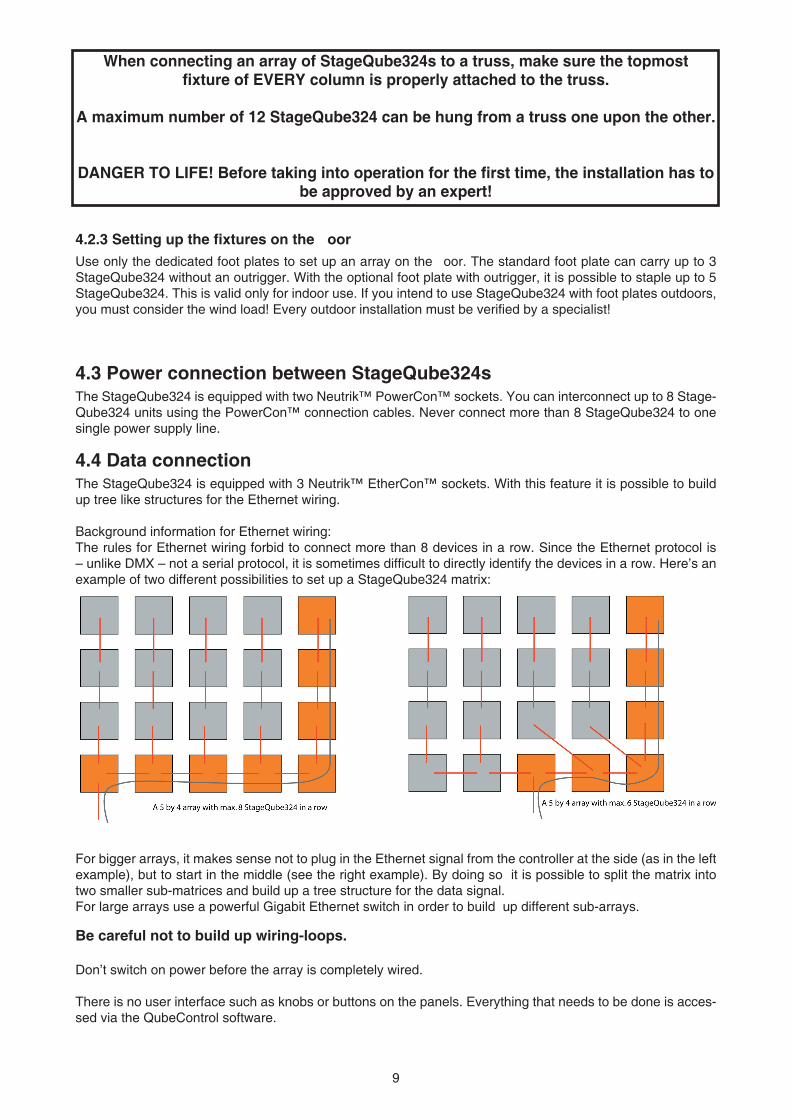
Background information for Ethernet wiring:The rules for Ethernet wiring forbid to connect more than 8 devices in a row. Since the Ethernet protocol is – unlike DMX – not a serial protocol, it is sometimes difficult to directly identify the devices in a row. Here’s an example of two different possibilities to set up a StageQube324 matrix:
For bigger arrays, it makes sense not to plug in the Ethernet signal from the controller at the side (as in the left example), but to start in the middle (see the right example). By doing so it is possible to split the matrix into two smaller sub-matrices and build up a tree structure for the data signal. For large arrays use a powerful Gigabit Ethernet switch in order to build up different sub-arrays.
Be careful not to build up wiring-loops.
Don’t switch on power before the array is completely wired.
There is no user interface such as knobs or buttons on the panels. Everything that needs to be done is acces-sed via the QubeControl software.
10 11
4.5 Setting up the QubeControl software
4.5.1 PREREQUISITES
-Required operating system is Windows XP professional with Service Pack 2 installed -Make sure that no virtualization software (such as VMWare) is running on your system. -If your computer possesses more than one Ethernet port, make sure that only one of them is used. -Make sure that no DHCP server is running in your PC or in the network, especially when using (managed) switches. The QubeControl software starts its own DHCP server when running. -Make sure that no other computers are connected to the StageQube-Network (they may eat up the IP-addresses needed for the StageQube324s).
4.5.2 VIDEO GRABBING CAPABILITIES -VGA grabbing is supported with a specifi c capture card: the Single-channel Phynx RGB card manufactured by EMS-Imaging. Other VGA capture cards are not supported. Background information: this card has been chosen because it does a lot of the video work directly on the card and thus relieves the Main CPU for its main purpose: the distribution of the data to the StageQube324 array.
The capture card must be installed properly. For further information please consult the manufacturer’s ma-nual.
4.5.3 QUBECONTROL SOFTWARE INSTALLATION -Please uninstall all previous versions of the QubeControl software (use the Windows Control Panel --> Software) and delete all remaining links which you may have (e.g. on the desktop) before installing the software.- The application is designed to work with a resolution of 1280 x 1024 px at 24 or 32 Bits color depth. Please ensure the correct setting of your computer display by selecting the display properties from the system’s Control Panel. - Network settings: The computer which runs the QubeControl software needs a dedicated IP address. IMPORTANT: Please set the IP address to
172.16.5.0 and its subnet-mask to
255.255.0.0.For further information on how to modify the network settings, use the windows help fi les.
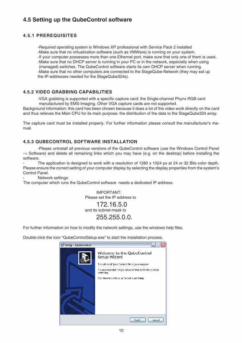
Double-click the icon “QubeControlSetup.exe” to start the installation process.
10 11
Follow the instructions on the screen.
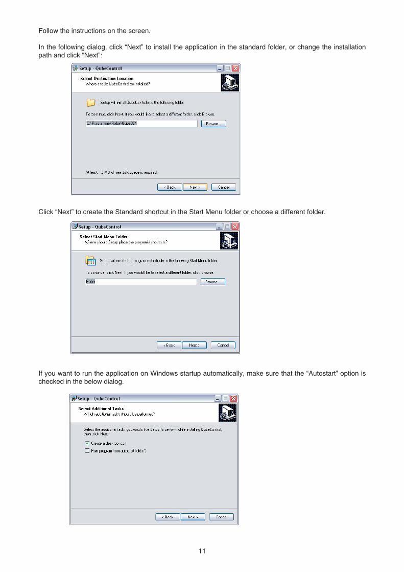
In the following dialog, click “Next” to install the application in the standard folder, or change the installation path and click “Next”:
Click “Next” to create the Standard shortcut in the Start Menu folder or choose a different folder.
If you want to run the application on Windows startup automatically, make sure that the “Autostart” option is checked in the below dialog.
12 13
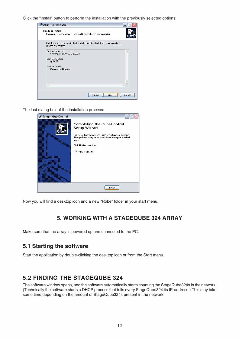
Click the “Install” button to perform the installation with the previously selected options:
The last dialog box of the installation process:
Now you will fi nd a desktop icon and a new “Robe” folder in your start menu.
5. WORKING WITH A STAGEQUBE 324 ARRAY
Make sure that the array is powered up and connected to the PC.
5.1 Starting the softwareStart the application by double-clicking the desktop icon or from the Start menu.
5.2 FINDING THE STAGEQUBE 324The software window opens, and the software automatically starts counting the StageQube324s in the network. (Technically the software starts a DHCP process that tells every StageQube324 its IP-address.) This may take some time depending on the amount of StageQube324s present in the network.
12 13
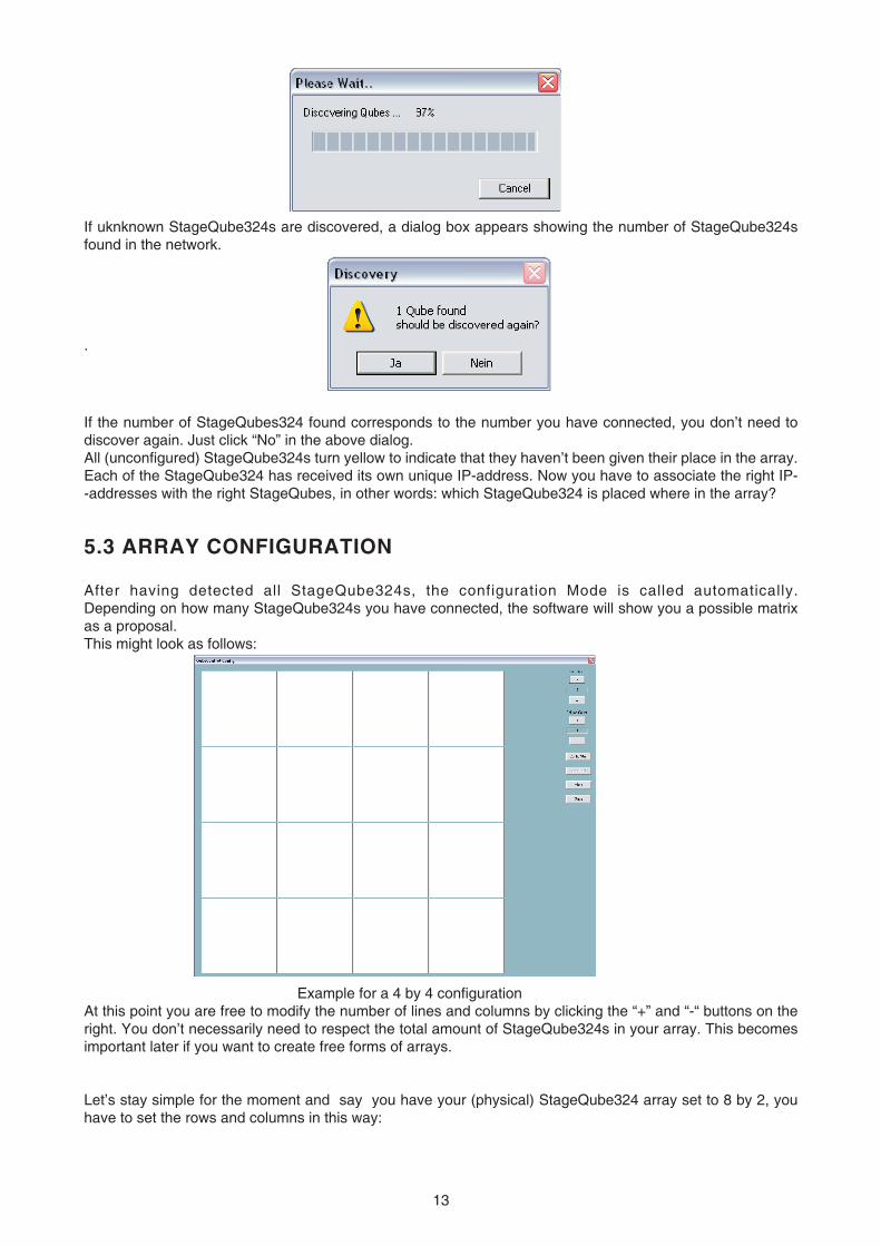
If uknknown StageQube324s are discovered, a dialog box appears showing the number of StageQube324s found in the network.
.
If the number of StageQubes324 found corresponds to the number you have connected, you don’t need to discover again. Just click “No” in the above dialog.All (unconfi gured) StageQube324s turn yellow to indicate that they haven’t been given their place in the array. Each of the StageQube324 has received its own unique IP-address. Now you have to associate the right IP--addresses with the right StageQubes, in other words: which StageQube324 is placed where in the array?
5.3 ARRAY CONFIGURATION
After having detected all StageQube324s, the configuration Mode is called automatically. Depending on how many StageQube324s you have connected, the software will show you a possible matrix as a proposal.This might look as follows:
Example for a 4 by 4 confi gurationAt this point you are free to modify the number of lines and columns by clicking the “+” and “-“ buttons on the right. You don’t necessarily need to respect the total amount of StageQube324s in your array. This becomes important later if you want to create free forms of arrays.
Let’s stay simple for the moment and say you have your (physical) StageQube324 array set to 8 by 2, you have to set the rows and columns in this way:
14 15
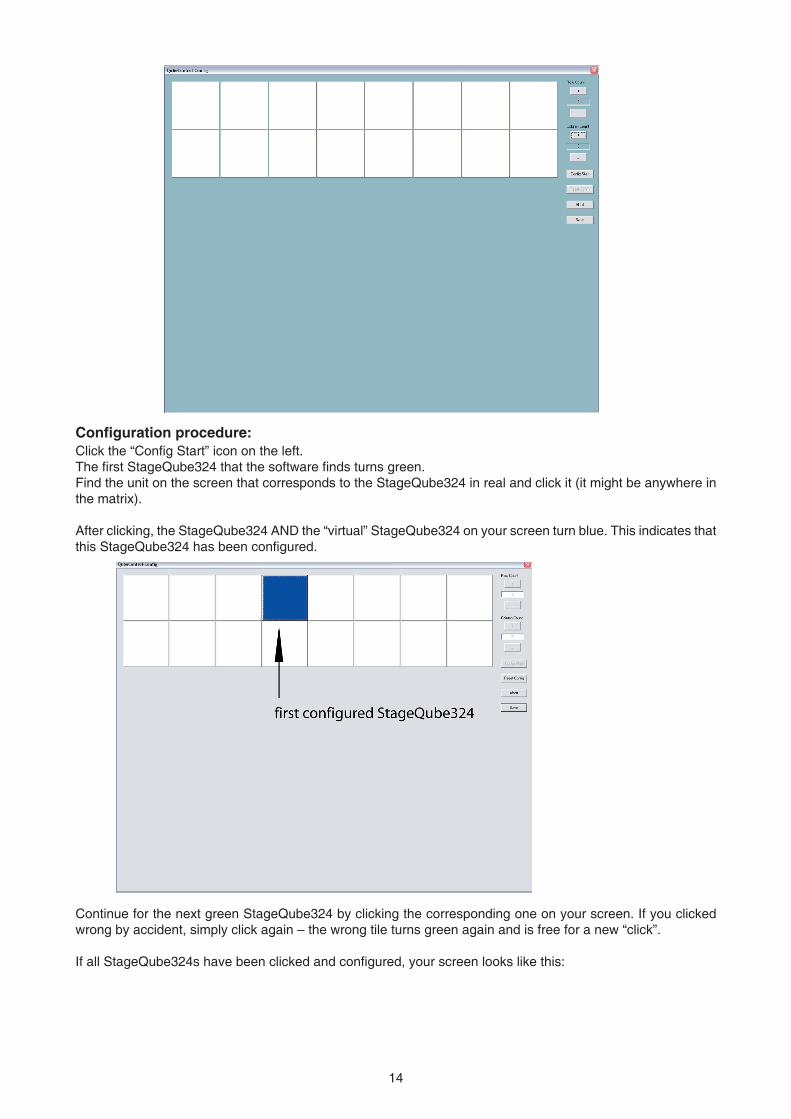
Confi guration procedure:Click the “Confi g Start” icon on the left.The fi rst StageQube324 that the software fi nds turns green.Find the unit on the screen that corresponds to the StageQube324 in real and click it (it might be anywhere in the matrix).
After clicking, the StageQube324 AND the “virtual” StageQube324 on your screen turn blue. This indicates that this StageQube324 has been confi gured.
Continue for the next green StageQube324 by clicking the corresponding one on your screen. If you clicked wrong by accident, simply click again – the wrong tile turns green again and is free for a new “click”. If all StageQube324s have been clicked and confi gured, your screen looks like this:
14 15
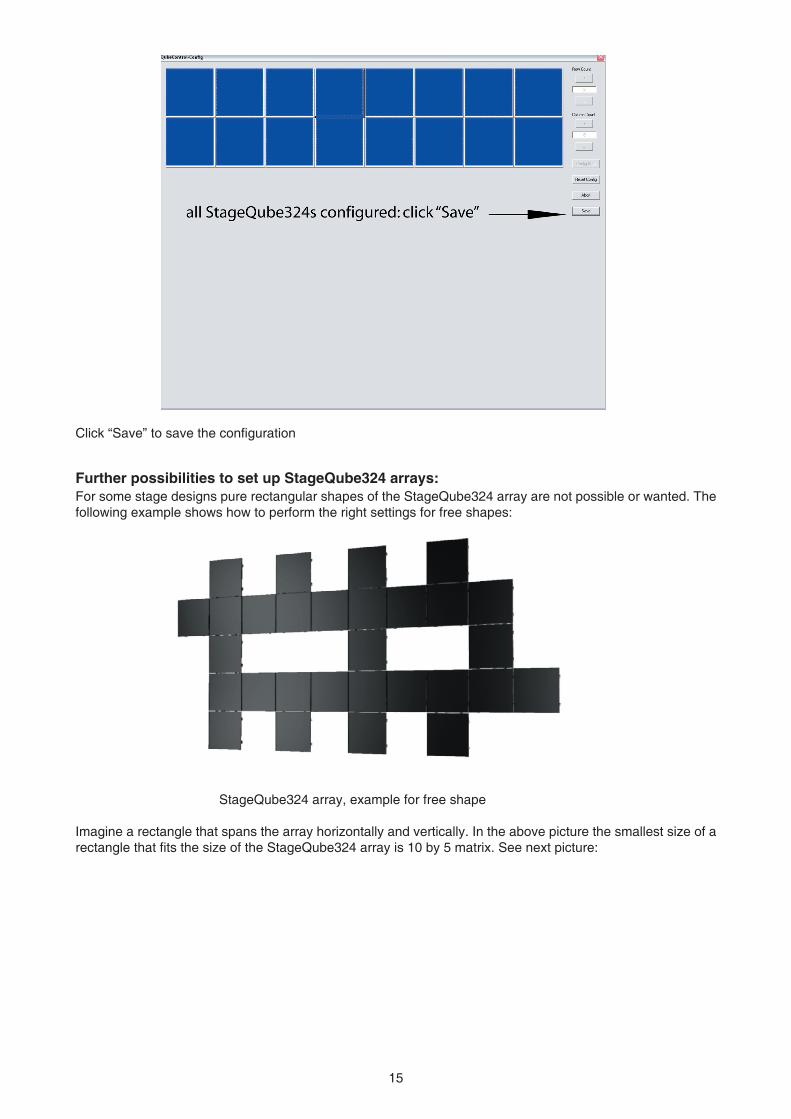
Click “Save” to save the confi guration
Further possibilities to set up StageQube324 arrays:For some stage designs pure rectangular shapes of the StageQube324 array are not possible or wanted. The following example shows how to perform the right settings for free shapes:
StageQube324 array, example for free shape
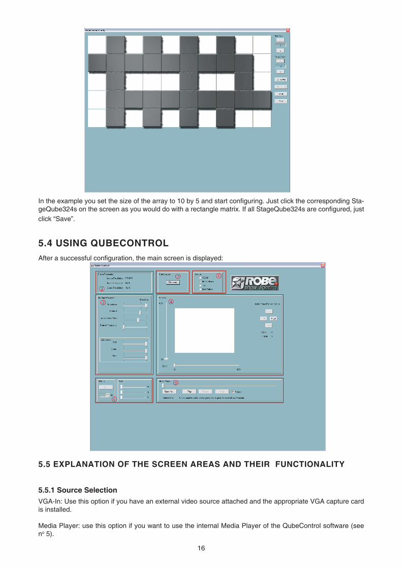
Imagine a rectangle that spans the array horizontally and vertically. In the above picture the smallest size of a rectangle that fi ts the size of the StageQube324 array is 10 by 5 matrix. See next picture:
16 17
In the example you set the size of the array to 10 by 5 and start confi guring. Just click the corresponding Sta-geQube324s on the screen as you would do with a rectangle matrix. If all StageQube324s are confi gured, just click “Save”.
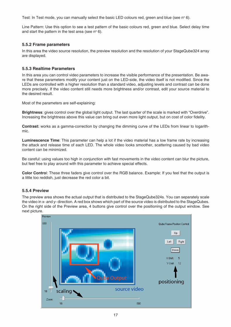
5.4 USING QUBECONTROLAfter a successful confi guration, the main screen is displayed:
5.5 EXPLANATION OF THE SCREEN AREAS AND THEIR FUNCTIONALITY
5.5.1 Source SelectionVGA-In: Use this option if you have an external video source attached and the appropriate VGA capture card is installed.
Media Player: use this option if you want to use the internal Media Player of the QubeControl software (see no 5).
16 17
Test: In Test mode, you can manually select the basic LED colours red, green and blue (see no 6).
Line Pattern: Use this option to see a test pattern of the basic colours red, green and blue. Select delay time and start the pattern in the test area (see no 6).
5.5.2 Frame parametersIn this area the video source resolution, the preview resolution and the resolution of your StageQube324 array are displayed.
5.5.3 Realtime ParametersIn this area you can control video parameters to increase the visible performance of the presentation. Be awa-re that these parameters modify your content just on the LED-side, the video itself is not modified. Since the LEDs are controlled with a higher resolution than a standard video, adjusting levels and contrast can be done more precisely. If the video content still needs more brightness and/or contrast, edit your source material to the desired result.
Most of the parameters are self-explaining:
Brightness: gives control over the global light output. The last quarter of the scale is marked with “Overdrive”. Increasing the brightness above this value can bring out even more light output, but on cost of color fidelity.
Contrast: works as a gamma-correction by changing the dimming curve of the LEDs from linear to logarith-mic.
Luminescence Time: This parameter can help a lot if the video material has a low frame rate by increasing the attack and release time of each LED. The whole video looks smoother, scattering caused by bad video content can be minimized.
Be careful: using values too high in conjunction with fast movements in the video content can blur the picture, but feel free to play around with this parameter to achieve special effects.
Color Control: These three faders give control over the RGB balance. Example: If you feel that the output is a little too reddish, just decrease the red color a bit.
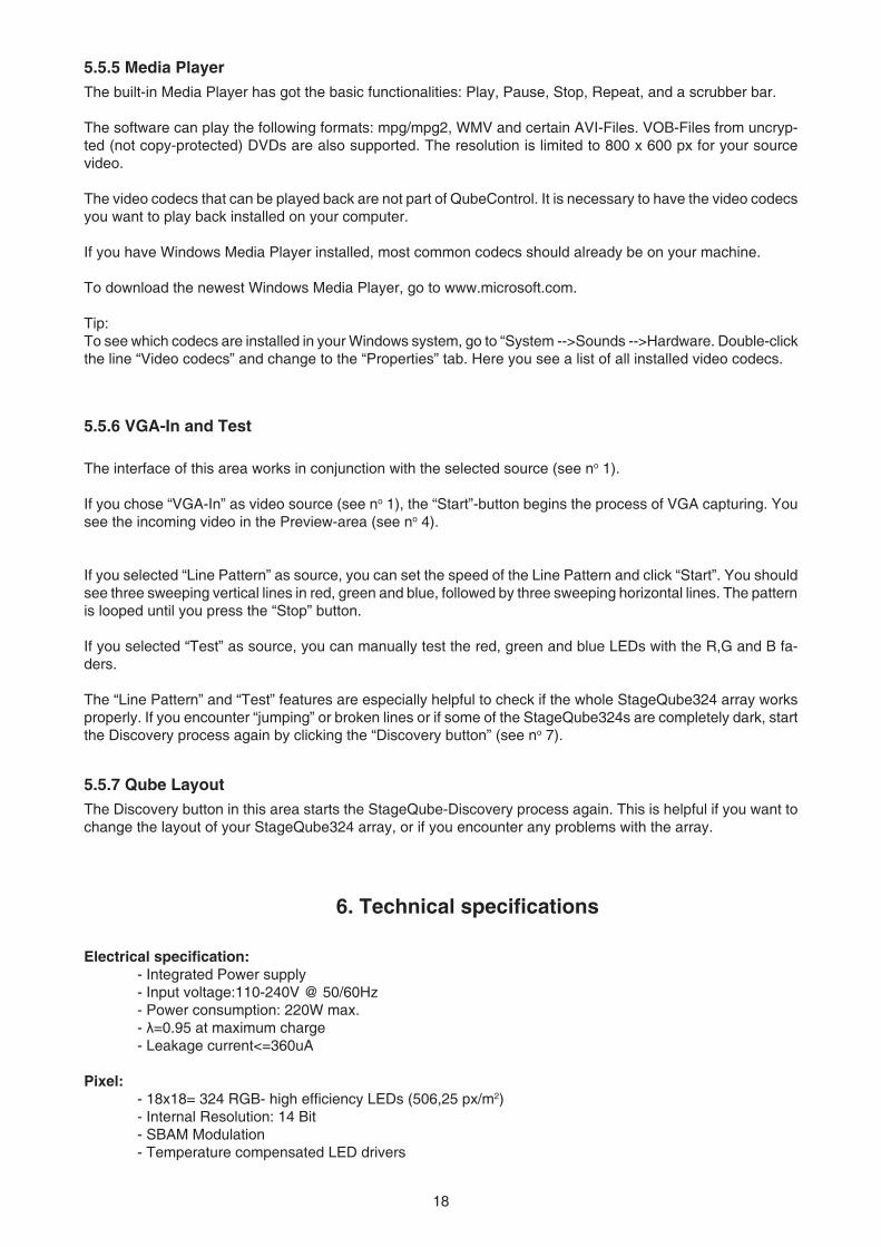
5.5.4 PreviewThe preview area shows the actual output that is distributed to the StageQube324s. You can separately scale the video in x- and y- direction. A red box shows which part of the source video is distributed to the StageQubes. On the right side of the Preview area, 4 buttons give control over the positioning of the output window. See next picture.
18 19
5.5.5 Media PlayerThe built-in Media Player has got the basic functionalities: Play, Pause, Stop, Repeat, and a scrubber bar. The software can play the following formats: mpg/mpg2, WMV and certain AVI-Files. VOB-Files from uncryp-ted (not copy-protected) DVDs are also supported. The resolution is limited to 800 x 600 px for your source video.
The video codecs that can be played back are not part of QubeControl. It is necessary to have the video codecs you want to play back installed on your computer.
If you have Windows Media Player installed, most common codecs should already be on your machine.
To download the newest Windows Media Player, go to www.microsoft.com.
Tip:To see which codecs are installed in your Windows system, go to “System -->Sounds -->Hardware. Double-click the line “Video codecs” and change to the “Properties” tab. Here you see a list of all installed video codecs.
5.5.6 VGA-In and Test
The interface of this area works in conjunction with the selected source (see no 1).
If you chose “VGA-In” as video source (see no 1), the “Start”-button begins the process of VGA capturing. You see the incoming video in the Preview-area (see no 4).
If you selected “Line Pattern” as source, you can set the speed of the Line Pattern and click “Start”. You should see three sweeping vertical lines in red, green and blue, followed by three sweeping horizontal lines. The pattern is looped until you press the “Stop” button.
If you selected “Test” as source, you can manually test the red, green and blue LEDs with the R,G and B fa-ders.
The “Line Pattern” and “Test” features are especially helpful to check if the whole StageQube324 array works properly. If you encounter “jumping” or broken lines or if some of the StageQube324s are completely dark, start the Discovery process again by clicking the “Discovery button” (see no 7).
5.5.7 Qube LayoutThe Discovery button in this area starts the StageQube-Discovery process again. This is helpful if you want to change the layout of your StageQube324 array, or if you encounter any problems with the array.
6. Technical specifications
Electrical specification: - Integrated Power supply - Input voltage:110-240V @ 50/60Hz - Power consumption: 220W max. - λ=0.95 at maximum charge - Leakage current<=360uA
Pixel: - 18x18= 324 RGB- high efficiency LEDs (506,25 px/m2) - Internal Resolution: 14 Bit - SBAM Modulation - Temperature compensated LED drivers
18 19
Mechanical specification: - Dimensions:800x800x120 mm (with diffusor:800x800x180 mm) - Robust metal framing - Integrated mechanical connection system - Connector panel secured with access cover - Adaptors for rigging systems - Inflammability: B1
Optical specification: - Clear covering (PETG with a transmission rate of 90%) - Snap-on diffuser (PETG with a transmission rate of 80 %) - Beam angle without diffusor: approx.120°,with diffusor: approx.170°
Controlling: - Input source:VGA at max. 60 frames/s - One control Unit (QubeControl) grabs the input signal and distributes to all panels in the system - Preview window in the QubeControl software - Very low latency (input-output:max.50ms) Realtime parameters (via QubeControl): - Brightness 1-100% (255 steps.Exponential curve) - Intensity red 1-100% (255 steps.Exponential curve) - Intensity green1-100% (255 steps.Exponential curve) - Intensity blue 1-100% (255 steps.Exponential curve) - Gamma 1.0-3.0 in steps of 0.1 - Release time 0 - 1.000 ms in steps of 4 ms - LED frame rate 600-1,100 frames/s in steps of 2 frames/s
- Scalling factor of the grabbed videostream - Frame size and position - Size and form of the StageQube 324 array
Startup procedure,wiring and controlling: - Intuitive,graphical and fast startup without any manual addressing - Definition of non-rectangular arrays - Distribution of video data over 1000Base -T- Ethernet (CAT 5e,6 or 7 cable) - Automatic brightness detection and optimization for maximum brightness of the array, important for dry-hire use - Daisy chain of power cable for up to 8 StageQubes 324 with Neutrick EtherCon connectors - Integrated Ethernet switch with 3 Ethernet ports (Neutrick Ethercon) - Daisy chain of up to 8 StageQube324´s Ethernet connection,the third Ethernet connector allows (theoretically) 255 StageQube 324 in a system without any additional hardware (tree structure)