Embed Size (px)
Citation preview

SÜS
Vibration Monitoring System

VibrationMonitoring System
Vibration Behavior provides Information of Mechanical Conditions.
The SÜS vibration monitoring system detects changes in the vibration behavior of primary circuit components, reactor pressure vessel internals and reactor coolant pumps in pressurized water reactors at an early stage by frequency and amplitude monitoring of the mechanical component vibrations. It meets the specifications and requirements laid down in KTA 3201.4, KTA 3204, DIN 25475/2, VDI 2059, ISO 7919, ISO 10816 and IEC 61502.
A change in the vibration behavior of a component is one of the most sensitive indicators for changes in its mechanical condition, e.g.
• relaxation of tensioning of the flow skirt fixing bolts,
• relaxation of the stiffness of core barrel hold-down springs,
• damage to the journal bearing of a reactor coolant pump,
• contact between primary circuit components and building,
• incipient crack in the shaft of a reactor coolant pump.
Vibration behavior is monitored automatically to a great extendduring normal steady-state operation. The measured signals are electrically amplified, digitized and synchronously transformed to the frequency domain in a multi-channel signal processor.
The current resulting characteristic vibration functions and variables are compared with those of the reference status and are graphically represented in the form of a trend chart. If the deviations violate predefined attention thresholds, SÜS announces this in the control room and indicates the affected characteristic vibration variable and the affected component via a 3-D figure of the monitored object on the SÜS screen. The attention thresholds are based on empirical values, structure dynamics calculations and experimental analyses.
The characteristic vibration behavior of each component depends on its mechanical properties and can be described in terms of characteristic variables. These characteristic variables (e.g. frequency, magnitude) are determined using characteristic vibration functions (preferably auto power spectral densities). In the case of coupled components, each characteristic function contains the characteristic variables of several components. When the vibration behavior of one component changes, the values of its dedicated characteristic variables change.
The assignment of characteristic variables to components is based on experiments and/or calculations as well as on commissioning measurements with additionally temporary installed vibration sensors.
Settings for the performance of vibration monitoring by the SÜS are defined in the form of configuration templates.
• Monitored objects (object designation e.g. RCS or RCPs, monitored components, vibration types, signals and acquired operational parameters)
• Measurement templates (measurement in time-/frequency domain, channel settings, measurement with/without calibration…)
• Monitoring (characteristic functions, monitoring parameters, reference values, attention thresholds, monitoring cycles, alarm criteria)
2

Monitoring results can be presented
via a 3-D-figure of the monitored object
The monitoring results are presented via a 3-D-figure of the monitored object. SÜS makes available the analyses functions of high-performance FFT analyzers to determine
• signals in time domain,• orbits,• RMS- and peak values,• auto-power spectra,• coherence functions,• transfer functions.
Analyses functions and monitoring results are illustrated e.g. in
• single diagrams,• multiple diagrams,• frequency trend charts,• magnitude trend charts,• quotient spectra.
3
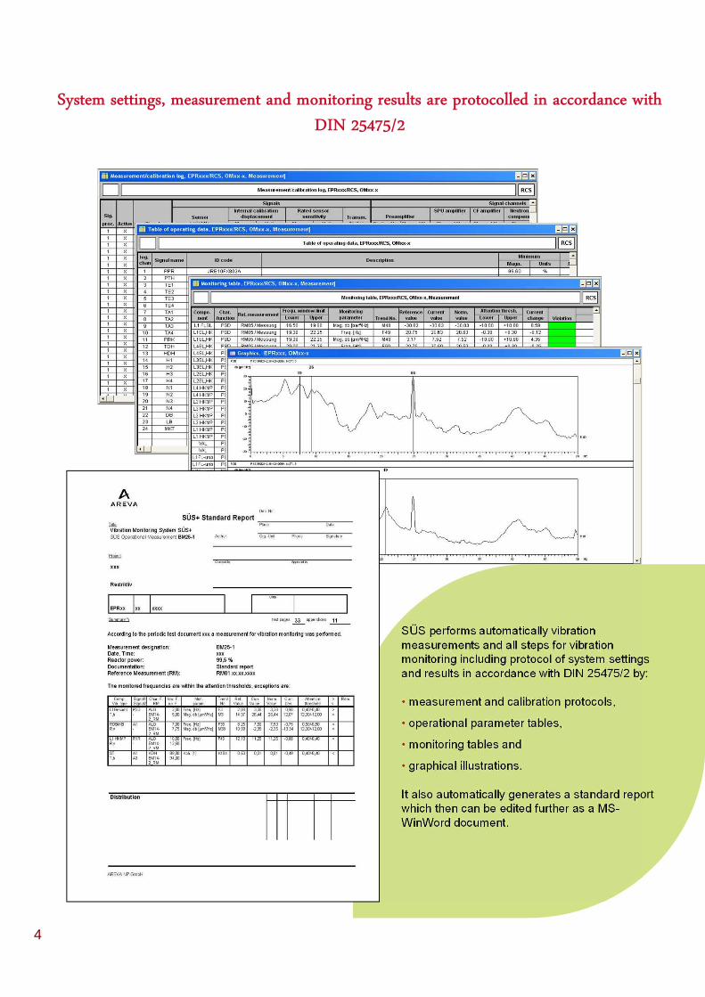
SÜS performs automatically vibration measurements and all steps for vibration monitoring including protocol of system settings and results in accordance with DIN 25475/2 by:
• measurement and calibration protocols,
• operational parameter tables,
• monitoring tables and
• graphical illustrations.
It also automatically generates a standard report which then can be edited further as a MS-WinWord document.
System settings, measurement and monitoring results are protocolled in accordance with
DIN 25475/2
4

Complete Vibration Monitoring of Reactor Pressure Vessel Internals,
Reactor Coolant System and Reactor Coolant Pumps
Vibration Monitoring of Structures and Rotating Machines
The AREVA NP GmbH vibration monitoring system, SÜS is a complete solution for vibration monitoring of the reactor pressure vessel internals, reactor coolant system and reactor coolant pumps.
SÜS monitors the mechanical vibrations of passive structures in the frequency domain and rotating machines in the frequency domain for early warning and in the time domain for machinery protection purposes.
AREVA NP GmbH – as a manufacturer of nuclear power plant components – already has more than 30 years of experience with vibration monitoring systems applied in AREVA NP GmbH and non-AREVA NP GmbH plants. By using SÜS the plant operators can take advantage of the wealth of this experience which has been integrated in the evaluation procedures of the SÜS system.
SÜS vibration monitoring systems are currently being used to monitor safety-related components in 33 PWRs.
A Complete Solution from the Sensor up to the Analysis and Monitoring System
The systematic SÜS concept starts with the selection of sensors which were specially developed for the measurement of vibrations in power plant components – e.g. the SAUM absolute displacement transducer – and optimized for their application in terms of sensitivity and frequency range. They are qualified for use in the harsh conditions prevailing in nuclear power plants and can be remotely calibrated at any time.
SÜS automatically performs a calibration of all instrument chains prior to each measurement and documents the current settings. This is the only possible way to implement a really automatic vibration monitoring procedure which excludes incorrect measurements and poorly adjusted instrument chains.
The modular design of SÜS guarantees service-friendliness as well as simple extensions to the system and its software.
5

A Complete Solution from the Function Test up to the Results Report
SÜS performs all the routine tasks required for the vibration monitoring:
• start of measurement at the required time (single or cyclical operation)
• selection, calibration and adjustment of required instrument chains
• data acquisition
• calculation of the characteristic vibration variables, detection of changes and indication of the threshold violations
• display of monitoring results in a 3-D figure
• recording of process parameters
• documentation of results in report and graphical form.
In the case of threshold violations the system provides information of the affected components.
A Complete Solution from the Design up to the Service
The SÜS vibration monitoring system is further enhanced by a comprehensive range of vibration monitoring services:
• concept and configuration of vibration monitoring
• development and production of systems: new system/conversion/upgrades
• installation and commissioning
• system service and maintenance
• performance and evaluation of vibration measurements (reference measurements, Cyclic recurrent measurements, special measurements)
• archiving of data, trend analysis and documentation suitable for independent experts
• dynamic tests in the vibration laboratory and at the plant
• instruction, practical training and advice
6

Technical Data
Sensorsfor
Absolutedisplacement
Relativedisplacement
Pressure fluctuation
AccelerationRelative
shaft displacement
Absolute velocity
Neutron flux noise(from operational instrumentation)
Measurement principle
inductive inductive piezo-electric eddy current electro-dynamic
electrical current by ionized gas
Amplifier carrier frequency amplifier charge amplifier - -compensation
amplifier
GeneralCodes and standards: SÜS fulfills the requirements and recommendations stipulated in KTA 3204,
KTA 3201.4, DIN 25475/2, VDI 2059, ISO 7919, ISO 10816 und IEC 61502 Operating mode: automatic monitoring measurements (single measurement on request, cyclic or
continously measurements)User interface: MS-Windows
Signal processor: max. 2x 96-channel signal processors (96 channels simultaneously, 48 channels simultaneously correlated, sampling rate ≥ 1024 Hz, frequency range 0-50/0-200Hz)
Computer: Industrial-PC with Pentium® -Processor, operating system Windows 2000/XP
Automatized system functions:
• measurement chain control (calibration, balance, compensation)• signal acquisition (filtering, digitizing, Fast Fourier Transformation)• process data acquisition• signal evaluation (calculation of signal characteristic functions and signal
characteristic variables = monitoring parameters)• monitoring (comparison of current parameters with reference parameters and
indication of threshold violations)• evaluation (graphical illustration of characteristic functions and variables)• data management and storage in a data base• dokumentation (standard report in MS-WinWord format)
Signal characteristic functions / variables:
signals in time domain, maximum shaft deflections smax, shaft orbits, RMS values, peak values, auto power spectra, RMS spectra, coherence functions, transfer functions (magnitude and phase), cross power spectra (magnitude and phase), Quotient spectra (for global magnitude monitoring)
Monitored parameters: maximum shaft deflection smax, RMS value, peak value, frequency, magnitude, coherence
Evaluation diagrams: single diagrams, multiple diagrams (superimposed, sequenced, cascade), Trend diagrams
Other features: Protection against maloperation by way of priority-controlled access to system functions, online operating help, check of user inputs for plausibility and validity, offline version available
Software
Frontend/Hardware
Interfaces
• Interface to read process data from the process control system (analog or digital),• Interface to provide the process control system with SÜS measurement values (analog),• Alarm interface to main control room (fault, warning, alarm),• Automatic dispatch of system messages via E-mail,• Automatic data storage on external data carriers or network drives,• Export/Import of data for archieving or data exchange with SÜS offline systems and data bases,• Remote data transfer via ISDN modem (for remote diagnoses and services).
7

Address: AREVA NP GmbH, Paul-Gossen-Str. 100, D-91052 Erlangen, Germany Tel. +49 9131 900 91143 – Email: [email protected]
Cop
yrig
ht ©
200
9 by
AR
EV
A N
P G
mbH
. All
right
s re
serv
ed.
www.areva.com
Copyright © AREVA NP GmbH (2009)
The statements and information contained in this brochure are for advertising purpose only and shall under no circumstances be considered an offer to contract. Nor shall the statements be construed as providing any warranties or performance guarantees, either expressed or implied, including without limitation warranties of merchantability and fitness for a particular purpose.
All over the world, AREVA providesits customers with solutions for carbon-freepower generation and electricity transmission.With its knowledge and expertise in these fields, thegroup has a leading role to play in meeting the world’senergy needs.
Ranked first in the global nuclear power industry, AREVA’sunique integrated offering covers every stage of the fuel cycle,reactor design and construction, and related services.In addition, the group is developing a portfolio of operations inrenewable energies. AREVA is also a world leader in electricitytransmission and distribution and offers its customers acomplete range of solutions for greater grid stability and energyefficiency.
Sustainable development is a core component of the group’sindustrial strategy. Its 75,000 employees work every day tomake AREVA a responsible industrial player that is helpingto supply ever cleaner, safer and more economicalenergy to the greatest number of people.