Embed Size (px)
Citation preview

SKIT Teaching Process Rev No.: 1.0Doc Code: SKIT.Ph5b1.F02 Date: 01-01-2020
Title: Course Plan Page: 1 / 49
Copyright ©2017. cAAS. All rights reserved. COURSE PLAN – CAY 2019-20 BE-5-ME-SKIT-Ph5b1-F02-V2.2
SRI KRISHNA INSTITUTE OF TECHNOLOGY, BENGALURU
COURSE PLAN
Academic Year 2019 – 20
Program: B E
Semester : 6/A
Course Code: 17MEL67
Course Title: Heat Transfer Lab
Credit / L-T-P: 2/ 1-0-2
Total Contact Hours: 30
Course Plan Author: APPESE S D
#29, Hesaraghatta Main road, Chimney Hills, Chikkabanavara P.O., Bengaluru – 560090, Karnataka, INDIA
Phone / Fax :+91 80 23721477 -STD- 080-23721477Web: http://www.skit.org.in/ ,
e-mail: [email protected] / [email protected]
ME-17MEL67 Page # 1 / 49 Copyright ©2017. cAAS. All rights
Prepared by Checked by Approved by
File No:

SKIT Teaching Process Rev No.: 1.0Doc Code: SKIT.Ph5b1.F02 Date: 01-01-2020
Title: Course Plan Page: 2 / 49
Copyright ©2017. cAAS. All rights reserved. COURSE PLAN – CAY 2019-20 BE-5-ME-SKIT-Ph5b1-F02-V2.2
Table of Contents
17MEL67: Heat Transfer Lab...........................................................................3A. LABORATORY INFORMATION................................................................................................3
1. Lab Overview........................................................................................................................................... 32. Lab Content............................................................................................................................................. 33. Lab Material............................................................................................................................................. 34. Lab Prerequisites: Performance Test on a Vapour Compression Refrigeration.......................................45. General Instructions................................................................................................................................. 46. Lab Specific Instructions.......................................................................................................................... 4
B. OBE PARAMETERS.................................................................................................................51. Lab / Course Outcomes........................................................................................................................... 52. Lab Applications...................................................................................................................................... 5Buildings, Mechanical systems, Refrigeration, Spacecraft, Automotive.......................................................5Buildings, Mechanical systems, Refrigeration, Spacecraft, Automotive.......................................................53. Articulation Matrix.................................................................................................................................... 64. Mapping Justification............................................................................................................................... 6
C. COURSE ASSESSMENT..........................................................................................................71. Course Coverage..................................................................................................................................... 72. Continuous Internal Assessment (CIA)....................................................................................................8
D. EXPERIMENTS.........................................................................................................................8Experiment 01: Determination of Thermal Conductivity of a Metal Rod.......................................................8Experiment 02 : Determination of Overall Heat Transfer Coefficient of a Composite wall.........................10Experiment 03: Determination of Effectiveness of a Metallic fin................................................................12Buildings, Mechanical systems, Refrigeration, Spacecraft, Automotive.....................................................16Experiment 04 :Determination of Heat Transfer Coefficient in a free Convection......................................16Experiment 05 :Determination of Heat Transfer Coefficient in a Forced Convention Flow through a Pipe 19Experiment 06 : Determination of Emissivity of a Surface.........................................................................22Experiment 07 : Analysis of steady and transient heat conduction, temperature distribution of plane walland cylinder using Numerical approach (ANSYS/CFD package)...............................................................25Analysis of steady and transient heat conduction, temperature distribution of plane wall and cylinder usingNumerical approach (ANSYS/CFD package)............................................................................................25Experiment 08 : Determination of Steffan Boltzmann Constant.................................................................27Experiment 09 :Determination of LMDT and Effectiveness in a Parallel Flow and Counter Flow Heat Ex-changers.................................................................................................................................................... 29Experiment 10: Experiments on Boiling of Liquid and Condensation of Vapour........................................34Experiment 11 :Performance Test on a Vapour Compression Refrigeration.............................................38Experiment 12 : Air Conditioning Test Rig.................................................................................................40Experiment 13: Experiment on Transient Conduction Heat Transfer.........................................................43Experiment 14 : Determination of temperature distribution along a rectangular and circular fin subjected toheat loss through convection using Numerical approach (ANSYS/CFD package)....................................46Buildings, Mechanical systems, Refrigeration, Spacecraft, Automotive.....................................................49
ME-17MEL67 Page # 2 / 49 Copyright ©2017. cAAS. All rights
Prepared by Checked by Approved by

SKIT Teaching Process Rev No.: 1.0Doc Code: SKIT.Ph5b1.F02 Date: 01-01-2020
Title: Course Plan Page: 3 / 49
Copyright ©2017. cAAS. All rights reserved. COURSE PLAN – CAY 2019-20 BE-5-ME-SKIT-Ph5b1-F02-V2.2
17MEL67: Heat Transfer Lab
A. LABORATORY INFORMATION1. Lab OverviewDegree: BE Program: MEYear / Semester : 3 / 6 Academic Year: 2019-20Course Title: Heat Transfer Lab Course Code: 17MEL67Credit / L-T-P: 2 / 1-0-2 SEE Duration: 180 MinutesTotal Contact Hours: 30 Hrs SEE Marks: 60CIA Marks: 40 Assignment 1 Course Plan Author: Mr. Appese S D Sign Dt:
Checked By: Mr. Naveen Kumar P Sign Dt :
2. Lab ContentUnit Title of the Experiments Blooms Level
Part-A1 Determination of Thermal Conductivity of a Metal Rod. L3
2 Determination of Overall Heat Transfer Coefficient of a Composite wall L33 Determination of Effectiveness on a Metallic fin. L34 Determination of Heat Transfer Coefficient in a free Convection L35 Determination of Heat Transfer Coefficient in a Forced Convention Flow through a
Pipe.L3
6 Determination of Emissivity of a Surface. L37 Analysis of steady and transient heat conduction, temperature distribution of plane
wall and cylinder using Numerical approach (ANSYS/CFD package).L3
Part-B1 Determination of Steffan Boltzmann Constant.
L3
2 Determination of LMDT and Effectiveness in a Parallel Flow and Counter Flow HeatEx-changers.
L3
3 Experiments on Boiling of Liquid and Condensation of Vapour. L34 Performance Test on a Vapour Compression Refrigeration L35 Performance Test on a Vapour Compression Air – Conditioner L36 Experiment on Transient Conduction Heat Transfer. L37 Determination of temperature distribution along a rectangular and circular fin
subjected to heat loss through convection using Numerical approach (ANSYS/CFDpackage)
L3
3. Lab MaterialUnit Details Available
1 Text booksM. Necati Ozisik, Heat Transfer – A Basic Approach, McGraw Hill, NewYork,2005.
In Lib
2 Incropera, F. P. and De Witt, D. P., Fundamentals of Heat and Mass Transfer, 5 th
Edition, John Wiley and Sons, New York, 2006.In Lib
3 Holman, J. P., Heat Transfer, 9th Edition, Tata McGraw Hill, New York, 2008. In Lib/Dept Lib
ME-17MEL67 Page # 3 / 49 Copyright ©2017. cAAS. All rights
Prepared by Checked by Approved by

SKIT Teaching Process Rev No.: 1.0Doc Code: SKIT.Ph5b1.F02 Date: 01-01-2020
Title: Course Plan Page: 4 / 49
Copyright ©2017. cAAS. All rights reserved. COURSE PLAN – CAY 2019-20 BE-5-ME-SKIT-Ph5b1-F02-V2.2
4. Lab Prerequisites: Performance Test on a Vapour Compression Refrigeration
SNo CourseCode
Course Name Topic / Description Sem Remarks
1 17ME33 Basicthermodynamics
Fundamentals, Work and Heat Interactions 3 -
2 15MEL57 Fluid mechanics Fluid properties, Fluid flows, variation influid flows, turbulent and laminar flow.
4 -
5. General InstructionsS No Forced convection systems applicable for extremely high temperatures for functions
InstructionsRemarks
1 Observation book and Lab record are compulsory.2 Students should report to the concerned lab as per the time table.3 After completion of the program, certification of the concerned staff in-charge in the
observation book is necessary.4 Student should bring a notebook of 100 pages and should enter the readings /observations
into the notebook while performing the experiment.5 The record of observations along with the detailed experimental procedure of the experiment
in the Immediate last session should be submitted and certified staff member in-charge.6 Should attempt all problems / assignments given in the list session wise.7 It is responsibility to create a separate directory to store all the programs, so that nobody
else can read or copy.8 When the experiment is completed, should disconnect the setup made by them, and should
return all the components/instruments taken for the purpose.9 Any damage of the equipment or burn-out components will be viewed seriously either by
putting penalty or by dismissing the total group of students from the lab for thesemester/year
10 Completed lab assignments should be submitted in the form of a Lab Record in which youhave to write the algorithm, program code along with comments and output for various inputsgiven
6. Lab Specific InstructionsS No Specific Instructions Remarks
1 Students must attend the lab classes with ID cards and in the prescribed uniform.2 Students must check if the components, instruments and machinery are in working
condition before setting up the experiment.3 Power supply to the experimental set up/ equipment/ machine must be switched on only
after the faculty checks and gives approval fording the experiment. Students must start tothe experiment. Students must start doing the experiments only after getting permissionsfrom the faculty.
4 Students may contact the lab in charge immediately for any unexpected incident sandemergency
5 The apparatus used for the experiments must be cleaned and returned to the technicians,safely without any damage
6 Make sure, while leaving the lab after the stipulated time, that all the power connectionsare switched off
ME-17MEL67 Page # 4 / 49 Copyright ©2017. cAAS. All rights
Prepared by Checked by Approved by

SKIT Teaching Process Rev No.: 1.0Doc Code: SKIT.Ph5b1.F02 Date: 01-01-2020
Title: Course Plan Page: 5 / 49
Copyright ©2017. cAAS. All rights reserved. COURSE PLAN – CAY 2019-20 BE-5-ME-SKIT-Ph5b1-F02-V2.2
B. OBE PARAMETERS1. Lab / Course Outcomes S no CO s Teach.
HoursInstr Method Assessment
MethodBlooms’
LevelCO1Perform experiments to determine the thermal
conductivity of a metal rod6 Demonstration,
Video, chalk andBoard
Practicalrecord and IA
test
L3
CO2Conduct experiments to determine convective heat transfer coefficient for free and forced convection and correlate with theoretical values.
6 Demonstration, Video, chalk and
Board
Practicalrecord and IA
test
L3
CO3Estimate the effective thermal resistance in composite slabs and efficiency in pin-fin
6 Demonstration, Video, chalk and
Board
Practicalrecord and IA
test
L3
CO4Determine surface Emissivity of a test plate 6 Demonstration, Video, chalk and
Board
Practicalrecord and IA
test
L3
CO5Estimate performance of a refrigerator and effectiveness of fin
6 Demonstration, Video, chalk and
Board
Practicalrecord and IA
test
L3
- Total 30 - - -
2. Lab ApplicationsS No Application Area Level
1 Air conditioning, Fins in all system, Fans, refrigerator, Engine Radiators, cooling heat pipesin electronic Appliances,
L3
2 To compute the heat flux at any location, compute the thermal stress, design of insulationthickness, chip temperature calculation, heat treatment of metals.
L3
3 Buildings, Mechanical systems, Refrigeration, Spacecraft, Automotive L3
4 Metallurgy, heat treating process applications. L35 2-D study state heat conduction equation is applied in CFD analysis( Finite difference and
finite element method)L3
6 Solar flat plate collector, water heating process (solar pond), photo voltaic cell. L37 To compute the heat flux at any location, compute the thermal stress, design of insulation
thickness, chip temperature calculation, heat treatment of metals.L3
8 Forced convection systems applicable for extremely high temperatures for functions L39 Establishing temperature distribution within building, determining heat loss calculations,
ventilating and air-conditioning system.L3
10 Boiling and condensation knowledge is applicable to calculate critical heat flux, andcondensation rate in heat transfer problems.
L3
11 LMTD and NTU methods for analysis of heat ex-changers. L312 Buildings, Mechanical systems, Refrigeration, Spacecraft, Automotive L3
ME-17MEL67 Page # 5 / 49 Copyright ©2017. cAAS. All rights
Prepared by Checked by Approved by
SKIT Teaching Process Rev No.: 1.0Doc Code: SKIT.Ph5b1.F02 Date: 01-01-2020
Title: Course Plan Page: 6 / 49
Copyright ©2017. cAAS. All rights reserved. COURSE PLAN – CAY 2019-20 BE-5-ME-SKIT-Ph5b1-F02-V2.2
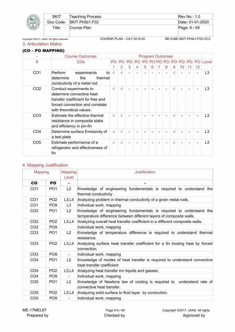
3. Articulation Matrix(CO – PO MAPPING)
- Course Outcomes Program Outcomes# COs PO
1PO2
PO3
PO4
PO5
PO6
PO7
PO8
PO9
PO10
PO11
PO12
Level
CO1 Perform experiments todetermine the thermalconductivity of a metal rod
√ √ - - - - - - √ - - - L3
CO2 Conduct experiments to determine convective heat transfer coefficient for free and forced convection and correlate with theoretical values.
√ √ - - - - - - √ - - - L3
CO3 Estimate the effective thermal resistance in composite slabs and efficiency in pin-fin
√ √ - - - - - - √ - - - L3
CO4 Determine surface Emissivity of a test plate
√ √ - - - - - - √ - - - L3
CO5 Estimate performance of a refrigerator and effectiveness of fin
√ √ - - - - - - √ - - - L3
4. Mapping JustificationMapping Mapping
LevelJustification
CO PO - -CO1 PO1 L2 Knowledge of engineering fundamentals is required to understand the
thermal conductivity .CO1 PO2 L3,L4 Analyzing problem in thermal conductivity of a given metal rods.CO1 PO9 L3 Individual work, mappingCO2 PO1 L2 Knowledge of engineering fundamentals is required to understand the
temperature difference between different layers of composite walls.CO2 PO2 L3,L4 Analyzing overall heat transfer coefficient in a different composite walls.CO2 PO9 Individual work, mappingCO3 PO1 L2 Knowledge of temperature difference is required to understand thermal
resistance.CO3 PO2 L3,L4 Analyzing surface heat transfer coefficient for a fin loosing heat by forced
convection.CO3 PO9 - Individual work, mappingCO4 PO1 L2 Knowledge of modes of heat transfer is required to understand convective
heat transfer coefficientCO4 PO2 L3,L4 Analyzing heat transfer inn liquids and gasses.CO4 PO9 - Individual work, mappingCO5 PO1 L2 Knowledge of Newtons law of cooling is required to understand rate of
convective heat transfer.CO5 PO2 L3,L4 Analyzing solid surface to fluid layer by conduction.CO5 PO9 - Individual work, mapping
ME-17MEL67 Page # 6 / 49 Copyright ©2017. cAAS. All rights
Prepared by Checked by Approved by

SKIT Teaching Process Rev No.: 1.0Doc Code: SKIT.Ph5b1.F02 Date: 01-01-2020
Title: Course Plan Page: 7 / 49
Copyright ©2017. cAAS. All rights reserved. COURSE PLAN – CAY 2019-20 BE-5-ME-SKIT-Ph5b1-F02-V2.2
C. COURSE ASSESSMENT1. Course CoverageUnit Title Teachi
ngHours
No. of question in Exam LevelsCIA-1 CIA-2 CIA-3 Asg-1 Asg-2 Asg-3 SEE
PART-A1 Determination of Thermal
Conductivity of a Metal Rod.03 1 - - - - - 1 L3
2 Determination of Overall HeatTransfer Coefficient of a Compositewall
03 1 - - - - - 1 L3
3 Determination of Effectiveness on aMetallic fin.
03 1 - - - - - 1 L3
4 Determination of Heat TransferCoefficient in a free Convection
03 1 - - - - - 1 L3
5 Determination of Heat TransferCoefficient in a Forced ConventionFlow through a Pipe.
03 1 - - - - - 1 L3
6 Determination of Emissivity of aSurface.
03 1 - - - - - 1 L3
7 Analysis of steady and transientheat conduction, temperaturedistribution of plane wall andcylinder using Numerical approach(ANSYS/CFD package).
03 - - - - - - 1 L3
PART-B1 Determination of Steffan Boltzmann
Constant.
03 1 - - - - - 1 L3
2 Determination of LMDT andEffectiveness in a Parallel Flow andCounter Flow Heat Ex-changers.
03 1 - - - - - 1 L3
3 Experiments on Boiling of Liquidand Condensation of Vapour.
03 1 - - - - - 1 L3
4 Performance Test on a VapourCompression Refrigeration
03 1 - - - - - 1 L3
5 Performance Test on a VapourCompression Air – Conditioner
03 1 - - - - - 1 L3
6 Experiment on TransientConduction Heat Transfer.
03 1 - - - - - 1 L3
7 Determination of temperaturedistribution along a rectangular andcircular fin subjected to heat lossthrough convection using Numericalapproach (ANSYS/CFD package)
03 1 - - - - - 1 L3
- Total 42 -
ME-17MEL67 Page # 7 / 49 Copyright ©2017. cAAS. All rights
Prepared by Checked by Approved by
SKIT Teaching Process Rev No.: 1.0Doc Code: SKIT.Ph5b1.F02 Date: 01-01-2020
Title: Course Plan Page: 8 / 49
Copyright ©2017. cAAS. All rights reserved. COURSE PLAN – CAY 2019-20 BE-5-ME-SKIT-Ph5b1-F02-V2.2
2. Continuous Internal Assessment (CIA)Evaluation Weight age in Marks CO Levels
CIA Exam – 1 30 CO1, CO2, CO3,CO4,CO5
L3
Assignment – 1 5 CO1, CO2, CO3,CO4,CO5
L3
Other Activities – define –Slip test
5 CO1 to CO5 L3
Final CIA Marks 40 - -
D. EXPERIMENTSExperiment 01: Determination of Thermal Conductivity of a Metal Rod.
- Experiment No.: 1 Marks DatePlanned
DateConducted
1 Title Determination of Thermal Conductivity of a Metal Rod
2 Course Outcomes Perform experiments to determine the thermal conductivity of a metal rod
3 Aim To determine the thermal conductivity of the given metal rod
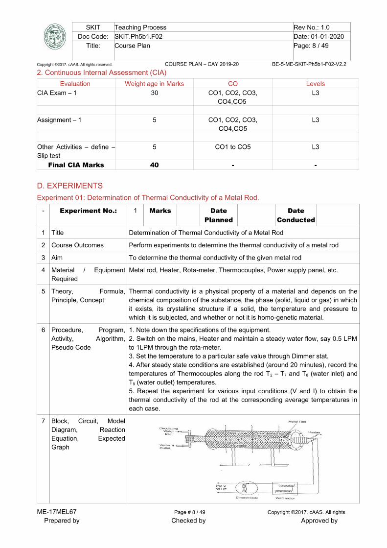
4 Material / EquipmentRequired
Metal rod, Heater, Rota-meter, Thermocouples, Power supply panel, etc.
5 Theory, Formula,Principle, Concept
Thermal conductivity is a physical property of a material and depends on thechemical composition of the substance, the phase (solid, liquid or gas) in whichit exists, its crystalline structure if a solid, the temperature and pressure towhich it is subjected, and whether or not it is homo-genetic material.
6 Procedure, Program,Activity, Algorithm,Pseudo Code
1. Note down the specifications of the equipment.2. Switch on the mains, Heater and maintain a steady water flow, say 0.5 LPMto 1LPM through the rota-meter.3. Set the temperature to a particular safe value through Dimmer stat.4. After steady state conditions are established (around 20 minutes), record thetemperatures of Thermocouples along the rod T2 – T7 and T8 (water inlet) andT9 (water outlet) temperatures. 5. Repeat the experiment for various input conditions (V and I) to obtain thethermal conductivity of the rod at the corresponding average temperatures ineach case.
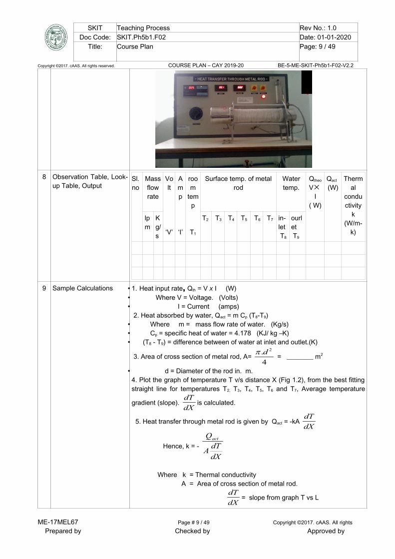
7 Block, Circuit, ModelDiagram, ReactionEquation, ExpectedGraph
ME-17MEL67 Page # 8 / 49 Copyright ©2017. cAAS. All rights
Prepared by Checked by Approved by
SKIT Teaching Process Rev No.: 1.0Doc Code: SKIT.Ph5b1.F02 Date: 01-01-2020
Title: Course Plan Page: 9 / 49
Copyright ©2017. cAAS. All rights reserved. COURSE PLAN – CAY 2019-20 BE-5-ME-SKIT-Ph5b1-F02-V2.2
8 Observation Table, Look-up Table, Output
Sl. no
Massflowrate
Volt
‘V’
Amp
‘I’
room
temp
T1
Surface temp. of metalrod
Watertemp.
Qtheo
VI
( W)
Qact
(W)Therm
alconductivity
k(W/m-
k)
lpm
Kg/s
T2 T3 T4 T5 T6 T7 in-let T8
ourlet T9
9 Sample Calculations • 1. Heat input rate, Qth = V x I (W) • Where V = Voltage. (Volts)• I = Current (amps)
2. Heat absorbed by water, Qact = m Cp (T8-T9)• Where m = mass flow rate of water. (Kg/s)• Cp = specific heat of water = 4.178 (KJ/ kg –K)• (T8 - T9) = difference between of water at inlet and outlet.(K)
3. Area of cross section of metal rod, A= 4
. 2d = ________ m2
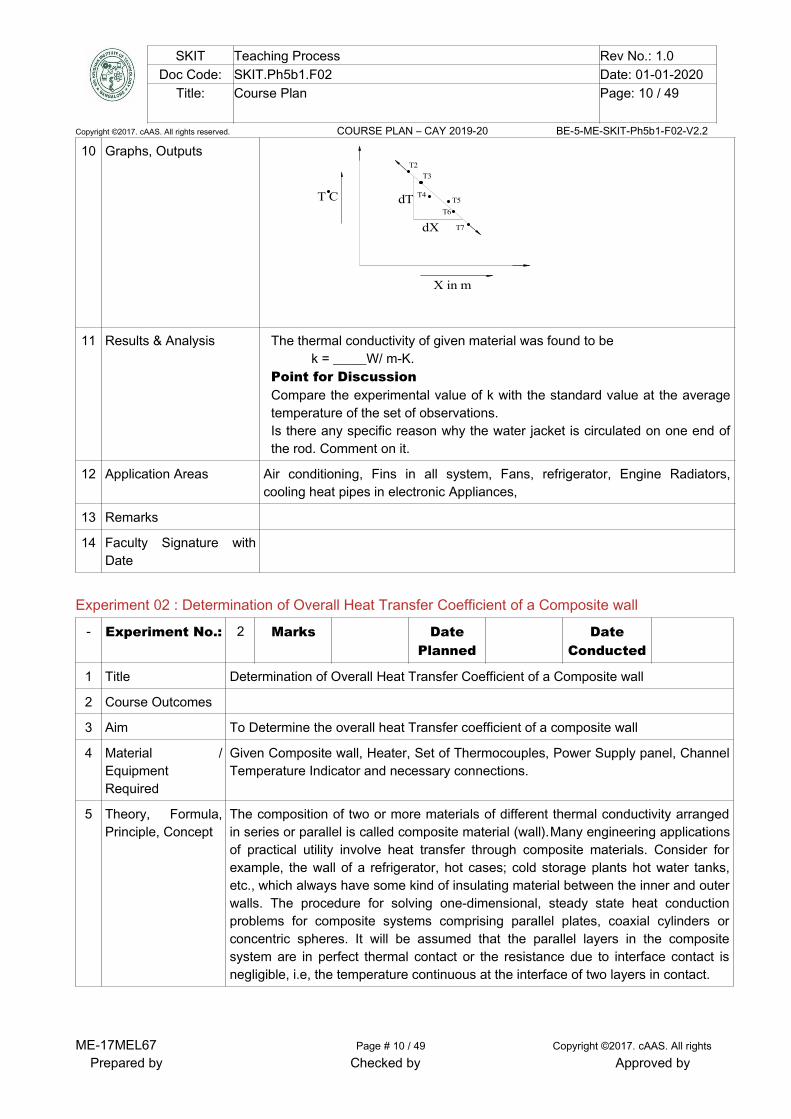
• d = Diameter of the rod in. m.4. Plot the graph of temperature T v/s distance X (Fig 1.2), from the best fittingstraight line for temperatures T2, T3, T4, T5, T6 and T7, Average temperature
gradient (slope). dX
dTis calculated.
5. Heat transfer through metal rod is given by Qact = -kA dX
dT
Hence, k = - dX
dTA
Qact
Where k = Thermal conductivity A = Area of cross section of metal rod.
dX
dT= slope from graph T vs L
ME-17MEL67 Page # 9 / 49 Copyright ©2017. cAAS. All rights
Prepared by Checked by Approved by
SKIT Teaching Process Rev No.: 1.0Doc Code: SKIT.Ph5b1.F02 Date: 01-01-2020
Title: Course Plan Page: 10 / 49
Copyright ©2017. cAAS. All rights reserved. COURSE PLAN – CAY 2019-20 BE-5-ME-SKIT-Ph5b1-F02-V2.2
10 Graphs, Outputs
dT
dX
T C
X in m
T2
T3
T4T5
T6
T7
11 Results & Analysis The thermal conductivity of given material was found to be k = _____W/ m-K.
Point for DiscussionCompare the experimental value of k with the standard value at the averagetemperature of the set of observations.Is there any specific reason why the water jacket is circulated on one end ofthe rod. Comment on it.
12 Application Areas Air conditioning, Fins in all system, Fans, refrigerator, Engine Radiators,cooling heat pipes in electronic Appliances,
13 Remarks
14 Faculty Signature withDate
Experiment 02 : Determination of Overall Heat Transfer Coefficient of a Composite wall
- Experiment No.: 2 Marks DatePlanned
DateConducted
1 Title Determination of Overall Heat Transfer Coefficient of a Composite wall
2 Course Outcomes
3 Aim To Determine the overall heat Transfer coefficient of a composite wall
4 Material /EquipmentRequired
Given Composite wall, Heater, Set of Thermocouples, Power Supply panel, ChannelTemperature Indicator and necessary connections.
5 Theory, Formula,Principle, Concept
The composition of two or more materials of different thermal conductivity arrangedin series or parallel is called composite material (wall).Many engineering applicationsof practical utility involve heat transfer through composite materials. Consider forexample, the wall of a refrigerator, hot cases; cold storage plants hot water tanks,etc., which always have some kind of insulating material between the inner and outerwalls. The procedure for solving one-dimensional, steady state heat conductionproblems for composite systems comprising parallel plates, coaxial cylinders orconcentric spheres. It will be assumed that the parallel layers in the compositesystem are in perfect thermal contact or the resistance due to interface contact isnegligible, i.e, the temperature continuous at the interface of two layers in contact.
ME-17MEL67 Page # 10 / 49 Copyright ©2017. cAAS. All rights
Prepared by Checked by Approved by

SKIT Teaching Process Rev No.: 1.0Doc Code: SKIT.Ph5b1.F02 Date: 01-01-2020
Title: Course Plan Page: 11 / 49
Copyright ©2017. cAAS. All rights reserved. COURSE PLAN – CAY 2019-20 BE-5-ME-SKIT-Ph5b1-F02-V2.2
6 Procedure,Program, Activity,Algorithm, PseudoCode
• Switch on the mains and console.• Set the water flow rate to 1-2 lpm (Fixed).• The heat input to the heater is fixed for any desired value.• After steady state is reached, average temperature of the slabs at the inter
faces are noted. • By varying the heat input to the system through variac, different sets of
readings can be obtained. Repeat the above operations for given Heat inputs.
7 Block, Circuit,Model Diagram,Reaction Equation,Expected Graph
Steel plate
Copper slab
wooden slab
stainlesssteel
HeaterT2
T
T
4
8
water inwater out
Watercirculation
T9
T
T
3
5
T6
T7
8 Observation Table,Look-up Table,Output
SlNo
Voltage‘ V ’Volts
Current ‘ I ’ Amps
Temperatures ( 0C ) Water inlettemperature T8(0C )
Water outlettemperature T9(0C )
T1 T2 T3 T4 T5 T6 T7
9 SampleCalculations
(a) Heat flow through composite wall Q = V x I. (W)
Q = 1
3211 )(
L
TTAk =
2
5422 )(
L
TTAk =
3
7633 )(
L
TTAk .............(1)
k1= Thermal conductivity of Mild steel. L1 = thickness of Mild Steel.k2 = Thermal conductivity of Wood. L2 = thickness of wood.k3 = Thermal conductivity of copper. L3 = thickness of copper. From equation..(1)
ME-17MEL67 Page # 11 / 49 Copyright ©2017. cAAS. All rights
Prepared by Checked by Approved by

SKIT Teaching Process Rev No.: 1.0Doc Code: SKIT.Ph5b1.F02 Date: 01-01-2020
Title: Course Plan Page: 12 / 49
Copyright ©2017. cAAS. All rights reserved. COURSE PLAN – CAY 2019-20 BE-5-ME-SKIT-Ph5b1-F02-V2.2
k1 = )( 321
1
TTA
QL
, Where A=
4
. 2dd = Diameter of the slab
k2 = )( 542
2
TTA
QL
, A1 = A2 = A3 = A.
k3 = )( 763
3
TTA
QL
,
(b) Overall heat transfer coefficient (Uo)
1/ Uo = 1
1
k
L+
2
2
k
L+
3
3
k
L , (
Km
W
2 )
10 Graphs, Outputs Result: The Overall heat transfer co-efficient of given composite slab was found tobe U0 = _____W/ m-K.Points for discussion:-
1) Comment on the experimental set up,its validity and accuracy.2) Overall heat transfer co-efficient can also be calculated without the
requirement of intermediate temperatures. comment on it.
11 Results & Analysis
12 Application Areas To compute the heat flux at any location, compute the thermal stress, design ofinsulation thickness, chip temperature calculation, heat treatment of metals.
13 Remarks
14 Faculty Signaturewith Date
Experiment 03: Determination of Effectiveness of a Metallic fin.
- ExperimentNo.:
3 Marks DatePlanned
DateConducted
1 Title Determination of Effectiveness on a Metallic fin.
2 Course Outcomes Estimate the effective thermal resistance and efficiency in pin-fin
3 Aim To determine the efficiency and effectiveness of the fin by natural convection andforced convection using pin fin apparatus.
4 Material /EquipmentRequired
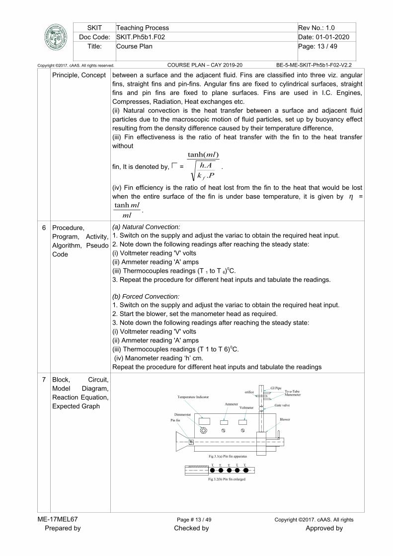
The experimental set up consists of a blower unit having a rectangular duct insidewhich the pin fin is fitted. One end of the pin fin is connected to heater. FiveThermocouples are embedded on the fin surface. Blower along with the orifice isused to measure flow of air through the duct. Input to heater is given through dimmerstat and measured by voltmeter and ammeter. Air flow is controlled by the gate valveand is measured with the help of orifice meter and the manometer fitted on the board.
5 Theory, Formula, (i) Fins are extended surfaces which are used to increase the rate of heat transfer
ME-17MEL67 Page # 12 / 49 Copyright ©2017. cAAS. All rights
Prepared by Checked by Approved by
SKIT Teaching Process Rev No.: 1.0Doc Code: SKIT.Ph5b1.F02 Date: 01-01-2020
Title: Course Plan Page: 13 / 49
Copyright ©2017. cAAS. All rights reserved. COURSE PLAN – CAY 2019-20 BE-5-ME-SKIT-Ph5b1-F02-V2.2
Principle, Concept between a surface and the adjacent fluid. Fins are classified into three viz. angularfins, straight fins and pin-fins. Angular fins are fixed to cylindrical surfaces, straightfins and pin fins are fixed to plane surfaces. Fins are used in I.C. Engines,Compresses, Radiation, Heat exchanges etc. (ii) Natural convection is the heat transfer between a surface and adjacent fluidparticles due to the macroscopic motion of fluid particles, set up by buoyancy effectresulting from the density difference caused by their temperature difference, (iii) Fin effectiveness is the ratio of heat transfer with the fin to the heat transferwithout
fin, It is denoted by, = Pk
Ah
ml
f .
.
)tanh(
.
(iv) Fin efficiency is the ratio of heat lost from the fin to the heat that would be lostwhen the entire surface of the fin is under base temperature, it is given by η =
ml
mltanh.
6 Procedure,Program, Activity,Algorithm, PseudoCode
(a) Natural Convection: 1. Switch on the supply and adjust the variac to obtain the required heat input. 2. Note down the following readings after reaching the steady state: (i) Voltmeter reading 'V' volts(ii) Ammeter reading 'A' amps (iii) Thermocouples readings (T 1 to T 6)0C. 3. Repeat the procedure for different heat inputs and tabulate the readings.
(b) Forced Convection: 1. Switch on the supply and adjust the variac to obtain the required heat input. 2. Start the blower, set the manometer head as required. 3. Note down the following readings after reaching the steady state: (i) Voltmeter reading 'V' volts(ii) Ammeter reading 'A' amps (iii) Thermocouples readings (T 1 to T 6)0C. (iv) Manometer reading ‘h’ cm.Repeat the procedure for different heat inputs and tabulate the readings
7 Block, Circuit,Model Diagram,Reaction Equation,Expected Graph
Pin fin
Gate valve
orificeGI Pipe
To u-TubeManometer
T T T T T1 2 3 4 5
Temperature Indicator
AmmeterVoltmeter
DimmerstatBlower
Fig 3.1(a) Pin fin apparatus
Fig 3.2(b) Pin fin enlarged
ME-17MEL67 Page # 13 / 49 Copyright ©2017. cAAS. All rights
Prepared by Checked by Approved by

SKIT Teaching Process Rev No.: 1.0Doc Code: SKIT.Ph5b1.F02 Date: 01-01-2020
Title: Course Plan Page: 14 / 49
Copyright ©2017. cAAS. All rights reserved. COURSE PLAN – CAY 2019-20 BE-5-ME-SKIT-Ph5b1-F02-V2.2
8 Observation Table,Look-up Table,Output
Sl.
No.
Voltage
( V )
Volts
Current
amps
Power
Q=VI
Watts
Temperature at differentpoint in the outer surface
of cylinder (ºC)
hthe
W/m2-K
the
(%)
exp
(%)
T2 T3 T4 T5 T6
9 SampleCalculations
(1) Experimental Efficiency of pin fin(ηexp)The efficiency of the pin fin experimentally is given by
ηexp = maxfin
fin
Q
Q
Where, Qfin = V x I, W (Qfin)max = hexp.AS.( Ts – Ta) + S.( Ts
4 – Ta4), W
But, hexp = Qfin / {As (Ts – Ta) AS = π.d.l. (m2)(2) Theoretical Efficiency of pin fin(ηthe)
ηthe = ml
mltanh
Where, m = Ak
Ph
f .
.
h = heat transfer coefficient of fin P = Perimeter of fin (D)
kf = thermal conductivity of pin fin = 110 (Km
W
)
A= Area of fin= 4
. 2d (d = Diameter of the pin fin, m), m2
l = Length of pin fin, m To find heat transfer coefficient of fin(h)
1) Film temperature, Tf =2
TaTs ( °C )
ME-17MEL67 Page # 14 / 49 Copyright ©2017. cAAS. All rights
Prepared by Checked by Approved by
SKIT Teaching Process Rev No.: 1.0Doc Code: SKIT.Ph5b1.F02 Date: 01-01-2020
Title: Course Plan Page: 15 / 49
Copyright ©2017. cAAS. All rights reserved. COURSE PLAN – CAY 2019-20 BE-5-ME-SKIT-Ph5b1-F02-V2.2
Where, Ts = Surface temperature of the cylinder =5
65432 TTTTT
(K)
Ta = T1,ambient temperature (K)
Properties of air at the film temperature (Tf) is obtained from data book, hence
determine
Kinematic viscosity, ν = Thermal conductivity, k =
Prandtl number, Pr =
(ii) Grassoff number Gr =2
3...
dg
Where,
β = Co-efficient of thermal expansion = )273(
1
fT. (K-l
)
∆T = Tf -T1. (K)
d = Diameter of the pin fin. (m)
ν = Kinematic viscosity. (m2 /s) Ra. No= Gr x Pr =
From heat transfer Data hand book corresponding to this value of Rayleigh numberRa, the nusselt number(Nu) is given by Forced convection systems applicable for extremely high temperatures for functions
For 10-1 < Gr Pr < 104, Nu = 0.68 +444.05625.0
25.0
Pr
492.01
Pr)(67.0
Gr
For 104 < Gr Pr < 109, Nu = 0.59 (Gr x Pr)0.25
For 109 < Gr Pr < 1012, Nu = 0.13 (Gr x Pr)0.33
Hence,
Nu =k
lh.. Or
h = l
kNu..
Where, h= hthe = natural heat transfer co-efficient, (Km
W
2 )
ME-17MEL67 Page # 15 / 49 Copyright ©2017. cAAS. All rights
Prepared by Checked by Approved by
SKIT Teaching Process Rev No.: 1.0Doc Code: SKIT.Ph5b1.F02 Date: 01-01-2020
Title: Course Plan Page: 16 / 49
Copyright ©2017. cAAS. All rights reserved. COURSE PLAN – CAY 2019-20 BE-5-ME-SKIT-Ph5b1-F02-V2.2
(3) Effectiveness of Fin, Pk
Ah
ml
f .
.
)tanh(
10 Graphs, Outputs
11 Results & Analysis Result:- free convection hthe = ______ , ηexp = _______ , forced convection hthe = ______ , ηexp = _______,
Points for discussion:-(1) If the readings are taken when the steady state is yet to be reached,how will theaccuracy of the results will be affected.(2) From the observations taken in this experiment, explain how would you determinethe thermal conductivity of the material of the fin.
12 Application Areas Buildings, Mechanical systems, Refrigeration, Spacecraft, Automotive
13 Remarks
14 Faculty Signaturewith Date
Experiment 04 :Determination of Heat Transfer Coefficient in a free Convection
- ExperimentNo.:
4 Marks DatePlanned
DateConducte
d
1 Title Determination of Heat Transfer Coefficient in a free Convection
2 Course Outcomes Conduct experiments to determine convective heat transfer coefficient
3 Aim To determine Heat Transfer Coefficient in a free Convection
4 Material /EquipmentRequired
The apparatus consists of a brass tube fitted in a rectangular duct in a verticalposition. The duct is open at the top and bottom and forms an enclosure andserves the purpose of undisturbed surrounding. An electric heating element is keptin the vertical tube which in turn heats the tube surface. The heat is lost from thetube to the surrounding air by natural convection. The temperature of the verticaltube is measured by six Thermocouples. The heat input to the heater is measuredby an Ammeter and a Voltmeter and is varied by a dimmer stat. The tube surfaceis polished to minimize the radiation losses.
5 Theory, Formula,Principle, Concept
natural convection is the mode of heat transfer from hot radiators, refrigeratingcoils etc. It is heat transfer between a surface and adjacent fluid particles due tothe macroscopic motion of fluid particles, set up by buoyancy effect resulting fromthe density difference caused by their temperature difference. The heat transferrate (Q) in free convection is given by Newton’s law of cooling given by
Q = hAs( Ts - T∞ )
Where, As - Surface area. (m2)
ME-17MEL67 Page # 16 / 49 Copyright ©2017. cAAS. All rights
Prepared by Checked by Approved by
SKIT Teaching Process Rev No.: 1.0Doc Code: SKIT.Ph5b1.F02 Date: 01-01-2020
Title: Course Plan Page: 17 / 49
Copyright ©2017. cAAS. All rights reserved. COURSE PLAN – CAY 2019-20 BE-5-ME-SKIT-Ph5b1-F02-V2.2
(Ts - T∞) - Temperature difference between the surface and fluid. (K)
h - Heat transfer co-efficient (usually 5 to 25 (Km
W
2 ) for natural convection for
air)
6 Procedure,Program, Activity,Algorithm, PseudoCode
1. Switch on the electric heater and adjust the auto transformer.
2. Wait for steady state to be reached.
3. Note down the required readings like Voltage, Current and Thermocouplesreadings
T2 – T7 along the rod
4. Calculate heat transfer co-efficient for natural convection.
5. Also determine the heat transfer co-efficient using the empirical relationcompare
the values.
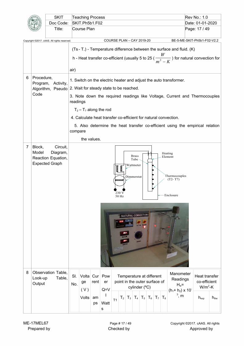
7 Block, Circuit,Model Diagram,Reaction Equation,Expected Graph
Thermocouples (T2- T7)
230 V50 Hz
HeatingElementBrass
Tube
Wattmeter
Dimmerstat
Enclosure
8 Observation Table,Look-up Table,Output
Sl.
No.
Voltage
( V )
Volts
Current
amps
Power
Q=VI
Watts
Temperature at differentpoint in the outer surface of
cylinder (ºC)
ManometerReadings
Hw=(h1+ h2) x 10-
3, m
Heat transferco-efficient
W/m2-K
T1T2 T3 T4 T5 T6 T7 T8 hexp hthe
ME-17MEL67 Page # 17 / 49 Copyright ©2017. cAAS. All rights
Prepared by Checked by Approved by
SKIT Teaching Process Rev No.: 1.0Doc Code: SKIT.Ph5b1.F02 Date: 01-01-2020
Title: Course Plan Page: 18 / 49
Copyright ©2017. cAAS. All rights reserved. COURSE PLAN – CAY 2019-20 BE-5-ME-SKIT-Ph5b1-F02-V2.2
9 SampleCalculations
I. Experimental Method
Experimental heat transfer co-efficient, hexp = )( aSS TTA
Q
.
Where Q = Rate of heating, = V x I, watts. A =πdl, Where, d = Diameter of cylinder rod. (m) l = length of cylinder. (m)II. Analytical (Theoretical) Method
(i) Film temperature, Tf =2
TaTS . ( °C )
Ts = Surface temperature of the cylinder =
7
8765432 TTTTTTT (ºC)
Ta = ambient temperature. (ºC)
Properties of air at the film temperature (T f) is obtained from data book, hence
determine
Kinematic viscosity, ν = Thermal conductivity, k =
Prandtl number, Pr =
(ii) Grassoff number Gr =2
3...
clg
Where,
β = Co-efficient of thermal expansion = )273(
1
fT. ( K-l
)
∆T = Tf -T1. ( K)
lc = characteristic length = length of the vertical cylinder . (m)
ν = Kinematic viscosity. (m2 /s)
Ra.No = Gr x Pr =
From heat transfer Data hand book corresponding to this value of Rayleighnumber Ra, the nusselt number(Nu) is given by For 10-1 < Gr x Pr < 104, search a suitable correlation from data hand book.
For 104 < Gr x Pr < 109, Nu = 0.59 (Gr Pr)0.25
For 109 < Gr x Pr < 1012, Nu = 0.13 (Gr Pr) 0.33
Hence,
ME-17MEL67 Page # 18 / 49 Copyright ©2017. cAAS. All rights
Prepared by Checked by Approved by
SKIT Teaching Process Rev No.: 1.0Doc Code: SKIT.Ph5b1.F02 Date: 01-01-2020
Title: Course Plan Page: 19 / 49
Copyright ©2017. cAAS. All rights reserved. COURSE PLAN – CAY 2019-20 BE-5-ME-SKIT-Ph5b1-F02-V2.2
Nu =k
dhtheo . . or
hthe = l
kNu..
Where, hthe = Theoretical heat transfer co-efficient, (Km
W
2 )
The heat transfer co-efficient for the vertical tube was found to be _______
Km
W
2
10 Graphs, Outputs
11 Results & Analysis Result : The co-efficient of heat transfer by experiment is
hexp =
The co-efficient of heat transfer by theoretical is
htheo =Points for Discussion :
1. List of various precautions observed during experimentation.2. Comment upon the values of heat transfer coefficient obtained
experimentally and the one by using correlations.
12 Application Areas Metallurgy, heat treating process applications.
13 Remarks
14 Faculty Signaturewith Date
Experiment 05 :Determination of Heat Transfer Coefficient in a Forced Convention Flow through aPipe
- ExperimentNo.:
5 Marks DatePlanned
DateConducted
1 Title Determination of Heat Transfer Coefficient in a Forced Convention Flow through aPipe
2 Course Outcomes Conduct experiments to determine convective heat transfer coefficient for forcedconvection.
3 Aim To determine the Forced Convection heat transfer coefficient for flow through thegiven Horizontal tube cylinder
4 Material /EquipmentRequired
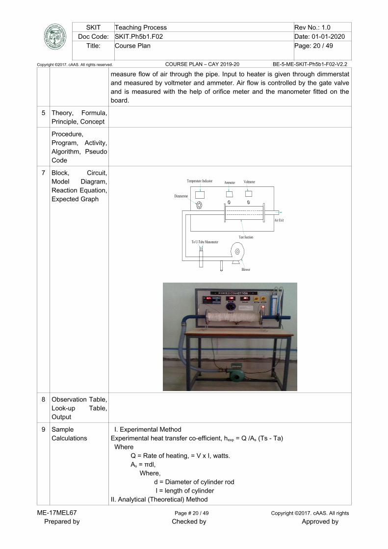
The experimental set up consists of a blower unit fitted with the test pipe. The testsection is surrounded by band heater. Seven thermocouples are embedded on thetest section and two thermo couples are placed in the air stream at the entranceand exit of the test section to measure the air inlet and outlet temperatures. Testpipe is connected to the delivery side of the blower along with the orifice to
ME-17MEL67 Page # 19 / 49 Copyright ©2017. cAAS. All rights
Prepared by Checked by Approved by
SKIT Teaching Process Rev No.: 1.0Doc Code: SKIT.Ph5b1.F02 Date: 01-01-2020
Title: Course Plan Page: 20 / 49
Copyright ©2017. cAAS. All rights reserved. COURSE PLAN – CAY 2019-20 BE-5-ME-SKIT-Ph5b1-F02-V2.2
measure flow of air through the pipe. Input to heater is given through dimmerstatand measured by voltmeter and ammeter. Air flow is controlled by the gate valveand is measured with the help of orifice meter and the manometer fitted on theboard.
5 Theory, Formula,Principle, Concept
Procedure,Program, Activity,Algorithm, PseudoCode
7 Block, Circuit,Model Diagram,Reaction Equation,Expected Graph
Ammeter
Dimmerstat
Temperature Indicator Voltmeter
Blower
Test SectionTo U-Tube Manometer
Air Exit
8 Observation Table,Look-up Table,Output
9 SampleCalculations
I. Experimental Method Experimental heat transfer co-efficient, hexp = Q /As (Ts - Ta) Where Q = Rate of heating, = V x I, watts. As = πdl, Where, d = Diameter of cylinder rod l = length of cylinder II. Analytical (Theoretical) Method
ME-17MEL67 Page # 20 / 49 Copyright ©2017. cAAS. All rights
Prepared by Checked by Approved by
SKIT Teaching Process Rev No.: 1.0Doc Code: SKIT.Ph5b1.F02 Date: 01-01-2020
Title: Course Plan Page: 21 / 49
Copyright ©2017. cAAS. All rights reserved. COURSE PLAN – CAY 2019-20 BE-5-ME-SKIT-Ph5b1-F02-V2.2
(1) Bulk mean temperature, Tf = T1+T7 / 2. ( °C ) Where, T1 = Air inlet temperature. (°C) T7 = Air outlet temperature. (°C)Properties of air at the film temperature (Tf) is obtained from data book, hencedetermine Density, ρ = Specific heat, Cp = Kinematic viscosity, ν = Thermal conductivity, k = Prandtl number, Pr (2) Discharge q = Cd A0 aHG..2
Where, Cd = Co-efficient of discharge = 0.65
A0 = 4
. 2od
do = Diameter of orifice
Ha = Head of air = w Hw/ a
w = 1000 kg/m3
a = 1.2 kg/m3
(3) Velocity v =A
q. (m/s)
(4) Reynold’s No. Re = vd / Where, d = Diameter of the cylinder, (m) v = Velocity of the air. (m/s)From heat transfer Data hand book corresponding to this value of Reynoldsnumber, the nusselt number(Nu) is given by Nu = 0.618 (Re )0.466, if 40 < Re < 4000 Nu = 0.174 (Re )0.618, if 4000 < Re < 40,000. Hence,
Nu =k
dhtheo .. Or
htheo= d
kNu..
Where, htheo = Theoretical heat transfer co-efficient, (Km
W
2 )
10 Graphs, Outputs
11 Results & Analysis Result : The co-efficient of heat transfer by experiment is
hexp =
The co-efficient of heat transfer by theoretical is
htheo =Points for Discussion :(1) List of various precautions observed during experimentation.(2)Comment upon the values of heat transfer coefficient obtained experimentally
and the one by using correlations.
ME-17MEL67 Page # 21 / 49 Copyright ©2017. cAAS. All rights
Prepared by Checked by Approved by
SKIT Teaching Process Rev No.: 1.0Doc Code: SKIT.Ph5b1.F02 Date: 01-01-2020
Title: Course Plan Page: 22 / 49
Copyright ©2017. cAAS. All rights reserved. COURSE PLAN – CAY 2019-20 BE-5-ME-SKIT-Ph5b1-F02-V2.2
12 Application Areas 2-D study state heat conduction equation is applied in CFD analysis( Finitedifference and finite element method)
13 Remarks
14s
Faculty Signaturewith Date
Experiment 06 : Determination of Emissivity of a Surface.
- ExperimentNo.:
6 Marks DatePlanned
DateConducte
d
1 Title Determination of Emissivity of a Surface.
2 Course Outcomes Determine surface emissivity of a test plate
3 Aim To determine the emissivity of grey body at temperature.
4 Material /EquipmentRequired
black body, test body, heater, digital voltmeter Ammeter, control body.
5 Theory, Formula,Principle, Concept
Thermal Radiation is the energy emitted by a body as a result of its finitetemperature. In contrast to heat transfer through convection and conduction,radiation heat transfer does not require a medium and can occur in vacuum.The amount of energy (E) emitted by the surface of a body via radiations is givenby “ Stefan Boltzmann law” as E =
Where,E = Energy emitted per unit surface of the body( Emissivepower )
σ = Stefan boltzsman constant = 5.669×10⁻⁸ . ( 42 Km
W
)
T = Absolute temperature of the surface. (K). =Emissivity of a body.Emissivity(of a body is a dimensionless number and can vary between 0 and1.A surface with =1 is called a perfect radiator and is called as a”blackbody”.For real surfaces <1. Hence Equation (1) for a black body can be writtenas Eb =
From equations (1) and (2), it follows that
=bE
E .................................... (3)
6 Procedure,Program, Activity,Algorithm, PseudoCode
(1) Switch on the heater to the black-body & adjust the power input to the heaterto suitable value using regulator.
(2) Switch on the heater to the test body & keep the power input to a value lessthan that of input to the black body.
(3) Observe the temperature of black body & test surface in closed time interval &
ME-17MEL67 Page # 22 / 49 Copyright ©2017. cAAS. All rights
Prepared by Checked by Approved by
SKIT Teaching Process Rev No.: 1.0Doc Code: SKIT.Ph5b1.F02 Date: 01-01-2020
Title: Course Plan Page: 23 / 49
Copyright ©2017. cAAS. All rights reserved. COURSE PLAN – CAY 2019-20 BE-5-ME-SKIT-Ph5b1-F02-V2.2
adjust power input to the test body heater such that both black body & testsurface temperatures are almost same.
(4) Wait till the steady state is reached, record the input power to heaters &temperature of grey body, black body & enclosure now calculate theEmissivity.
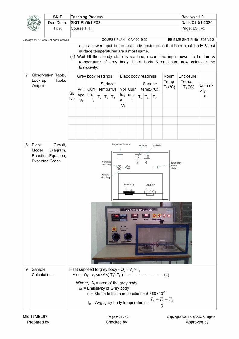
7 Observation Table,Look-up Table,Output
Sl.No
Grey body readings Black body readings RoomTempT1 (ºC)
Enclosure Temp. T8 (ºC) Emissi-
vity
Voltage V2
Current I2
Surfacetemp.(ºC) Vol
tage V1
Current I1
Surfacetemp.(ºC)
T2 T3 T4 T5 T6 T7
8 Block, Circuit,Model Diagram,Reaction Equation,Expected Graph
Ammeter
DimmerstatBlack Body
Temperature Indicator Voltmeter
DimmerstatGrey Body
TemperatureSelector Switch
Black Body Grey Body
T5 T6 T7 T3 T4T2
9 SampleCalculations
Heat supplied to grey body - Qg = Vg × Ig Also, Qg = g×σ×A×( Tg
4-T84).................................... (4)
Where, Ag = area of the grey bodyb = Emissivity of Grey body σ = Stefan boltzsman constant = 5.669×10⁻⁸.
Tg = Avg. grey body temperature = 3
432 TTT
ME-17MEL67 Page # 23 / 49 Copyright ©2017. cAAS. All rights
Prepared by Checked by Approved by

SKIT Teaching Process Rev No.: 1.0Doc Code: SKIT.Ph5b1.F02 Date: 01-01-2020
Title: Course Plan Page: 24 / 49
Copyright ©2017. cAAS. All rights reserved. COURSE PLAN – CAY 2019-20 BE-5-ME-SKIT-Ph5b1-F02-V2.2
T8 = Enclosure Temperature. Heat supplied to black body- Qb= Vb× Ib
Also, Qg = b×σ×A× ( Tb
4-T84) .................................... (5)
Where, Ab= area of the black bodyb = Emissivity of black body σ = Stefan boltzsman constant = 5.669×10 -8.
Tb = Avg. black body temperature =3
765 TTT
T8 = Enclosure Temperature.
10 Graphs, Outputs
11 Results & Analysis Result: - The experiment is successfully completed, the results tabulated intabular column. The Emissivity of given apparatus is g =
Points for Discussion :1 The value of Emissivity obtained is total is total Emissivity or
monochromatic Emissivity. What is the difference between the two.2 How and under what conditions Emissivity of a surface equals its
absorptivity.
12 Application Areas Solar flat plate collector, water heating process (solar pond), photo voltaic cell.
13 Remarks
14 Faculty Signaturewith Date
ME-17MEL67 Page # 24 / 49 Copyright ©2017. cAAS. All rights
Prepared by Checked by Approved by
SKIT Teaching Process Rev No.: 1.0Doc Code: SKIT.Ph5b1.F02 Date: 01-01-2020
Title: Course Plan Page: 25 / 49
Copyright ©2017. cAAS. All rights reserved. COURSE PLAN – CAY 2019-20 BE-5-ME-SKIT-Ph5b1-F02-V2.2
Experiment 07 : Analysis of steady and transient heat conduction, temperature distribution of planewall and cylinder using Numerical approach (ANSYS/CFD package).
- Experiment No.: 7 Marks DatePlanned
DateConducted
1 Title Determination of Overall Heat Transfer Coefficient of a Composite wall
2 Course Outcomes Understand Overall Heat Transfer Coefficient of a Composite wall
3 Aim Analysis of steady and transient heat conduction, temperature distribution of planewall and cylinder using Numerical approach (ANSYS/CFD package).
4 Material /EquipmentRequired
Given Composite wall, Heater, Set of Thermocouples, Power Supply panel,Channel Temperature Indicator and necessary connections.
5 Theory, Formula,Principle, Concept
The composition of two or more materials of different thermal conductivityarranged in series or parallel is called composite material (wall).Many engineeringapplications of practical utility involve heat transfer through composite materials.Consider for example, the wall of a refrigerator, hot cases; cold storage plants hotwater tanks, etc., which always have some kind of insulating material between theinner and outer walls. The procedure for solving one-dimensional, steady stateheat conduction problems for composite systems comprising parallel plates,coaxial cylinders or concentric spheres. It will be assumed that the parallel layersin the composite system are in perfect thermal contact or the resistance due tointerface contact is negligible, i.e, the temperature continuous at the interface oftwo layers in contact.
6 Procedure,Program, Activity,Algorithm, PseudoCode
• Switch on the mains and console.• Set the water flow rate to 1-2 lpm (Fixed).• The heat input to the heater is fixed for any desired value.• After steady state is reached, average temperature of the slabs at the
inter faces are noted. • By varying the heat input to the system through variac, different sets of
readings can be obtained. Repeat the above operations for given Heat inputs.
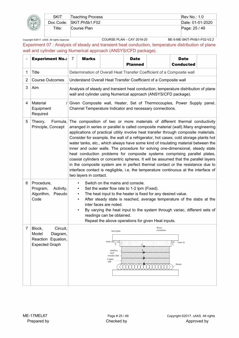
7 Block, Circuit,Model Diagram,Reaction Equation,Expected Graph
Steel plate
Copper slab
wooden slab
stainlesssteel
HeaterT2
T
T
4
8
water inwater out
Watercirculation
T9
T
T
3
5
T6
T7
ME-17MEL67 Page # 25 / 49 Copyright ©2017. cAAS. All rights
Prepared by Checked by Approved by
SKIT Teaching Process Rev No.: 1.0Doc Code: SKIT.Ph5b1.F02 Date: 01-01-2020
Title: Course Plan Page: 26 / 49
Copyright ©2017. cAAS. All rights reserved. COURSE PLAN – CAY 2019-20 BE-5-ME-SKIT-Ph5b1-F02-V2.2
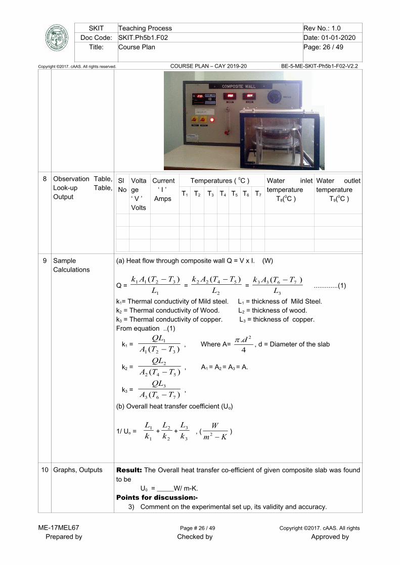
8 Observation Table,Look-up Table,Output
SlNo
Voltage‘ V ’Volts
Current ‘ I ’ Amps
Temperatures ( 0C ) Water inlettemperature T8(0C )
Water outlettemperature T9(0C )
T1 T2 T3 T4 T5 T6 T7
9 SampleCalculations
(a) Heat flow through composite wall Q = V x I. (W)
Q = 1
3211 )(
L
TTAk =
2
5422 )(
L
TTAk =
3
7633 )(
L
TTAk .............(1)
k1= Thermal conductivity of Mild steel. L1 = thickness of Mild Steel.k2 = Thermal conductivity of Wood. L2 = thickness of wood.k3 = Thermal conductivity of copper. L3 = thickness of copper. From equation ..(1)
k1 = )( 321
1
TTA
QL
, Where A=
4
. 2dd = Diameter of the slab
k2 = )( 542
2
TTA
QL
, A1 = A2 = A3 = A.
k3 = )( 763
3
TTA
QL
,
(b) Overall heat transfer coefficient (Uo)
1/ Uo = 1
1
k
L+
2
2
k
L+
3
3
k
L , (
Km
W
2 )
10 Graphs, Outputs Result: The Overall heat transfer co-efficient of given composite slab was foundto be U0 = _____W/ m-K.Points for discussion:-
3) Comment on the experimental set up, its validity and accuracy.
ME-17MEL67 Page # 26 / 49 Copyright ©2017. cAAS. All rights
Prepared by Checked by Approved by
SKIT Teaching Process Rev No.: 1.0Doc Code: SKIT.Ph5b1.F02 Date: 01-01-2020
Title: Course Plan Page: 27 / 49
Copyright ©2017. cAAS. All rights reserved. COURSE PLAN – CAY 2019-20 BE-5-ME-SKIT-Ph5b1-F02-V2.2
4) Overall heat transfer co-efficient can also be calculated without therequirement of intermediate temperatures. comment on it.
11 Results & Analysis
12 Application Areas To compute the heat flux at any location, compute the thermal stress, design ofinsulation thickness, chip temperature calculation, heat treatment of metals.
13 Remarks
14 Faculty Signaturewith Date
Experiment 08 : Determination of Steffan Boltzmann Constant.
- ExperimentNo.:
8 Marks DatePlanned
DateConducte
d
1 Title Determination of Steffan Boltzmann Constant.
2 Course Outcomes Able to determine the Stefan Boltzmann Constant.
3 Aim To determine the value of Stefan Boltzmann constant.
4 Material /EquipmentRequire
Copper hemispherical enclosure, Thermocouples jacket to hold hot water.
5 Theory, Formula,Principle, ConceptPower
The most commonly used law in radiation heat transfer between two bodies A andB is Stefan boltzman law which is given as Q = σ×A×( TA
4-TB4)
Where, Q = Heat transfer rate, W σ = Stefan boltzsman constant = 5.669×10⁻⁸. TA and TB = Temperatures of bodies A and B respectively.
The above equation is applicable to black bodies & valid only for thermal radiation. Other
type of bodies (like a glossy painted surface or a polished metal plate) do not radiate as
much energy as the black body but still the total radiation emitted flow this law.
6 Procedure,Program, Activity,Algorithm, PseudoCode
1. Switch on the main and console.2. Switch on heater.3. After water attains the maximum temperature open the valve and dump
the water to the enclosure jackets.4. Wait for few minutes to attain hemispherical atmosphere.5. Measure the enclosure temperature using channel selector.6. Insert the disc with sleeve in to the slot and record the temperature.
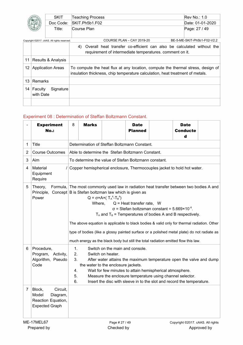
7 Block, Circuit,Model Diagram,Reaction Equation,Expected Graph
ME-17MEL67 Page # 27 / 49 Copyright ©2017. cAAS. All rights
Prepared by Checked by Approved by
SKIT Teaching Process Rev No.: 1.0Doc Code: SKIT.Ph5b1.F02 Date: 01-01-2020
Title: Course Plan Page: 28 / 49
Copyright ©2017. cAAS. All rights reserved. COURSE PLAN – CAY 2019-20 BE-5-ME-SKIT-Ph5b1-F02-V2.2
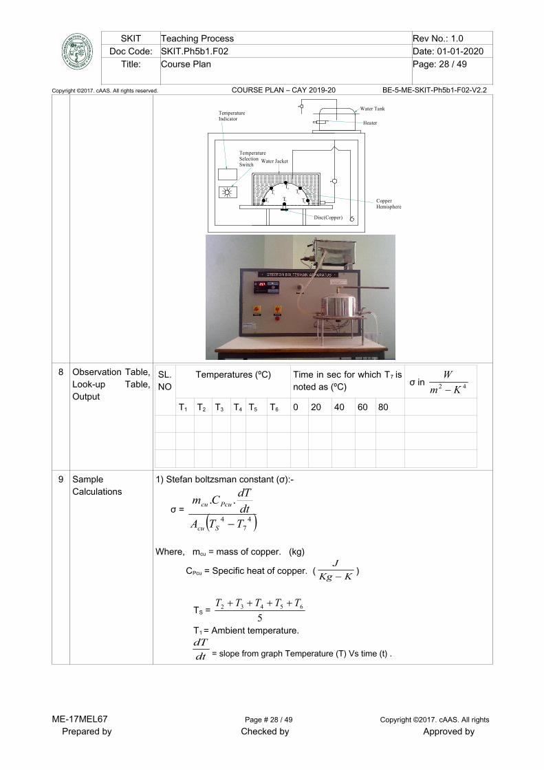
TemperatureIndicator
Water Jacket
Heater
Water Tank
TemperatureSelectionSwitch
CopperHemisphere
Disc(Copper)
T2
T3
T7
T4
T5
T6
8 Observation Table,Look-up Table,Output
SL.NO
Temperatures (ºC) Time in sec for which T7 isnoted as (ºC) σ in 42 Km
W
T1 T2 T3 T4 T5 T6 0 20 40 60 80
9 SampleCalculations
1) Stefan boltzsman constant (σ):-
σ = 4
74
..
TTAdt
dTCm
Scu
Pcucu
Where, mcu = mass of copper. (kg)
CPcu = Specific heat of copper. (KKg
J
)
TS = 5
65432 TTTTT
T1 = Ambient temperature.
dtdT
= slope from graph Temperature (T) Vs time (t) .
ME-17MEL67 Page # 28 / 49 Copyright ©2017. cAAS. All rights
Prepared by Checked by Approved by
SKIT Teaching Process Rev No.: 1.0Doc Code: SKIT.Ph5b1.F02 Date: 01-01-2020
Title: Course Plan Page: 29 / 49
Copyright ©2017. cAAS. All rights reserved. COURSE PLAN – CAY 2019-20 BE-5-ME-SKIT-Ph5b1-F02-V2.2
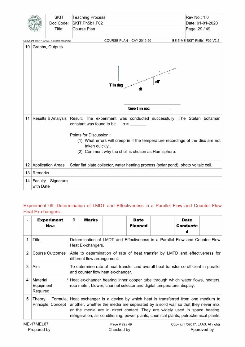
10 Graphs, Outputs
T in deg
time t in sec
dT
dt
11 Results & Analysis Result: The experiment was conducted successfully .The Stefan boltzmanconstant was found to be σ = ________
Points for Discussion :(1) What errors will creep in if the temperature recordings of the disc are not
taken quickly..(2) Comment why the shell is chosen as Hemisphere.
12 Application Areas Solar flat plate collector, water heating process (solar pond), photo voltaic cell.
13 Remarks
14 Faculty Signaturewith Date
Experiment 09 :Determination of LMDT and Effectiveness in a Parallel Flow and Counter FlowHeat Ex-changers.
- ExperimentNo.:
9 Marks DatePlanned
DateConducte
d
1 Title Determination of LMDT and Effectiveness in a Parallel Flow and Counter FlowHeat Ex-changers.
2 Course Outcomes Able to determination of rate of heat transfer by LMTD and effectiveness fordifferent flow arrangement.
3 Aim To determine rate of heat transfer and overall heat transfer co-efficient in paralleland counter flow heat ex-changer.
4 Material /EquipmentRequired
Heat ex-changer hearing inner copper tube through which water flows, heaters,rota meter, blower, channel selector and digital temperature, display.
5 Theory, Formula,Principle, Concept
Heat exchanger is a device by which heat is transferred from one medium toanother, whether the media are separated by a solid wall so that they never mix,or the media are in direct contact. They are widely used in space heating,refrigeration, air conditioning, power plants, chemical plants, petrochemical plants,
ME-17MEL67 Page # 29 / 49 Copyright ©2017. cAAS. All rights
Prepared by Checked by Approved by

SKIT Teaching Process Rev No.: 1.0Doc Code: SKIT.Ph5b1.F02 Date: 01-01-2020
Title: Course Plan Page: 30 / 49
Copyright ©2017. cAAS. All rights reserved. COURSE PLAN – CAY 2019-20 BE-5-ME-SKIT-Ph5b1-F02-V2.2
petroleum refineries, and natural gas processing.The types of heat exchangers tobe tested in the experiment are single-pass, parallel-flow and counter flowconcentric tube heat exchangers. In a parallel-flow heat exchanger, the workingfluids flow in the same direction.In the counter-flow exchanger, the fluids flow inparallel but in opposite direction.The variables that affect the performance of aheat exchanger are the fluid mass flow properties, the fluid inlet temperatures, theconfiguration, and Area and scale deposits of heat transfer surfaces.
6 Procedure,Program, Activity,Algorithm, PseudoCode
1. Allow water to circulate in inner copper tube by opening flowcontrol valve of the rota meter, monitor the flow rate.
2. Operate the valve system to make water flow either in parallel orcounter flow direction.
3. Switch on the temperature indicator and allow about 10 min. forthe temperature to become steady state is reached. Note down thetemperature.
4. Measure the water flow rate from the rotameters for both the hotand cold fluid.
5. calculate the overall heat transfer co-efficient and effectiveness forboth parallel and counter flow arrangements.
7 Observation Table,Look-up Table,Output
Sl.No
Hot Water Side Cold Water side
Flow rate(LPM)
T2 in 0C inlet
T3 in 0C outlet
Flow rate(LPM)
T4 in 0C inlet
T5 in 0C outlet
8 Block, Circuit,Model Diagram,Reaction Equation,Expected Graph
Hot fluid
Length
TemperatureT
T
T
T T
T
T
T
ho
ho
ci
ci
hi
hi
co
co
Cold fluid
q q
Cold fluid
Parallel Flow HE
Hot fluid
Cold fluid
Length
TemperatureT
T
T
T T
T
T
T
ho
ho
ci
cihi
hi
co
co
Cold fluid
q
q
Counter Flow HE
ME-17MEL67 Page # 30 / 49 Copyright ©2017. cAAS. All rights
Prepared by Checked by Approved by

SKIT Teaching Process Rev No.: 1.0Doc Code: SKIT.Ph5b1.F02 Date: 01-01-2020
Title: Course Plan Page: 31 / 49
Copyright ©2017. cAAS. All rights reserved. COURSE PLAN – CAY 2019-20 BE-5-ME-SKIT-Ph5b1-F02-V2.2
9 SampleCalculations
(1) Heat transfer rate from hot water, Qh = Cp (mh) .ΔTwh
Where, Mass flow rate (mh) = (mh in LPM) / 60, kg/sec
CP = CPc = CPh = 4184 (KKg
J
)
ΔTwh =T2 – T3
(2) Heat transfer rate from cold water, Qc = Cp (mc).ΔTwc
Where, Mass flow rate (mc) = (mc in LPM) / 60, kg/sec
CP = CPc = CPh = 4184 (KKg
J
)
ΔTwc = T5 – T4
(3) Q = 2
ch QQ
a) Log mean temperature difference ( LMTD )
LMTD =
2
1
21
lnqqqq
Where,
1q = Thi -Tci = T2 –T4
2q = Tho - Tco = T3 – T5
b) Overall Heat Transfer co-efficient (U)
ME-17MEL67 Page # 31 / 49 Copyright ©2017. cAAS. All rights
Prepared by Checked by Approved by

SKIT Teaching Process Rev No.: 1.0Doc Code: SKIT.Ph5b1.F02 Date: 01-01-2020
Title: Course Plan Page: 32 / 49
Copyright ©2017. cAAS. All rights reserved. COURSE PLAN – CAY 2019-20 BE-5-ME-SKIT-Ph5b1-F02-V2.2
U = LMTDA
Q
S , (
Km
W
2 )
Where, AS = d o.L
(6) Effectiveness ( ) = 42
32
TT
TT
(b) Counter Flow
(1) Heat transfer rate from hot water, Qh = Cp (mh) .ΔTwh
Where, Mass flow rate (mh) = (mh in LPM) / 60, kg/sec
CP = CPc = CPh = 4184 (KKg
J
)
ΔTwh =T2 – T3
(2) Heat transfer rate from cold water, Qc = Cp (mc).ΔTwc
Where, Mass flow rate (mc) = (mc in LPM) / 60, kg/sec
CP = CPc = CPh = 4184 (KKg
J
)
ΔTwc = T4– T5
, (3) Q = 2
ch QQ
(4) Log mean temperature difference (LMTD)
LMTD =
2
1
21
lnqqqq
Where,
1q = Thi -Tci = T2 –T4
2q = Tho - Tco = T3 – T5
(5) Overall Heat Transfer co-efficient (U)
ME-17MEL67 Page # 32 / 49 Copyright ©2017. cAAS. All rights
Prepared by Checked by Approved by

SKIT Teaching Process Rev No.: 1.0Doc Code: SKIT.Ph5b1.F02 Date: 01-01-2020
Title: Course Plan Page: 33 / 49
Copyright ©2017. cAAS. All rights reserved. COURSE PLAN – CAY 2019-20 BE-5-ME-SKIT-Ph5b1-F02-V2.2
U = LMTDA
Q
S
(6) Effectiveness ( ) = 52
32
TT
TT
10 Graphs, Outputs
11 Results & Analysis For Parallel Flowi) The Heat transfer obtained is ______ watts
ii) Overall Heat Transfer is _______
iii) Effectiveness is ______
For Counter Flow
1.The Heat transfer obtained is ______ watts
ii) Overall Heat Transfer is ______
iii) Effectiveness is _____
12 Application Areas LMTD and NTU methods for analysis of heat exchangers.
13 Remarks
14 Faculty Signaturewith Date
ME-17MEL67 Page # 33 / 49 Copyright ©2017. cAAS. All rights
Prepared by Checked by Approved by

SKIT Teaching Process Rev No.: 1.0Doc Code: SKIT.Ph5b1.F02 Date: 01-01-2020
Title: Course Plan Page: 34 / 49
Copyright ©2017. cAAS. All rights reserved. COURSE PLAN – CAY 2019-20 BE-5-ME-SKIT-Ph5b1-F02-V2.2
Experiment 10: Experiments on Boiling of Liquid and Condensation of Vapour.
- ExperimentNo.:
10 Marks DatePlanned
DateConducted
1 Title Experiments on Boiling of Liquid and Condensation of Vapour.
2 Course Outcomes Able to determination of heat transfer coefficient for Phase change analysis.
3 Aim To determine the average heat transfer co-efficient for film wise and dropwisecondensation and comparison of both.
4 Material /EquipmentRequired
Gas tube, steam generator copper coated internal tube, stop watch.
5 Theory, Formula,Principle, Concept
Boilers and condenser which are used as heat ex-changer posses uniquecharacteristics of heat transfer mechanism on the condensing and boiling side.When a Vapour strikes a surface temp below the corresponding saturationtemperature the Vapour will immediately condense into the liquid phase. Theporous of condensation may take place into two different type namely:
a. Film wise condensation
b. Drop wise condensation
When the condensate tends to wet the surface it is called film wise condensation.When condensate does not wet the surface and when it forms droplets on thesurface, it is known as drop wise condensation.
6 Procedure,Program, Activity,Algorithm, PseudoCode
(1) First fill the water in stainless steel tank and then switch on the main andconsole.
(2) Switch on the supply pump starter.(3) Change the ball valve position of conducting film wise condensation
experiment.(4) Switch on the heater and maintain a steady water flow, say 4LPM, through
the rota meter.(5) Wait for sometime till steady steam is generated. Then the stem is passed
through a separator to supply only dry stream to the cylinder.(6) The stem starts condensing on outer surface of the condenser tube and gets
collected as a condensate at the bottom of the cylinder.(7) Note down the different temperatures of inlet and outlet water supply, stem
pressure, flow rate of water.(8) Now change the ball valve position to drop wise condensation and conduct
the experiment for same flow rate.(9) Repeat the above procedure for different flow rates and different steam
pressures.
7 Observation Table,Look-up Table,Output
ME-17MEL67 Page # 34 / 49 Copyright ©2017. cAAS. All rights
Prepared by Checked by Approved by

SKIT Teaching Process Rev No.: 1.0Doc Code: SKIT.Ph5b1.F02 Date: 01-01-2020
Title: Course Plan Page: 35 / 49
Copyright ©2017. cAAS. All rights reserved. COURSE PLAN – CAY 2019-20 BE-5-ME-SKIT-Ph5b1-F02-V2.2
8 Block, Circuit,Model Diagram,Reaction Equation,Expected Graph
Steam inlet
Plain CondensorPlated Condensor
Glass Tube
Condensed WaterOutlet
Water inlet Water outlet
Water inlet Water outlet
T
T T
T
T
6
2 3
4
5T2
9 SampleCalculations
Specimen calculations for film-wise condensation:
Outer diameter of condensing surface = d = _______,Length of the condensing surface = L = _______,Surface temperature = TS = ________Pressure of steam condensing = _________Saturation temperature at condensing pressure = Tsat = _______ (From tables)Inlet temperature of cooling water = Twi = ______Exit temperature of cooling water = Two = ______Volume flow rate of cooling water = Vw =______Volume flow rate of condensate = Vs = Volume of steam admitted per time. = ________Mass flow rate of water = mw = w Vw = ______Specific volume of condensate = vs = vf at condensing pressure.
Condensate flow rate = msteam = s
s
v
V
Heat carried away by cooling water = Qw = mw.Cpw[ Two- Twi] = __________Heat given out by steam due to condensation = Qsteam = msteam.hfg
Mean film temperature = Tm = 2
ssat TT
Properties of condensate at Tm are: k =______ , = _______ , hfg = _____ ,
Hence, Qsteam = _________.
ME-17MEL67 Page # 35 / 49 Copyright ©2017. cAAS. All rights
Prepared by Checked by Approved by
SKIT Teaching Process Rev No.: 1.0Doc Code: SKIT.Ph5b1.F02 Date: 01-01-2020
Title: Course Plan Page: 36 / 49
Copyright ©2017. cAAS. All rights reserved. COURSE PLAN – CAY 2019-20 BE-5-ME-SKIT-Ph5b1-F02-V2.2
Condensation heat transfer co-efficient = hav = )( ssat
steam
TTdl
Q
= __________
To find hav using standard correlation:
Reynolds number for the condensate = Re = d
msteam4= _________
If Re < 1800, Condensate flow is laminar.
Hence hav =
33.0
33.0
2
23
Re
47.1
gk
= _______________ (Km
W
2 ).
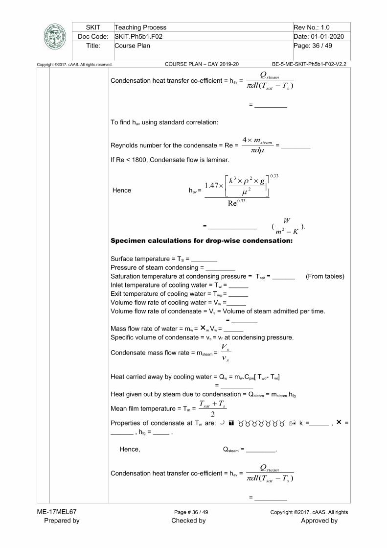
Specimen calculations for drop-wise condensation:
Surface temperature = TS = ________Pressure of steam condensing = _________Saturation temperature at condensing pressure = Tsat = _______ (From tables)Inlet temperature of cooling water = Twi = ______Exit temperature of cooling water = Two = ______Volume flow rate of cooling water = Vw =______Volume flow rate of condensate = Vs = Volume of steam admitted per time. = ________Mass flow rate of water = mw = w Vw = ______Specific volume of condensate = vs = vf at condensing pressure.
Condensate mass flow rate = msteam = s
s
v
V
Heat carried away by cooling water = Qw = mw.Cpw[ Two- Twi] = __________Heat given out by steam due to condensation = Qsteam = msteam.hfg
Mean film temperature = Tm = 2
ssat TT
Properties of condensate at Tm are: k =______ , = _______ , hfg = _____ ,
Hence, Qsteam = _________.
Condensation heat transfer co-efficient = hav = )( ssat
steam
TTdl
Q
= __________
ME-17MEL67 Page # 36 / 49 Copyright ©2017. cAAS. All rights
Prepared by Checked by Approved by
SKIT Teaching Process Rev No.: 1.0Doc Code: SKIT.Ph5b1.F02 Date: 01-01-2020
Title: Course Plan Page: 37 / 49
Copyright ©2017. cAAS. All rights reserved. COURSE PLAN – CAY 2019-20 BE-5-ME-SKIT-Ph5b1-F02-V2.2
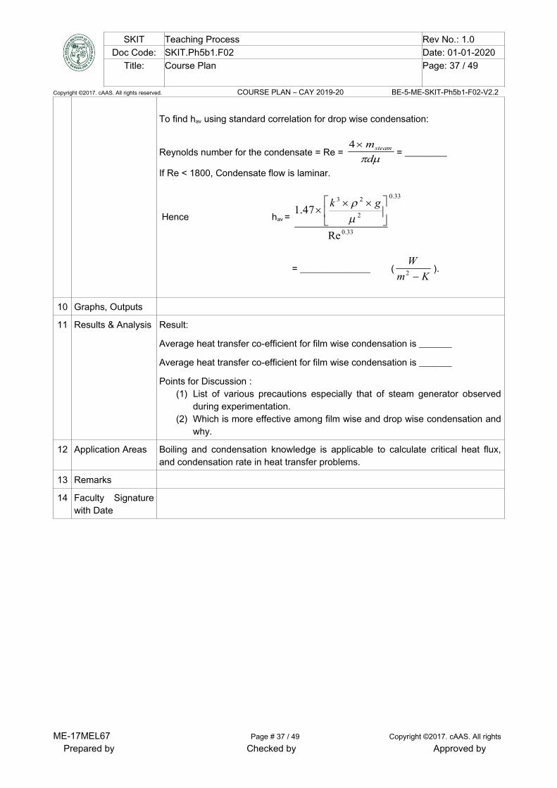
To find hav using standard correlation for drop wise condensation:
Reynolds number for the condensate = Re = d
msteam4= _________
If Re < 1800, Condensate flow is laminar.
Hence hav =
33.0
33.0
2
23
Re
47.1
gk
= _______________ (Km
W
2 ).
10 Graphs, Outputs
11 Results & Analysis Result:
Average heat transfer co-efficient for film wise condensation is _______
Average heat transfer co-efficient for film wise condensation is _______
Points for Discussion :(1) List of various precautions especially that of steam generator observed
during experimentation.(2) Which is more effective among film wise and drop wise condensation and
why.
12 Application Areas Boiling and condensation knowledge is applicable to calculate critical heat flux,and condensation rate in heat transfer problems.
13 Remarks
14 Faculty Signaturewith Date
ME-17MEL67 Page # 37 / 49 Copyright ©2017. cAAS. All rights
Prepared by Checked by Approved by

SKIT Teaching Process Rev No.: 1.0Doc Code: SKIT.Ph5b1.F02 Date: 01-01-2020
Title: Course Plan Page: 38 / 49
Copyright ©2017. cAAS. All rights reserved. COURSE PLAN – CAY 2019-20 BE-5-ME-SKIT-Ph5b1-F02-V2.2
Experiment 11 :Performance Test on a Vapour Compression Refrigeration
- ExperimentNo.:
11 Marks DatePlanned
DateConducted
1 Title Performance Test on a Vapour Compression Refrigeration
2 Course Outcomes Able to understand effect of heating and humidification on a Vapour CompressionAir – Conditioner
3 Aim To conduct a test on Vapour Compression Refrigerator and find its coefficient ofperformance.
4 Material /EquipmentRequired
Refrigerant, Compressor, Condenser, Cooling fan, Throttle valve, Capillary tube,Evaporator.
5 Theory, Formula,Principle, Concept
Refrigeration is a process by which the temperature of a given space is reducedbelow that of the atmosphere or surroundings. Refrigeration can be realized byseveral methods, for example, Ice refrigeration, Dry ice refrigeration, Evaporativerefrigeration, Air refrigeration, Vapour compression refrigeration etc. The modemrefrigeration uses the vapour compression method. In this method, a closedsystem (the refrigerant) experiences a thermodynamic cycle ; by virtue of doingnetwork on the system in such a cycle, it is possible to extract heat from a lowtemperature source (the refrigerated space) and to reject heat to a highertemperature sink (the atmosphere or cooling water). The performance of refrigerators and heat pumps is expressed in terms of thecoefficient of performance (COP), defined as
COP = inputrequired
outputDesired
.
.
6 Procedure,Program, Activity,Algorithm, PseudoCode
(a). Switch-on the Mains and the Console. (b) Keep either the Throttle Valve or the capillary Tube open-when the capillarytube is open, the throttle valve should be closed and vice versa. Both devices havethe same expansion (or throttling) effect. (c) Switch-on the motor which drives the compressor and the fan (which cools thecondenser). (d) The refrigerant passes through the vapour compression cycle as mentionedearlier resulting in cooling in the evaporator chamber or freezer. (e) Wait for about 5 minutes and note the Temperatures T1 to T5 and Pressures P1
and P2.
7 Observation Table,Look-up Table,Output
Sl.No. Pressure
upstream of
compressor
(P1) kg/cm2
Pressure
downstream of
compressor (P2)
lb/in2
Température (ºC) From p-h
curve
Enthalpy
(kJ/kg)
ME-17MEL67 Page # 38 / 49 Copyright ©2017. cAAS. All rights
Prepared by Checked by Approved by

SKIT Teaching Process Rev No.: 1.0Doc Code: SKIT.Ph5b1.F02 Date: 01-01-2020
Title: Course Plan Page: 39 / 49
Copyright ©2017. cAAS. All rights reserved. COURSE PLAN – CAY 2019-20 BE-5-ME-SKIT-Ph5b1-F02-V2.2
Compressor
Inlet
T1 = h1 =
Compressor
Outlet
T2 = h2 =
Condenser
Outlet
T3 = h3 =
Evaporator
Inlet
T4 = h4 =
8 Block, Circuit,Model Diagram,Reaction Equation,Expected Graph
9 Sample
CalculationsIn a steady state, the heat balance is given by,
QL+ Win = QH …………………. Eq (1)
QL = Heat removed by the evaporator from the refrigerated system,
= Heat gained by the refrigerant in the evaporator.
= h1 - h4 per Kg of refrigerant.
QH = Heat transferred from the refrigerant in the condenser.
= h2 - h3 per Kg of refrigerant.
Win = Work done by the compressor on the refrigerant.
= h2 – h1 per Kg of refrigerant.
h1= Enthalpy of the refrigerant at exit of the evaporator.
h2 = Enthalpy of the refrigerant at exit of the compressor.
h3 = Enthalpy of the refrigerant at exit of condenser.
h4 = Enthalpy of the refrigerant at exit of the throttle valve.
The values of enthalpies of the refrigerant at different states can be obtained fromtables/ charts using the measured values of pressures and temperatures. Thework done in the compressor can be directly obtained from the energy meter in thepanel. The co-efficient of performance (COP) of the refrigerant system is given by,
ME-17MEL67 Page # 39 / 49 Copyright ©2017. cAAS. All rights
Prepared by Checked by Approved by

SKIT Teaching Process Rev No.: 1.0Doc Code: SKIT.Ph5b1.F02 Date: 01-01-2020
Title: Course Plan Page: 40 / 49
Copyright ©2017. cAAS. All rights reserved. COURSE PLAN – CAY 2019-20 BE-5-ME-SKIT-Ph5b1-F02-V2.2
COP = in
H
W
Q=
12
41
hh
hh
.......... Eq. (2)
Where, QH = Amount of heat extracted in the refrigerator
Win= Net work done.
10 Graphs, Outputs
11 Results & Analysis Result: The COP of the refrigerator came out to be _______ .
Point for discussion
(1) Discuss the suitability of different Compressor speeds for typical dutiesand others.
(2) Can refrigerator equipment can be used as heater.If yes how it is done.
12 Application Areas Establishing temperature distribution within building, determining heat losscalculations, ventilating and air-conditioning system.
13 Remarks
14 Faculty Signaturewith Date
Experiment 12 : Air Conditioning Test Rig- Experiment
No.:12 Marks Date
PlannedDate
Conducted
1 Title Performance Test on a Vapour Compression Air – Conditioner
2 Course Outcomes Able to understand effect of heating and humidification on a Vapour CompressionAir – Conditioner
3 Aim To study the effect of Heating and humidification of air conditioning process
4 Material /EquipmentRequired
Cooling Coil, Air Heaters-2 Sets, Steam Generator, Duct
5 Theory, Formula,Principle, Concept
The science of Air Conditioning deals with maintaining a desirable internal airconditions irrespective of external atmospheric conditions. The factors involved inany air conditioning installation are: (a) Temperature (b) Humidity (c) Air movement and circulation (d) Air filtering, cleaning and purification.
The simultaneous control of these factors within the required limits isessential for human comfort or for any industrial application of the air conditioningsystem. In any air conditioning system, temperature andhumidity are controlled by thermodynamic processes. Depending on the season,the air conditioning processes involve cooling, heating, humidification anddehumidification of air. Other aspects such as air movements, circulation,purification, etc. are obtained by installing suitable fans, blowers, ducting and
ME-17MEL67 Page # 40 / 49 Copyright ©2017. cAAS. All rights
Prepared by Checked by Approved by
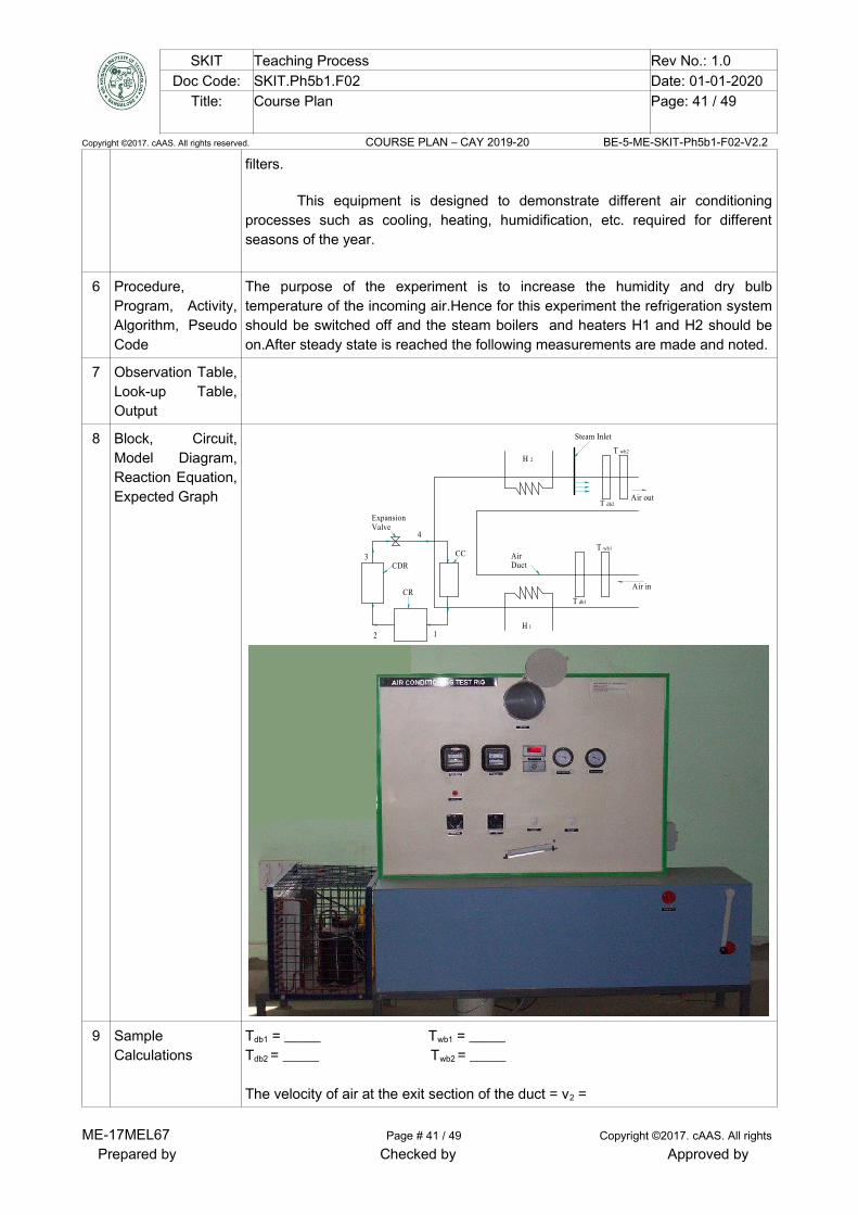
SKIT Teaching Process Rev No.: 1.0Doc Code: SKIT.Ph5b1.F02 Date: 01-01-2020
Title: Course Plan Page: 41 / 49
Copyright ©2017. cAAS. All rights reserved. COURSE PLAN – CAY 2019-20 BE-5-ME-SKIT-Ph5b1-F02-V2.2
filters.
This equipment is designed to demonstrate different air conditioningprocesses such as cooling, heating, humidification, etc. required for differentseasons of the year.
6 Procedure,Program, Activity,Algorithm, PseudoCode
The purpose of the experiment is to increase the humidity and dry bulbtemperature of the incoming air.Hence for this experiment the refrigeration systemshould be switched off and the steam boilers and heaters H1 and H2 should beon.After steady state is reached the following measurements are made and noted.
7 Observation Table,Look-up Table,Output
8 Block, Circuit,Model Diagram,Reaction Equation,Expected Graph
ExpansionValve
CDR
CR
AirDuct
Air in
Air out
12
3
4
CC
Steam Inlet
H 1
H 2
T db1
T wb1
T db2
T wb2
9 SampleCalculations
Tdb1 = _____ Twb1 = _____ Tdb2 = _____ Twb2 = _____
The velocity of air at the exit section of the duct = v2 =
ME-17MEL67 Page # 41 / 49 Copyright ©2017. cAAS. All rights
Prepared by Checked by Approved by
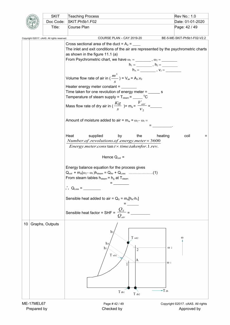
SKIT Teaching Process Rev No.: 1.0Doc Code: SKIT.Ph5b1.F02 Date: 01-01-2020
Title: Course Plan Page: 42 / 49
Copyright ©2017. cAAS. All rights reserved. COURSE PLAN – CAY 2019-20 BE-5-ME-SKIT-Ph5b1-F02-V2.2
Cross sectional area of the duct = A2 = ____ The inlet and exit conditions of the air are represented by the psychrometric chartsas shown in the figure 11.1 (a)From Psychrometric chart, we have hh
hv
Volume flow rate of air in (s
m3
) = Vair = A2.v2
Heater energy meter constant = ________Time taken for one revolution of energy meter = ______ sTemperature of steam supply = Tsteam = _____ 0C
Mass flow rate of dry air in (s
Kg )= ma =
2v
Vair =______
Amount of moisture added to air = mw = = __________.
Heat supplied by the heating coil =
..1..tan..
3600.....
revtakenfortimetconsmeterEnergy
meterenergyofsrevolutionofNumber
Hence Qcoil =
Energy balance equation for the process givesQcoil + ma(hsteam = QAir + QLoss ……………….(1)From steam tables hsteam = hg at Tsteam
= ________QLoss = _________
Sensible heat added to air = QS = ma[hA-h1] = ______
Sensible heat factor = SHF = air
S
Q
Q= __________
10 Graphs, Outputs
T db1
T wb1
T db2
T wb2
T db
1
2
A
h1
h2
hA
ME-17MEL67 Page # 42 / 49 Copyright ©2017. cAAS. All rights
Prepared by Checked by Approved by

SKIT Teaching Process Rev No.: 1.0Doc Code: SKIT.Ph5b1.F02 Date: 01-01-2020
Title: Course Plan Page: 43 / 49
Copyright ©2017. cAAS. All rights reserved. COURSE PLAN – CAY 2019-20 BE-5-ME-SKIT-Ph5b1-F02-V2.2
11 Results & Analysis Result: Sensible heat factor for heating and humidification process is___________ ,Points for Discussion :
(1) List of various precautions observed during experimentation.(2) What is dew factor.
12 Application Areas Establishing temperature distribution within building, determining heat losscalculations, ventilating and air-conditioning system.
13 Remarks
14 Faculty Signaturewith Date
Experiment 13: Experiment on Transient Conduction Heat Transfer.
- ExperimentNo.:
13 Marks DatePlanned
DateConducte
d
1 Title Experiment on Transient Conduction Heat Transfer.
2 Course Outcomes Able to determine temperature distribution and unsteady state heat conduction
3 Aim To obtain temperature profile for conduction through a cylindrical rod heated by aconstant source and to compare theoretically predicted temperature distributionunder transient conditions.
4 Material /EquipmentRequired
Transient heat conduction set-up, thermocouples, stop watch/clock.
5 Theory, Formula,Principle, Concept
A Heat transfer process which is time dependent is designated as an unsteadystate or transient heat transfer. There are large number of situations wherechanges in condition result in transient temperature distribution.Unsteady stateheat transfer generally occurs before steady state operating conditions.
Transient temperature distribution results in manufacture of bricks, Cooking andfreezing of food and in heat and cold treatment of metals.
6 Procedure,Program, Activity,Algorithm, PseudoCode
➔ Heat the metal rod(Stainless steel) by electrical heating at constant rate byadjusting the current and voltage. ➔ Adjust the flow of water to one litres/min using rota meter. Note the readings ofthe Ammeter and the Voltmeter. ➔ Note down the initial temperature at seven different positions, say at distances65mm, 130mm, 195mm etc. from the heat source. ➔ Start the stopwatch and note the temperature indicated by the Thermocouplesat a various points recorded at 5 minutes interval. ➔ Continue to note the temperatures till constant temperature is attained. Thecalculations are performed to obtain temperature profile and compared withtheoretical values obtained. ➔ Temperature profile: Theoretical temperature and experimentally observedtemperature versus distance from the hot source is drawn on a graph sheet for 15& 30 minutes time intervals.
ME-17MEL67 Page # 43 / 49 Copyright ©2017. cAAS. All rights
Prepared by Checked by Approved by

SKIT Teaching Process Rev No.: 1.0Doc Code: SKIT.Ph5b1.F02 Date: 01-01-2020
Title: Course Plan Page: 44 / 49
Copyright ©2017. cAAS. All rights reserved. COURSE PLAN – CAY 2019-20 BE-5-ME-SKIT-Ph5b1-F02-V2.2
7 Observation Table,Look-up Table,Output
Timein sec.
At distancenear Heater.X1=0 m
AtX1=.06m At
X1=.12m
AtX1=.18m
AtX1=0.24m
AtX1=.30m
AtX1=.36m
T8
T9
8 Block, Circuit,Model Diagram,Reaction Equation,Expected Graph
T1T2 T3
T4 T6 T7T5
T8
T9
Heater
Water in
waterout
0.65m 0.65m
9 SampleCalculations
Voltmeter reading V: (volts) Ammeter reading I : (amps)Total heat supplied Q = V x I = (watts)Thermal diffusivity of the material is calculated by
PC
k
, (s
m2
)
= Density of material (Copper) = 8954 3m
Kg
CP = Specific heat of material (Copper) = 381 KKg
J
k = Thermal conductivity (Copper = 386Km
W
)
A= Area of cross section of metal rod =4
. 2d = ________ m2
Where, d = Diameter of the rod in. m.
ME-17MEL67 Page # 44 / 49 Copyright ©2017. cAAS. All rights
Prepared by Checked by Approved by
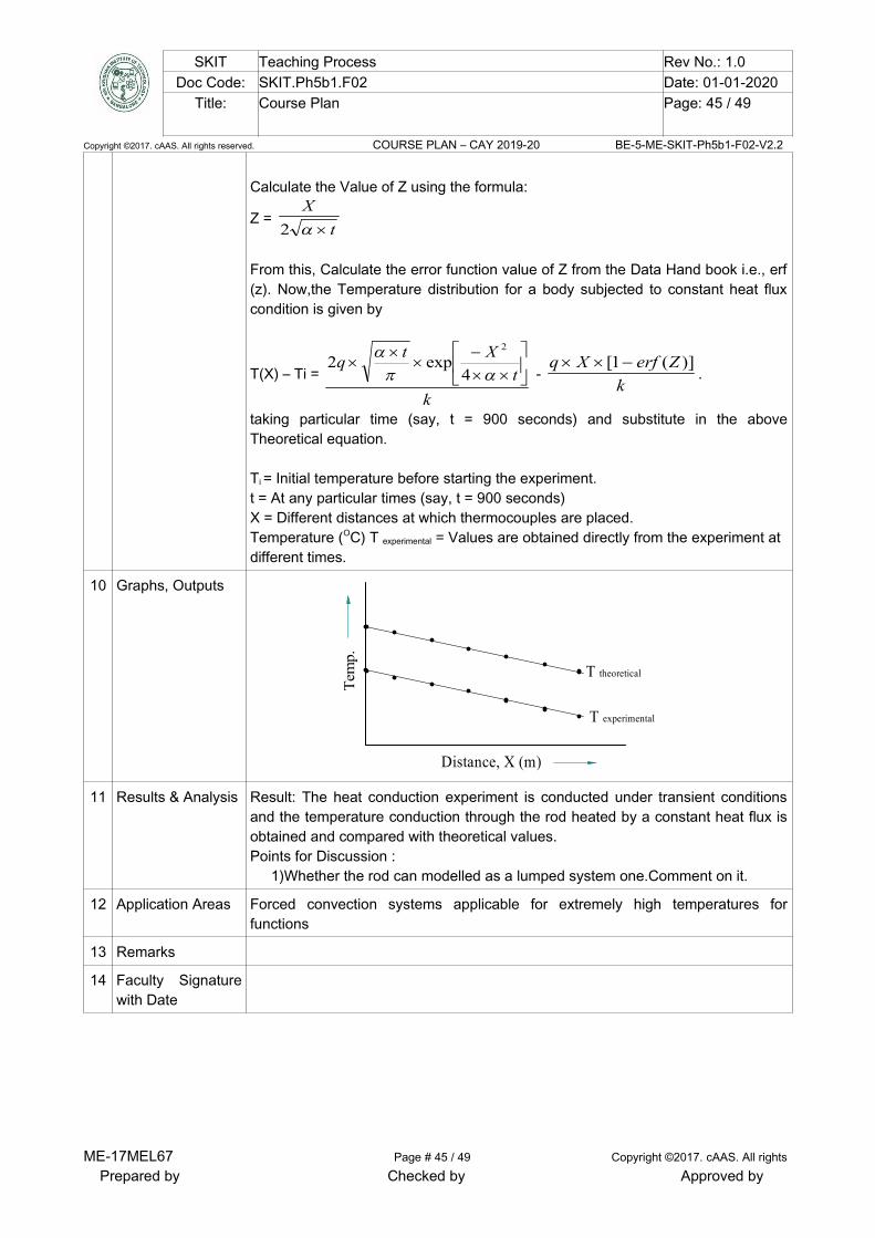
SKIT Teaching Process Rev No.: 1.0Doc Code: SKIT.Ph5b1.F02 Date: 01-01-2020
Title: Course Plan Page: 45 / 49
Copyright ©2017. cAAS. All rights reserved. COURSE PLAN – CAY 2019-20 BE-5-ME-SKIT-Ph5b1-F02-V2.2
Calculate the Value of Z using the formula:
Z = t
X
2
From this, Calculate the error function value of Z from the Data Hand book i.e., erf(z). Now,the Temperature distribution for a body subjected to constant heat fluxcondition is given by
T(X) – Ti =
k
t
Xtq
4exp2
2
- k
ZerfXq )](1[ .
taking particular time (say, t = 900 seconds) and substitute in the aboveTheoretical equation.
Ti = Initial temperature before starting the experiment. t = At any particular times (say, t = 900 seconds) X = Different distances at which thermocouples are placed. Temperature (OC) T experimental = Values are obtained directly from the experiment at different times.
10 Graphs, Outputs
Tem
p.
Distance, X (m)
T theoretical
T experimental
11 Results & Analysis Result: The heat conduction experiment is conducted under transient conditionsand the temperature conduction through the rod heated by a constant heat flux isobtained and compared with theoretical values. Points for Discussion :
1)Whether the rod can modelled as a lumped system one.Comment on it.
12 Application Areas Forced convection systems applicable for extremely high temperatures forfunctions
13 Remarks
14 Faculty Signaturewith Date
ME-17MEL67 Page # 45 / 49 Copyright ©2017. cAAS. All rights
Prepared by Checked by Approved by

SKIT Teaching Process Rev No.: 1.0Doc Code: SKIT.Ph5b1.F02 Date: 01-01-2020
Title: Course Plan Page: 46 / 49
Copyright ©2017. cAAS. All rights reserved. COURSE PLAN – CAY 2019-20 BE-5-ME-SKIT-Ph5b1-F02-V2.2
Experiment 14 : Determination of temperature distribution along a rectangular and circular finsubjected to heat loss through convection using Numerical approach (ANSYS/CFD package)
- ExperimentNo.:
14 Marks DatePlanned
DateConducted
1 Title Determination of Effectiveness on a Metallic fin.
2 Course Outcomes Estimate the effective thermal resistance and efficiency in pin-fin
3 Aim Determination of temperature distribution along a rectangular and circular finsubjected to heat loss through convection using Numerical approach(ANSYS/CFD package)
4 Material /EquipmentRequired
The experimental set up consists of a blower unit having a rectangular duct insidewhich the pin fin is fitted. One end of the pin fin is connected to heater. FiveThermocouples are embedded on the fin surface. Blower along with the orifice isused to measure flow of air through the duct. Input to heater is given throughdimmer stat and measured by voltmeter and ammeter. Air flow is controlled by thegate valve and is measured with the help of orifice meter and the manometer fittedon the board.
5 Theory, Formula,Principle, Concept
(i) Fins are extended surfaces which are used to increase the rate of heat transferbetween a surface and the adjacent fluid. Fins are classified into three viz. angularfins, straight fins and pin-fins. Angular fins are fixed to cylindrical surfaces, straightfins and pin fins are fixed to plane surfaces. Fins are used in I.C. Engines,Compresses, Radiation, Heat exchanges etc. (ii) Natural convection is the heat transfer between a surface and adjacent fluidparticles due to the macroscopic motion of fluid particles, set up by buoyancyeffect resulting from the density difference caused by their temperature difference, (iii) Fin effectiveness is the ratio of heat transfer with the fin to the heat transferwithout
fin, It is denoted by, = Pk
Ah
ml
f .
.
)tanh(
.
(iv) Fin efficiency is the ratio of heat lost from the fin to the heat that would be lostwhen the entire surface of the fin is under base temperature, it is given by η =
ml
mltanh.
6 Procedure,Program, Activity,Algorithm, PseudoCode
(a) Natural Convection: 1. Switch on the supply and adjust the variac to obtain the required heat input. 2. Note down the following readings after reaching the steady state: (i) Voltmeter reading 'V' volts(ii) Ammeter reading 'A' amps (iii) Thermocouples readings (T 1 to T 6)0C. 3. Repeat the procedure for different heat inputs and tabulate the readings.
(b) Forced Convection: 1. Switch on the supply and adjust the variac to obtain the required heat input. 2. Start the blower, set the manometer head as required. 3. Note down the following readings after reaching the steady state: (i) Voltmeter reading 'V' volts
ME-17MEL67 Page # 46 / 49 Copyright ©2017. cAAS. All rights
Prepared by Checked by Approved by

SKIT Teaching Process Rev No.: 1.0Doc Code: SKIT.Ph5b1.F02 Date: 01-01-2020
Title: Course Plan Page: 47 / 49
Copyright ©2017. cAAS. All rights reserved. COURSE PLAN – CAY 2019-20 BE-5-ME-SKIT-Ph5b1-F02-V2.2
(ii) Ammeter reading 'A' amps (iii) Thermocouples readings (T 1 to T 6)0C. (iv) Manometer reading ‘h’ cm.Repeat the procedure for different heat inputs and tabulate the readings
7 Block, Circuit,Model Diagram,Reaction Equation,Expected Graph
Pin fin
Gate valve
orificeGI Pipe
To u-TubeManometer
T T T T T1 2 3 4 5
Temperature Indicator
AmmeterVoltmeter
DimmerstatBlower
Fig 3.1(a) Pin fin apparatus
Fig 3.2(b) Pin fin enlarged
8 Observation Table,Look-up Table,Output
Sl.
No.
Voltage
( V )
Volts
Current
amps
Power
Q=VI
Watts
Temperature at differentpoint in the outer surface
of cylinder (ºC)
hthe
W/m2-K
the
(%)
exp
(%)
T2 T3 T4 T5 T6
9 SampleCalculations
(1) Experimental Efficiency of pin fin(ηexp)The efficiency of the pin fin experimentally is given by
ηexp = maxfin
fin
Q
Q
Where, Qfin = V x I, W (Qfin)max = hexp.AS.( Ts – Ta) + S.( Ts
4 – Ta4), W
But, hexp = Qfin / {As (Ts – Ta) AS = π.d.l. (m2)(2) Theoretical Efficiency of pin fin(ηthe)
ME-17MEL67 Page # 47 / 49 Copyright ©2017. cAAS. All rights
Prepared by Checked by Approved by

SKIT Teaching Process Rev No.: 1.0Doc Code: SKIT.Ph5b1.F02 Date: 01-01-2020
Title: Course Plan Page: 48 / 49
Copyright ©2017. cAAS. All rights reserved. COURSE PLAN – CAY 2019-20 BE-5-ME-SKIT-Ph5b1-F02-V2.2
ηthe = ml
mltanh
Where, m = Ak
Ph
f .
.
h = heat transfer coefficient of fin P = Perimeter of fin (D)
kf = thermal conductivity of pin fin = 110 (Km
W
)
A= Area of fin= 4
. 2d (d = Diameter of the pin fin, m), m2
l = Length of pin fin, m To find heat transfer coefficient of fin(h)
2) Film temperature, Tf =2
TaTs ( °C )
Where, Ts = Surface temperature of the cylinder =
565432 TTTTT
(K)
Ta = T1,ambient temperature (K)
Properties of air at the film temperature (T f) is obtained from data book, hence
determine
Kinematic viscosity, ν = Thermal conductivity, k =
Prandtl number, Pr =
(ii) Grassoff number Gr =2
3...
dg
Where,
β = Co-efficient of thermal expansion = )273(
1
fT. (K-l
)
∆T = Tf -T1. (K)
d = Diameter of the pin fin. (m)
ν = Kinematic viscosity. (m2 /s) Ra. No= Gr x Pr =
From heat transfer Data hand book corresponding to this value of Rayleighnumber Ra, the nusselt number(Nu) is given by
For 10-1 < Gr Pr < 104, Nu = 0.68 +444.05625.0
25.0
Pr
492.01
Pr)(67.0
Gr
For 104 < Gr Pr < 109, Nu = 0.59 (Gr x Pr)0.25
ME-17MEL67 Page # 48 / 49 Copyright ©2017. cAAS. All rights
Prepared by Checked by Approved by

SKIT Teaching Process Rev No.: 1.0Doc Code: SKIT.Ph5b1.F02 Date: 01-01-2020
Title: Course Plan Page: 49 / 49
Copyright ©2017. cAAS. All rights reserved. COURSE PLAN – CAY 2019-20 BE-5-ME-SKIT-Ph5b1-F02-V2.2
For 109 < Gr Pr < 1012, Nu = 0.13 (Gr x Pr)0.33
Hence,
Nu =k
lh.. Or
h = l
kNu..
Where, h= hthe = natural heat transfer co-efficient, (Km
W
2 )
(3) Effectiveness of Fin, Pk
Ah
ml
f .
.
)tanh(
10 Graphs, Outputs
11 Results & Analysis Result:- free convection hthe = ______ , ηexp = _______ , forced convection hthe = ______ , ηexp = _______,
Points for discussion:-(1) If the readings are taken when the steady state is yet to be reached,how willthe accuracy of the results will be affected.(2) From the observations taken in this experiment, explain how would youdetermine the thermal conductivity of the material of the fin.
12 Application Areas Buildings, Mechanical systems, Refrigeration, Spacecraft, Automotive
13 Remarks
14 Faculty Signaturewith Date
ME-17MEL67 Page # 49 / 49 Copyright ©2017. cAAS. All rights
Prepared by Checked by Approved by