Embed Size (px)
Citation preview
EC - Contract n° IST-1999-10057
EUROPEAN COMMISSION DG INFOSO
Page : 1 of 44
MOCONT REFERENCE W1SC DV 0031 27/12/01 Internal partner reference : Filing N° Doc.Type Order N° Rev.N° Date _________________________________________________________________________________________________________
SCIRO– TRIMBLE– IKERLAN – DIBE – TDT - MCC
DELIVERABLE D18
Final Report
YES NO
Distribution List : SCIRO √
TRIMBLE NAVIGATION EUROPE √
IKERLAN √
UNIVERSITY OF GENOVA – DIBE √
TERMINAL DARSENA TOSCANA √
MCC √
EUROPEAN COMMISSION – DG INFOSO √
E
D
C
B
A
27/12/2001 P. Segarich V. Recagno P
Rev. Date Drafted Checked Approved Status*
* I: Internal; R: Restricted ; IS : IST Programme participants ; FP: Framework Programme participants ; P: Public
EC - Contract n° IST-1999-10057
EUROPEAN COMMISSION DG INFOSO
Page : 2 of 44
MOCONT REFERENCE W1SC DV 0031 27/12/01 Internal partner reference : Filing N° Doc.Type Order N° Rev.N° Date _________________________________________________________________________________________________________
SCIRO– TRIMBLE– IKERLAN – DIBE – TDT - MCC
REVISION
First issue
EC - Contract n° IST-1999-10057
EUROPEAN COMMISSION DG INFOSO
Page : 3 of 44
MOCONT REFERENCE W1SC DV 0031 27/12/01 Internal partner reference : Filing N° Doc.Type Order N° Rev.N° Date _________________________________________________________________________________________________________
SCIRO– TRIMBLE– IKERLAN – DIBE – TDT - MCC
CONTENTS
1 INTRODUCTION ...................................................................................................................................................5 1.1 REFERENCE DOCUMENTS...................................................................................................................................5 1.2 ACRONYMS AND ABBREVIATIONS.....................................................................................................................6
2 OVERVIEW OF THE OBJECTIVES OF MOCONT RESEARCH PROJECT ..............................................7 2.1 SCOPE OF THE PROJECT .....................................................................................................................................7 2.2 OBJECTIVE........................................................................................................................................................7 2.3 EXPECTED RESULTS ..........................................................................................................................................8
2.3.1 The Prototype features ................................................................................................................................9 3 MOCONT GENERAL SYSTEM DESCRIPTION ............................................................................................10
3.1 STRUCTURE OF MOCONT SYSTEM ................................................................................................................10 4 GNSS LOCATION SUBSYSTEM (LOCATION MODULE)...........................................................................11
4.1 SCHEME OF THE LOCATION SYSTEM................................................................................................................11 4.1.1 Functions of the DR subsystem .................................................................................................................13 4.1.2 Functions of the GNSS subsystem .............................................................................................................14
4.2 DESCRIPTION OF THE DR SUBSYSTEM ..............................................................................................................15 4.2.1 Introduction...............................................................................................................................................15 4.2.2 Description of the DR Processing Module ................................................................................................15 4.2.3 Description of the sensors used in the DR subsystem ...............................................................................16
4.3 INTEGRATED DR/DGPS.....................................................................................................................................18 4.3.1 Introduction to Kalman Filtering ..............................................................................................................18 4.3.2 Integrated DR/DGPS implementation.......................................................................................................19
4.4 DESCRIPTION OF THE GNSS ..............................................................................................................................21 4.4.1 Base Station Installation ...........................................................................................................................21 4.4.2 Reach Stacker Installation.........................................................................................................................23 4.4.3 Software of the GNSS processing Module.................................................................................................24 4.4.4 Using the software.....................................................................................................................................24
5 VISUAL IDENTIFICATION SUBSYSTEM......................................................................................................27 5.1 HARDWARE ARCHITECTURE...........................................................................................................................27
5.1.1 Sensor and optics: constraints and feature ...............................................................................................28 5.1.2 Cabinet & Detector Equipment Housing ..................................................................................................29 5.1.3 Arm VIM....................................................................................................................................................29 5.1.4 Processing unit..........................................................................................................................................30
6 VISUAL IDENTIFICATION MODULE FUNCTIONS....................................................................................31 6.1 SWITCHING ON................................................................................................................................................31 6.2 CAMERA POSITIONING.............................................................................................................................31 6.3 ACQUISITION ..................................................................................................................................................31 6.4 DATA PROCESSING..........................................................................................................................................32
6.4.1 Software module overall description.........................................................................................................32 6.5 DATA OUTPUT.................................................................................................................................................34
7 INTERFACE WITH THE TOS...........................................................................................................................36 7.1 TOS INTERFACE .............................................................................................................................................37 7.2 DATABASE......................................................................................................................................................37 7.3 SMART SEARCH SUBSYSTEM (SSS). ................................................................................................................37 7.4 MESSAGE MANAGEMENT ................................................................................................................................38
EC - Contract n° IST-1999-10057
EUROPEAN COMMISSION DG INFOSO
Page : 4 of 44
MOCONT REFERENCE W1SC DV 0031 27/12/01 Internal partner reference : Filing N° Doc.Type Order N° Rev.N° Date _________________________________________________________________________________________________________
SCIRO– TRIMBLE– IKERLAN – DIBE – TDT - MCC
8 SYNCHRONISATION SUBSYSTEM ................................................................................................................39 8.1 INTERFACE WITH VISUAL IDENTIFICATION AND LOCATION MODULES.............................................................40 8.2 USER INTERFACE ............................................................................................................................................41
9 CONCLUSIONS....................................................................................................................................................44
FIGURES Figure 1: structure of the MOCONT system......................................................................................10 Figure 2: Scheme and flow data of the Location System ...............................................................................12 Figure 3: structure of the location system ..........................................................................................13 Figure 4: loosely coupled approach for GPS-INS integration ...........................................................13 Figure 5: View of the box of the DR Processing Module ..............................................................................15 Figure 6: Interface connectors of box of the DR Processing Module ...............................................................16 Figure 7:View of the gyroscope CFX model UCG-1 from EuroSensor ............................................................17 Figure 8:View of TGSS radar sensor mounted in a Reach Stacker ..................................................................17 Figure 9: Scheme of the wheel sensor in a Reach Stacker .............................................................................18 Figure 10: Functional Flow of DR/DGSP implementation with Extended Kalman filter .....................................20 Figure 11: Location of GPS and radio antenna ...........................................................................................21 Figure 12: Scheme of Base station installation............................................................................................22 Figure 13: Equipment on board the Reach Stacker ......................................................................................23 Figure 14: Scheme of equipment installtion on a Reach Stacker.....................................................................24 Figure 15: Position of the Reach Stacker within the container yard ..................................................25 Figure 16: Boom inclination and extension ................................................................................................25 Figure 17: Information about status of MOCONT system.............................................................................26 Figure 18: VIM hardware components ..............................................................................................27 Figure 19: Camera and optics mounted on VIM system....................................................................28 Figure 20: Detector Equipment Housing............................................................................................29 Figure 21: Graphic and visual description of arm VIM .....................................................................30 Figure 22: VIM Graphic interface, the system is waiting for input. ..................................................33 Figure 23: VIM Graphic interface, the system has received input data. ............................................34 Figure 24: Acquisition system scheme..............................................................................................35 Figure 25: MW software architecture. ...............................................................................................36 Figure 26: the whole MOCONT hardware architecture.....................................................................39 Figure 27: the Synchronisation system software architecture............................................................40 Figure 28: SCM user interface main page..........................................................................................41 Figure 29: SCM user interface, manual container ID input page.......................................................42 Figure 30: SCM user interface, manual container position input page ..............................................42 Figure 31: SCM computer installation on the RS ..............................................................................43
EC - Contract n° IST-1999-10057
EUROPEAN COMMISSION DG INFOSO
Page : 5 of 44
MOCONT REFERENCE W1SC DV 0031 27/12/01 Internal partner reference : Filing N° Doc.Type Order N° Rev.N° Date _________________________________________________________________________________________________________
SCIRO– TRIMBLE– IKERLAN – DIBE – TDT - MCC
1 INTRODUCTION
This document summarises the development of MOCONT Research Project during its two years lifetime, starting from the objectives that had been fixed at the beginning of the activities and getting to the final outcome of the research. The document has a first overview of the objectives at the beginning and then, after a brief overview of the major activities performed, a complete description of the system realised at the end of the project is presented.
1.1 REFERENCE DOCUMENTS
The following MOCONT documents are referred to: W1SC_DV_0001_C Deliverable D1 - Overall quality plan W2SC_TN_0003_B MOCONT functional specification W2SC_DV_0008_A Deliverable D4 – Overall System Requirements W7SC_TN_0024_A Preliminary Contribution to MOCONT Test Plan W2IK_TN_2001 Contribution of Ikerlan to the functional analysis of MOCONT system W2IK TN 2003 Ikerlan comments to W2SC_TN_0004_A W2SC_TN_0004_B MOCONT characterisation of the service functions W2SC_MM_0006_A Minutes of the MOCONT management meeting Genova -4th and 5th May
2000 W2SC_TN_0013 Description of the boom transducers Test (Livorno, 30th August 2000) W1SC_MM_0014 Minutes of the MOCONT management meeting -Paris 25th September 2000 W9SC_MM_0015 Minutes of the first MOCONT Workshop - Paris 26th September 2000 W5IK_DV_2011 Deliverable D9 – Location System Design W1SC_DV_0021 Deliverable D8 - Overall Architecture W3TR_DV_1007 Deliverable D6 - Location System Design W7TR_TN_1010 GNSS Hardware Description W7TR_TN_1011 GNSS Software Description W7SC_DV_0028_A Deliverable D13 – General System (Prototype) W7SC_DV_0029_A Deliverable D14 – General System Description
EC - Contract n° IST-1999-10057
EUROPEAN COMMISSION DG INFOSO
Page : 6 of 44
MOCONT REFERENCE W1SC DV 0031 27/12/01 Internal partner reference : Filing N° Doc.Type Order N° Rev.N° Date _________________________________________________________________________________________________________
SCIRO– TRIMBLE– IKERLAN – DIBE – TDT - MCC
1.2 ACRONYMS AND ABBREVIATIONS
The following acronyms are used in this document: DFD Data flow diagram TOS Terminal Operating System SSS Smart Search Subsystem LM Location Module VIM Visual Identification Module ROI Region of interest SCM Synchronisation and Communication Module DTE Data Terminal Equipment (referred to SCM, LM and VIM) DGPS Differential Global Positioning System DGNSS Differential Global Navigation Satellite System DR Dead Reckoning DTM Digital Terrain Model EKF Extended Kalman Filter GNSS Global Navigation Satellite System IMU Inertial Measurement Unit INS Inertial Navigation System GPS Global Positioning System
EC - Contract n° IST-1999-10057
EUROPEAN COMMISSION DG INFOSO
Page : 7 of 44
MOCONT REFERENCE W1SC DV 0031 27/12/01 Internal partner reference : Filing N° Doc.Type Order N° Rev.N° Date _________________________________________________________________________________________________________
SCIRO– TRIMBLE– IKERLAN – DIBE – TDT - MCC
2 OVERVIEW OF THE OBJECTIVES OF MOCONT RESEARCH PROJECT
This chapter summarises the scope of the project and its main objectives as they had been agreed between the partnership and the European Commission in the Annex 1 to the Contract, at the beginning of the project lifetime.
2.1 SCOPE OF THE PROJECT
The project deals with telematics application to intermodal transport, with particular care to the management of container terminals. Container terminals are the sites where containers can be unloaded from ships, trains or trucks to be loaded on other means of transport. Terminals are required to increase their productivity in order to face with the ever growing demand for freight transport. As it is well known, terminal operators could fulfil such a requirement through either infrastructure investments, or adding smart technologies to optimise the use of resources (i.e., personnel, machines, yard slots, etc.) currently available. Adding smart technologies may usually mean to introduce software tools (e.g., decision support or optimisation systems) to plan terminal activities. To be effective, these systems should base their operation on a reliable information set. Most terminals throughout Europe operate a Terminal Operating System (TOS), which is a software tool running on standard PC boards (sometimes on mainframes), to record the positioning of containers inside the yard and to plan handling operations. Even if these systems are well designed and implemented, they are usually fed with man-gathered information, which are often unreliable or late. This is often a cause of several problems and reduces the effectiveness of the TOS, which decreases the overall terminal logistics, and consequently reduces its performance. The extra costs due to this behaviour have been roughly estimated (for a 300.000 TEU capacity terminal) in 280.000 Euros per year. These costs are the sum of the loss in productivity for the big cranes (estimated in the 15%), some 30% of unnecessary re-handling on the yard, and cost of personnel monitoring the yard status. To recover from the problem just mentioned, the project aims at providing terminal operators with a precise knowledge of the container positioning in the yard, which could make profitable the utilisation of optimisation tools in TOS, and then to improve the terminal logistics. In the proposed project, these information are gathered from the field using a tracking system for container handling machines, integrated with a visual identification system (an automatic system reading the container identification numbers).
2.2 OBJECTIVE
At the beginning of the project, MOCONT aimed at providing a system to trace the containers in the yard in real time. Real time tracking of containers is the fundamental for any kind of decision support tool designed to better utilise container terminal resources. This problem had been partly solved in terminals equipped with huge machines only, such as Rubber Tyre (RTG) and Rail Mounted Gantry Cranes (RMG) or even Straddle Carriers, but it is still an open problem for those terminals equipped with Reach Stackers or Front Loaders. The latter are more flexible and cheaper than RTGs and RMGs are, but their productivity is usually lower as their size is. Such a high degree of flexibility makes it not cost effective to install ground-based location systems, for instance,
EC - Contract n° IST-1999-10057
EUROPEAN COMMISSION DG INFOSO
Page : 8 of 44
MOCONT REFERENCE W1SC DV 0031 27/12/01 Internal partner reference : Filing N° Doc.Type Order N° Rev.N° Date _________________________________________________________________________________________________________
SCIRO– TRIMBLE– IKERLAN – DIBE – TDT - MCC
burying tags in the ground and getting the machine location by reading the information stored in a tag through readers mounted on board of Reach Stackers and Front Loaders. At the present time, D-GNSS (Differential Global Navigation Satellite System) is certainly a good technology to get a very precise positioning in most regions of the world, and its application in the container terminal management seems to be viable, even if some major problems still occur when developing an installation. As a matter of fact, D-GNSS is already available for container terminals equipped with RTGs and RMGs, but this choice fails when such sensors are mounted on board of Reach Stackers or Front Loaders. Such a failure is due to the limits imposed to the proper propagation of the satellite signals by the containers themselves, which misleads the GNSS sensors to a wrong positioning detection, since the sensors are mounted on small machines. It is worth noting that the same conditions do not occur when the GNSS sensors are mounted over RTGs or RMGs, because of the relative position of the GNSS antenna with respect to the containers (i.e., the antenna remains always a few meters over the highest container stacks). On the other hand, the usage of dead reckoning (i.e., inertial navigation) systems is not viable as well, even if dead reckoning does not need for any satellite reference. In fact, dead reckoning systems suffer of incremental errors that need to be re-set from time to time, and these errors might be too wide in magnitude to perform the container tracing properly. The solution proposed in this project relies on the integration of D-GNSS and Inertial navigation. D-GNSS is used in nominal functioning of the system (i.e., when the satellite reference system is received properly by the sensors), whereas the dead reckoning integrates the D-GNSS during short periods of time (i.e., when some satellites are obscured by containers or satellite signals are affected by the so-called multi-path phenomenon). The integration should be the correct way to provide container terminal operators with a container tracking system. In fact, this choice does not imply any intervention on containers (e.g., the application of a tag), or a major installation of equipment on the yard (e.g., the burying of tags or wires in the soil), even if it will guarantee the precision and accuracy needed for a container yard monitoring system. Besides that, terminal operators find it useful to integrate the location system together with an Automatic Container Identification system, mounted on board of the lifter (i.e., reach stacker, front loader, transtainers, straddle carrier). The identification system is expected to be a visual one, since most terminal operators deny the application of any kind of tag (even bar codes) on containers. The container identification number should be transmitted wireless from the lifter to the control station when receiving/leaving a container from/to a truck. The identification feature could be used also during the re-handling or re-stacking operations to have an additional feedback. This feature will allow the terminal operator to track the container from the beginning to the end of transfer and stocking procedures. The system could be considered as the input to any kind of software to manage a terminal (the so-called terminal operating system), even if the partnership includes a software house to provide such a tool and the relative interfacing.
2.3 EXPECTED RESULTS
The main result of the project is a system to track automatically the containers inside a terminal from the reception to the delivery at the gate. The target is to eliminate time and personnel consuming control activities performed to check the status of the yard (i.e., the position of containers inside the yard). The system will perform the following operations:

EC - Contract n° IST-1999-10057
EUROPEAN COMMISSION DG INFOSO
Page : 9 of 44
MOCONT REFERENCE W1SC DV 0031 27/12/01 Internal partner reference : Filing N° Doc.Type Order N° Rev.N° Date _________________________________________________________________________________________________________
SCIRO– TRIMBLE– IKERLAN – DIBE – TDT - MCC
• To identify the container, by reading the container identification number, when the container is handled on receipt (i.e., when a container is unloaded from the truck, the ship or the train and handled by the stacker or the crane to leave it in the yard)
• To track any possible movement of any container in the yard, recording the slot (i.e., the position of the container in the yard – row, column, height) where the container is picked or released. The tracking operation is performed regardless of neither the handling machine used to move the container, nor the position of the container in the yard
• To communicate the container location and/or the container identity without the intervention of human operators
• To update the container locations on the terminal operating system as soon as the containers are moved inside the yard (i.e., in real time).
2.3.1 The Prototype features
The features described in the previous paragraph has been proposed in the project prototype as follows: • One prototype will be mounted on board of a reach stacker, regularly operating within the
terminal case study (Terminal Darsena Toscana in Livorno) • Identification and location of containers will be completed on board. • The identification and location of containers will be displayed on board of the reach
stacker. Information will be recorded and then transferred off-line, simulating the communication system that remains out of the project scope.
• The middleware will be implemented, in order to convert data generated by the onboard equipment into a format suitable to be put into the Terminal Operating System. The middleware will be plugged within the onboard equipment.
• Data produced by the middleware will be then loaded off-line into the Terminal Operating System, showing the coherence between information gathered from the field to those recorded in the TOS data base.
• The communication system, that will transfer information from the reach stacker to the TOS, will be designed, and market available solution to implement it will be identified and selected in terms of their characteristics and performance.
EC - Contract n° IST-1999-10057
EUROPEAN COMMISSION DG INFOSO
Page : 10 of 44
MOCONT REFERENCE W1SC DV 0031 27/12/01 Internal partner reference : Filing N° Doc.Type Order N° Rev.N° Date _________________________________________________________________________________________________________
SCIRO– TRIMBLE– IKERLAN – DIBE – TDT - MCC
3 MOCONT GENERAL SYSTEM DESCRIPTION
After having listed the objectives which had been fixed at the beginning of the activities of the research project, the intent is to expose the results obtained at the end of the project. This will let the reader get himself the feeling of how the reaching of those objectives has been persecuted and eventually achieved.
3.1 STRUCTURE OF MOCONT SYSTEM
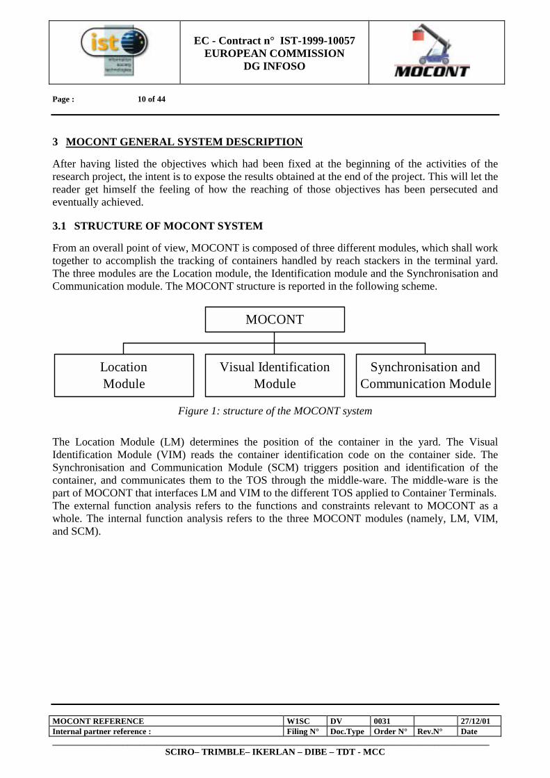
From an overall point of view, MOCONT is composed of three different modules, which shall work together to accomplish the tracking of containers handled by reach stackers in the terminal yard. The three modules are the Location module, the Identification module and the Synchronisation and Communication module. The MOCONT structure is reported in the following scheme.
Figure 1: structure of the MOCONT system
The Location Module (LM) determines the position of the container in the yard. The Visual Identification Module (VIM) reads the container identification code on the container side. The Synchronisation and Communication Module (SCM) triggers position and identification of the container, and communicates them to the TOS through the middle-ware. The middle-ware is the part of MOCONT that interfaces LM and VIM to the different TOS applied to Container Terminals. The external function analysis refers to the functions and constraints relevant to MOCONT as a whole. The internal function analysis refers to the three MOCONT modules (namely, LM, VIM, and SCM).
LocationModule
Visual IdentificationModule
Synchronisation andCommunication Module
MOCONT

EC - Contract n° IST-1999-10057
EUROPEAN COMMISSION DG INFOSO
Page : 11 of 44
MOCONT REFERENCE W1SC DV 0031 27/12/01 Internal partner reference : Filing N° Doc.Type Order N° Rev.N° Date _________________________________________________________________________________________________________
SCIRO– TRIMBLE– IKERLAN – DIBE – TDT - MCC
4 GNSS LOCATION SUBSYSTEM (LOCATION MODULE)
After summarising the architecture of the Location System, this section states the functions that the DR subsystem met. After that, the functions of the GNSS subsystem are presented.
4.1 SCHEME OF THE LOCATION SYSTEM
The Location System consists of two subsystems: the DR subsystem and the GNSS subsystem. This last one has two different parts: the GPS receiver and the GNSS Processing Module. As proposed in W3TR_DV_1007, Trimble’s Ag132 GPS receiver is used at the heart of the GNSS, and therefore of the Location System, for the positioning of the Reach Stacker. The AgGPS receiver combines high-performance GNSS reception with radio-beacon DGNSS capability in a single durable waterproof housing, ideal for use in the MOCONT environment. The receiver uses differential GNSS to provide sub-metre accuracy. Differential GNSS requires two or more receivers. One receiver, called the reference or base station, is located at a known point to determine the GNSS measurement errors. This could be housed on the roof of the main administration buildings, to allow easy access and constant monitoring. An unlimited number of AgGPS receivers, sometimes called rovers, collect GNSS data at unknown locations onboard each Reach Stacker. Over a radio band, the reference station broadcasts correction values, which are applied to the AgGPS receiver positions. Errors common at both the reference and rover receivers and then removed from the solution. The performance of the AgGPS receiver is improved by direct GNSS augmentation with height aiding. Height aiding improves the solution by enhancing satellite visibility, and reducing the positioning challenge from a three-dimensional to a two dimensional problem. Using a DTM of the port and the current location of the Reach Stacker, an interpolation algorithm provides an accurate measure of the current ground height. With knowledge of the Reach Stacker geometry, the boom extension and boom inclination, the height of the GNSS antenna on board the vehicle, and indeed the height of the container carried by the Reach Stacker can be continually computed. In addition, the Location System provides complimentary DR augmentation for periods when GNSS positioning with height aiding is not possible. The DR subsystem consists of a Processing Unit and some DR sensors, by means of which the Reach Stacker position is continuously estimated. The GNSS Processing Module continually provides the DR subsystem with the current position from the AgGPS receiver (in projected UTM coordinates) and some indication of the quality of that position fix (by means of a covariance matrix of the computed parameters). In return the DR subsystem continually updates the GNSS Processing Module with the best estimate of the current position. The GNSS Processing Module will then pass the position information to the driver and the rest of the MOCONT system.
EC - Contract n° IST-1999-10057
EUROPEAN COMMISSION DG INFOSO
Page : 12 of 44
MOCONT REFERENCE W1SC DV 0031 27/12/01 Internal partner reference : Filing N° Doc.Type Order N° Rev.N° Date _________________________________________________________________________________________________________
SCIRO– TRIMBLE– IKERLAN – DIBE – TDT - MCC
GNSSProcessing
Unit Port DTM
Ag132 GPSReceiver
DRProcessing
Unit
Display MOCONT
DR sensors
Boomsensors
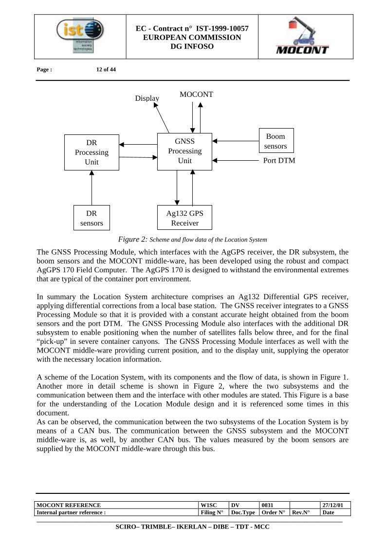
Figure 2: Scheme and flow data of the Location System
The GNSS Processing Module, which interfaces with the AgGPS receiver, the DR subsystem, the boom sensors and the MOCONT middle-ware, has been developed using the robust and compact AgGPS 170 Field Computer. The AgGPS 170 is designed to withstand the environmental extremes that are typical of the container port environment. In summary the Location System architecture comprises an Ag132 Differential GPS receiver, applying differential corrections from a local base station. The GNSS receiver integrates to a GNSS Processing Module so that it is provided with a constant accurate height obtained from the boom sensors and the port DTM. The GNSS Processing Module also interfaces with the additional DR subsystem to enable positioning when the number of satellites falls below three, and for the final “pick-up” in severe container canyons. The GNSS Processing Module interfaces as well with the MOCONT middle-ware providing current position, and to the display unit, supplying the operator with the necessary location information. A scheme of the Location System, with its components and the flow of data, is shown in Figure 1. Another more in detail scheme is shown in Figure 2, where the two subsystems and the communication between them and the interface with other modules are stated. This Figure is a base for the understanding of the Location Module design and it is referenced some times in this document. As can be observed, the communication between the two subsystems of the Location System is by means of a CAN bus. The communication between the GNSS subsystem and the MOCONT middle-ware is, as well, by another CAN bus. The values measured by the boom sensors are supplied by the MOCONT middle-ware through this bus.
EC - Contract n° IST-1999-10057
EUROPEAN COMMISSION DG INFOSO
Page : 13 of 44
MOCONT REFERENCE W1SC DV 0031 27/12/01 Internal partner reference : Filing N° Doc.Type Order N° Rev.N° Date _________________________________________________________________________________________________________
SCIRO– TRIMBLE– IKERLAN – DIBE – TDT - MCC
Gyro
RadarSensor
WheelSensor
Lap-topComputer
PC/104 DR Proc. Module
AgGPS 170 GNSS Processing Module
Ag132GPS receiver
24 V 24 V
CAN
CAN
CAN
CANRS-232
DR subsystem GNSS subsystem
MOCONT
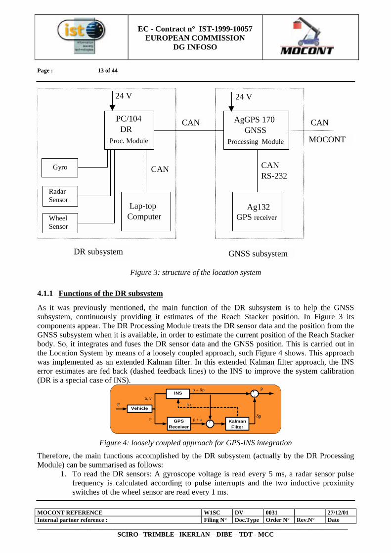
Figure 3: structure of the location system
4.1.1 Functions of the DR subsystem
As it was previously mentioned, the main function of the DR subsystem is to help the GNSS subsystem, continuously providing it estimates of the Reach Stacker position. In Figure 3 its components appear. The DR Processing Module treats the DR sensor data and the position from the GNSS subsystem when it is available, in order to estimate the current position of the Reach Stacker body. So, it integrates and fuses the DR sensor data and the GNSS position. This is carried out in the Location System by means of a loosely coupled approach, such Figure 4 shows. This approach was implemented as an extended Kalman filter. In this extended Kalman filter approach, the INS error estimates are fed back (dashed feedback lines) to the INS to improve the system calibration (DR is a special case of INS).
+-
KalmanFilter
INS
Vehicle
+-
GPSReceiver
µ+p
xδ
pp δ+
pδp
v,aF
p
Figure 4: loosely coupled approach for GPS-INS integration
Therefore, the main functions accomplished by the DR subsystem (actually by the DR Processing Module) can be summarised as follows:
1. To read the DR sensors: A gyroscope voltage is read every 5 ms, a radar sensor pulse frequency is calculated according to pulse interrupts and the two inductive proximity switches of the wheel sensor are read every 1 ms.

EC - Contract n° IST-1999-10057
EUROPEAN COMMISSION DG INFOSO
Page : 14 of 44
MOCONT REFERENCE W1SC DV 0031 27/12/01 Internal partner reference : Filing N° Doc.Type Order N° Rev.N° Date _________________________________________________________________________________________________________
SCIRO– TRIMBLE– IKERLAN – DIBE – TDT - MCC
2. To read the communication messages arrived from the GNSS subsystem. 3. To estimate from the sensor measures the vehicle heading rate, the vehicle longitudinal
speed and the vehicle status (stopped, forward or back direction), every sampling time of 5 ms.
4. To estimate the state vector from the vehicle heading rate, vehicle longitudinal speed and vehicle status, every sampling time of 5 ms.
5. If GNSS data available, to correct the position estimate by means of an Extended Kalman Filter, every sampling time of 5 ms.
6. To send the Reach Stacker position estimate data to the GNSS subsystem with a frequency of 2 Hz.
4.1.2 Functions of the GNSS subsystem
Figure 3 shows the structure and main functions of the GNSS subsystem. Basically, the GNSS Processing Module read with a frequency of 10 Hz the GPS receiver data and based on the boom sensor data, it estimates the Reach Stacker position, which is sent to the DR subsystem. The different functions accomplished by the GNSS subsystem (really by the GNSS Processing Module) can be summarised as follows:
1. To read the communication messages arrived from the MOCONT middle-ware. 2. To read the GPS data received from the GPS receiver. 3. To read the communication messages received from the DR. 4. To estimate with a frequency of 2 Hz the Reach Stacker position. 5. To send the Reach Stacker position data to the DR subsystem after estimating it. 6. To send the DR's position estimation to the MOCONT middle-ware as a response to a
request.
EC - Contract n° IST-1999-10057
EUROPEAN COMMISSION DG INFOSO
Page : 15 of 44
MOCONT REFERENCE W1SC DV 0031 27/12/01 Internal partner reference : Filing N° Doc.Type Order N° Rev.N° Date _________________________________________________________________________________________________________
SCIRO– TRIMBLE– IKERLAN – DIBE – TDT - MCC
4.2 DESCRIPTION OF THE DR SUBSYSTEM
4.2.1 Introduction
This paragraph describes the DR subsystem. As it has been stated before, it consists of the Processing Module, the required sensors and the Configuration/Monitoring Unit. Following each of the components is described in detail.
4.2.2 Description of the DR Processing Module
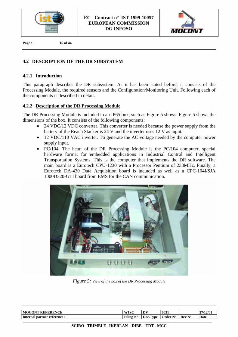
The DR Processing Module is included in an IP65 box, such as Figure 5 shows. Figure 5 shows the dimensions of the box. It consists of the following components:
• 24 VDC/12 VDC converter. This converter is needed because the power supply from the battery of the Reach Stacker is 24 V and the inverter uses 12 V as input.
• 12 VDC/110 VAC inverter. To generate the AC voltage needed by the computer power supply input.
• PC/104. The heart of the DR Processing Module is the PC/104 computer, special hardware format for embedded applications in Industrial Control and Intelligent Transportation Systems. This is the computer that implements the DR software. The main board is a Eurotech CPU-1230 with a Processor Pentium of 233MHz. Finally, a Eurotech DA-430 Data Acquisition board is included as well as a CPC-104I/SJA 1000D320-GTI board from EMS for the CAN communication.
Figure 5: View of the box of the DR Processing Module
PC/10
EC - Contract n° IST-1999-10057
EUROPEAN COMMISSION DG INFOSO
Page : 16 of 44
MOCONT REFERENCE W1SC DV 0031 27/12/01 Internal partner reference : Filing N° Doc.Type Order N° Rev.N° Date _________________________________________________________________________________________________________
SCIRO– TRIMBLE– IKERLAN – DIBE – TDT - MCC
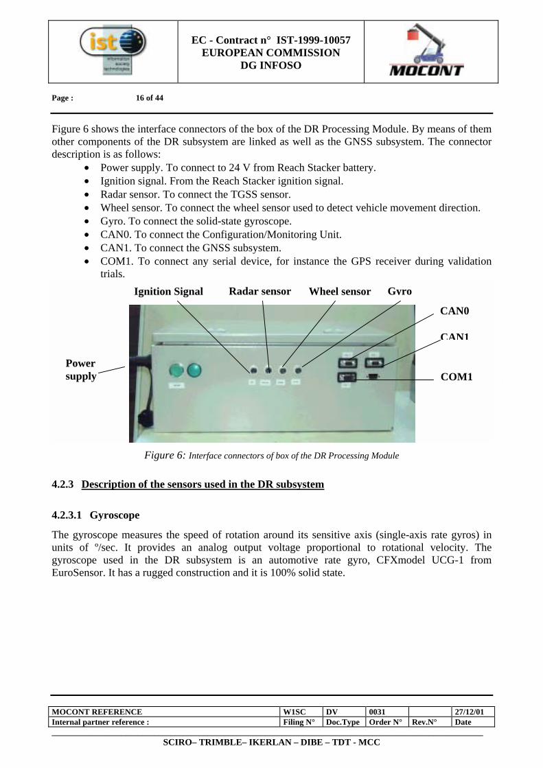
Figure 6 shows the interface connectors of the box of the DR Processing Module. By means of them other components of the DR subsystem are linked as well as the GNSS subsystem. The connector description is as follows:
• Power supply. To connect to 24 V from Reach Stacker battery. • Ignition signal. From the Reach Stacker ignition signal. • Radar sensor. To connect the TGSS sensor. • Wheel sensor. To connect the wheel sensor used to detect vehicle movement direction. • Gyro. To connect the solid-state gyroscope. • CAN0. To connect the Configuration/Monitoring Unit. • CAN1. To connect the GNSS subsystem. • COM1. To connect any serial device, for instance the GPS receiver during validation
trials.
Figure 6: Interface connectors of box of the DR Processing Module
4.2.3 Description of the sensors used in the DR subsystem
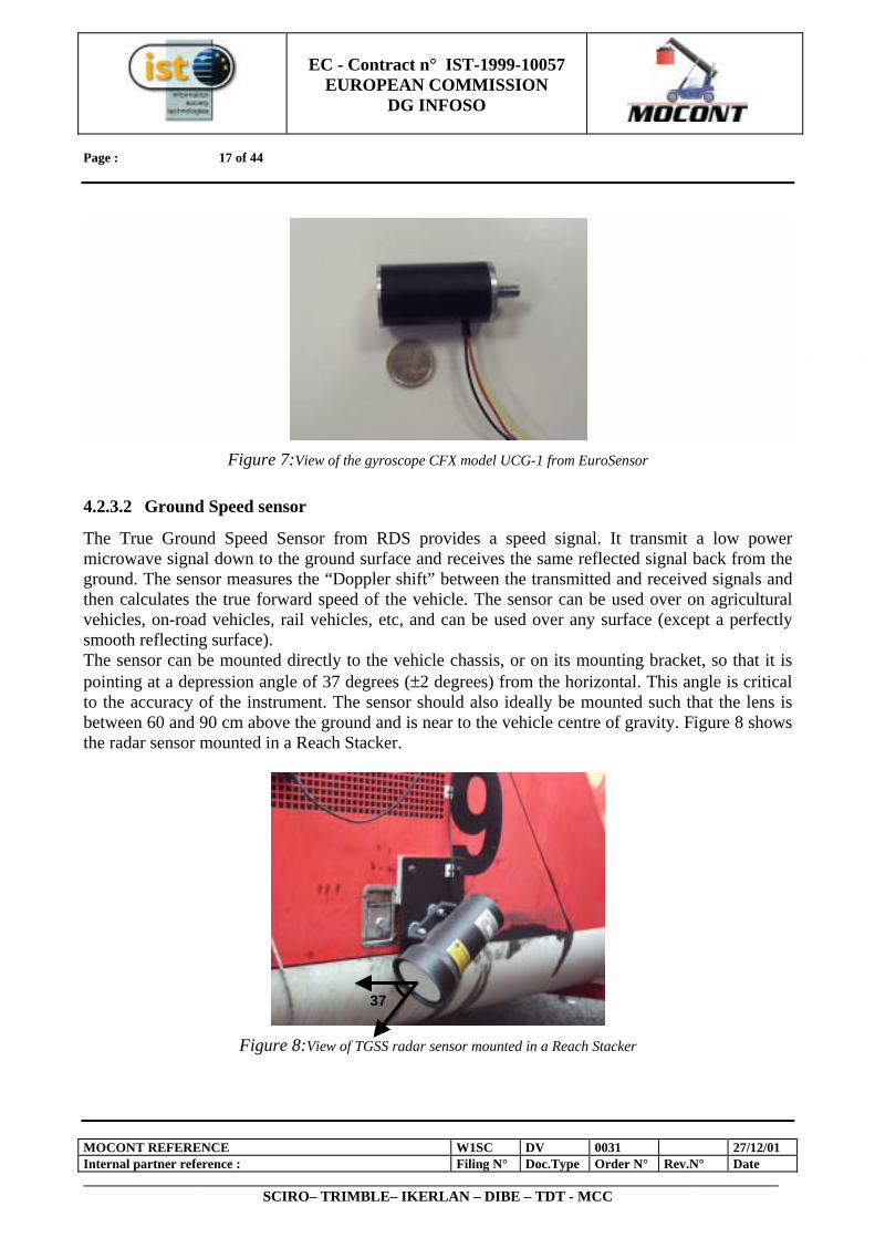
4.2.3.1 Gyroscope
The gyroscope measures the speed of rotation around its sensitive axis (single-axis rate gyros) in units of º/sec. It provides an analog output voltage proportional to rotational velocity. The gyroscope used in the DR subsystem is an automotive rate gyro, CFXmodel UCG-1 from EuroSensor. It has a rugged construction and it is 100% solid state.
PC/10
Ignition Signal Radar sensor Wheel sensor Gyro
CAN0
CAN1
COM1 Power supply
EC - Contract n° IST-1999-10057
EUROPEAN COMMISSION DG INFOSO
Page : 17 of 44
MOCONT REFERENCE W1SC DV 0031 27/12/01 Internal partner reference : Filing N° Doc.Type Order N° Rev.N° Date _________________________________________________________________________________________________________
SCIRO– TRIMBLE– IKERLAN – DIBE – TDT - MCC
Figure 7:View of the gyroscope CFX model UCG-1 from EuroSensor
4.2.3.2 Ground Speed sensor
The True Ground Speed Sensor from RDS provides a speed signal. It transmit a low power microwave signal down to the ground surface and receives the same reflected signal back from the ground. The sensor measures the “Doppler shift” between the transmitted and received signals and then calculates the true forward speed of the vehicle. The sensor can be used over on agricultural vehicles, on-road vehicles, rail vehicles, etc, and can be used over any surface (except a perfectly smooth reflecting surface). The sensor can be mounted directly to the vehicle chassis, or on its mounting bracket, so that it is pointing at a depression angle of 37 degrees (±2 degrees) from the horizontal. This angle is critical to the accuracy of the instrument. The sensor should also ideally be mounted such that the lens is between 60 and 90 cm above the ground and is near to the vehicle centre of gravity. Figure 8 shows the radar sensor mounted in a Reach Stacker.
Figure 8:View of TGSS radar sensor mounted in a Reach Stacker
PC/10
37
EC - Contract n° IST-1999-10057
EUROPEAN COMMISSION DG INFOSO
Page : 18 of 44
MOCONT REFERENCE W1SC DV 0031 27/12/01 Internal partner reference : Filing N° Doc.Type Order N° Rev.N° Date _________________________________________________________________________________________________________
SCIRO– TRIMBLE– IKERLAN – DIBE – TDT - MCC
The sensor output is calibrated at 128.52 pulses per metre travelled. The normal RDS convention is that the “speed sensor factor” is the distance travelled over two intervals between sensor pulses.
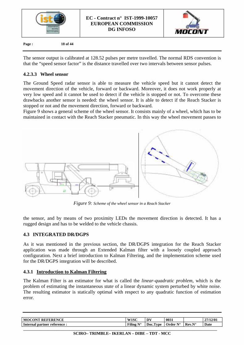
4.2.3.3 Wheel sensor
The Ground Speed radar sensor is able to measure the vehicle speed but it cannot detect the movement direction of the vehicle, forward or backward. Moreover, it does not work properly at very low speed and it cannot be used to detect if the vehicle is stopped or not. To overcome these drawbacks another sensor is needed: the wheel sensor. It is able to detect if the Reach Stacker is stopped or not and the movement direction, forward or backward. Figure 9 shows a general scheme of the wheel sensor. It consists mainly of a wheel, which has to be maintained in contact with the Reach Stacker pneumatic. In this way the wheel movement passes to
the sensor, and by means of two proximity LEDs the movement direction is detected. It has a rugged design and has to be welded to the vehicle chassis.
4.3 INTEGRATED DR/DGPS
As it was mentioned in the previous section, the DR/DGPS integration for the Reach Stacker application was made through an Extended Kalman filter with a loosely coupled approach configuration. Next a brief introduction to Kalman Filtering, and the implementation scheme used for the DR/DGPS integration will be described.
4.3.1 Introduction to Kalman Filtering
The Kalman Filter is an estimator for what is called the linear-quadratic problem, which is the problem of estimating the instantaneous state of a linear dynamic system perturbed by white noise. The resulting estimator is statically optimal with respect to any quadratic function of estimation error.
Figure 9: Scheme of the wheel sensor in a Reach Stacker
PC/104

EC - Contract n° IST-1999-10057
EUROPEAN COMMISSION DG INFOSO
Page : 19 of 44
MOCONT REFERENCE W1SC DV 0031 27/12/01 Internal partner reference : Filing N° Doc.Type Order N° Rev.N° Date _________________________________________________________________________________________________________
SCIRO– TRIMBLE– IKERLAN – DIBE – TDT - MCC
A Kalman Filter maintains two types of variables: 1. Estimated State Vector
The components of the estimated state vector include the following: a. The variables of interest (i.e., what we want or need to know, such as position and velocity). b. "Nuisance variables" that are of no intrinsic interest but may be necessary to the estimation
process. c. The Kalman Filter state variables for a specific application must include all those system
dynamic variables that are measurable by the sensors used in that application. For example, a Kalman Filter for a system containing accelerometers and rate gyroscopes must contain acceleration and rotation rate components to which these instruments respond.
2. Covariance Matrix
It is a Measure of Estimation Uncertainty. The equations used to propagate the covariance matrix (called the Riccati equation) model and manage uncertainty, taking into account how sensor noise and dynamic uncertainty contribute to uncertainty about the estimated system rate.
By maintaining an estimate of its own estimation uncertainty and the relative uncertainty in the various sensor outputs, the Kalman Filter is able to combine all sensor information "optimally", in the sense that the resulting estimate minimises any quadratic loss function of estimation error, including the mean-squared value of any linear combination of state estimation errors. The Kalman gain is the optimal weighting matrix for combining new sensor data with a prior estimate to obtain a new estimate. The Kalman Filter is a two-step process; the steps are called prediction and correction. The correction step makes correction to an estimate, based on new information obtained from sensor measurements. The Kalman gain matrix K is the basic element of Kalman filtering. All the effort of solving the matrix Riccati equation is for the only purpose of computing the "optimal" value of the gain matrix K used for correcting an estimate x) . The first approach to Kalman filtering for non-linear systems is the Linearized Kalman Filter that uses linearization of the system model about a nominal trajectory. This is the simplest approach to Kalman filtering, but in order to deal with the non-linealities of the system the Extended Kalman Filter was developed. This filter takes into account the non-linear equations of the system model and is the one that has been used in the DR/DGPS integration for the Reach Stacker application.
4.3.2 Integrated DR/DGPS implementation
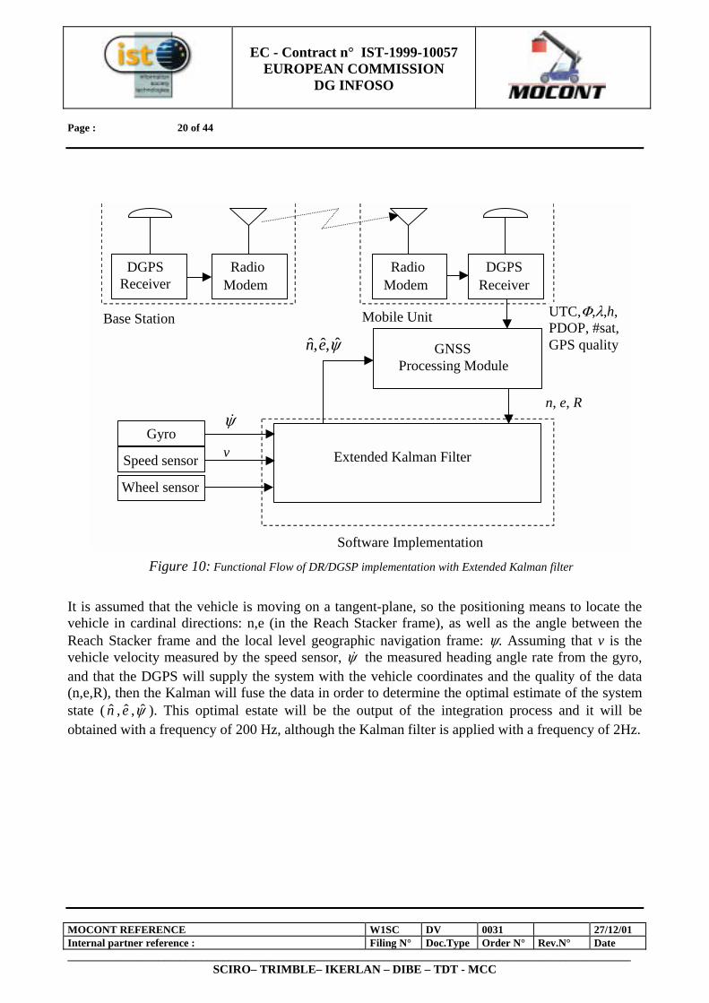
This section describes the model used for the DR/DGPS integration, although the DGPS data comes from the GNSS subsystem, which picks up them from the DGPS receiver and treats them before sending. The DR structure appears in previous sections and the DR sensors have been described. A very simple sensor scheme is used, consisting of three different sensors: a low cost gyro, a Ground Speed sensor and a wheel sensor. The wheel sensor is only used for detecting if the vehicle is stopped or not, as well as the movement direction, forward or backward because due to the characteristics of the Ground Speed sensor, it is necessary to know if the vehicle is stopped or not, as well as the vehicle direction. The integrated DR/DGPAS implementation functional flow is shown in Figure 10. This Figure shows the base and mobile receivers, and the radio modem link between them.
EC - Contract n° IST-1999-10057
EUROPEAN COMMISSION DG INFOSO
Page : 20 of 44
MOCONT REFERENCE W1SC DV 0031 27/12/01 Internal partner reference : Filing N° Doc.Type Order N° Rev.N° Date _________________________________________________________________________________________________________
SCIRO– TRIMBLE– IKERLAN – DIBE – TDT - MCC
It is assumed that the vehicle is moving on a tangent-plane, so the positioning means to locate the vehicle in cardinal directions: n,e (in the Reach Stacker frame), as well as the angle between the Reach Stacker frame and the local level geographic navigation frame: ψ. Assuming that v is the vehicle velocity measured by the speed sensor, ψ& the measured heading angle rate from the gyro, and that the DGPS will supply the system with the vehicle coordinates and the quality of the data (n,e,R), then the Kalman will fuse the data in order to determine the optimal estimate of the system state ( n , e ,ψ ). This optimal estate will be the output of the integration process and it will be obtained with a frequency of 200 Hz, although the Kalman filter is applied with a frequency of 2Hz.
DGPSReceiver
RadioModem
RadioModem
Gyro
Speed sensor
Wheel sensor
Extended Kalman Filter
GNSSProcessing Module
n, e, R
UTC,Φ,λ,h,PDOP, #sat,GPS quality
ψ&
v
ψ,ˆ,ˆ en
DGPSReceiver
Base Station Mobile Unit
Software Implementation Figure 10: Functional Flow of DR/DGSP implementation with Extended Kalman filter
EC - Contract n° IST-1999-10057
EUROPEAN COMMISSION DG INFOSO
Page : 21 of 44
MOCONT REFERENCE W1SC DV 0031 27/12/01 Internal partner reference : Filing N° Doc.Type Order N° Rev.N° Date _________________________________________________________________________________________________________
SCIRO– TRIMBLE– IKERLAN – DIBE – TDT - MCC
4.4 DESCRIPTION OF THE GNSS
This subchapter describes the GNSS hardware component of the location module of MOCONT. There are essentially two areas; the base station installation at TDT, Livorno, Italy, and the equipment installation on board the reach stacker. Since the base station was used throughout the MOCONT trials and demonstrations to transmit differential GNSS corrections, its precise coordination is also described in the document.
4.4.1 Base Station Installation
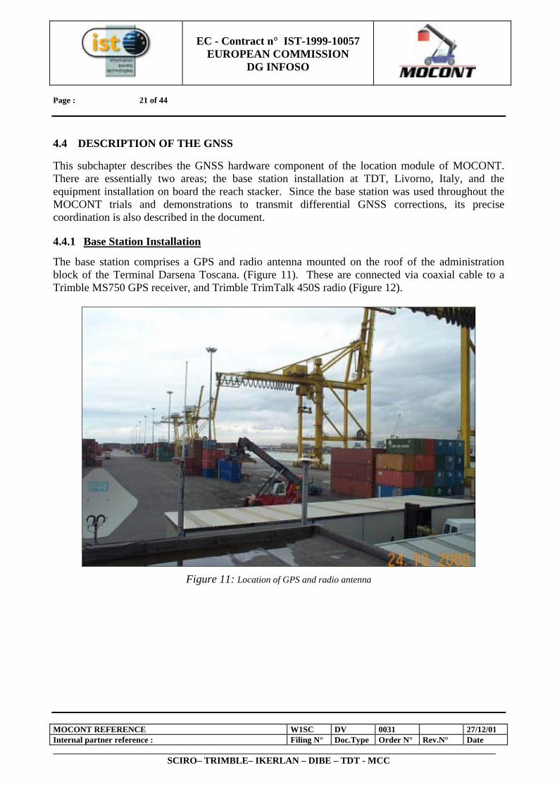
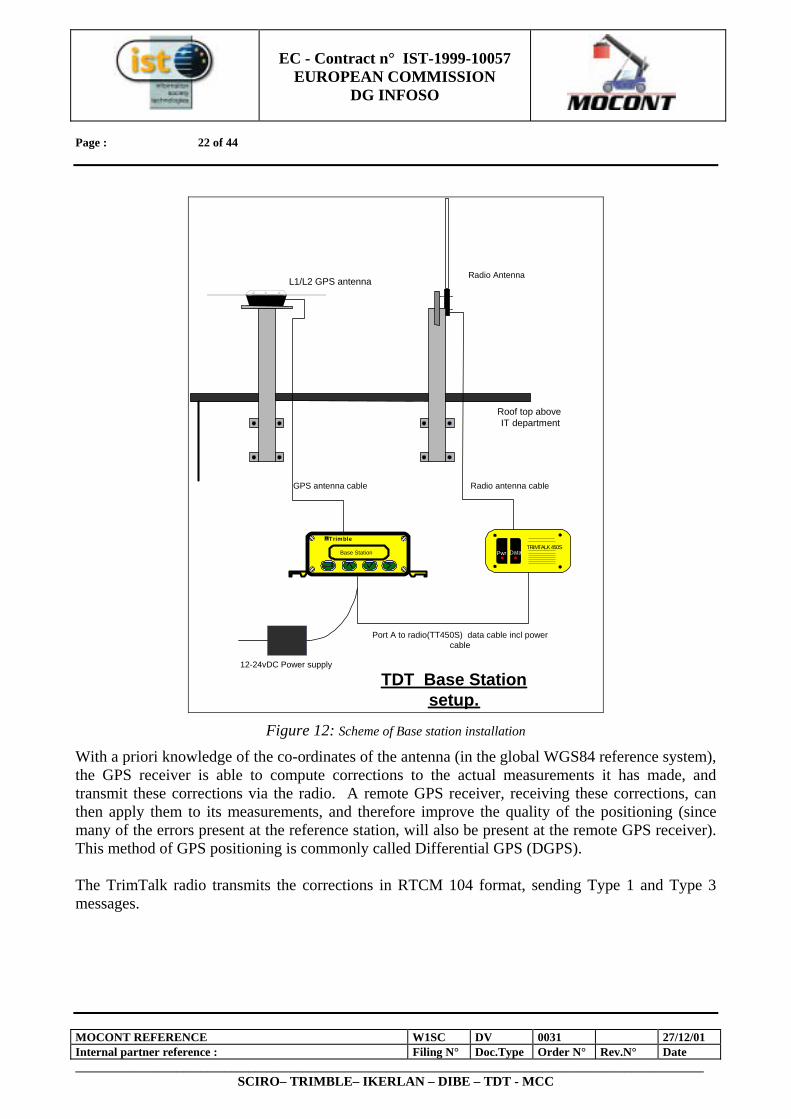
The base station comprises a GPS and radio antenna mounted on the roof of the administration block of the Terminal Darsena Toscana. (Figure 11). These are connected via coaxial cable to a Trimble MS750 GPS receiver, and Trimble TrimTalk 450S radio (Figure 12).
Figure 11: Location of GPS and radio antenna
EC - Contract n° IST-1999-10057
EUROPEAN COMMISSION DG INFOSO
Page : 22 of 44
MOCONT REFERENCE W1SC DV 0031 27/12/01 Internal partner reference : Filing N° Doc.Type Order N° Rev.N° Date _________________________________________________________________________________________________________
SCIRO– TRIMBLE– IKERLAN – DIBE – TDT - MCC
TRIMTALK 450SDataPwr
Trimble
Base Station
GPS antenna cable
Port A to radio(TT450S) data cable incl powercable
12-24vDC Power supply
Radio Antenna
TDT Base Stationsetup.
Roof top above IT department
L1/L2 GPS antenna
Radio antenna cable
Figure 12: Scheme of Base station installation
With a priori knowledge of the co-ordinates of the antenna (in the global WGS84 reference system), the GPS receiver is able to compute corrections to the actual measurements it has made, and transmit these corrections via the radio. A remote GPS receiver, receiving these corrections, can then apply them to its measurements, and therefore improve the quality of the positioning (since many of the errors present at the reference station, will also be present at the remote GPS receiver). This method of GPS positioning is commonly called Differential GPS (DGPS). The TrimTalk radio transmits the corrections in RTCM 104 format, sending Type 1 and Type 3 messages.
EC - Contract n° IST-1999-10057
EUROPEAN COMMISSION DG INFOSO
Page : 23 of 44
MOCONT REFERENCE W1SC DV 0031 27/12/01 Internal partner reference : Filing N° Doc.Type Order N° Rev.N° Date _________________________________________________________________________________________________________
SCIRO– TRIMBLE– IKERLAN – DIBE – TDT - MCC
4.4.2 Reach Stacker Installation
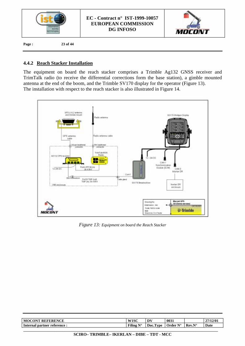
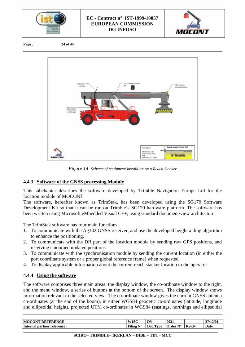
The equipment on board the reach stacker comprises a Trimble Ag132 GNSS receiver and TrimTalk radio (to receive the differential corrections form the base station), a gimble mounted antenna at the end of the boom, and the Trimble SV170 display for the operator (Figure 13). The installation with respect to the reach stacker is also illustrated in Figure 14.
Figure 13: Equipment on board the Reach Stacker
EC - Contract n° IST-1999-10057
EUROPEAN COMMISSION DG INFOSO
Page : 24 of 44
MOCONT REFERENCE W1SC DV 0031 27/12/01 Internal partner reference : Filing N° Doc.Type Order N° Rev.N° Date _________________________________________________________________________________________________________
SCIRO– TRIMBLE– IKERLAN – DIBE – TDT - MCC
Figure 14: Scheme of equipment installtion on a Reach Stacker
4.4.3 Software of the GNSS processing Module
This subchapter describes the software developed by Trimble Navigation Europe Ltd for the location module of MOCONT. The software, hereafter known as TrimStak, has been developed using the SG170 Software Development Kit so that it can be run on Trimble’s SG170 hardware platform. The software has been written using Microsoft eMbedded Visual C++, using standard document/view architecture. The TrimStak software has four main functions: 1. To communicate with the Ag132 GNSS receiver, and use the developed height aiding algorithm
to enhance the positioning. 2. To communicate with the DR part of the location module by sending raw GPS positions, and
receiving smoothed updated positions. 3. To communicate with the synchronisation module by sending the current location (in either the
port coordinate system or a proper global reference frame) when requested. 4. To display applicable information about the current reach stacker location to the operator.
4.4.4 Using the software
The software comprises three main areas: the display window, the co-ordinate window to the right, and the menu window, a series of buttons at the bottom of the screen. The display window shows information relevant to the selected view. The co-ordinate window gives the current GNSS antenna co-ordinates (at the end of the boom), in either WGS84 geodetic co-ordinates (latitude, longitude and ellipsoidal height), projected UTM co-ordinates in WGS84 (eastings, northings and ellipsoidal
EC - Contract n° IST-1999-10057
EUROPEAN COMMISSION DG INFOSO
Page : 25 of 44
MOCONT REFERENCE W1SC DV 0031 27/12/01 Internal partner reference : Filing N° Doc.Type Order N° Rev.N° Date _________________________________________________________________________________________________________
SCIRO– TRIMBLE– IKERLAN – DIBE – TDT - MCC
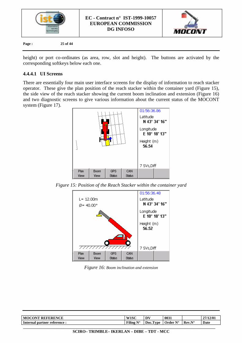
height) or port co-ordinates (as area, row, slot and height). The buttons are activated by the corresponding softkeys below each one.
4.4.4.1 UI Screens
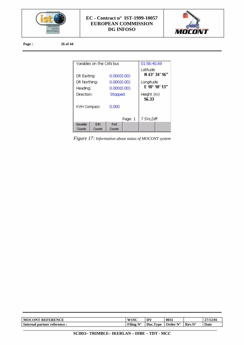
There are essentially four main user interface screens for the display of information to reach stacker operator. These give the plan position of the reach stacker within the container yard (Figure 15), the side view of the reach stacker showing the current boom inclination and extension (Figure 16) and two diagnostic screens to give various information about the current status of the MOCONT system (Figure 17).
Figure 15: Position of the Reach Stacker within the container yard
Figure 16: Boom inclination and extension
EC - Contract n° IST-1999-10057
EUROPEAN COMMISSION DG INFOSO
Page : 26 of 44
MOCONT REFERENCE W1SC DV 0031 27/12/01 Internal partner reference : Filing N° Doc.Type Order N° Rev.N° Date _________________________________________________________________________________________________________
SCIRO– TRIMBLE– IKERLAN – DIBE – TDT - MCC
Figure 17: Information about status of MOCONT system

EC - Contract n° IST-1999-10057
EUROPEAN COMMISSION DG INFOSO
Page : 27 of 44
MOCONT REFERENCE W1SC DV 0031 27/12/01 Internal partner reference : Filing N° Doc.Type Order N° Rev.N° Date _________________________________________________________________________________________________________
SCIRO– TRIMBLE– IKERLAN – DIBE – TDT - MCC
5 VISUAL IDENTIFICATION SUBSYSTEM
In this chapter the final architecture of the visual identification module is presented. The hardware components are described in this first section.
5.1 HARDWARE ARCHITECTURE
The VIM hardware components are classified in five different categories: • Sensor and Optics: all the vision equipment that is the camera and its optics; • Cabinet & Detector Equipment Housing ; • Camera support framework (here after named Arm VIM); • Processing unit: a vehicular - industrial PC; • Communication unit: Net card; • Wiring;
In Figure 18 the relations between those components are shown.
Figure 18: VIM hardware components
All these elements co-operate to acquire a frame sequence of the container, to transform it into an analogue signal, and to allocate the “best” container frame to a data buffer on the PC RAM. They have been selected during the design phase, depending on the VIM objectives and all the external constraints. The overall system will be mounted on the reach stacker: the processing unit on the rear of the vehicle cabin, while arm VIM on the spreader.
PROCESSING UNIT
ARM VIM
CAMERA, OPTICS, HOUSING MECHANICS, PNEUMATICS, SENSORS
FRAME GRABBER NET CARD, µPROCESSOR
CONNECTION CABLE TCP/IP CONNECTION
EC - Contract n° IST-1999-10057
EUROPEAN COMMISSION DG INFOSO
Page : 28 of 44
MOCONT REFERENCE W1SC DV 0031 27/12/01 Internal partner reference : Filing N° Doc.Type Order N° Rev.N° Date _________________________________________________________________________________________________________
SCIRO– TRIMBLE– IKERLAN – DIBE – TDT - MCC
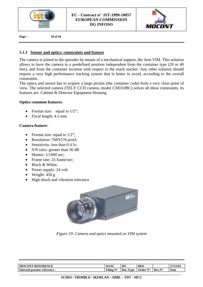
5.1.1 Sensor and optics: constraints and feature
The camera is joined to the spreader by means of a mechanical support, the Arm VIM. This solution allows to have the camera in a predefined position independent from the container type (20 or 40 feet), and from the container location with respect to the reach stacker. Any other solution should require a very high performance tracking system that is better to avoid, according to the overall constraints. The optics and sensor has to acquire a large picture (the container code) from a very close point of view. The selected camera (TELY CCD camera, model CS8310BC) solves all these constraints, its features are: Cabinet & Detector Equipment Housing Optics common features:
• Format size: equal to 1/2”; • Focal length: 4.5 mm.
Camera feature:
• Format size: equal to 1/2”; • Resolution: 768X576 pixel; • Sensitivity: less than 0.4 lx; • S/N ratio: greater than 56 dB • Shutter: 1/1000 sec; • Frame rate: 25 frame/sec; • Black & White; • Power supply: 24 volt • Weight: 450 g • High shock and vibration tolerance
Figure 19: Camera and optics mounted on VIM system
EC - Contract n° IST-1999-10057
EUROPEAN COMMISSION DG INFOSO
Page : 29 of 44
MOCONT REFERENCE W1SC DV 0031 27/12/01 Internal partner reference : Filing N° Doc.Type Order N° Rev.N° Date _________________________________________________________________________________________________________
SCIRO– TRIMBLE– IKERLAN – DIBE – TDT - MCC
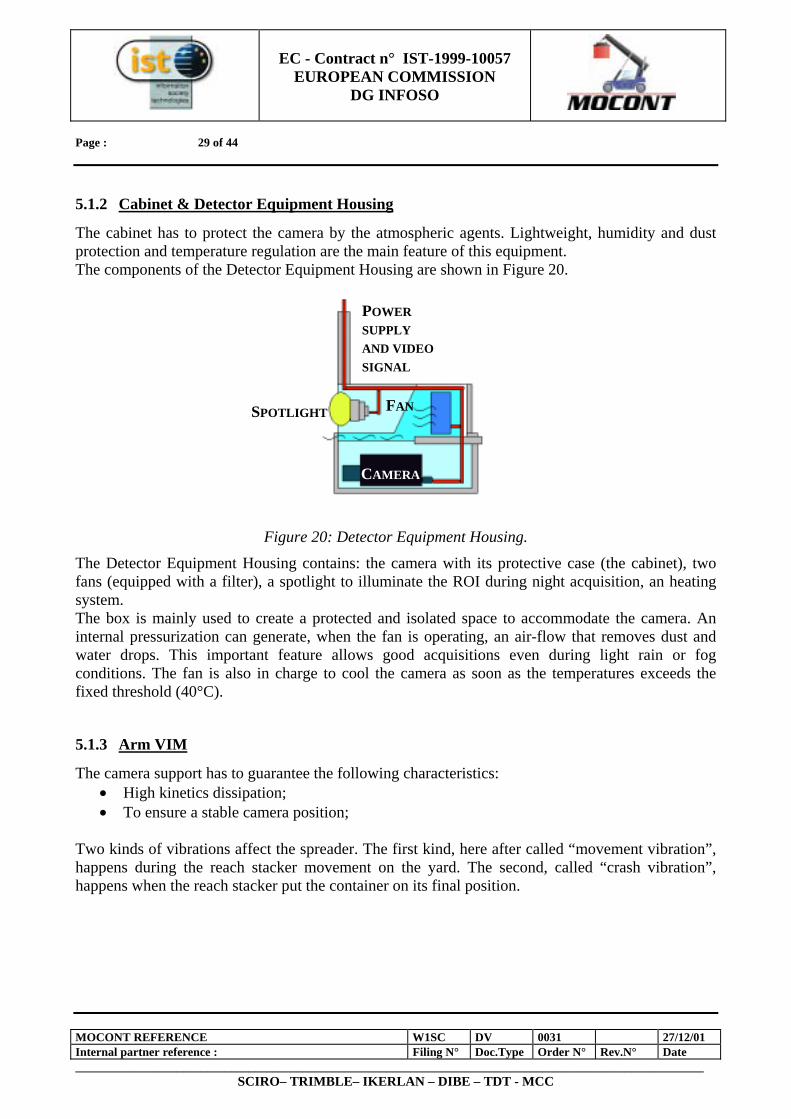
5.1.2 Cabinet & Detector Equipment Housing
The cabinet has to protect the camera by the atmospheric agents. Lightweight, humidity and dust protection and temperature regulation are the main feature of this equipment. The components of the Detector Equipment Housing are shown in Figure 20.
Figure 20: Detector Equipment Housing.
The Detector Equipment Housing contains: the camera with its protective case (the cabinet), two fans (equipped with a filter), a spotlight to illuminate the ROI during night acquisition, an heating system. The box is mainly used to create a protected and isolated space to accommodate the camera. An internal pressurization can generate, when the fan is operating, an air-flow that removes dust and water drops. This important feature allows good acquisitions even during light rain or fog conditions. The fan is also in charge to cool the camera as soon as the temperatures exceeds the fixed threshold (40°C).
5.1.3 Arm VIM
The camera support has to guarantee the following characteristics: • High kinetics dissipation; • To ensure a stable camera position;
Two kinds of vibrations affect the spreader. The first kind, here after called “movement vibration”, happens during the reach stacker movement on the yard. The second, called “crash vibration”, happens when the reach stacker put the container on its final position.
POWER SUPPLY AND VIDEOSIGNAL
SPOTLIGHT FAN
CAMERA
EC - Contract n° IST-1999-10057
EUROPEAN COMMISSION DG INFOSO
Page : 30 of 44
MOCONT REFERENCE W1SC DV 0031 27/12/01 Internal partner reference : Filing N° Doc.Type Order N° Rev.N° Date _________________________________________________________________________________________________________
SCIRO– TRIMBLE– IKERLAN – DIBE – TDT - MCC
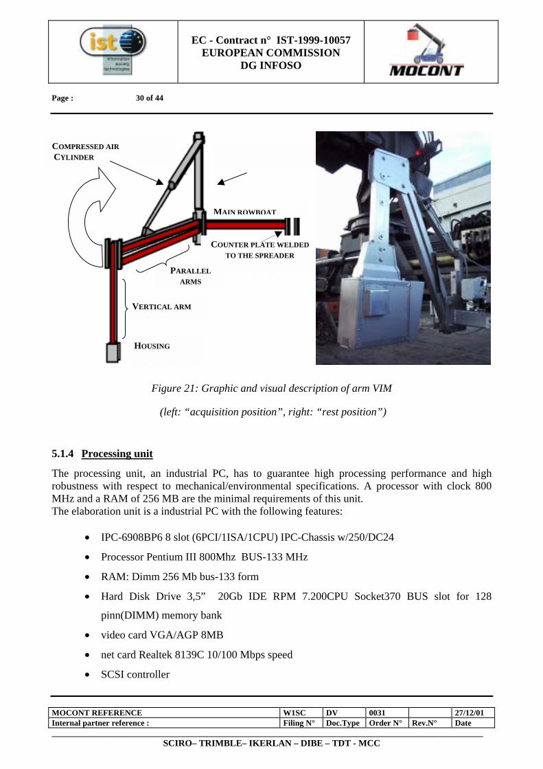
Figure 21: Graphic and visual description of arm VIM
(left: “acquisition position”, right: “rest position”)
5.1.4 Processing unit
The processing unit, an industrial PC, has to guarantee high processing performance and high robustness with respect to mechanical/environmental specifications. A processor with clock 800 MHz and a RAM of 256 MB are the minimal requirements of this unit. The elaboration unit is a industrial PC with the following features:
• IPC-6908BP6 8 slot (6PCI/1ISA/1CPU) IPC-Chassis w/250/DC24
• Processor Pentium III 800Mhz BUS-133 MHz
• RAM: Dimm 256 Mb bus-133 form
• Hard Disk Drive 3,5” 20Gb IDE RPM 7.200CPU Socket370 BUS slot for 128
pinn(DIMM) memory bank
• video card VGA/AGP 8MB
• net card Realtek 8139C 10/100 Mbps speed
• SCSI controller
MAIN ROWBOAT
COMPRESSED AIR CYLINDER
VERTICAL ARM
COUNTER PLATE WELDED TO THE SPREADER
HOUSING
PARALLEL ARMS
EC - Contract n° IST-1999-10057
EUROPEAN COMMISSION DG INFOSO
Page : 31 of 44
MOCONT REFERENCE W1SC DV 0031 27/12/01 Internal partner reference : Filing N° Doc.Type Order N° Rev.N° Date _________________________________________________________________________________________________________
SCIRO– TRIMBLE– IKERLAN – DIBE – TDT - MCC
• PCI DMA/33 o DMA/66 MB/sec BUS
• two serials, a parallel, USB and two PS2 used for keyboard and mouse.
The processing unit is enhanced with a video signal acquisition card. The objective of the frame grabber is to read the camera signal and allocate the image information in the system (host CPU) memory. The frame grabber installed on the processing unit is a video board Matrox Meteor II.
6 VISUAL IDENTIFICATION MODULE FUNCTIONS
In this chapter the principal functions of the visual identification module are presented. The VIM functions are grouped in five different categories:
• Switching on • Camera positioning • Acquisition • Data processing • Data output
6.1 SWITCHING ON
The VIM has an automatically start-up system. When the operator turns the key on the reach stacker panel, all the components are supplied: the camera, all the Detector Equipment Housing components and the arm movement system are under tension. The operating system is loaded and, then, acquisition and communication software are executed automatically. Shortly afterwards the reach stacker starts-up, the VIM is in READY STATE
6.2 CAMERA POSITIONING
The operator starts his work on the terminal yard. To handle a container, the spreader twist locks have to be inserted on the four holes located on the container top, named corner castings. The strain-gage sensors mounted on the spreaders check the correct insertion of the twist lock inside the corner castings. The main phases of this operation are highlighted to the operator by means of a light signal mechanism. When the twist locks are connected, on the control panel a yellow light switch on; when the twist locks are locked a green light switch on, otherwise the red light is switched on. The green light signal works as trigger command that starts the arm descent until the acquisition position is reached. The camera is positioned in front of the ROI centre (Region Of Interest). The green light acts as the consent to camera positioning.
6.3 ACQUISITION
A magnetic reed sensor located on the cylinder, used to control all the arm movements, provides an electrical signal when the arm is in acquisition position. The electrical signal coming from the
EC - Contract n° IST-1999-10057
EUROPEAN COMMISSION DG INFOSO
Page : 32 of 44
MOCONT REFERENCE W1SC DV 0031 27/12/01 Internal partner reference : Filing N° Doc.Type Order N° Rev.N° Date _________________________________________________________________________________________________________
SCIRO– TRIMBLE– IKERLAN – DIBE – TDT - MCC
magnetic reed sensor triggers the VIM recognition process. The camera starts to acquire at 25 frames /sec, and after one second the moving up arm command is sent. The camera stops acquisition process and the arm moves towards its rest position. The acquired frames that are coming from the camera are coded using the CCIR format (analog signal) and transmitted to the elaboration unit by means of an opportune coaxial cable (high flexibility and robustness to noise ). The whole frame sequence is digitalized and stored by the frame grabber to allow the following processing. The frame grabber stores and makes a digital conversion of the frame sequence and the data processing start. These steps are computed consecutively and independently to the arm movements operations.
6.4 DATA PROCESSING
The VIM software module performs the recognition process starting from the acquisition task, till the recognition of the single characters composing the container identification code. Between these two tasks exist many important processes that realize intermediate functions as, for example, the image calibration or the image segmentation. All these sub-modules are described in the following sections after a detailed representation of all relations and data flows existing between sub-modules.
6.4.1 Software module overall description
The software module performs two functions that are the management of input (directly from user or from other systems as SCM) and the recognition process. If user interacts with the system he can select the type of source. The user can load an image stored in the PC or he can acquire a new image using the camera (see Figure 19). In the opposite case, when the VIM system interacts with SCM and SSS, the flow of events as acquisition, segmentation or recognition are controlled by a fix state diagram. The overall process starts with the acquisition of the container right part, where container identification code is depicted. The acquisition sub-module, in charge of controlling the camera and managing its output (video standard CCIR), receives a frame flow at the rate of 25 frame/sec and stores a sequence of 1 sec. Because of the camera position, the acquired frames are rotated of 90° counter-clockwise. The second sub-module (pre-processing) analyzes the frame sequence and, on the base of statistic measurements, selects the best frame that is the frame with the less noise. Two transformation are then applied to the selected frame: rotation of 90° clockwise and recovering distortion (this last function is performed by the calibration sub-module). The frame (here after also named image) is processed to localize the character composing the identification code(Segmentation sub-module) this analysis terminates with a number of “regions” here after also called ROC (Region Of Character). Almost all the ROC contain characters and only a minor part corresponds to false alarms. The region selection sub-module is in charge of reducing the number of false alarm often easy to notice because of the shape or the topological distribution. After this kind of filtering the new list of ROC is sorted (sorting sub-module) with the normal image - raster criteria (by rows). This sorted list is processed to create a characters layout that can be vertical or horizontal, single row/column or double or triple etc. This final step corresponds to the end of the code localization
EC - Contract n° IST-1999-10057
EUROPEAN COMMISSION DG INFOSO
Page : 33 of 44
MOCONT REFERENCE W1SC DV 0031 27/12/01 Internal partner reference : Filing N° Doc.Type Order N° Rev.N° Date _________________________________________________________________________________________________________
SCIRO– TRIMBLE– IKERLAN – DIBE – TDT - MCC
process that, acting as an image compressor, discards from the original image each not useful information while extracts each character presents on the scene. The layout information is the code recognition process input. This second processing recognizes each single character and selects the eleven elements of the identification code from among all the recognized string.
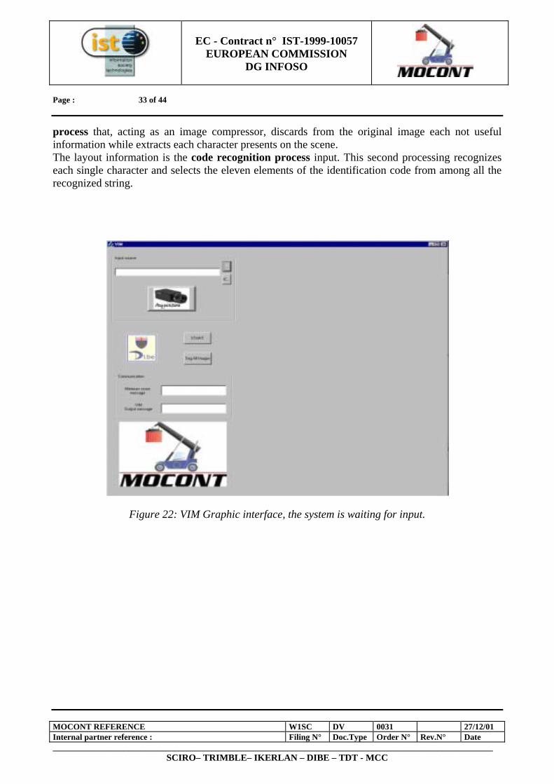
Figure 22: VIM Graphic interface, the system is waiting for input.
EC - Contract n° IST-1999-10057
EUROPEAN COMMISSION DG INFOSO
Page : 34 of 44
MOCONT REFERENCE W1SC DV 0031 27/12/01 Internal partner reference : Filing N° Doc.Type Order N° Rev.N° Date _________________________________________________________________________________________________________
SCIRO– TRIMBLE– IKERLAN – DIBE – TDT - MCC
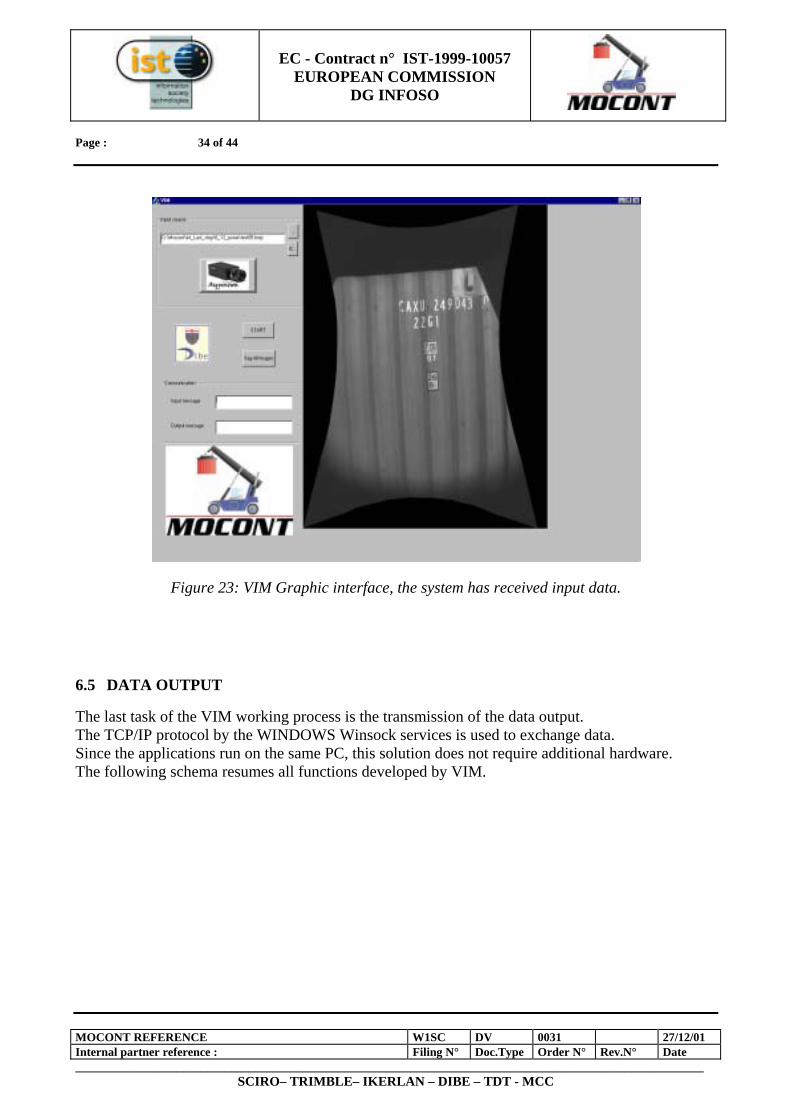
Figure 23: VIM Graphic interface, the system has received input data.
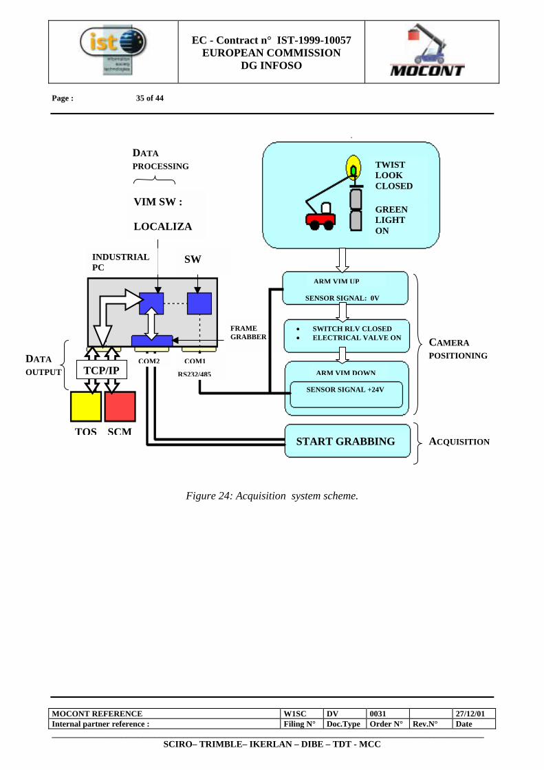
6.5 DATA OUTPUT
The last task of the VIM working process is the transmission of the data output. The TCP/IP protocol by the WINDOWS Winsock services is used to exchange data. Since the applications run on the same PC, this solution does not require additional hardware. The following schema resumes all functions developed by VIM.
EC - Contract n° IST-1999-10057
EUROPEAN COMMISSION DG INFOSO
Page : 35 of 44
MOCONT REFERENCE W1SC DV 0031 27/12/01 Internal partner reference : Filing N° Doc.Type Order N° Rev.N° Date _________________________________________________________________________________________________________
SCIRO– TRIMBLE– IKERLAN – DIBE – TDT - MCC
Figure 24: Acquisition system scheme.
TWIST LOOK CLOSED
GREEN LIGHT ON
• SWITCH RLV CLOSED • ELECTRICAL VALVE ON
INDUSTRIAL PC
SW
VIM SW :
LOCALIZA
FRAME GRABBER
RS232/485
START GRABBING
COM1COM2ARM VIM DOWN
SENSOR SIGNAL +24V
ARM VIM UP
SENSOR SIGNAL: 0V
TOS SCM
TCP/IP
CAMERA POSITIONING
ACQUISITION
DATA OUTPUT
DATA PROCESSING
EC - Contract n° IST-1999-10057
EUROPEAN COMMISSION DG INFOSO
Page : 36 of 44
MOCONT REFERENCE W1SC DV 0031 27/12/01 Internal partner reference : Filing N° Doc.Type Order N° Rev.N° Date _________________________________________________________________________________________________________
SCIRO– TRIMBLE– IKERLAN – DIBE – TDT - MCC
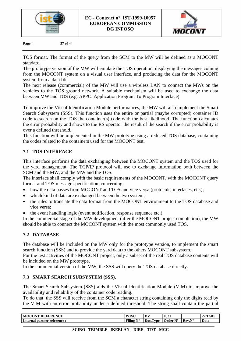
7 INTERFACE WITH THE TOS
The MOCONT system interacts with the TOS through the layer named Middle Ware (MW). The MW is the interface between MOCONT and the TOS which performs the following tasks: 1. the MW translates the information coming from the MOCONT system to the TOS data format,
when information is sent from MOCONT to the TOS. The software interface MIT (Middle ware Interface to TOS) will realise this task;
2. the MW handle the communication layer between the MOCONT vehicle equipment and the TOS (usually located at the ground terminal station);
3. the MW translates the information coming from the TOS and sends it to the right MOCONT subsystem through the Synchronisation subsystem (SCM). The software interface MIM (Middle ware interface to MOCONT) will realise this task;
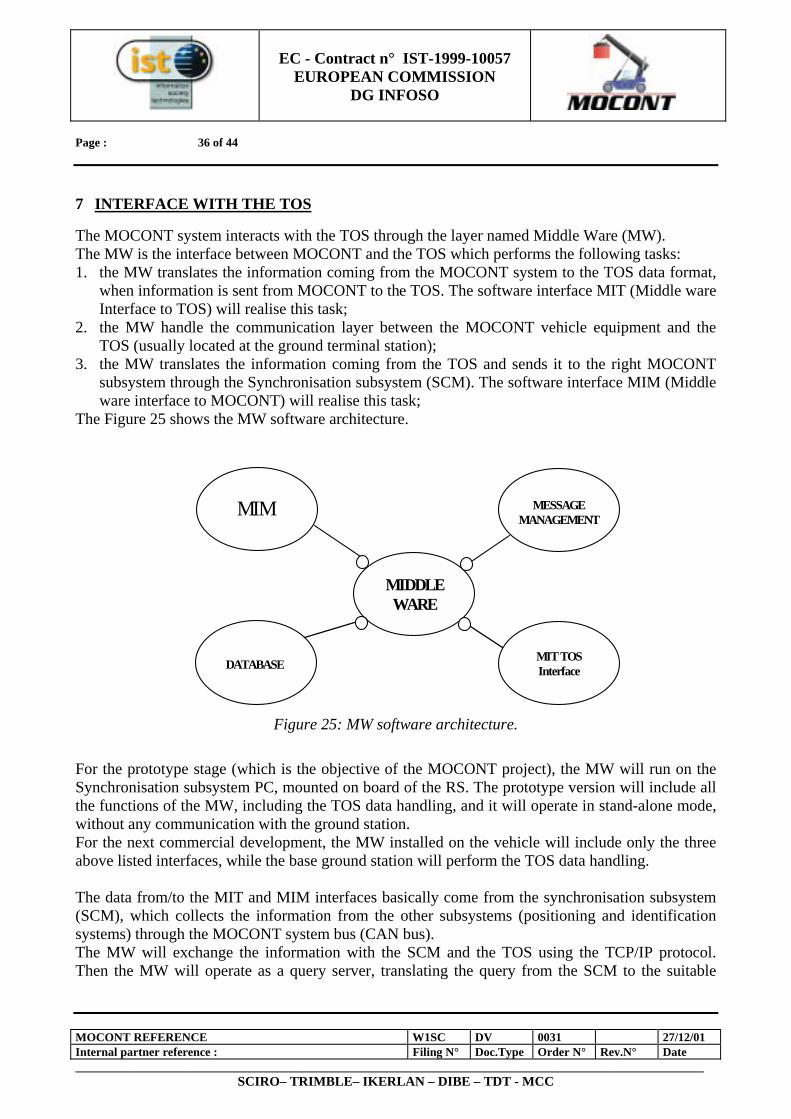
The Figure 25 shows the MW software architecture.
Figure 25: MW software architecture.
For the prototype stage (which is the objective of the MOCONT project), the MW will run on the Synchronisation subsystem PC, mounted on board of the RS. The prototype version will include all the functions of the MW, including the TOS data handling, and it will operate in stand-alone mode, without any communication with the ground station. For the next commercial development, the MW installed on the vehicle will include only the three above listed interfaces, while the base ground station will perform the TOS data handling. The data from/to the MIT and MIM interfaces basically come from the synchronisation subsystem (SCM), which collects the information from the other subsystems (positioning and identification systems) through the MOCONT system bus (CAN bus). The MW will exchange the information with the SCM and the TOS using the TCP/IP protocol. Then the MW will operate as a query server, translating the query from the SCM to the suitable
MESSAGE
MANAGEMENTMIM
DATABASE MIT TOS Interface
MIDDLE WARE
EC - Contract n° IST-1999-10057
EUROPEAN COMMISSION DG INFOSO
Page : 37 of 44
MOCONT REFERENCE W1SC DV 0031 27/12/01 Internal partner reference : Filing N° Doc.Type Order N° Rev.N° Date _________________________________________________________________________________________________________
SCIRO– TRIMBLE– IKERLAN – DIBE – TDT - MCC
TOS format. The format of the query from the SCM to the MW will be defined as a MOCONT standard. The prototype version of the MW will emulate the TOS operation, displaying the messages coming from the MOCONT system on a visual user interface, and producing the data for the MOCONT system from a data file. The next release (commercial) of the MW will use a wireless LAN to connect the MWs on the vehicles to the TOS ground network. A suitable mechanism will be used to exchange the data between MW and TOS (e.g. APPC: Application Program To Program Interface). To improve the Visual Identification Module performances, the MW will also implement the Smart Search Subsystem (SSS). This function uses the entire or partial (maybe corrupted) container ID code to search on the TOS the container(s) code with the best likelihood. The function calculates the error probability and shows to the RS operator the result of the search if the error probability is over a defined threshold. This function will be implemented in the MW prototype using a reduced TOS database, containing the codes related to the containers used for the MOCONT test.
7.1 TOS INTERFACE
This interface performs the data exchanging between the MOCONT system and the TOS used for the yard management. The TCP/IP protocol will use to exchange information both between the SCM and the MW, and the MW and the TOS. The interface shall comply with the basic requirements of the MOCONT, with the MOCONT query format and TOS message specification, concerning: • how the data passes from MOCONT and TOS and vice versa (protocols, interfaces, etc.); • which kind of data are exchanged between the two system; • the rules to translate the data format from the MOCONT environment to the TOS database and
vice versa; • the event handling logic (event notification, response sequence etc.). In the commercial stage of the MW development (after the MOCONT project completion), the MW should be able to connect the MOCONT system with the most commonly used TOS.
7.2 DATABASE
The database will be included on the MW only for the prototype version, to implement the smart search function (SSS) and to provide the yard data to the others MOCONT subsystem. For the test activities of the MOCONT project, only a subset of the real TOS database contents will be included on the MW prototype. In the commercial version of the MW, the SSS will query the TOS database directly.
7.3 SMART SEARCH SUBSYSTEM (SSS).
The Smart Search Subsystem (SSS) aids the Visual Identification Module (VIM) to improve the availability and reliability of the container code reading. To do that, the SSS will receive from the SCM a character string containing only the digits read by the VIM with an error probability under a defined threshold. The string shall contain the partial
EC - Contract n° IST-1999-10057
EUROPEAN COMMISSION DG INFOSO
Page : 38 of 44
MOCONT REFERENCE W1SC DV 0031 27/12/01 Internal partner reference : Filing N° Doc.Type Order N° Rev.N° Date _________________________________________________________________________________________________________
SCIRO– TRIMBLE– IKERLAN – DIBE – TDT - MCC
container code digits in the same sequence as they appear in the complete code. The SSS will operate only if a minimum number of container code digits is available, otherwise the VIM will produce an error and the SCM will ask the operator for the right container code (so that the error will be recovered). Then the SSS will search on the TOS database all the container with the code compatible with partial string received from the VIM. The SSS will calculate a likelihood score, in the range 0..100%, which defines the compliance degree of any container code found in the TOS with the string from the VIM. If the likelihood score is over a defined threshold for at least one container, the SSS will decide that the one with the best score is the container handled by the RS. If the retrieval result consists of two or more container code with best likelihood score, and it’s available further processing time , the SCM sends this list to VIM. Using fast matching techniques the VIM will be able to provide the final identification code as soon as “the stop identify” message is received. In all other cases, the SCM will display the container list issued by the SSS to the operator and the operator will choose the right container or he will provide the right code using the SCM user interface.
7.4 MESSAGE MANAGEMENT
Some message, concerning both the MOCONT operation and the TOS communications to the RS operator, should be displayed on the user visual interface. Then the MW messages (coming from the TOS or generated by the MW logic) will be sent to the synchronisation module (SCM) which will display them on the user panel. The MW shall supply the messages in the proper format and language.
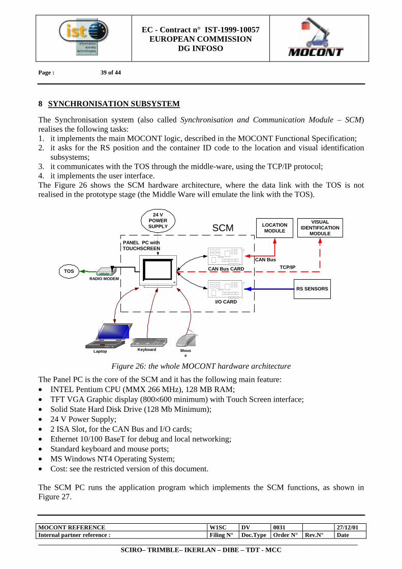
EC - Contract n° IST-1999-10057
EUROPEAN COMMISSION DG INFOSO
Page : 39 of 44
MOCONT REFERENCE W1SC DV 0031 27/12/01 Internal partner reference : Filing N° Doc.Type Order N° Rev.N° Date _________________________________________________________________________________________________________
SCIRO– TRIMBLE– IKERLAN – DIBE – TDT - MCC
8 SYNCHRONISATION SUBSYSTEM
The Synchronisation system (also called Synchronisation and Communication Module – SCM) realises the following tasks: 1. it implements the main MOCONT logic, described in the MOCONT Functional Specification; 2. it asks for the RS position and the container ID code to the location and visual identification
subsystems; 3. it communicates with the TOS through the middle-ware, using the TCP/IP protocol; 4. it implements the user interface. The Figure 26 shows the SCM hardware architecture, where the data link with the TOS is not realised in the prototype stage (the Middle Ware will emulate the link with the TOS).
PANEL PC withTOUCHSCREEN
CAN Bus CARD
I/O CARD
LOCATIONMODULE
VISUALIDENTIFICATION
MODULE
CAN Bus
RS SENSORS
24 VPOWERSUPPLY
RADIO MODEM
TOS
Laptop Keyboard Mouse
SCM
TCP/IP
Figure 26: the whole MOCONT hardware architecture
The Panel PC is the core of the SCM and it has the following main feature: • INTEL Pentium CPU (MMX 266 MHz), 128 MB RAM; • TFT VGA Graphic display (800×600 minimum) with Touch Screen interface; • Solid State Hard Disk Drive (128 Mb Minimum); • 24 V Power Supply; • 2 ISA Slot, for the CAN Bus and I/O cards; • Ethernet 10/100 BaseT for debug and local networking; • Standard keyboard and mouse ports; • MS Windows NT4 Operating System; • Cost: see the restricted version of this document. The SCM PC runs the application program which implements the SCM functions, as shown in Figure 27.
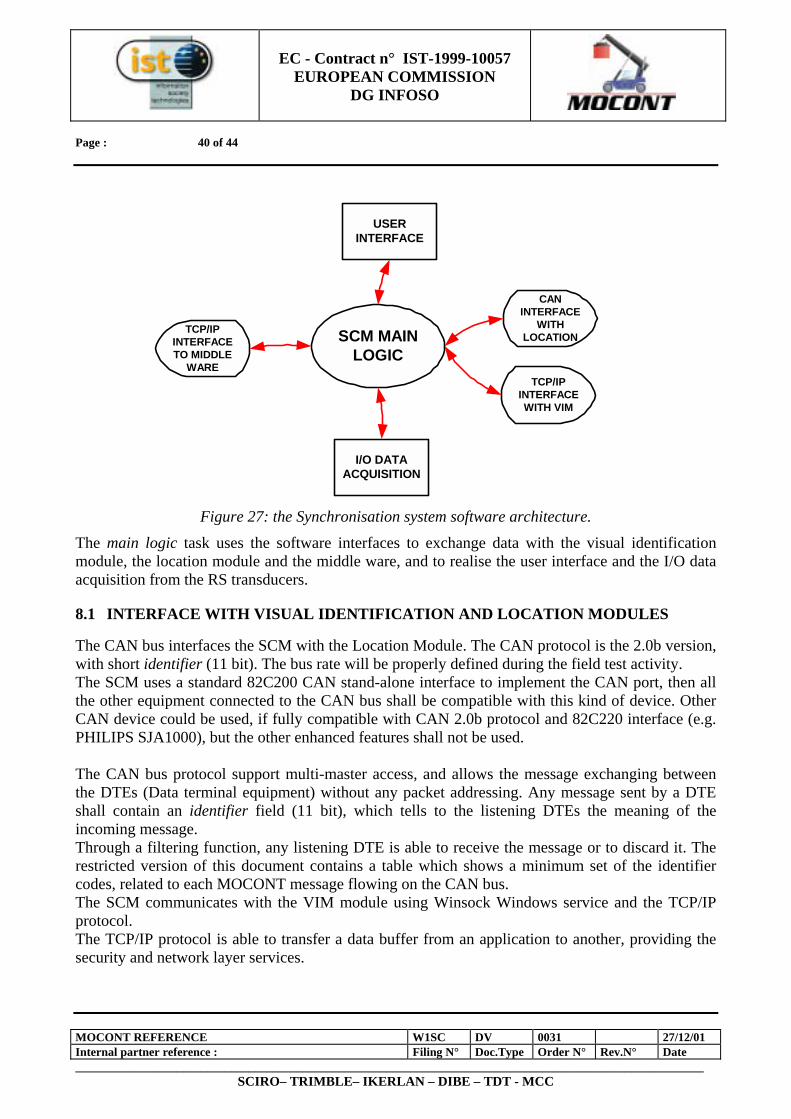
EC - Contract n° IST-1999-10057
EUROPEAN COMMISSION DG INFOSO
Page : 40 of 44
MOCONT REFERENCE W1SC DV 0031 27/12/01 Internal partner reference : Filing N° Doc.Type Order N° Rev.N° Date _________________________________________________________________________________________________________
SCIRO– TRIMBLE– IKERLAN – DIBE – TDT - MCC
Figure 27: the Synchronisation system software architecture.
The main logic task uses the software interfaces to exchange data with the visual identification module, the location module and the middle ware, and to realise the user interface and the I/O data acquisition from the RS transducers.
8.1 INTERFACE WITH VISUAL IDENTIFICATION AND LOCATION MODULES
The CAN bus interfaces the SCM with the Location Module. The CAN protocol is the 2.0b version, with short identifier (11 bit). The bus rate will be properly defined during the field test activity. The SCM uses a standard 82C200 CAN stand-alone interface to implement the CAN port, then all the other equipment connected to the CAN bus shall be compatible with this kind of device. Other CAN device could be used, if fully compatible with CAN 2.0b protocol and 82C220 interface (e.g. PHILIPS SJA1000), but the other enhanced features shall not be used. The CAN bus protocol support multi-master access, and allows the message exchanging between the DTEs (Data terminal equipment) without any packet addressing. Any message sent by a DTE shall contain an identifier field (11 bit), which tells to the listening DTEs the meaning of the incoming message. Through a filtering function, any listening DTE is able to receive the message or to discard it. The restricted version of this document contains a table which shows a minimum set of the identifier codes, related to each MOCONT message flowing on the CAN bus. The SCM communicates with the VIM module using Winsock Windows service and the TCP/IP protocol. The TCP/IP protocol is able to transfer a data buffer from an application to another, providing the security and network layer services.
SCM MAINLOGIC
TCP/IPINTERFACETO MIDDLE
WARE
CANINTERFACE
WITHLOCATION
TCP/IPINTERFACEWITH VIM
USERINTERFACE
I/O DATAACQUISITION
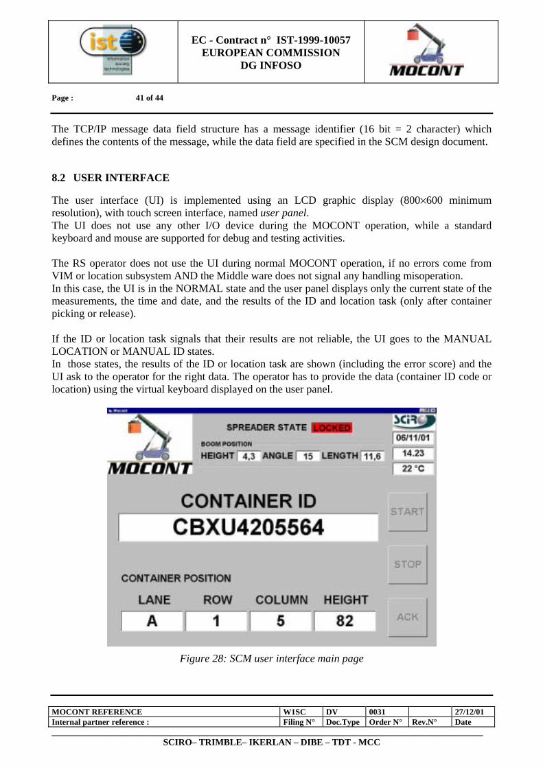
EC - Contract n° IST-1999-10057
EUROPEAN COMMISSION DG INFOSO
Page : 41 of 44
MOCONT REFERENCE W1SC DV 0031 27/12/01 Internal partner reference : Filing N° Doc.Type Order N° Rev.N° Date _________________________________________________________________________________________________________
SCIRO– TRIMBLE– IKERLAN – DIBE – TDT - MCC
The TCP/IP message data field structure has a message identifier (16 bit = 2 character) which defines the contents of the message, while the data field are specified in the SCM design document.
8.2 USER INTERFACE
The user interface (UI) is implemented using an LCD graphic display (800×600 minimum resolution), with touch screen interface, named user panel. The UI does not use any other I/O device during the MOCONT operation, while a standard keyboard and mouse are supported for debug and testing activities. The RS operator does not use the UI during normal MOCONT operation, if no errors come from VIM or location subsystem AND the Middle ware does not signal any handling misoperation. In this case, the UI is in the NORMAL state and the user panel displays only the current state of the measurements, the time and date, and the results of the ID and location task (only after container picking or release). If the ID or location task signals that their results are not reliable, the UI goes to the MANUAL LOCATION or MANUAL ID states. In those states, the results of the ID or location task are shown (including the error score) and the UI ask to the operator for the right data. The operator has to provide the data (container ID code or location) using the virtual keyboard displayed on the user panel.
Figure 28: SCM user interface main page
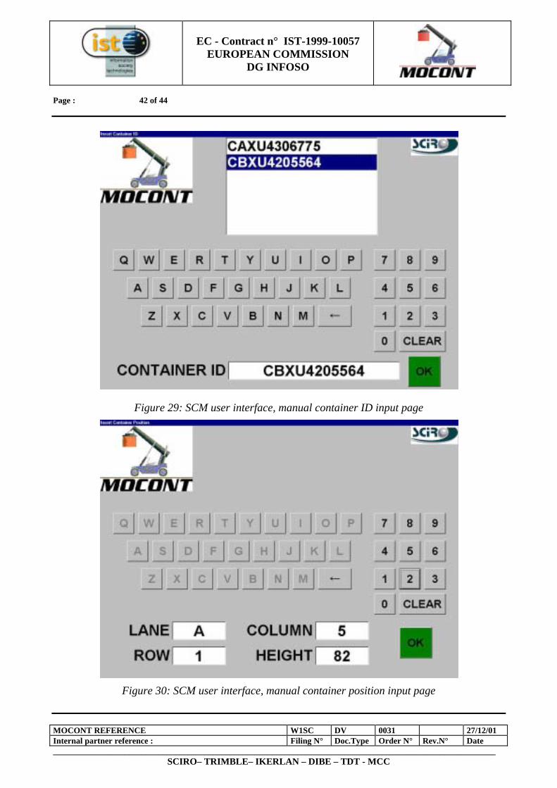
EC - Contract n° IST-1999-10057
EUROPEAN COMMISSION DG INFOSO
Page : 42 of 44
MOCONT REFERENCE W1SC DV 0031 27/12/01 Internal partner reference : Filing N° Doc.Type Order N° Rev.N° Date _________________________________________________________________________________________________________
SCIRO– TRIMBLE– IKERLAN – DIBE – TDT - MCC
Figure 29: SCM user interface, manual container ID input page
Figure 30: SCM user interface, manual container position input page
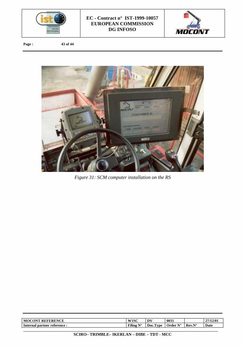
EC - Contract n° IST-1999-10057
EUROPEAN COMMISSION DG INFOSO
Page : 43 of 44
MOCONT REFERENCE W1SC DV 0031 27/12/01 Internal partner reference : Filing N° Doc.Type Order N° Rev.N° Date _________________________________________________________________________________________________________
SCIRO– TRIMBLE– IKERLAN – DIBE – TDT - MCC
Figure 31: SCM computer installation on the RS

EC - Contract n° IST-1999-10057
EUROPEAN COMMISSION DG INFOSO
Page : 44 of 44
MOCONT REFERENCE W1SC DV 0031 27/12/01 Internal partner reference : Filing N° Doc.Type Order N° Rev.N° Date _________________________________________________________________________________________________________
SCIRO– TRIMBLE– IKERLAN – DIBE – TDT - MCC
9 CONCLUSIONS
The objectives which had been fixed at the very beginning of MOCONT Research Project, summarised in Chapter 2: Overview of the objectives of MOCONT research project, have been successfully achieved at the end of the two-years work, as shown by the description of the first MOCONT working prototype in Chapters 3 to 8. The project satisfactory results have also produced, in the last weeks of the project life time, a further interest from the European Commission who decided to co-finance a take up measure, acronym MOCONT-II, in order to equip a fleet of reach stackers with 8 MOCONT “boxes”,and test their behaviour during six months of normal operation.