Embed Size (px)
Citation preview

FLEXI-COIL Series 67 Installation Manual
Spray Height Control System
Improving the competitiveness of Industry and Agriculture through Precision Measurement
Printed in Canada Copyright 2005-08 by NORAC Systems International Inc.
Reorder P/N: UC4+BC+FC1-INST REV F (FLEXI-COIL Series 67)
NORAC Systems International Inc. reserves the right to improve products and their specifications without notice and without the requirement to update products sold previously. Every effort has been made to ensure the accuracy of the information contained in this manual. The technical information in this manual was reviewed at the time of approval for publication.
TABLE OF CONTENTS
1 INTRODUCTION ................................................................................................................................. 1
2 GENERAL SYSTEM DESCRIPTION .................................................................................................. 2
3 PARTS LISTS ......................................................................................................................................... 3
4 INSTALLATION PROCEDURE .......................................................................................................... 7
4.1 EXISTING SYSTEM CHECK ................................................................................................................. 7 4.2 BOOM SPEED TEST ........................................................................................................................... 7 4.3 WING SENSOR INSTALLATION ......................................................................................................... 9 4.4 MAIN LIFT SENSOR INSTALLATION ................................................................................................ 12 4.5 ROLL SENSOR INSTALLATION ........................................................................................................ 13
4.5.1 Boom Roll Sensor Mounting ................................................................................................................................................ 14 4.5.2 Chassis Roll Sensor Mounting ............................................................................................................................................. 14 4.5.3 Inverted Roll Sensor Mounting ............................................................................................................................................ 16 4.5.4 Temperature probe ................................................................................................................................................................ 16
4.6 HYDRAULIC INSTALLATION ........................................................................................................... 17 4.6.1 Valve Assembly ........................................................................................................................................................................ 17 4.6.2 Valve Mounting ....................................................................................................................................................................... 18 4.6.3 Hydraulic Plumbing ................................................................................................................................................................ 19
4.7 ELECTRICAL INSTALLATION ........................................................................................................... 20 4.8 COMPLETING THE INSTALLATION .................................................................................................. 23
5 ELECTRICAL REFERENCE – CABLE DRAWINGS ....................................................................... 24
5.1 ITEM C01: 44662B-40 – SENSOR TRUNK CABLE ........................................................................... 24 5.2 ITEM C06: 44687 – SENSOR EXTENSION CABLE ............................................................................ 27 5.3 ITEM C02: 44668 – SENSOR BRANCH CABLE ................................................................................. 24 5.4 ITEM C02B: 44664 – CABLE UC4 CAN NODE DUAL ................................................................... 25 5.5 ITEM C03: 44656D – CABLE VALVE VARIABLE RATE DT .............................................................. 26 5.6 ITEM C04: 44651 – VALVE EXTENSION CABLE .............................................................................. 27 5.7 ITEM C10: 44650-09 – POWER CABLE FOR FLEXI-COIL 67 SERIES ............................................ 28
1
1 INTRODUCTION
Congratulations on your purchase of the NORAC UC4+ Spray Height Control System. This system is manufactured with top quality components and is engineered using the latest technology to provide operating features and reliability unmatched for years to come.
When properly used the system can provide protection from sprayer boom damage, improve sprayer efficiency, and ensure chemicals are applied correctly.
Please take the time to read this manual completely before attempting to install the system. A thorough understanding of this manual will ensure that you receive the maximum benefit from the system.
YOUR INPUT CAN HELP MAKE US BETTER! If you find issues or have suggestions regarding the parts list or the installation procedure, please don’t hesitate to contact us.
2
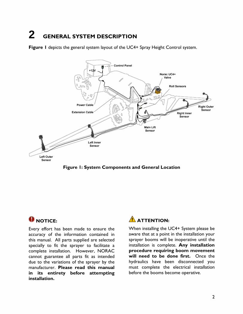
2 GENERAL SYSTEM DESCRIPTION
Figure 1 depicts the general system layout of the UC4+ Spray Height Control system.
Figure 1: System Components and General Location
NOTICE:
Every effort has been made to ensure the accuracy of the information contained in this manual. All parts supplied are selected specially to fit the sprayer to facilitate a complete installation. However, NORAC cannot guarantee all parts fit as intended due to the variations of the sprayer by the manufacturer. Please read this manual in its entirety before attempting installation.
ATTENTION:
When installing the UC4+ System please be aware that at a point in the installation your sprayer booms will be inoperative until the installation is complete. Any installation procedure requiring boom movement will need to be done first. Once the hydraulics have been disconnected you must complete the electrical installation before the booms become operative.
3
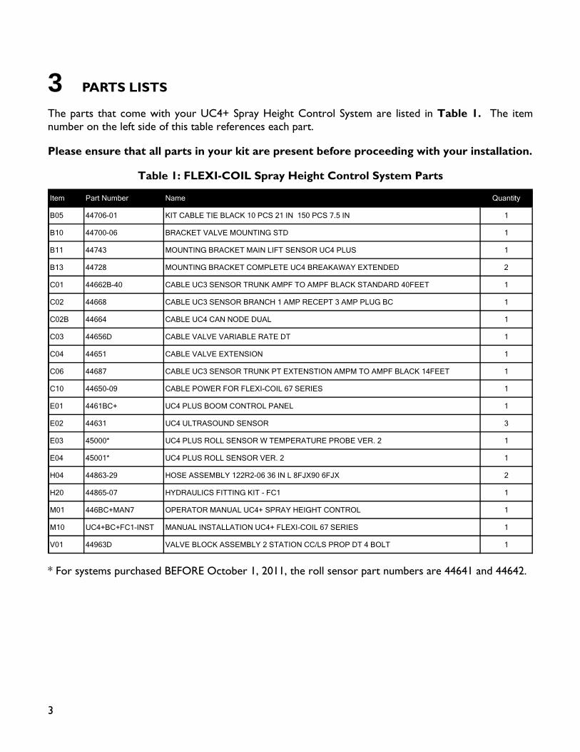
3 PARTS LISTS
The parts that come with your UC4+ Spray Height Control System are listed in Table 1. The item number on the left side of this table references each part.
Please ensure that all parts in your kit are present before proceeding with your installation.
Table 1: FLEXI-COIL Spray Height Control System Parts
Item Part Number Name Quantity
B05 44706-01 KIT CABLE TIE BLACK 10 PCS 21 IN 150 PCS 7.5 IN 1
B10 44700-06 BRACKET VALVE MOUNTING STD 1
B11 44743 MOUNTING BRACKET MAIN LIFT SENSOR UC4 PLUS 1
B13 44728 MOUNTING BRACKET COMPLETE UC4 BREAKAWAY EXTENDED 2
C01 44662B-40 CABLE UC3 SENSOR TRUNK AMPF TO AMPF BLACK STANDARD 40FEET 1
C02 44668 CABLE UC3 SENSOR BRANCH 1 AMP RECEPT 3 AMP PLUG BC 1
C02B 44664 CABLE UC4 CAN NODE DUAL 1
C03 44656D CABLE VALVE VARIABLE RATE DT 1
C04 44651 CABLE VALVE EXTENSION 1
C06 44687 CABLE UC3 SENSOR TRUNK PT EXTENSTION AMPM TO AMPF BLACK 14FEET 1
C10 44650-09 CABLE POWER FOR FLEXI-COIL 67 SERIES 1
E01 4461BC+ UC4 PLUS BOOM CONTROL PANEL 1
E02 44631 UC4 ULTRASOUND SENSOR 3
E03 45000* UC4 PLUS ROLL SENSOR W TEMPERATURE PROBE VER. 2 1
E04 45001* UC4 PLUS ROLL SENSOR VER. 2 1
H04 44863-29 HOSE ASSEMBLY 122R2-06 36 IN L 8FJX90 6FJX 2
H20 44865-07 HYDRAULICS FITTING KIT - FC1 1
M01 446BC+MAN7 OPERATOR MANUAL UC4+ SPRAY HEIGHT CONTROL 1
M10 UC4+BC+FC1-INST MANUAL INSTALLATION UC4+ FLEXI-COIL 67 SERIES 1
V01 44963D VALVE BLOCK ASSEMBLY 2 STATION CC/LS PROP DT 4 BOLT 1
* For systems purchased BEFORE October 1, 2011, the roll sensor part numbers are 44641 and 44642.
4
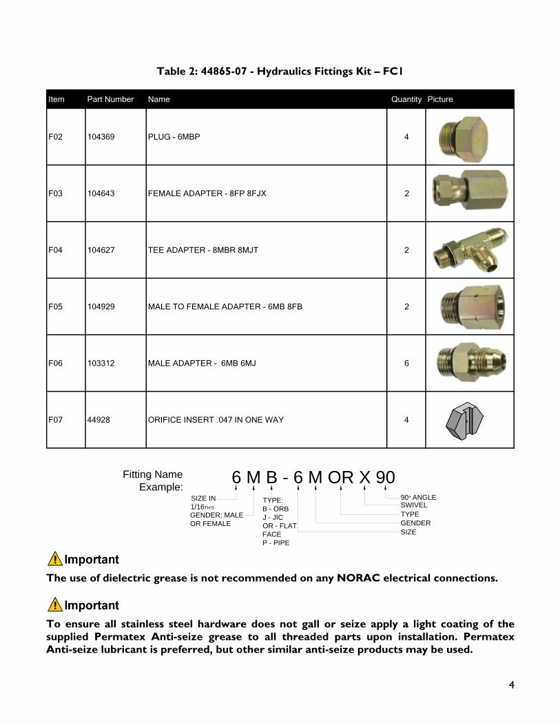
Table 2: 44865-07 - Hydraulics Fittings Kit – FC1
Item Part Number Name Quantity Picture
F02 104369 PLUG - 6MBP 4
F03 104643 FEMALE ADAPTER - 8FP 8FJX 2
F04 104627 TEE ADAPTER - 8MBR 8MJT 2
F05 104929 MALE TO FEMALE ADAPTER - 6MB 8FB 2
F06 103312 MALE ADAPTER - 6MB 6MJ 6
F07 44928 ORIFICE INSERT .047 IN ONE WAY 4
6 M B - 6 M OR X 90SIZE IN 1/16TH'S
GENDER: MALE OR FEMALE
90° ANGLESWIVELTYPEGENDERSIZE
TYPE:B - ORBJ - JICOR - FLAT FACEP - PIPE
Fitting Name Example:
The use of dielectric grease is not recommended on any NORAC electrical connections.
To ensure all stainless steel hardware does not gall or seize apply a light coating of the supplied Permatex Anti-seize grease to all threaded parts upon installation. Permatex Anti-seize lubricant is preferred, but other similar anti-seize products may be used.
5
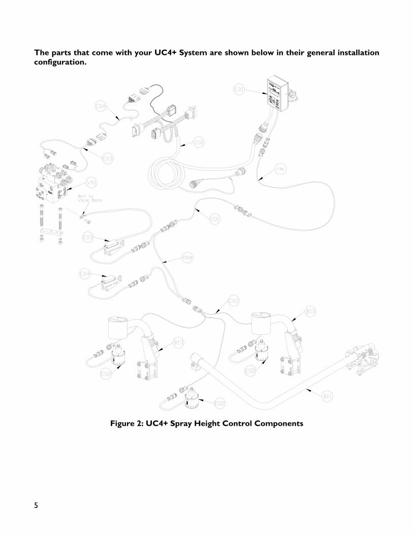
The parts that come with your UC4+ System are shown below in their general installation configuration.
Figure 2: UC4+ Spray Height Control Components
6
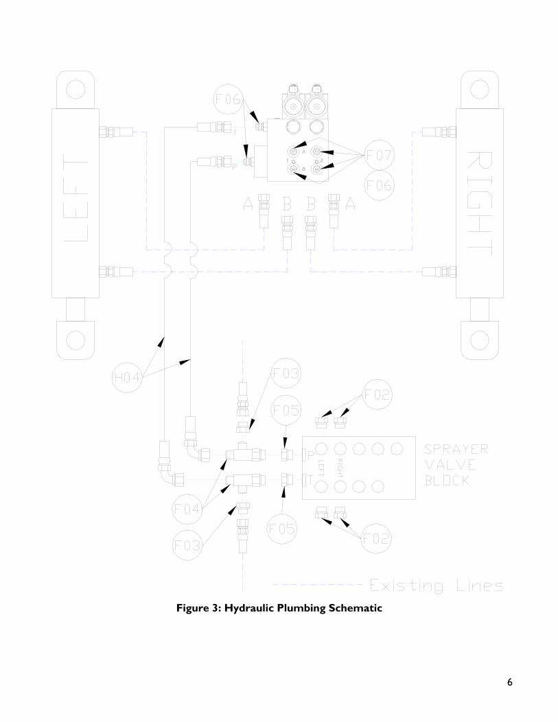
Figure 3: Hydraulic Plumbing Schematic
7
4 INSTALLATION PROCEDURE
4.1 EXISTING SYSTEM CHECK
It is necessary to check the existing system’s functionality before installing the UC4+ system.
1. Drive your sprayer onto a flat piece of land, with unobstructed boom movement (e.g. no power lines).
2. Test that all boom functions operate correctly. As you test each function check it off in Table 3.
It is necessary to test the boom functions in all directions
Table 3: Hydraulic System Function Check Sheet
BOOMFOLD
INFOLD OUT UP DOWN
LEFTMAINRIGHTROLL* N/A N/A
* Some sprayers may not have this function.
4.2 BOOM SPEED TEST
IMPORTANT:
Raise/lower all boom sections several times to warm up the hydraulic system. Grease all moving parts for consistent results.
1. Lower each boom and main section as close to the ground as possible.
2. Set your sprayer at field working RPM on the throttle and mark this value in Table 4.
You will need a stopwatch or a watch that displays “seconds” for the next step.
3. Raise the LEFT boom from its extreme LOW position to the very TOP of its travel. Record the time this takes in Table 4, “Trial #1” for “Left UP”.
4. Lower the LEFT boom from its extreme HIGH position to the BOTTOM of its travel. Record this time in Table 4, Trial #1, for “Left DOWN”.
Be careful when lowering the booms so they don’t hit the ground.
5. Similarly, record two more time trials (Trial #2 & #3) for the LEFT boom and record in Table 4
6. Repeat Steps 1 through 5 for the RIGHT, MAIN and ROLL functions.
Your sprayer may not have a roll feature.
7. Average the three trials recorded for each boom movement and record this calculation in the “Average Time” slot in Table 4.
8. These “Average Times” now represent how quickly your system can react to manual control. In Section 4.8, this procedure is repeated with the UC4+ System installed for comparison and troubleshooting purposes.
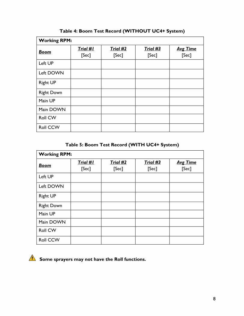
8
Table 4: Boom Test Record (WITHOUT UC4+ System)
Working RPM:
Boom Trial #1
[Sec] Trial #2
[Sec] Trial #3
[Sec] Avg Time
[Sec]
Left UP
Left DOWN
Right UP
Right Down
Main UP
Main DOWN
Roll CW
Roll CCW
Table 5: Boom Test Record (WITH UC4+ System)
Working RPM:
Boom Trial #1
[Sec] Trial #2
[Sec] Trial #3
[Sec] Avg Time
[Sec]
Left UP
Left DOWN
Right UP
Right Down
Main UP
Main DOWN
Roll CW
Roll CCW
Some sprayers may not have the Roll functions.
9
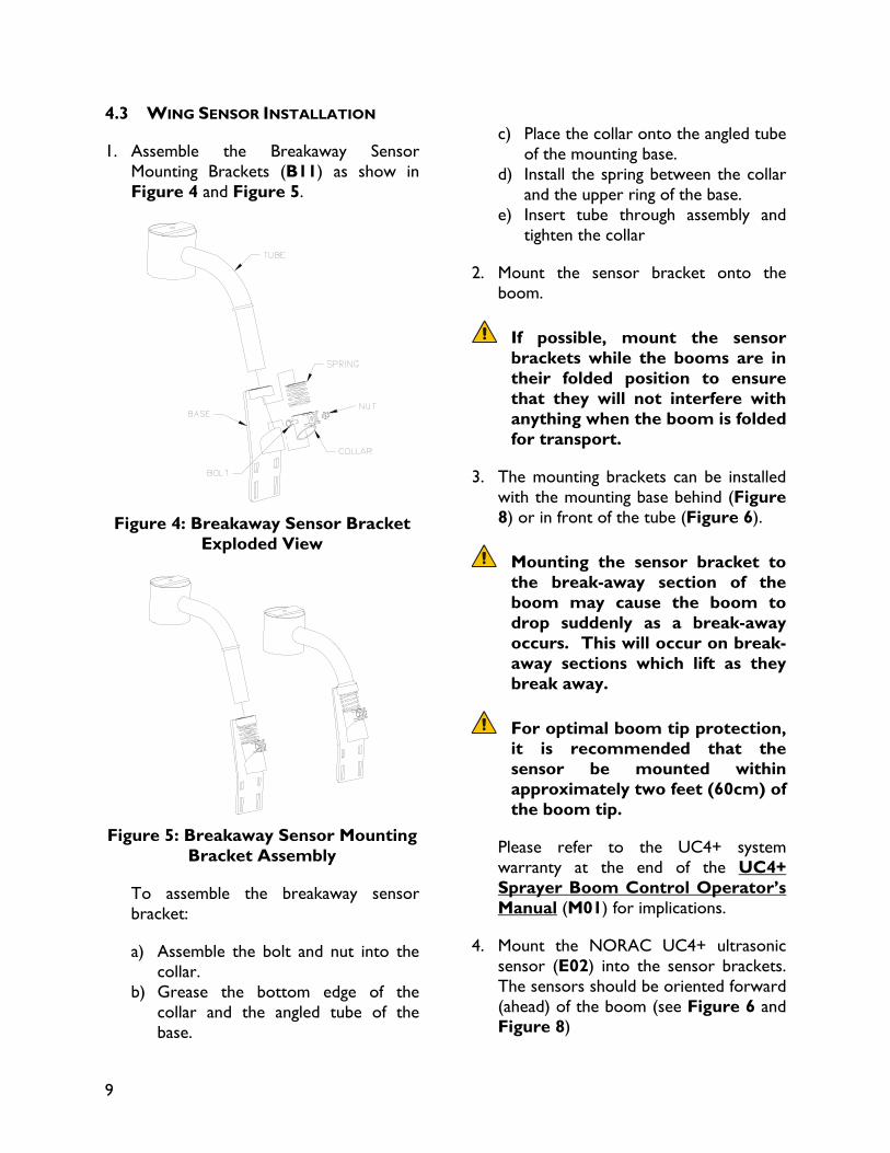
4.3 WING SENSOR INSTALLATION
1. Assemble the Breakaway Sensor Mounting Brackets (B11) as show in Figure 4 and Figure 5.
Figure 4: Breakaway Sensor Bracket
Exploded View
Figure 5: Breakaway Sensor Mounting
Bracket Assembly
To assemble the breakaway sensor bracket:
a) Assemble the bolt and nut into the collar.
b) Grease the bottom edge of the collar and the angled tube of the base.
c) Place the collar onto the angled tube
of the mounting base. d) Install the spring between the collar
and the upper ring of the base. e) Insert tube through assembly and
tighten the collar
2. Mount the sensor bracket onto the boom.
If possible, mount the sensor brackets while the booms are in their folded position to ensure that they will not interfere with anything when the boom is folded for transport.
3. The mounting brackets can be installed with the mounting base behind (Figure 8) or in front of the tube (Figure 6).
Mounting the sensor bracket to the break-away section of the boom may cause the boom to drop suddenly as a break-away occurs. This will occur on break-away sections which lift as they break away.
For optimal boom tip protection, it is recommended that the sensor be mounted within approximately two feet (60cm) of the boom tip.
Please refer to the UC4+ system warranty at the end of the UC4+ Sprayer Boom Control Operator’s Manual (M01) for implications.
4. Mount the NORAC UC4+ ultrasonic sensor (E02) into the sensor brackets. The sensors should be oriented forward (ahead) of the boom (see Figure 6 and Figure 8)
10
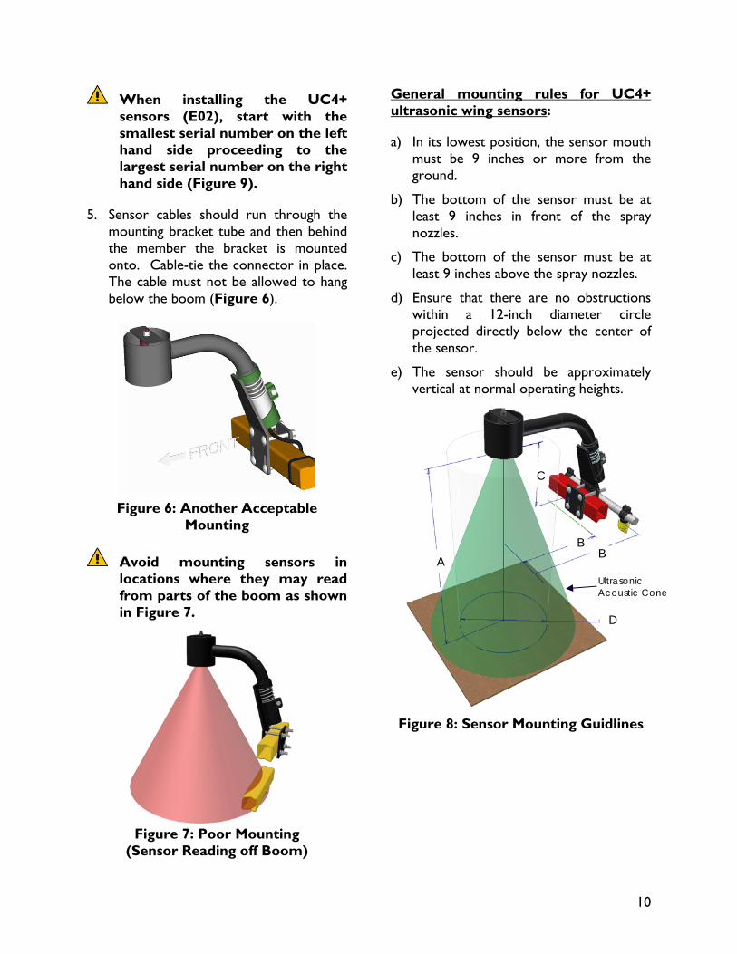
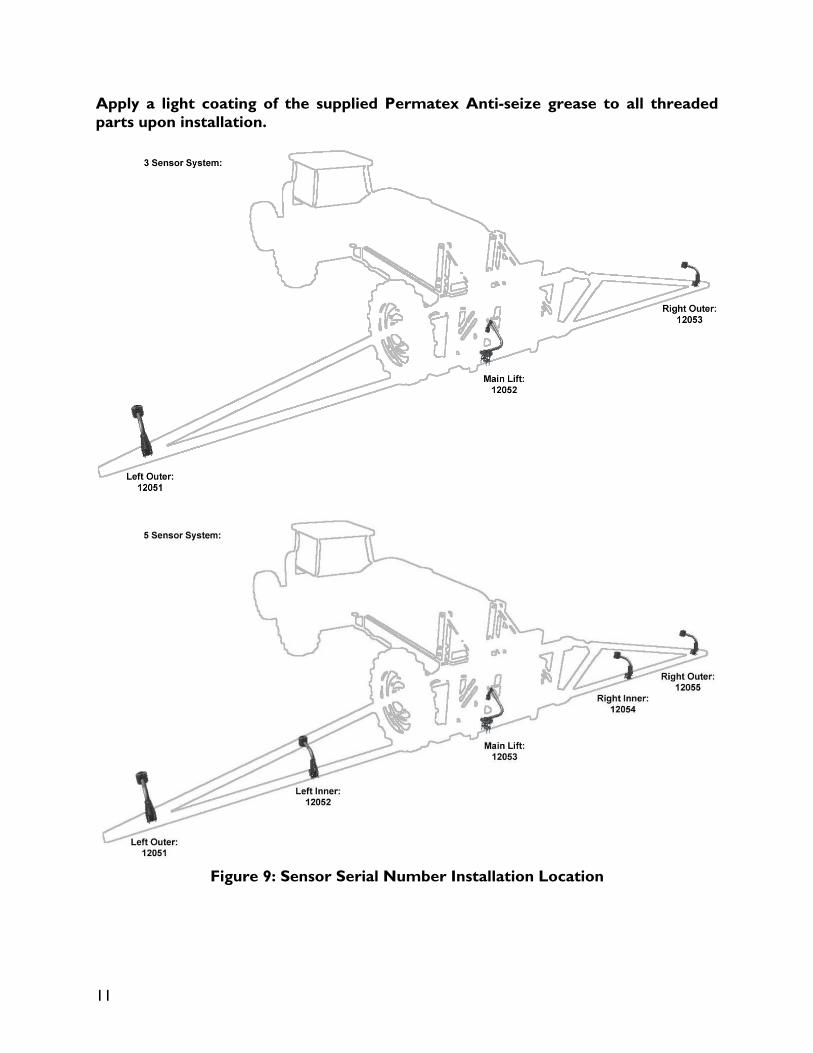
When installing the UC4+ sensors (E02), start with the smallest serial number on the left hand side proceeding to the largest serial number on the right hand side (Figure 9).
5. Sensor cables should run through the mounting bracket tube and then behind the member the bracket is mounted onto. Cable-tie the connector in place. The cable must not be allowed to hang below the boom (Figure 6).
Figure 6: Another Acceptable
Mounting
Avoid mounting sensors in locations where they may read from parts of the boom as shown in Figure 7.
Figure 7: Poor Mounting
(Sensor Reading off Boom)
General mounting rules for UC4+ ultrasonic wing sensors:
a) In its lowest position, the sensor mouth must be 9 inches or more from the ground.
b) The bottom of the sensor must be at least 9 inches in front of the spray nozzles.
c) The bottom of the sensor must be at least 9 inches above the spray nozzles.
d) Ensure that there are no obstructions within a 12-inch diameter circle projected directly below the center of the sensor.
e) The sensor should be approximately vertical at normal operating heights.
Figure 8: Sensor Mounting Guidlines
A B B
D
C
Ultrasonic Acoustic Cone
11
Apply a light coating of the supplied Permatex Anti-seize grease to all threaded parts upon installation.
Figure 9: Sensor Serial Number Installation Location
12
4.4 MAIN LIFT SENSOR INSTALLATION
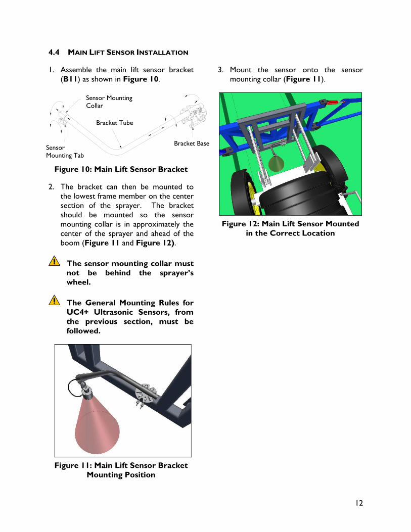
1. Assemble the main lift sensor bracket (B11) as shown in Figure 10.
Figure 10: Main Lift Sensor Bracket
2. The bracket can then be mounted to the lowest frame member on the center section of the sprayer. The bracket should be mounted so the sensor mounting collar is in approximately the center of the sprayer and ahead of the boom (Figure 11 and Figure 12).
The sensor mounting collar must not be behind the sprayer’s wheel.
The General Mounting Rules for UC4+ Ultrasonic Sensors, from the previous section, must be followed.
Figure 11: Main Lift Sensor Bracket
Mounting Position
3. Mount the sensor onto the sensor mounting collar (Figure 11).
Figure 12: Main Lift Sensor Mounted
in the Correct Location
Bracket Tube
Sensor Mounting Tab
Sensor Mounting Collar
Bracket Base
13
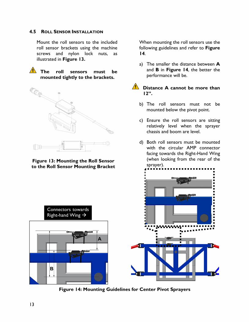
4.5 ROLL SENSOR INSTALLATION
Mount the roll sensors to the included roll sensor brackets using the machine screws and nylon lock nuts, as illustrated in Figure 13.
The roll sensors must be mounted tightly to the brackets.
Figure 13: Mounting the Roll Sensor to the Roll Sensor Mounting Bracket
When mounting the roll sensors use the following guidelines and refer to Figure 14.
a) The smaller the distance between A and B in Figure 14, the better the performance will be.
Distance A cannot be more than 12”.
b) The roll sensors must not be mounted below the pivot point.
c) Ensure the roll sensors are sitting relatively level when the sprayer chassis and boom are level.
d) Both roll sensors must be mounted with the circular AMP connector facing towards the Right-Hand Wing (when looking from the rear of the sprayer).
Figure 14: Mounting Guidelines for Center Pivot Sprayers
Connectors towards Right-hand Wing
14
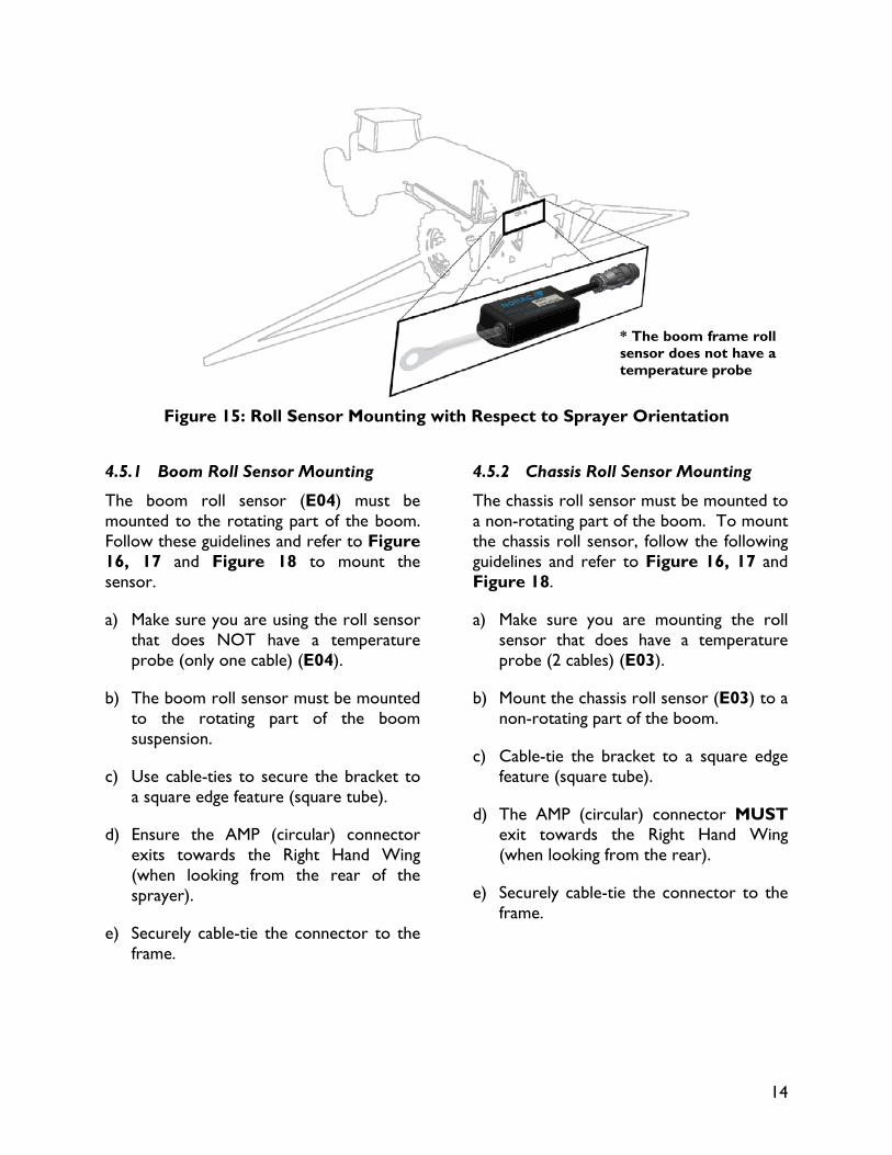
Figure 15: Roll Sensor Mounting with Respect to Sprayer Orientation
4.5.1 Boom Roll Sensor Mounting
The boom roll sensor (E04) must be mounted to the rotating part of the boom. Follow these guidelines and refer to Figure 16, 17 and Figure 18 to mount the sensor.
a) Make sure you are using the roll sensor that does NOT have a temperature probe (only one cable) (E04).
b) The boom roll sensor must be mounted to the rotating part of the boom suspension.
c) Use cable-ties to secure the bracket to a square edge feature (square tube).
d) Ensure the AMP (circular) connector exits towards the Right Hand Wing (when looking from the rear of the sprayer).
e) Securely cable-tie the connector to the frame.
4.5.2 Chassis Roll Sensor Mounting
The chassis roll sensor must be mounted to a non-rotating part of the boom. To mount the chassis roll sensor, follow the following guidelines and refer to Figure 16, 17 and Figure 18.
a) Make sure you are mounting the roll sensor that does have a temperature probe (2 cables) (E03).
b) Mount the chassis roll sensor (E03) to a non-rotating part of the boom.
c) Cable-tie the bracket to a square edge feature (square tube).
d) The AMP (circular) connector MUST exit towards the Right Hand Wing (when looking from the rear).
e) Securely cable-tie the connector to the frame.
* The boom frame roll sensor does not have a temperature probe
15
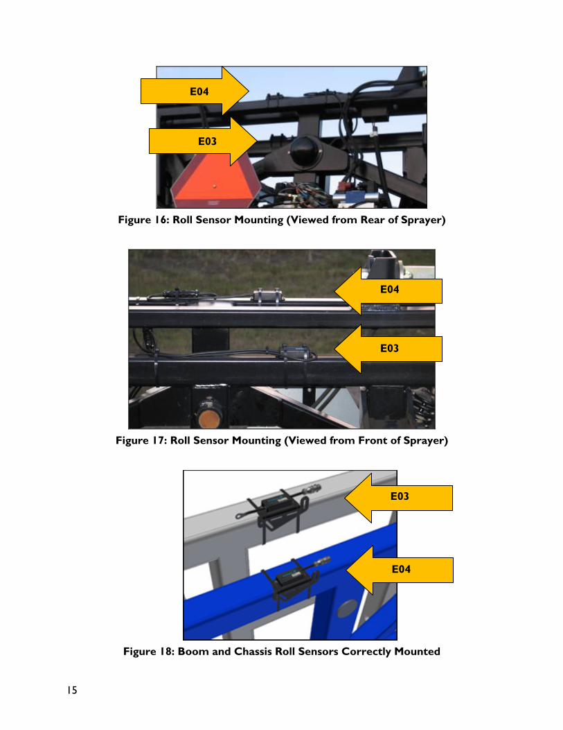
Figure 16: Roll Sensor Mounting (Viewed from Rear of Sprayer)
Figure 17: Roll Sensor Mounting (Viewed from Front of Sprayer)
Figure 18: Boom and Chassis Roll Sensors Correctly Mounted
E04
E03
E03
E04
E03
E04
16
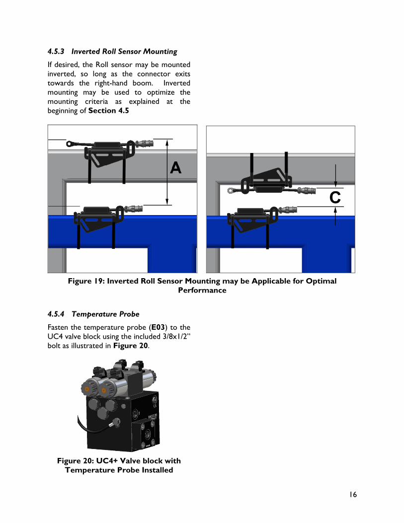
4.5.3 Inverted Roll Sensor Mounting
If desired, the Roll sensor may be mounted inverted, so long as the connector exits towards the right-hand boom. Inverted mounting may be used to optimize the mounting criteria as explained at the beginning of Section 4.5
Figure 19: Inverted Roll Sensor Mounting may be Applicable for Optimal
Performance
4.5.4 Temperature Probe
Fasten the temperature probe (E03) to the UC4 valve block using the included 3/8x1/2” bolt as illustrated in Figure 20.
Figure 20: UC4+ Valve block with
Temperature Probe Installed
17
4.6 HYDRAULIC INSTALLATION
WARNING!
The hydraulic system creates very high pressure. Before disconnecting any hydraulic lines ensure all pressure has been bled from the system. When changing the boom hydraulic hoses leave the booms in TRANSPORT POSITION.
IMPORTANT:
Component failure due to oil contamination is not covered under the UC4+ Spray Height Control system warranty. It is recommended that a qualified technician does the hydraulic installation.
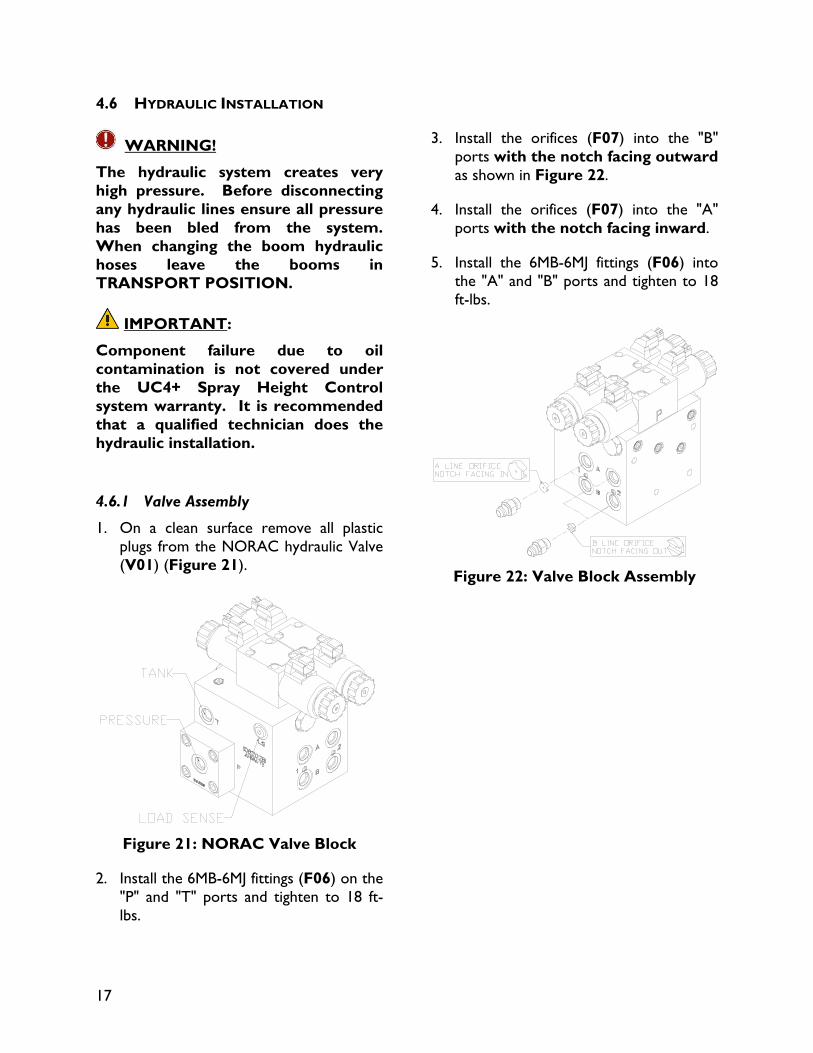
4.6.1 Valve Assembly
1. On a clean surface remove all plastic plugs from the NORAC hydraulic Valve (V01) (Figure 21).
Figure 21: NORAC Valve Block
2. Install the 6MB-6MJ fittings (F06) on the "P" and "T" ports and tighten to 18 ft-lbs.
3. Install the orifices (F07) into the "B" ports with the notch facing outward as shown in Figure 22.
4. Install the orifices (F07) into the "A" ports with the notch facing inward.
5. Install the 6MB-6MJ fittings (F06) into the "A" and "B" ports and tighten to 18 ft-lbs.
Figure 22: Valve Block Assembly
18
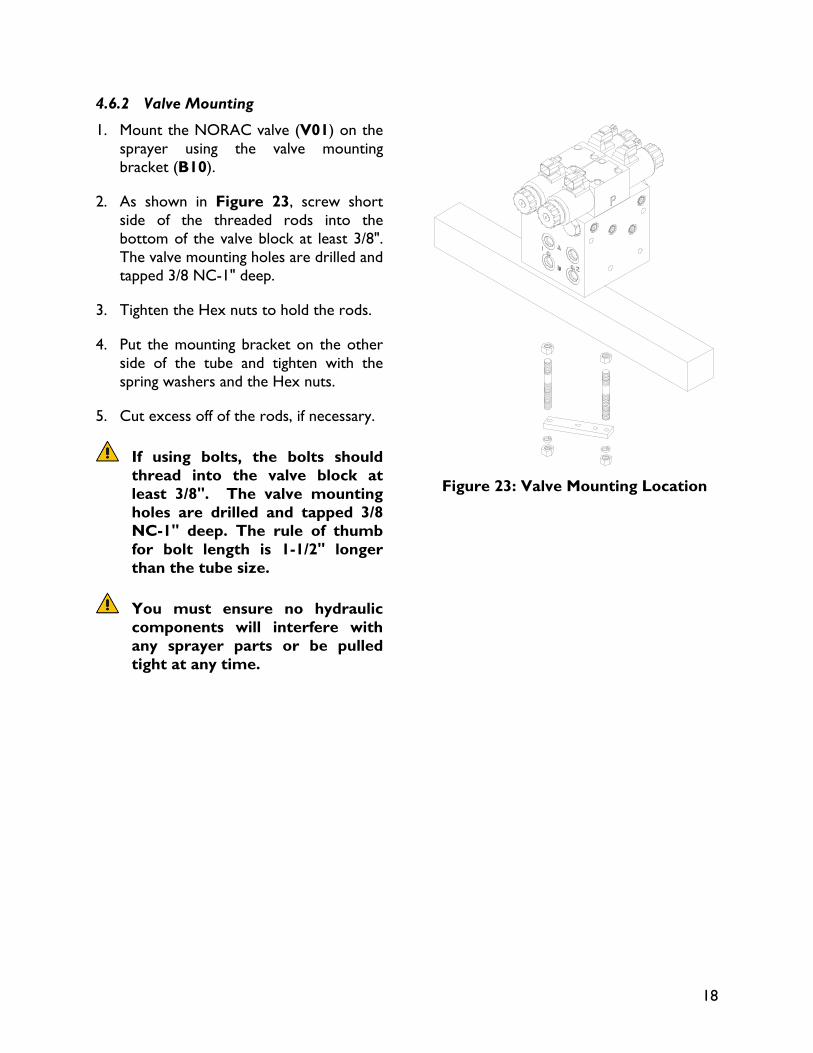
4.6.2 Valve Mounting
1. Mount the NORAC valve (V01) on the sprayer using the valve mounting bracket (B10).
2. As shown in Figure 23, screw short side of the threaded rods into the bottom of the valve block at least 3/8". The valve mounting holes are drilled and tapped 3/8 NC-1" deep.
3. Tighten the Hex nuts to hold the rods.
4. Put the mounting bracket on the other side of the tube and tighten with the spring washers and the Hex nuts.
5. Cut excess off of the rods, if necessary.
If using bolts, the bolts should thread into the valve block at least 3/8". The valve mounting holes are drilled and tapped 3/8 NC-1" deep. The rule of thumb for bolt length is 1-1/2" longer than the tube size.
You must ensure no hydraulic components will interfere with any sprayer parts or be pulled tight at any time.
Figure 23: Valve Mounting Location
19
4.6.3 Hydraulic Plumbing
WARNING!
From this point in the installation the booms will be inoperative until the electronics are fully installed.
You must also ensure there are no other orifices present in the circuit between the NORAC valve block and the boom cylinders.
1. After the NORAC valves are mounted, the hydraulic hoses and fittings can be plumbed. The plumbing for the hydraulic circuit is shown schematically in Figure 3.
2. After the valves are mounted to the sprayer, the hydraulic hoses and fittings can be installed (plumbed). The plumbing for the hydraulic circuit is shown schematically in Figure 3.
3. Connect the NORAC supplied hoses (H04) to the Pressure (“P”) and Tank (“T”) ports on the NORAC valve block (V01). Route both of these lines to the sprayer valve block.
4. Tee in these hoses (“P” and “T” lines) to the ports on the sprayer valve block using F03, F04 and F05.
5. The existing hoses that run to the boom tilt cylinders should be disconnected from the sprayer valve block and reconnected to the NORAC valve block.
a. The “raise” lines from the side of the boom tilt cylinders, which raise the booms, must be connected to the "B" ports of the NORAC valve block. The ports on the sprayer block must then be plugged with the 6MBP plugs (F01).
b. The "A" ports of the NORAC block must be connected to the “lower” lines of the cylinders. The ports on the sprayer block must then be plugged with the 6MBP plugs (F01).
20
4.7 ELECTRICAL INSTALLATION
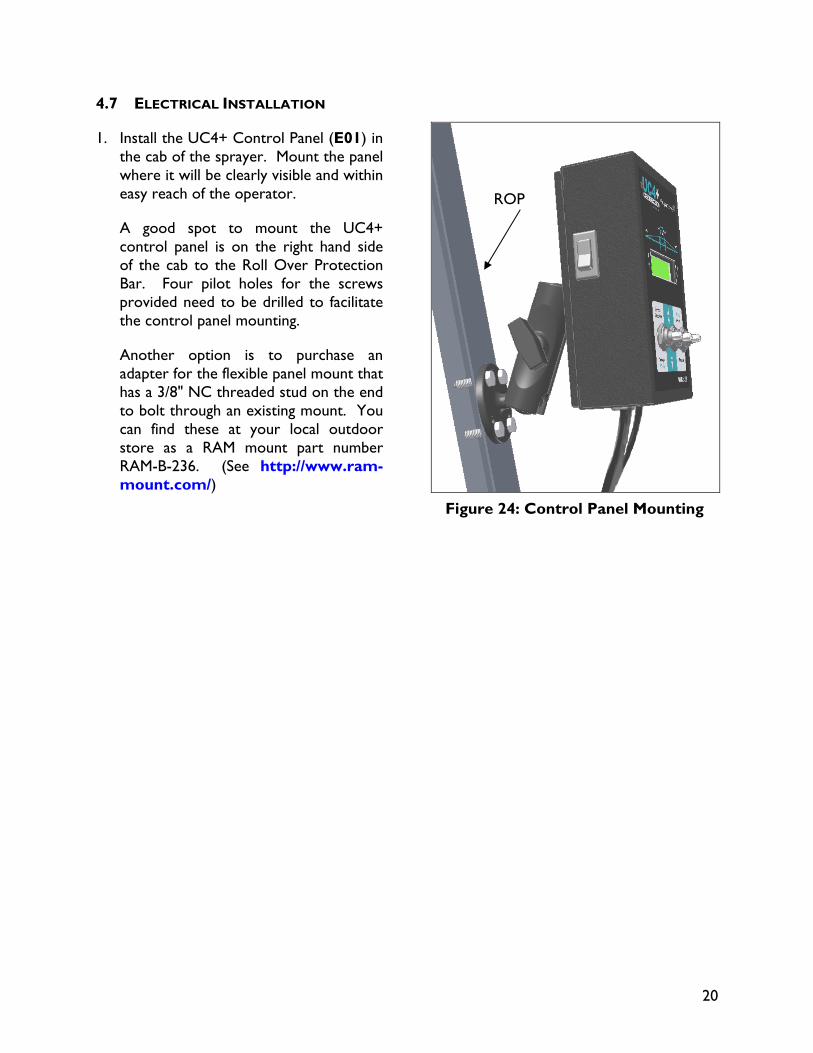
1. Install the UC4+ Control Panel (E01) in the cab of the sprayer. Mount the panel where it will be clearly visible and within easy reach of the operator.
A good spot to mount the UC4+ control panel is on the right hand side of the cab to the Roll Over Protection Bar. Four pilot holes for the screws provided need to be drilled to facilitate the control panel mounting.
Another option is to purchase an adapter for the flexible panel mount that has a 3/8" NC threaded stud on the end to bolt through an existing mount. You can find these at your local outdoor store as a RAM mount part number RAM-B-236. (See http://www.ram-mount.com/)
Figure 24: Control Panel Mounting
ROP
21
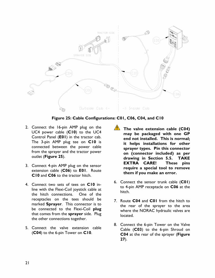
Figure 25: Cable Configurations: C01, C06, C04, and C10
2. Connect the 16-pin AMP plug on the UC4 power cable (C10) to the UC4 Control Panel (E01) in the tractor cab. The 3-pin AMP plug tee on C10 is connected between the power cable from the sprayer and the tractor power outlet (Figure 25).
3. Connect 4-pin AMP plug on the sensor extension cable (C06) to E01. Route C10 and C06 to the tractor hitch.
4. Connect two sets of tees on C10 in-line with the Flexi-Coil joystick cable at the hitch connections. One of the receptacles on the tees should be marked Sprayer. This connector is to be connected to the Flexi-Coil plug that comes from the sprayer side. Plug the other connections together.
5. Connect the valve extension cable (C04) to the 6-pin Tower on C10.
The valve extension cable (C04) may be packaged with one GP end not installed. This is normal; it helps installations for other sprayer types. Pin this connector on (connector included) as per drawing in Section 5.5. TAKE EXTRA CARE! These pins require a special tool to remove them if you make an error.
6. Connect the sensor trunk cable (C01) to 4-pin AMP receptacle on C06 at the hitch.
7. Route C04 and C01 from the hitch to the rear of the sprayer to the area where the NORAC hydraulic valves are located.
8. Connect the 6-pin Tower on the Valve Cable (C03) to the 6-pin Shroud on C04 at the rear of the sprayer (Figure 27).
22
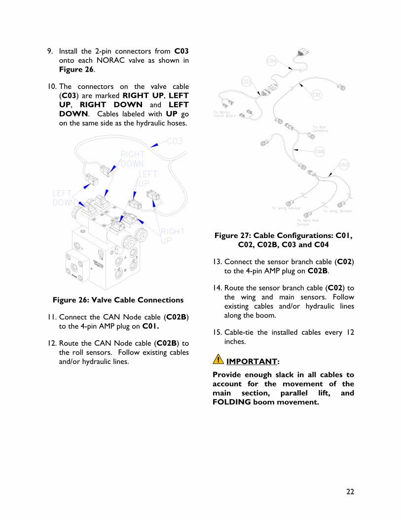
9. Install the 2-pin connectors from C03 onto each NORAC valve as shown in Figure 26.
10. The connectors on the valve cable (C03) are marked RIGHT UP, LEFT UP, RIGHT DOWN and LEFT DOWN. Cables labeled with UP go on the same side as the hydraulic hoses.
Figure 26: Valve Cable Connections
11. Connect the CAN Node cable (C02B) to the 4-pin AMP plug on C01.
12. Route the CAN Node cable (C02B) to the roll sensors. Follow existing cables and/or hydraulic lines.
Figure 27: Cable Configurations: C01,
C02, C02B, C03 and C04
13. Connect the sensor branch cable (C02) to the 4-pin AMP plug on C02B.
14. Route the sensor branch cable (C02) to the wing and main sensors. Follow existing cables and/or hydraulic lines along the boom.
15. Cable-tie the installed cables every 12 inches.
IMPORTANT:
Provide enough slack in all cables to account for the movement of the main section, parallel lift, and FOLDING boom movement.
23
4.8 COMPLETING THE INSTALLATION
1. Start up your sprayer and test the sprayer’s functionality. The NORAC Control Panel does not need to be powered up for the original switches to function. Unfold the booms and raise/lower each boom and main section.
Confirm that the cabling and hoses are agreeable to the entire range of motion.
2. If any functions do not work, review the hydraulic and electrical portions of this manual to check for proper installation. If you still have trouble, contact NORAC for assistance.
3. Turn on the power for the UC4+ Control Panel using the switch on the side of its chassis.
4. Repeat the Boom Speed Test as described in Section 4.2 Boom Speed Test with the NORAC UC4+ System installed. Record the results for comparison in Table 5.
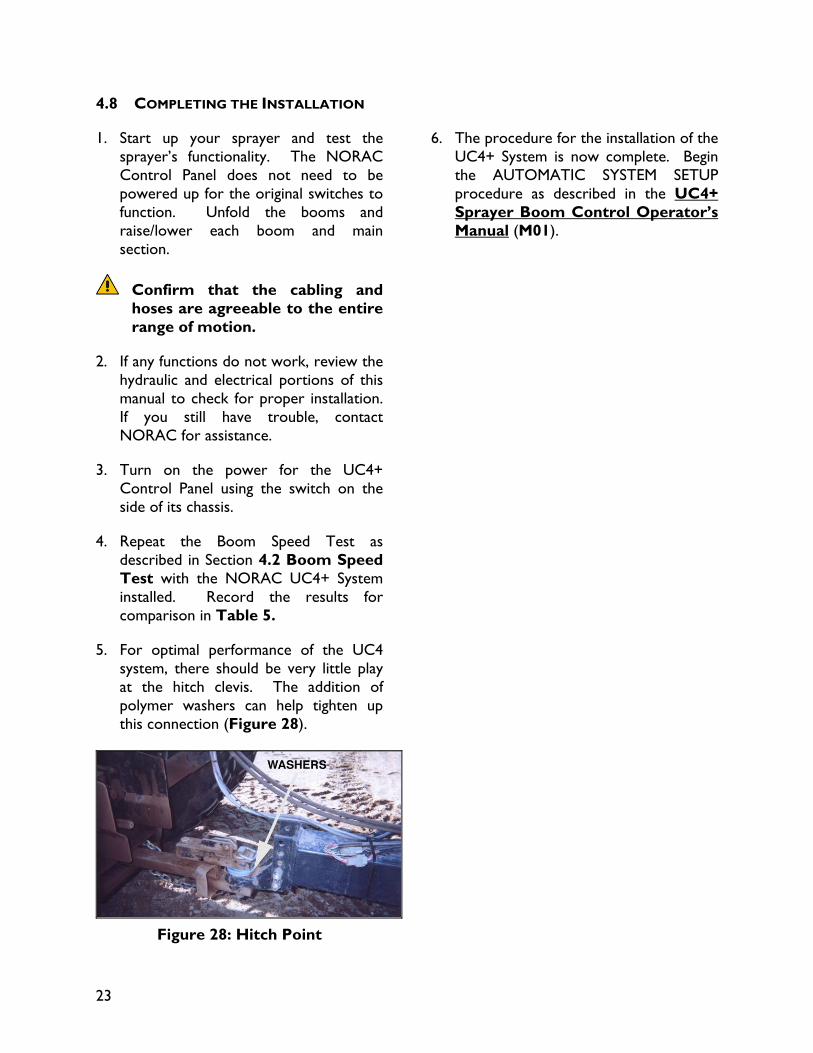
5. For optimal performance of the UC4 system, there should be very little play at the hitch clevis. The addition of polymer washers can help tighten up this connection (Figure 28).
Figure 28: Hitch Point
6. The procedure for the installation of the UC4+ System is now complete. Begin the AUTOMATIC SYSTEM SETUP procedure as described in the UC4+ Sprayer Boom Control Operator’s Manual (M01).
24
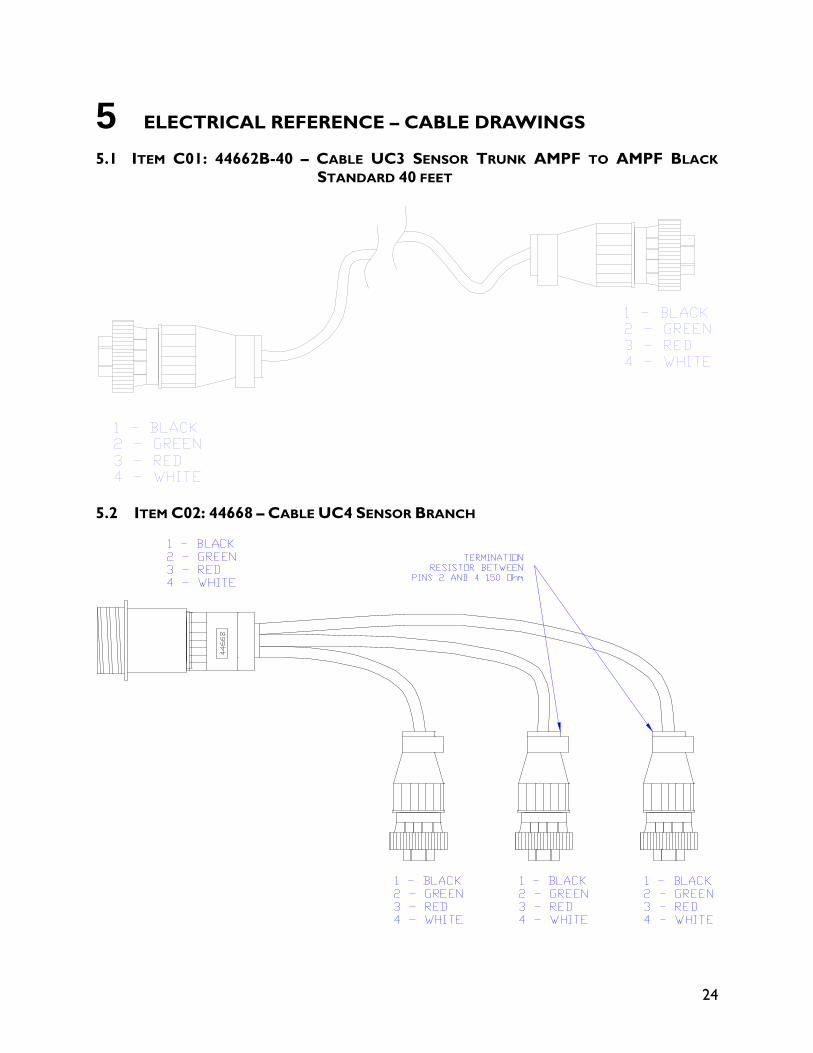
5 ELECTRICAL REFERENCE – CABLE DRAWINGS
5.1 ITEM C01: 44662B-40 – CABLE UC3 SENSOR TRUNK AMPF TO AMPF BLACK
STANDARD 40 FEET
5.2 ITEM C02: 44668 – CABLE UC4 SENSOR BRANCH
25
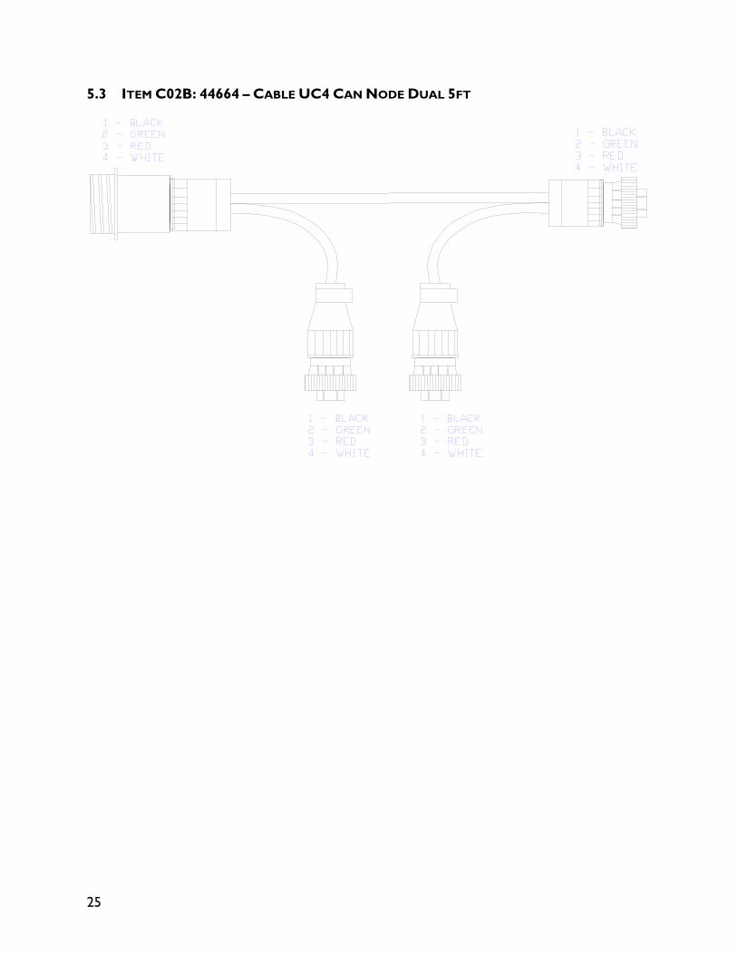
5.3 ITEM C02B: 44664 – CABLE UC4 CAN NODE DUAL 5FT
26
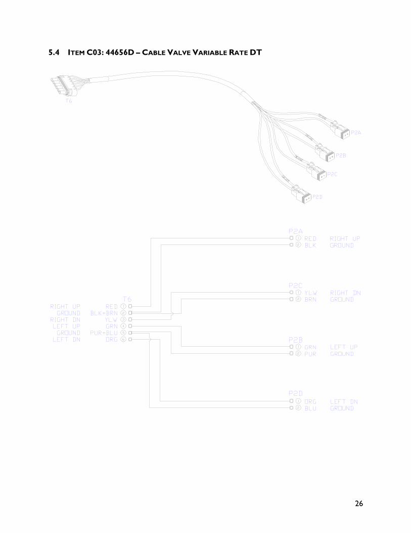
5.4 ITEM C03: 44656D – CABLE VALVE VARIABLE RATE DT
27
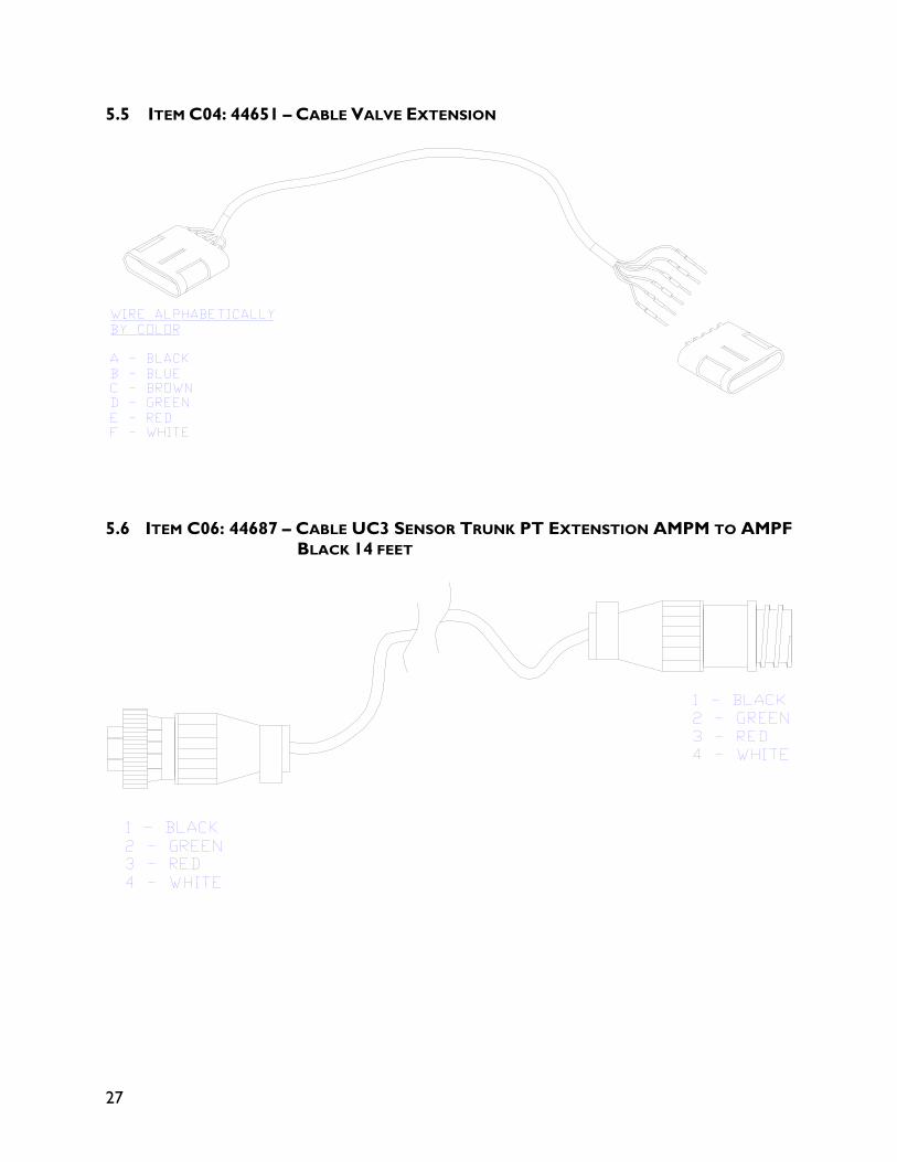
5.5 ITEM C04: 44651 – CABLE VALVE EXTENSION
5.6 ITEM C06: 44687 – CABLE UC3 SENSOR TRUNK PT EXTENSTION AMPM TO AMPF
BLACK 14 FEET
28
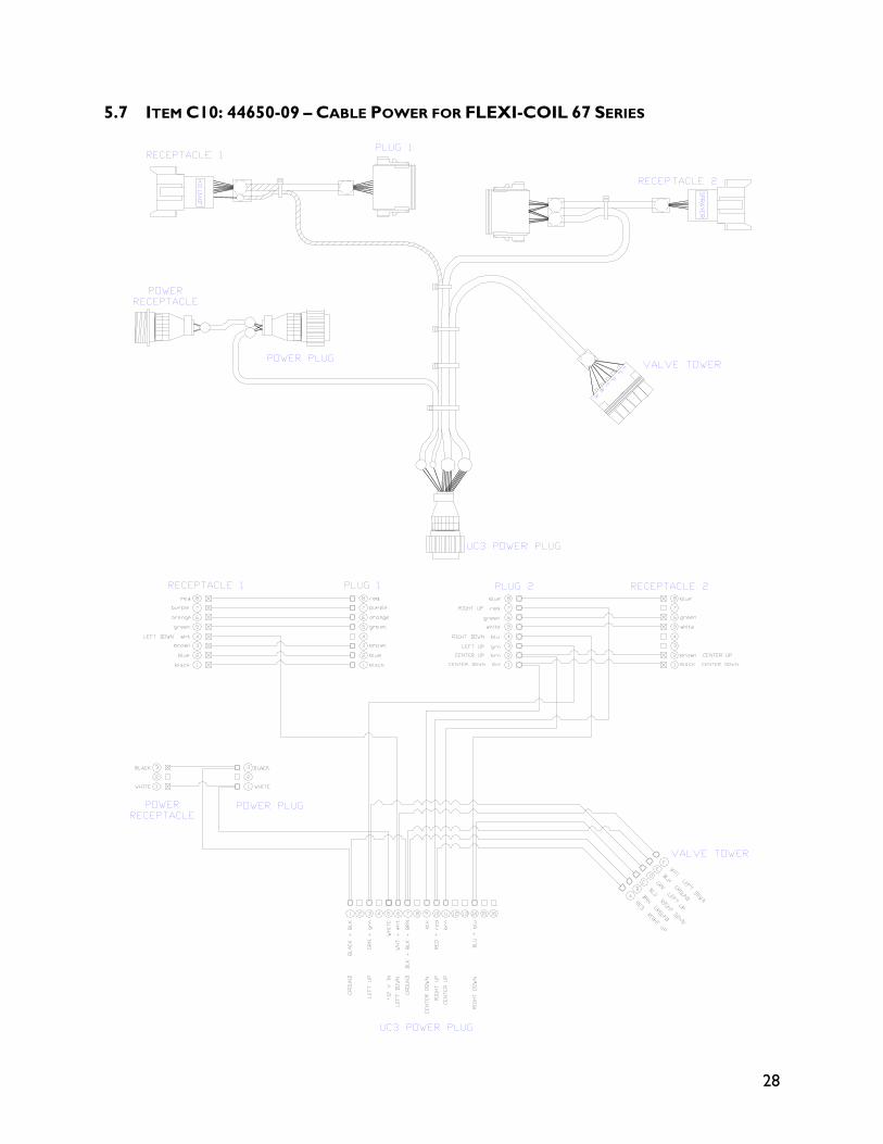
5.7 ITEM C10: 44650-09 – CABLE POWER FOR FLEXI-COIL 67 SERIES
Canada NORAC Systems International Inc.
CALL TOLL FREE: 1-800-667-3921 (306)664-6711
SHIPPING ADDRESS: 3702 Kinnear Place
Saskatoon, SK S7P 0A6
United States NORAC, Inc.
CALL TOLL FREE: 1-866-306-6722 (952)224-4142
SHIPPING ADDRESS: 6667 West Old Shakopee Road, Suite 111
Bloomington, MN 55438
Europe NORAC Europe sarl (+33) (0)4 26 47 04 42
SHIPPING ADDRESS: Rue de l’hermitage
01090 Guereins France
www.norac.ca


![[UC4] Version and Automate Everything](https://img.pdfslide.us/doc/110x75/54918f02b479598e6a8b549b/uc4-version-and-automate-everything.jpg)