Embed Size (px)
Citation preview
SPIC-300SPECTRAL IRRADIANCE
COLORIMETERV 2.00
Everfine Deutschland Vertretung:TIDANIS GmbhAugust ThyssenStr. 3656170 BendorfFon: +49 (0)2622 922 36 [email protected]ändlershop: www.bentrado.de
SPIC-300 Spectral Irradiance colorimeter
Copyright © EVERFINE, Copy or spread without authorization is prohibited.1
ForewordThank you for purchasing the EVERFINE SPIC-300 Spectral Irradiance
Colorimeter. This user’s Manual contains useful information involving the
instrument’s functions and operating procedures as well as precautions that should be
noticed during operation. In order to use the instrument correctly, please read the
manual carefully first, then put it in a right place for quick references.
Notes: EVERFINE pursues a continuing improvement of the performance and
functions of its products, therefore, the contents of this manual may be
changed without prior notice.
Great effort has been made in preparation of this manual to ensure the
accuracy of its contents. If you have any questions or find any errors, please
contact your dealer or EVERFINE sales office.
If you have different understanding to this manual, please refer to the
Technical Service Department of EVERFINE.
Checking package contentsPlease check the instrument carefully when you unpack the box for the first time.
If the instrument and related accessories are missing or appear abnormal, please
contact the dealer immediately.
Warm notice to valued customers of EVERFINE"Ensure the quality, insist on continuous improvement and make every customer
more satisfied" is the quality policy of EVERFINE. Therefore, the quality of
products and services provided by EVERFINE should be better than those have
been promised. If you have further suggestions or advices on our products and
services, please provide your feedback to our quality supervision department.
Your supervision is the motivation for us to move forward!

SPIC-300 Spectral Irradiance colorimeter
Copyright © EVERFINE, Copy or spread without authorization is prohibited.2
Copyright StatementThe copyright of this manual and the related information belongs to
EVERFINE, and it is protected by the copyright law of the People’s Republic of
China and other relevant international treaties. Copying, modifying, spreading,
excerpting, backing up or translating the whole or part contents of this manual
by any company or personnel without the written permission of EVERFINE is
prohibited. Otherwise it will be treated as infringement and the infringer will
assume law responsibility and all loss of EVERFINE. Any infringement related
above can be traced back to the responsible user by the unique product number
printed in the manual.
If EVERFINE has signed a written agreement with user and the contents in
the agreement are in conflict with above terms, the contents in the written
agreement have preferential force effect.

SPIC-300 Spectral Irradiance colorimeter
Copyright © EVERFINE, Copy or spread without authorization is prohibited.3
Safety PrecautionsPrecautions:
Do not place anything on the top of the instrument, especially objectscontaining iron filings, water and oil etc. Otherwise, it may results insevere consequences.
Do not bend the USB cable. To avoid high internal temperature, do not block the vent holes in the
instrument case. Do not open the case of the instrument to ensure the safety of user and
instrument. When the instrument needs internal inspection or adjustment,please contact your dealer or EVERFINE representative.
If you notice smoke or unusual odors coming from the instrument,immediately turn OFF the power and remove the battery. Please contactyour dealer or the EVERFINE representative.
If the battery power is low, please charge it by the original charger. Ifbattery is always in the over discharge condition, it will reduce thelifetime. If the instrument will be stored for a long period, keep thebattery power within 40%-80%, then remove it from the instrument andstore in a dry environment at room temperature.
Storage environment:
Please do not store the instrument in places where it may be exposed to any of
the following conditions.
Relative humidity:>65%RH; temperature:>45℃ Excessive vibration Splashes of water, oil or chemicals heat sources Direct sunlight Excessive amount of dust, dirt, salt or iron filings
Operation environment:
Relative humidity:65% RH ± 20% RH;Temperature:(0~35)℃
Avoid mechanical vibration Keep away from water, oil or chemicals heat sources, salt or iron filings
field and electric field. Avoid excessive amount of dust, dirt, corrosive or flammable gases Avoid Direct sunlight
Quantity calibration:

SPIC-300 Spectral Irradiance colorimeter
Copyright © EVERFINE, Copy or spread without authorization is prohibited.4
To ensure high measurement accuracy, it is recommended that the
instrument should be calibrated in EVERFINE Test and Calibration Center or
other laboratory which owns the calibration accreditation for spectrum and
photometric parameters.
Recommend Calibration period: Once a year.
To ensure high measurement accuracy, the instrument is recommended to
operate on the following conditions: Temperature of 15 °C ~25°C; Humidity:
50%RH~75%RH
SPIC-300 Spectral Irradiance colorimeter
Copyright © EVERFINE, Copy or spread without authorization is prohibited.5
ContentsFOREWORD............................................................................................................................................1
COPYRIGHT STATEMENT..................................................................................................................2
SAFETY PRECAUTIONS...................................................................................................................... 3
CONTENTS.............................................................................................................................................. 5
CHAPTER 1 OVERVIEWS.................................................................................................................... 7
CHAPTER 2 SPECIFICATIONS.......................................................................................................... 9
2.1 MEASURABLE ITEMS:........................................................................................................................92.2 TECHNICAL SPECIFICATIONS........................................................................................................... 10
CHAPTER 3 INSTRUMENT INTRODUCTION............................................................................... 11
3.1 INSTRUMENT CONFIGURATION....................................................................................................... 113.2 INSTALLATION AND DISMOUNTING OF DETECTOR...........................................................................143.3 DETECTOR INDICATOR.................................................................................................................... 14
CHAPTER 4 OPERATION GUIDE.................................................................................................... 15
4.1 START THE INSTRUMENT................................................................................................................ 154.2 COMMON MEASURE........................................................................................................................164.3 CONTINOUS MEASUREMENT........................................................................................................... 214.4 COMPARING MEASUREMENT.......................................................................................................... 224.5 SETTING..........................................................................................................................................234.5.1 Test setting.............................................................................................................................. 244.5.2 System setting.........................................................................................................................264.5.3 Zero setting............................................................................................................................. 294.5.4 About...................................................................................................................................... 30
4.6 FILE MANAGEMENT........................................................................................................................ 314.7 KNOWLEDGE.................................................................................................................................. 324.8 SPECTRAL CALIBRATION.................................................................................................................334.9 ILLUMINATION CALIBRATION......................................................................................................... 344.10 COMMUNICATION WITH PC...........................................................................................................35
CHAPTER 5 PC SOFTWARE INSTRUCTION.................................................................................36
5.1 PC SOFTWARE INSTALLATION......................................................................................................... 365.2 SOFTWARE OVERVIEW.................................................................................................................... 365.2.1 Software start..........................................................................................................................365.2.2 Main interface introduction.................................................................................................... 37
5.3 TEST................................................................................................................................................385.3.1 System setting.........................................................................................................................385.3.2 Test..........................................................................................................................................405.3.3 Type diagram.......................................................................................................................... 405.3.4Test information Modification.................................................................................................425.3.5 Test result output and print..................................................................................................... 435.3.6 Cloud operation......................................................................................错误!未定义书签。
CHAPTER 6 INSTRUMENT VERIFICATION................................................................................. 45
6.1 VERIFICATION CONDITIONS.............................................................................................................456.1.1 Working conditions.................................................................................................................456.1.2 Apparatus................................................................................................................................ 45
6.2 ITEMS AND METHODS..................................................................................................................... 456.2.1 Verification of wavelength accuracy...................................................................................... 456.2.2 Verification of chromaticity coordinates accuracy................................................................. 466.2.3 Verification of photometric channel linearity.........................................................................466.2.4 Verification of stray light........................................................................................................47

SPIC-300 Spectral Irradiance colorimeter
Copyright © EVERFINE, Copy or spread without authorization is prohibited.6
CHAPTER 7 COMMON FAULTS...................................................................................................... 48
CHAPTER 8 TYPICAL TEST REPORT.............................................................................................49

SPIC-300 Spectral Irradiance colorimeter
Copyright © EVERFINE, Copy or spread without authorization is prohibited.7
Chapter 1 OverviewsSPIC-300 Spectral Irradiance Colorimeter can realize the measurement of the
spectrum, illuminance, colorimetric and photometric quantities etc. With a series of
international patented technologies, the instrument realizes excellent linearity in the
measurement of wide dynamic range
The detector can be separated from the main unit of SPIC-300, realizing super
measurement flexibility. The equiped 5'' touch screen, large storage space and the
android operating system etc..makes the measurement more intelligent. All the
quantities could be measured and displayed by one touch, which suits best for the
on-site measurements of road, indoor, commercial, office and plant growing lighting
etc., as well as the research and development field of lighting products, production
line controlling, etc..
Main Characteristics of SPIC-300:
1) The Spectrometer & Broadband-radiometer/photometer Combined
Technique (SBCT) and stray light correction patented technologies make SPIC-300
realizing high measurement accuracy and excellent linearity;
2) The measurement speed is finished in several milliseconds, during which all
the spectral radiometric, photometric, colorimetric quantities can be obtained;
3) The detector and the main unit can be integrated in whole, or separated and
the communication between the detector and the main unit is realizes by a USB or
WIFI , which is suitable for the remote measurement.
4) The software can be customized for extended functions in compliance with
the latest standards or the requirements of customer, such as the IES equivalent
illuminance and phytometric measurements;
5) The 5" color capacitive touch screen wided the vision and simplfied the
operation with fingertip;
6) The data can be exported as “Excel” and “JPG” etc. formats, and it is
convenient for view and edit;
7) The large storage space can be used for storing the history data and the
on-line test data, which is convenient for on-site analysis and comparisons as well as
data transmission.
8) The compact design makes it handheld and portable;

SPIC-300 Spectral Irradiance colorimeter
Copyright © EVERFINE, Copy or spread without authorization is prohibited.8
9) Equipped with a high capacity and rechargeable lithium ion battery
(3300mAh), it can be continuously operated for field measurement.
10) Powerful software function, it can automatically finish the quality
verification automatically according to test results
11) The software owns functions like sending e-mail, updating on-line

SPIC-300 Spectral Irradiance colorimeter
Copyright © EVERFINE, Copy or spread without authorization is prohibited.9
Chapter 2 Specifications
2.1 Measurable items:1) Relative Spectral Power Distribution P(λ)
2) Spectral Irradiance E(λ)
3) Chromaticity Coordinates:(x,y)、(u,v)、(u’,v’)
4) Correlated Color Temperature:Tc
5) Color Rendering Index: Ra, Ri(i=1~15)
6) Standard Deviation of Color Matching (SDCM)
7) Peak wavelength, Full width at half maximum (FWHM)
8) Spectral Purity, Dominate Wavelength
9) Red ratio
10) Illuminance E、Irradiance Ee
11) Available to customized more measurement functions.
SPIC-300 Spectral Irradiance colorimeter
Copyright © EVERFINE, Copy or spread without authorization is prohibited.10
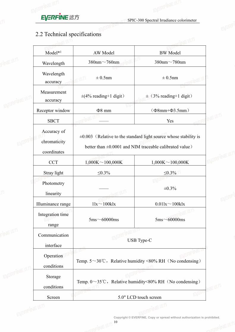
2.2 Technical specifications
Model*1 AWModel BWModel
Wavelength 380nm~760nm 380nm~780nm
Wavelength
accuracy± 0.5nm ± 0.5nm
Measurement
accuracy±(4% reading+1 digit) ±(3% reading+1 digit)
Receptor window Ф8 mm (Ф8mm+Ф3.5mm)
SBCT —— Yes
Accuracy of
chromaticity
coordinates
±0.003(Relative to the standard light source whose stability is
better than ±0.0001 and NIM traceable calibrated value)
CCT 1,000K~100,000K 1,000K~100,000K
Stray light ≤0.3% ≤0.3%
Photometry
linearity—— ±0.3%
Illuminance range 1lx~100klx 0.01lx~100klx
Integration time
range5ms~60000ms 5ms~60000ms
Communication
interfaceUSB Type-C
Operation
conditionsTemp. 5~30℃,Relative humidity <80% RH(No condensing)
Storage
conditionsTemp. 0~35℃,Relative humidity<80% RH(No condensing)
Screen 5.0" LCD touch screen
SPIC-300 Spectral Irradiance colorimeter
Copyright © EVERFINE, Copy or spread without authorization is prohibited.11
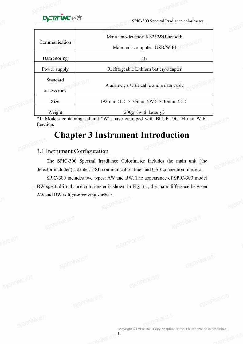
CommunicationMain unit-detector: RS232&Bluetooth
Main unit-computer: USB/WIFI
Data Storing 8G
Power supply Rechargeable Lithium battery/adapter
Standard
accessoriesA adapter, a USB cable and a data cable
Size 192mm(L)× 76mm(W)× 30mm(H)
Weight 200g(with battery)*1. Models containing subunit “W”, have equipped with BLUETOOTH and WIFIfunction.
Chapter 3 Instrument Introduction
3.1 Instrument ConfigurationThe SPIC-300 Spectral Irradiance Colorimeter includes the main unit (the
detector included), adapter, USB communication line, and USB connection line, etc.
SPIC-300 includes two types: AW and BW. The appearance of SPIC-300 model
BW spectral irradiance colorimeter is shown in Fig. 3.1, the main difference between
AW and BW is light-receiving surface .
SPIC-300 Spectral Irradiance colorimeter
Copyright © EVERFINE, Copy or spread without authorization is prohibited.12
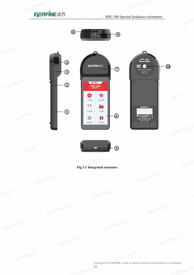
Fig 3.1 Integrated structure
○3
○6
○7○4
○5
○1
○2
○8 ○9
○10
SPIC-300 Spectral Irradiance colorimeter
Copyright © EVERFINE, Copy or spread without authorization is prohibited.13
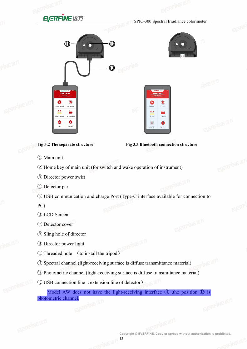
Fig 3.2 The separate structure Fig 3.3 Bluetooth connection structure
①Main unit
② Home key of main unit (for switch and wake operation of instrument)
③ Director power swift
④ Detector part
⑤ USB communication and charge Port (Type-C interface available for connection to
PC)
⑥ LCD Screen
⑦ Detector cover
⑧ Sling hole of director
⑨ Director power light
⑩ Threaded hole (to install the tripod)
⑪ Spectral channel (light-receiving surface is diffuse transmittance material)
⑫ Photometric channel (light-receiving surface is diffuse transmittance material)
⑬ USB connection line(extension line of detector)
Model AW does not have the light-receiving interface ⑪ ,the position ⑫ isphotometric channel.
○12
○13
○11
SPIC-300 Spectral Irradiance colorimeter
Copyright © EVERFINE, Copy or spread without authorization is prohibited.14
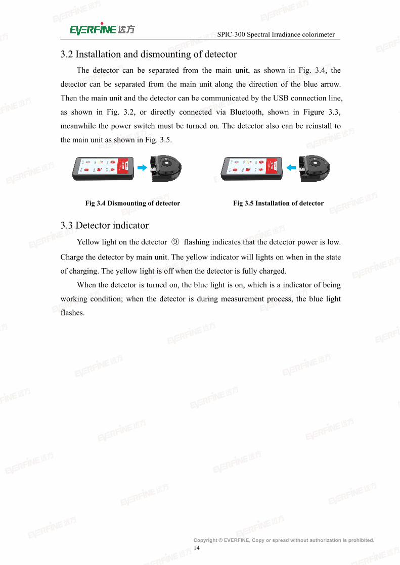
3.2 Installation and dismounting of detectorThe detector can be separated from the main unit, as shown in Fig. 3.4, the
detector can be separated from the main unit along the direction of the blue arrow.
Then the main unit and the detector can be communicated by the USB connection line,
as shown in Fig. 3.2, or directly connected via Bluetooth, shown in Figure 3.3,
meanwhile the power switch must be turned on. The detector also can be reinstall to
the main unit as shown in Fig. 3.5.
Fig 3.4 Dismounting of detector Fig 3.5 Installation of detector
3.3 Detector indicatorYellow light on the detector ⑨ flashing indicates that the detector power is low.
Charge the detector by main unit. The yellow indicator will lights on when in the state
of charging. The yellow light is off when the detector is fully charged.
When the detector is turned on, the blue light is on, which is a indicator of being
working condition; when the detector is during measurement process, the blue light
flashes.
SPIC-300 Spectral Irradiance colorimeter
Copyright © EVERFINE, Copy or spread without authorization is prohibited.15
Chapter 4 Operation GuideThe main unit is based on android operation system and the interface is friendly
and clear, user can finish the parameters setting, zero calibration and measurements
etc. step by step according to the following prompts.
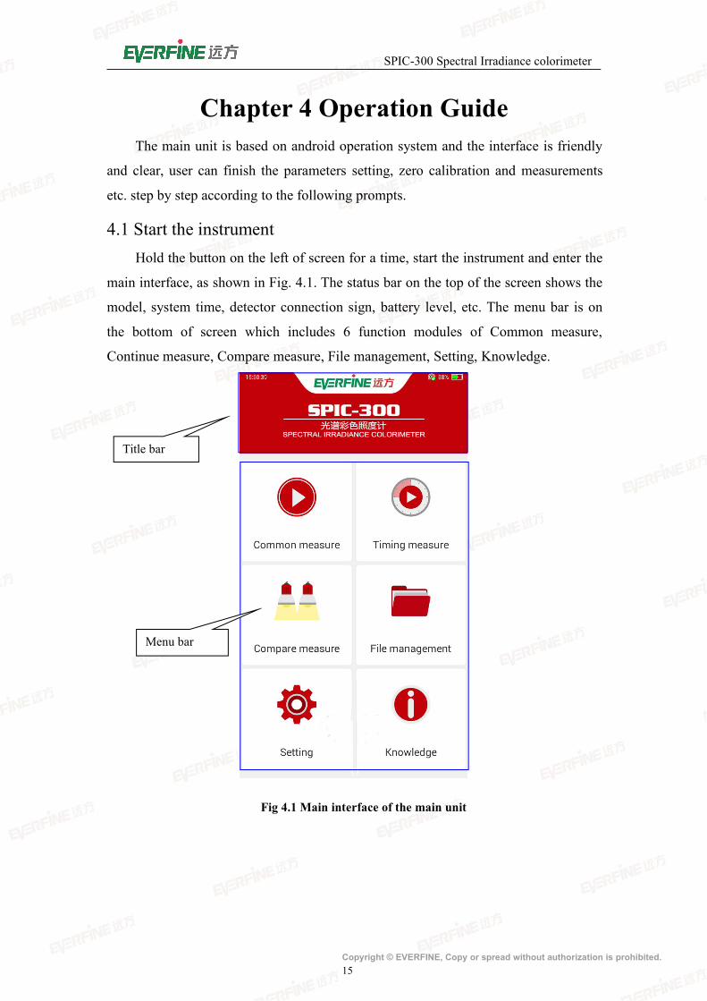
4.1 Start the instrumentHold the button on the left of screen for a time, start the instrument and enter the
main interface, as shown in Fig. 4.1. The status bar on the top of the screen shows the
model, system time, detector connection sign, battery level, etc. The menu bar is on
the bottom of screen which includes 6 function modules of Common measure,
Continue measure, Compare measure, File management, Setting, Knowledge.
Fig 4.1 Main interface of the main unit
Title bar
Menu bar
SPIC-300 Spectral Irradiance colorimeter
Copyright © EVERFINE, Copy or spread without authorization is prohibited.16
4.2 Common measure
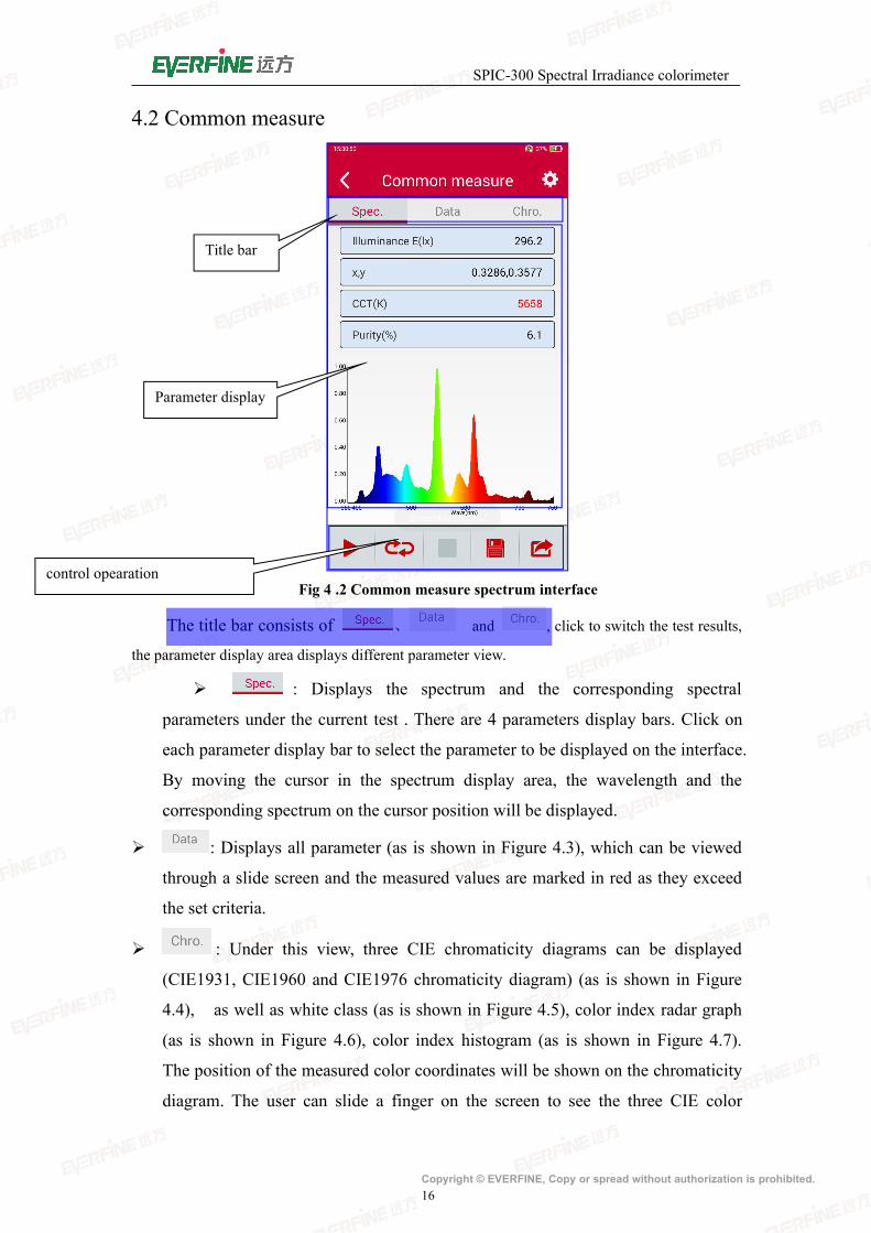
Fig 4 .2 Common measure spectrum interface
The title bar consists of 、 and , click to switch the test results,
the parameter display area displays different parameter view.
: Displays the spectrum and the corresponding spectral
parameters under the current test . There are 4 parameters display bars. Click on
each parameter display bar to select the parameter to be displayed on the interface.
By moving the cursor in the spectrum display area, the wavelength and the
corresponding spectrum on the cursor position will be displayed.
: Displays all parameter (as is shown in Figure 4.3), which can be viewed
through a slide screen and the measured values are marked in red as they exceed
the set criteria.
: Under this view, three CIE chromaticity diagrams can be displayed
(CIE1931, CIE1960 and CIE1976 chromaticity diagram) (as is shown in Figure
4.4), as well as white class (as is shown in Figure 4.5), color index radar graph
(as is shown in Figure 4.6), color index histogram (as is shown in Figure 4.7).
The position of the measured color coordinates will be shown on the chromaticity
diagram. The user can slide a finger on the screen to see the three CIE color
Title bar
Parameter display
control opearation
SPIC-300 Spectral Irradiance colorimeter
Copyright © EVERFINE, Copy or spread without authorization is prohibited.17
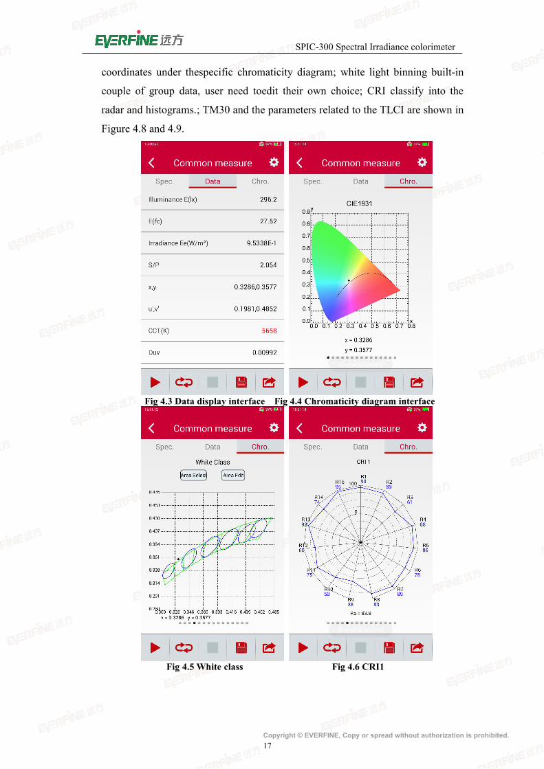
coordinates under thespecific chromaticity diagram; white light binning built-in
couple of group data, user need toedit their own choice; CRI classify into the
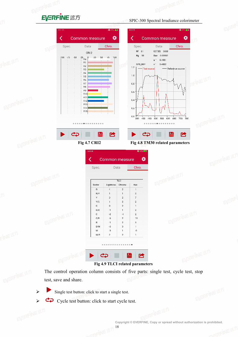
radar and histograms.; TM30 and the parameters related to the TLCI are shown in
Figure 4.8 and 4.9.
Fig 4.3 Data display interface Fig 4.4 Chromaticity diagram interface
Fig 4.5 White class Fig 4.6 CRI1
SPIC-300 Spectral Irradiance colorimeter
Copyright © EVERFINE, Copy or spread without authorization is prohibited.18
Fig 4.7 CRI2 Fig 4.8 TM30 related parameters
Fig 4.9 TLCI related parameters
The control operation column consists of five parts: single test, cycle test, stop
test, save and share.
Single test button: click to start a single test.
Cycle test button: click to start cycle test.
SPIC-300 Spectral Irradiance colorimeter
Copyright © EVERFINE, Copy or spread without authorization is prohibited.19
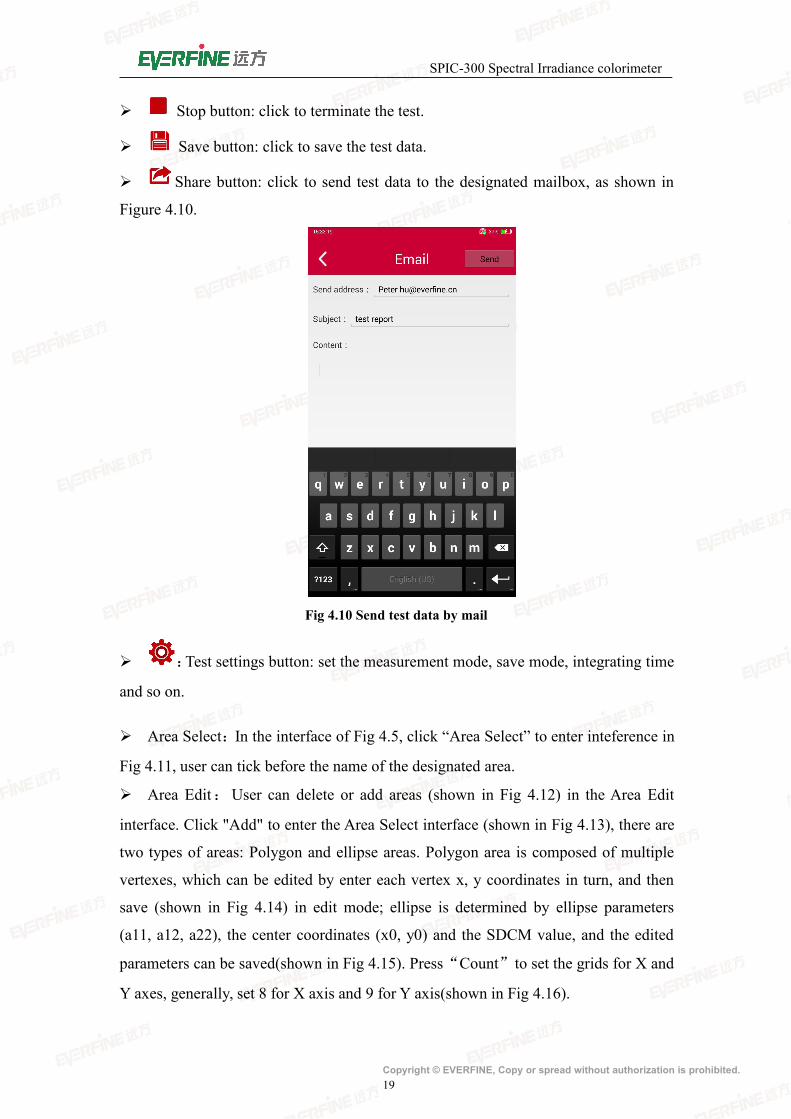
Stop button: click to terminate the test.
Save button: click to save the test data.
Share button: click to send test data to the designated mailbox, as shown in
Figure 4.10.
Fig 4.10 Send test data by mail
:Test settings button: set the measurement mode, save mode, integrating time
and so on.
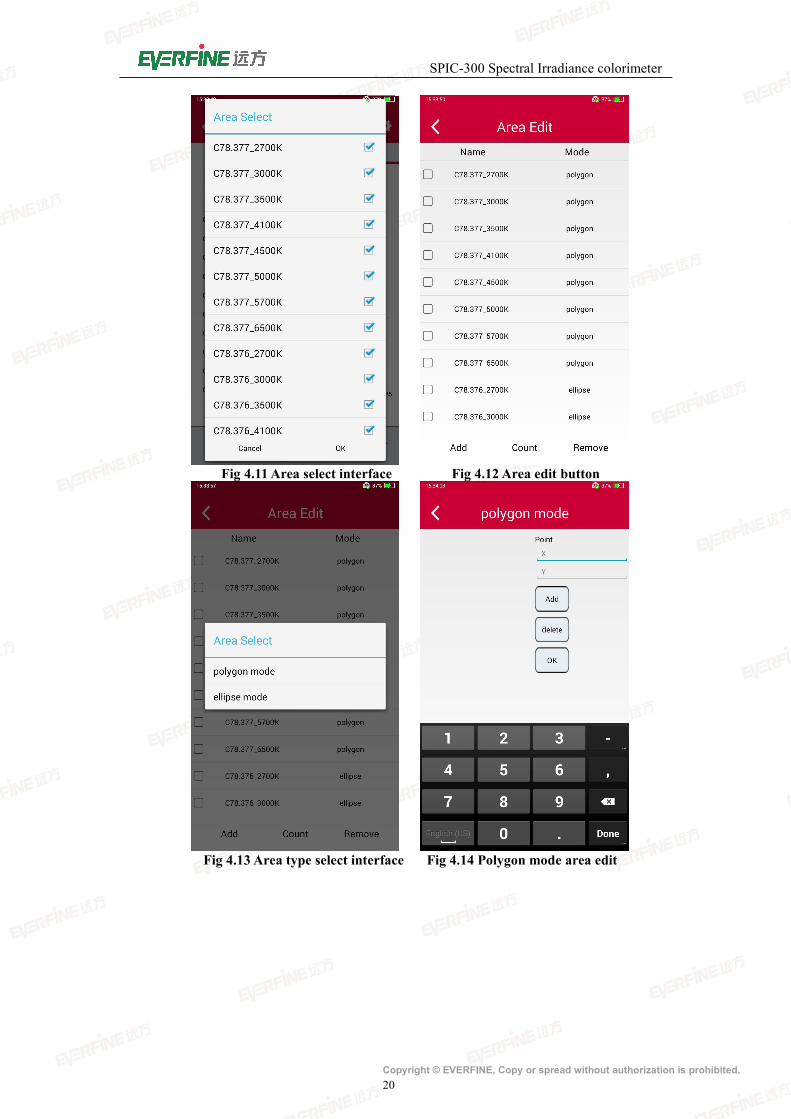
Area Select:In the interface of Fig 4.5, click “Area Select” to enter inteference in
Fig 4.11, user can tick before the name of the designated area.
Area Edit:User can delete or add areas (shown in Fig 4.12) in the Area Edit
interface. Click "Add" to enter the Area Select interface (shown in Fig 4.13), there are
two types of areas: Polygon and ellipse areas. Polygon area is composed of multiple
vertexes, which can be edited by enter each vertex x, y coordinates in turn, and then
save (shown in Fig 4.14) in edit mode; ellipse is determined by ellipse parameters
(a11, a12, a22), the center coordinates (x0, y0) and the SDCM value, and the edited
parameters can be saved(shown in Fig 4.15). Press“Count”to set the grids for X and
Y axes, generally, set 8 for X axis and 9 for Y axis(shown in Fig 4.16).
SPIC-300 Spectral Irradiance colorimeter
Copyright © EVERFINE, Copy or spread without authorization is prohibited.20
Fig 4.11Area select interface Fig 4.12 Area edit button
Fig 4.13 Area type select interface Fig 4.14 Polygon mode area edit

SPIC-300 Spectral Irradiance colorimeter
Copyright © EVERFINE, Copy or spread without authorization is prohibited.21
Fig 4.15 Ellipse model area edit Fig 4.16 Grids Setting
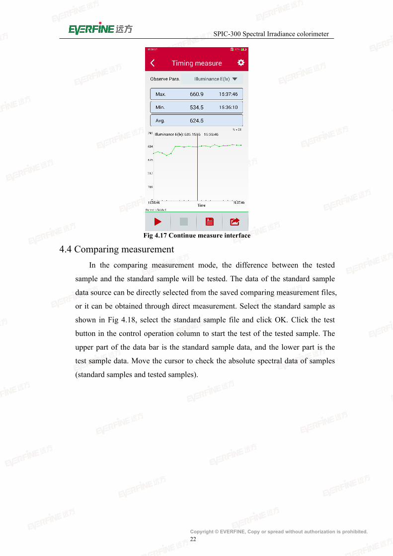
4.3 Continous measurementTest the change of parameters in a period, the test result is as shown in Fig
4.17, click the drop-down list of the observation parameter to select the
parameters concerned and the maximum value, the minimum value, the average
and test time will be displayed. Check the parameter value at the designed time
by moving the cursor.
SPIC-300 Spectral Irradiance colorimeter
Copyright © EVERFINE, Copy or spread without authorization is prohibited.22
Fig 4.17 Continue measure interface
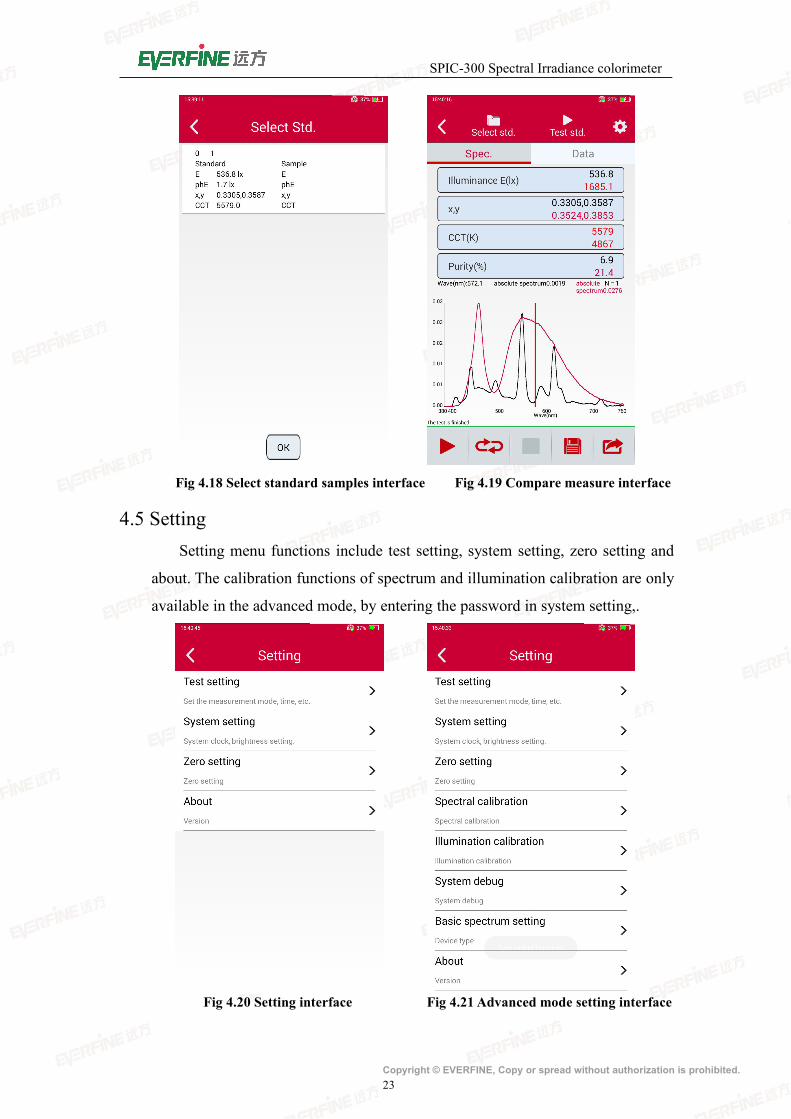
4.4 Comparing measurementIn the comparing measurement mode, the difference between the tested
sample and the standard sample will be tested. The data of the standard sample
data source can be directly selected from the saved comparing measurement files,
or it can be obtained through direct measurement. Select the standard sample as
shown in Fig 4.18, select the standard sample file and click OK. Click the test
button in the control operation column to start the test of the tested sample. The
upper part of the data bar is the standard sample data, and the lower part is the
test sample data. Move the cursor to check the absolute spectral data of samples
(standard samples and tested samples).
SPIC-300 Spectral Irradiance colorimeter
Copyright © EVERFINE, Copy or spread without authorization is prohibited.23
Fig 4.18 Select standard samples interface Fig 4.19 Compare measure interface
4.5 SettingSetting menu functions include test setting, system setting, zero setting and
about. The calibration functions of spectrum and illumination calibration are only
available in the advanced mode, by entering the password in system setting,.
Fig 4.20 Setting interface Fig 4.21 Advanced mode setting interface

SPIC-300 Spectral Irradiance colorimeter
Copyright © EVERFINE, Copy or spread without authorization is prohibited.24
4.5.1 Test setting
Click “Test setting” to enter test setting interface (as is shown in Fig 4.22).
Fig4.22 Test setting interface
a. Save mode:Manual save and auto save。
Manual save:Users need to click “ ” to save the test results.
Auto save:After the test is completed, the data will be automatically saved.
Note: Long time use of auto save mode will make SD memory card data
overflow and can not be saved. Please use it prudently.
b. Integration mode:Auto integration and fixed integration
Auto integration:When testing, the instrument automatically selects the
appropriate integral time according to the intensity of the light signal.
Fixed integration:User sets the integral time according to the intensity of the
measured light signal.
c. Integral time: The setting is valid when the fixed integral is selected. It is
suggested that users set the integral time according to the intensity of the
measured light signal.
Note: When selecting the integral time, on one hand, the signal should
be ensured not overflow, on the other hand, the signal can not be too

SPIC-300 Spectral Irradiance colorimeter
Copyright © EVERFINE, Copy or spread without authorization is prohibited.25
small, otherwise the accuracy of the test will be affected. The basis for
judging whether the time of integration is appropriate is that the Ip
value on the data display interface is more than 50% namely more than
30000 on the data display interface. When the Ip value is small, increase
the integral time and when Ip value is too large, reduce the integral
time.
d. Automatic integral upper limit: When selecting automatic integration, the upper
limit of integral time can be set to 1000~60000ms.
e. Average times: Set the average times of tests, the software will automatically
calculate the average as the current measurement result .
f. Timing measurement time: Set the total test time under the timing measurement
function.
g. Timing interval: Set the time interval between the two measurements under the
timing measurement function.
h. Qualification: User define the file including the upper and lower limits of
parameters , and when the test is completed, the qualification will be judged
according to the file selected by the user. The parameter falling outside the limit
range is marked in red. As Fig 4.23 and Fig 4.24 shows is the editor interface
and and the “file select” interface.
Fig 4.23 Editor Fig 4.24 File select
SPIC-300 Spectral Irradiance colorimeter
Copyright © EVERFINE, Copy or spread without authorization is prohibited.26
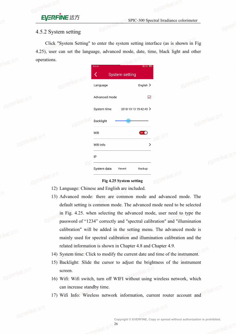
4.5.2 System setting
Click "System Setting" to enter the system setting interface (as is shown in Fig
4.25), user can set the language, advanced mode, date, time, black light and other
operations.
Fig 4.25 System setting
12) Language: Chinese and English are included.
13) Advanced mode: there are common mode and advanced mode. The
default setting is common mode. The advanced mode need to be selected
in Fig. 4.25. when selecting the advanced mode, user need to type the
password of “1234” correctly and "spectral calibration" and "illumination
calibration" will be added in the setting menu. The advanced mode is
mainly used for spectral calibration and illumination calibration and the
related information is shown in Chapter 4.8 and Chapter 4.9.
14) System time: Click to modify the current date and time of the instrument.
15) Backlight: Slide the cursor to adjust the brightness of the instrument
screen.
16) Wifi: Wifi switch, turn off WIFI without using wireless network, which
can increase standby time.
17) Wifi Info: Wireless network information, current router account and

SPIC-300 Spectral Irradiance colorimeter
Copyright © EVERFINE, Copy or spread without authorization is prohibited.27
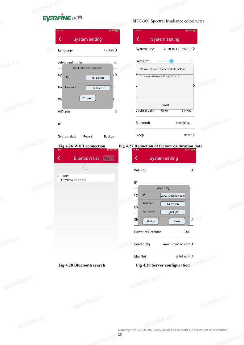
password connected to instrument, and automatically assigned IP
addresses are displayed after the connection, as shown in Fig 4.26.
18) System data: SD card built in the instrument saves dedicated calibration
data files. The content in file will be modified in the operation of spectral
calibration, zero correction. The system data has one key backup and one
key restore function, and has backup data before leaving the factory (the
name is Factory data). Users can back up the system data files on their
own one button: click "backup", enter the name and confirm, then the
backup data files will be saved in the SD card. In the advanced mode, the
"restore" button will appear on the right side of the Backup button (as
shown in Fig 4.25), and click the backup file name to complete the
restore operation (as shown in Fig 4.27). The backup data or the backup
data generated by the user can be selected when the Backup button is
restored.
Note: it is necessary to restart the instrument after reduction.
19) Bluetooth: a bluetooth communication mode (in the advanced mode) is
also provided when the detector is dismounted from the main unit, as
shown in Fig 4.28. When the Bluetooth of the detector is searched, the
pair can be completed by clicking the connection.Usually, the detector
and the main unit are paired when they are out of the factory.
20) Dormancy time: Set the automatic dormancy time of the instrument.
21) Detector power: Displays the percentage of the detector power. Generally,
the detector needs to be charged when the power is less than 20%. The
dector is charged by the main unit when it is connected to the main unit.
the main host is used to charge the probe, while the main unit needs to be
charged through the equipped charger.
22) Server configuration: The information required for the first authentication
of the instrument and the update of the software version, as shown in Fig
4.29.
23) Sample information: The added test information when saved test file
generates the PDF file, as shown in Fig 4.30.
Note: Insufficient dector power will result in communication failure or data
abnormity. The detector power can be viewed in the system setting.
SPIC-300 Spectral Irradiance colorimeter
Copyright © EVERFINE, Copy or spread without authorization is prohibited.28
Fig 4.26 WIFI connection Fig 4.27 Reduction of factory calibration data
Fig 4.28 Bluetooth search Fig 4.29 Server configuration

SPIC-300 Spectral Irradiance colorimeter
Copyright © EVERFINE, Copy or spread without authorization is prohibited.29
Fig 4.30 Sample information
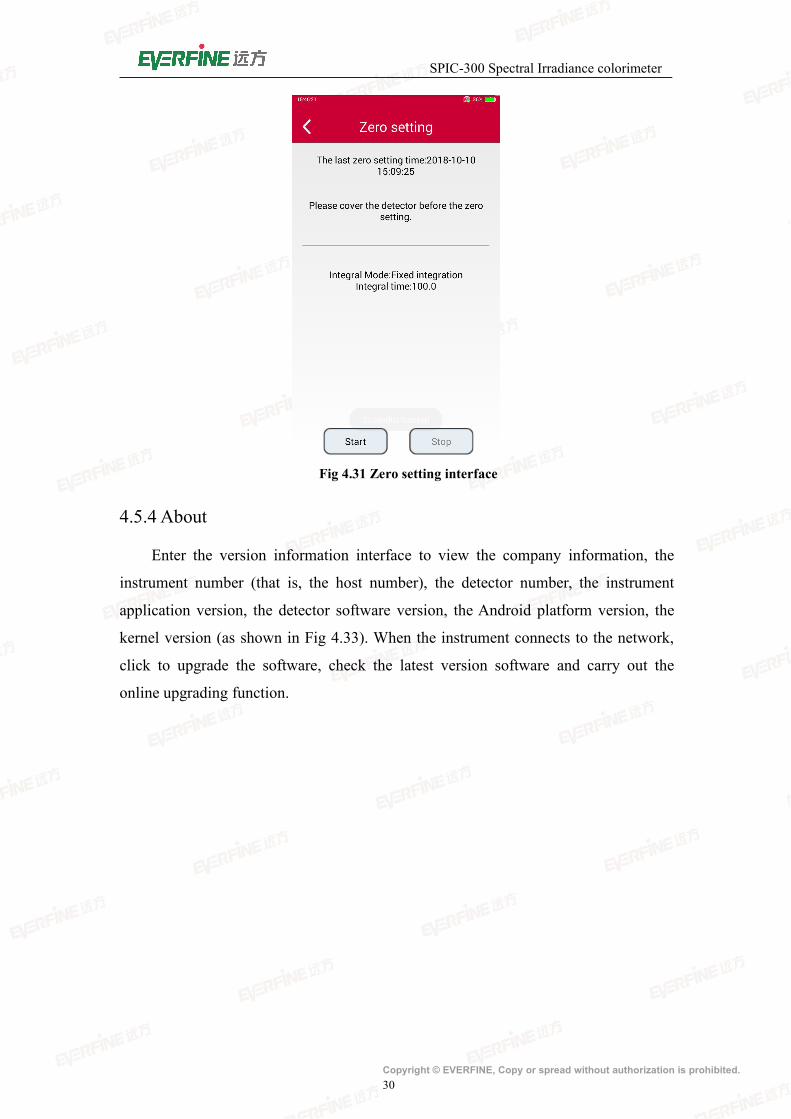
4.5.3 Zero setting
Click "Zero setting" into the zero setting interface (as shown in Fig 4.31). Before
zero calibration, cover the probe and click the "start". The progress bar in the interface
shows the progress of zero calibration. If there is a mistake in the zero process, there
will be corresponding prompt information. If you want to stop the current zeros, click
the stop button.
Special Description: in order to get higher precision, it is suggested that the
user should do the instrument zero setting before the formal measurement or
calibration. Before the zero, the equipment should be preheated for no less than 5
minutes after being opened or wake-up.
SPIC-300 Spectral Irradiance colorimeter
Copyright © EVERFINE, Copy or spread without authorization is prohibited.30
Fig 4.31 Zero setting interface
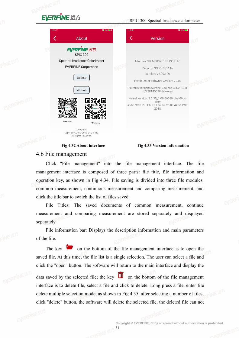
4.5.4 About
Enter the version information interface to view the company information, the
instrument number (that is, the host number), the detector number, the instrument
application version, the detector software version, the Android platform version, the
kernel version (as shown in Fig 4.33). When the instrument connects to the network,
click to upgrade the software, check the latest version software and carry out the
online upgrading function.
SPIC-300 Spectral Irradiance colorimeter
Copyright © EVERFINE, Copy or spread without authorization is prohibited.31
Fig 4.32 About interface Fig 4.33 Version information
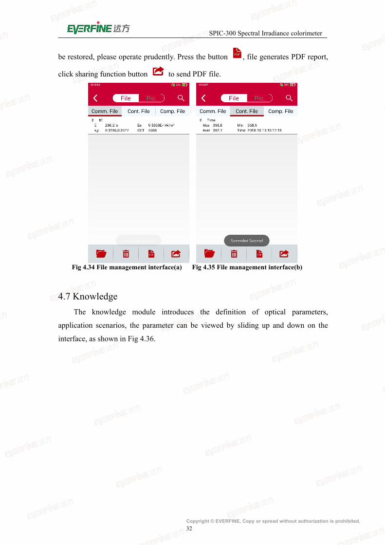
4.6 File managementClick "File management" into the file management interface. The file
management interface is composed of three parts: file title, file information and
operation key, as shown in Fig 4.34. File saving is divided into three file modules,
common measurement, continuous measurement and comparing measurement, and
click the title bar to switch the list of files saved.
File Titles: The saved documents of common measurement, continue
measurement and comparing measurement are stored separately and displayed
separately.
File information bar: Displays the description information and main parameters
of the file.
The key on the bottom of the file management interface is to open the
saved file. At this time, the file list is a single selection. The user can select a file and
click the "open" button. The software will return to the main interface and display the
data saved by the selected file; the key on the bottom of the file management
interface is to delete file, select a file and click to delete. Long press a file, enter file
delete multiple selection mode, as shown in Fig 4.35, after selecting a number of files,
click "delete" button, the software will delete the selected file, the deleted file can not
SPIC-300 Spectral Irradiance colorimeter
Copyright © EVERFINE, Copy or spread without authorization is prohibited.32
be restored, please operate prudently. Press the button , file generates PDF report,
click sharing function button to send PDF file.
Fig 4.34 File management interface(a) Fig 4.35 File management interface(b)
4.7 KnowledgeThe knowledge module introduces the definition of optical parameters,
application scenarios, the parameter can be viewed by sliding up and down on the
interface, as shown in Fig 4.36.

SPIC-300 Spectral Irradiance colorimeter
Copyright © EVERFINE, Copy or spread without authorization is prohibited.33
Fig 4.36 Knowledge interface
4.8 Spectral calibration
Fig 4.37 Spectral calibration interface
Referring to the 4.2.2 section, click the spectral calibration menu, then enter into the
calibration interface, as shown in Fig 4.37, input the correlated color temperature and
the illuminance value which is required by calibration condition, and then click the
SPIC-300 Spectral Irradiance colorimeter
Copyright © EVERFINE, Copy or spread without authorization is prohibited.34
calibration. Click “Save” to complete the spectral calibration.
Note: Before spectral calibration of the instrument, do zero setting after
warming up. Spectral calibration will directly affect the measurement accuracy,
only professionals can operate this function.
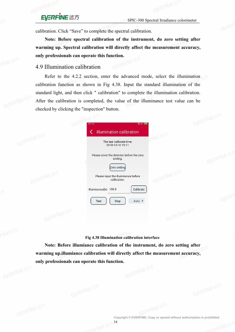
4.9 Illumination calibrationRefer to the 4.2.2 section, enter the advanced mode, select the illumination
calibration function as shown in Fig 4.38. Input the standard illumination of the
standard light, and then click " calibration" to complete the illumination calibration.
After the calibration is completed, the value of the illuminance test value can be
checked by clicking the "inspection" button.
Fig 4.38 Illumination calibration interface
Note: Before illumiance calibration of the instrument, do zero setting after
warming up.illumiance calibration will directly affect the measurement accuracy,
only professionals can operate this function.
SPIC-300 Spectral Irradiance colorimeter
Copyright © EVERFINE, Copy or spread without authorization is prohibited.35
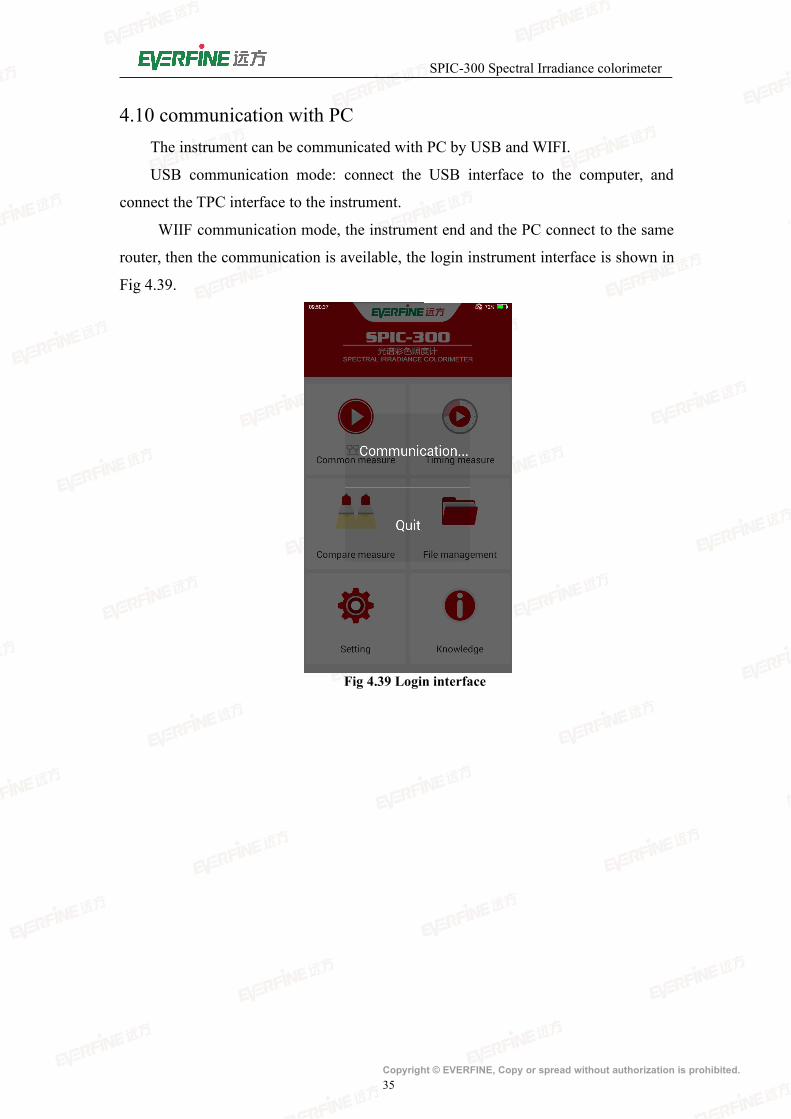
4.10 communication with PCThe instrument can be communicated with PC by USB and WIFI.
USB communication mode: connect the USB interface to the computer, and
connect the TPC interface to the instrument.
WIIF communication mode, the instrument end and the PC connect to the same
router, then the communication is aveilable, the login instrument interface is shown in
Fig 4.39.
Fig 4.39 Login interface
SPIC-300 Spectral Irradiance colorimeter
Copyright © EVERFINE, Copy or spread without authorization is prohibited.36
Chapter 5 PC Software InstructionSPICSuite is equipped with PC software. User can download data from the
software by USB or WIFI connection and a number of instruments can be set up for
network communication and measurement.
The USB cable should be correctly connected or wireless router should be set if
user needs remote control of SPIC-300 by PC.
5.1 PC software installationRemote control soft is equipped with the device.
Note: please check the serial number consistency between the software and
the device before installation. If it is not, please contact EVERFINE immediately,
otherwise the accuracy will not be guaranteed.
5.1.1 Operating system demands
1 Windows XP or updated versions;
2 200 MB or more free space;
3 ACD-ROM driver (only needed for the installation);
4 One USB 2.0 connection port;
5 Display resolution: 1280×1024 or more; 1280×1024 recommended.
5.1.2 Software installation
1 Please find the naming rules for this software in the file “ReadMe”;
2 Open SPICSuite installation folder;
3 Under the naming rules, click the corresponding catalog of
SPICSuite_V2.00.XXX (XXX is version number)
4 Double-click Setup.exe ,finish the installation
following the procedures.
5.2 Software Overview
5.2.1 Software start
Click “Start Menu”, and then find “EVERFINE” in “Programs”. Click the
icon“SPICSuite_ V2.00.XXX” to start the software.
SPIC-300 Spectral Irradiance colorimeter
Copyright © EVERFINE, Copy or spread without authorization is prohibited.37
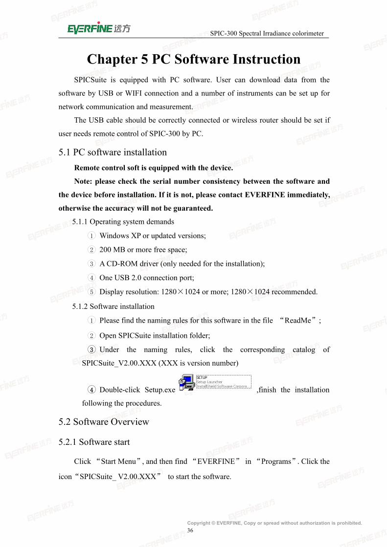
5.2.2 Main interface introduction
The main interface of SPICSuite software is shown in Fig 5.1.1.
Fig 5.1.1 Main operation interface
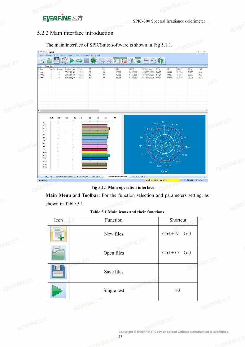
Main Menu and Toolbar: For the function selection and parameters setting, as
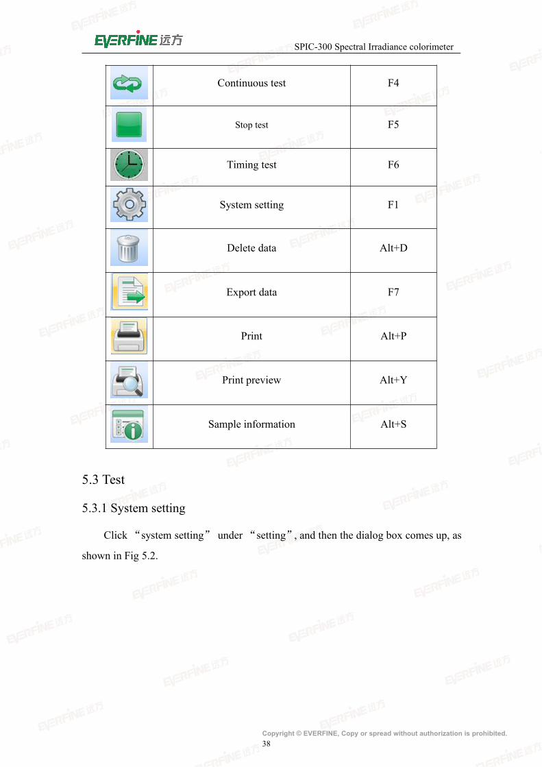
shown in Table 5.1.Table 5.1 Main icons and their functions
Icon Function Shortcut
New files Ctrl + N (n)
Open files Ctrl + O (o)
Save files
Single test F3
SPIC-300 Spectral Irradiance colorimeter
Copyright © EVERFINE, Copy or spread without authorization is prohibited.38
Continuous test F4
Stop test F5
Timing test F6
System setting F1
Delete data Alt+D
Export data F7
Print Alt+P
Print preview Alt+Y
Sample information Alt+S
5.3 Test
5.3.1 System setting
Click“system setting” under “setting”, and then the dialog box comes up, as
shown in Fig 5.2.

SPIC-300 Spectral Irradiance colorimeter
Copyright © EVERFINE, Copy or spread without authorization is prohibited.39
Fig 5.2 Interface of system settings
Communication mode: Select USB communication or WIFI communication(the
equipment need to support WIFI function);
USB communication:Click “Add” button first, then click “Login” to connect to
the instrument;
WIFI communication:Click “Search” button first, then click “Login” to connect
to the instrument.
When the state displays “Login”, it can start testing.
Port : if WIFI communication is selected, please set up network port number,
whose default is 5000;
IP: if WIFI communication is selected, please directly click the search function to
identify all the instruments connected to the PC terminal and display them in the
list.;

SPIC-300 Spectral Irradiance colorimeter
Copyright © EVERFINE, Copy or spread without authorization is prohibited.40
Integration mode:Automatic integration and fixed integration;
Automatic integration: when testing, the instrument automatically selects the
appropriate integration time according to the intensity of the light signal.
Fixed integration: the user sets the integration time according to the intensity of
the measured light signal.
Time interval for the continuous test: the time interval between every two single
tests in the continuous mode;
Average times: set the average number of tests, the software will automatically
calculate the average after many tests as the current measurement results.
Sensitivity: set the sensitivity gear used in the test.
AC/DC mode: DC/AC:50Hz , AC:60Hz.
5.3.2 Test
User can start the test accordingly as long as the corresponding setting is
completed.
Click “single test” under “test” or “ ” or press shortcut F3, and then the
device starts single test.
Click “continuous test” under “test”or “ ”or press shortcut F4, and then
the device starts continuous test. Click “ ” or press shortcut F5, and then the device
stops continuous test. (Attention: under continuous test, click "Cancel" can also stop
the test).
The dialog box of test information will come up automatically after each single
test. User can easily edit the information. If user need to modify the information after
continuous test, please double click the current test data and the system will pop up
the dialog box.
5.3.3 Type diagram
Type diagram includes: chromaticity diagram, SDCM and white light binning,
spectrum, color rendering index , respectively as shown in Fig 5.3, 5.4, 5.5, 5.6.
CIE1931, CIE1960, CIE1976 chromaticity diagram are available by the
drop-down menu;
SDCM can be automatically judged and calculated the results according to the
color coordinates. Right-click the to edit SDCM data; white light binning is based on

SPIC-300 Spectral Irradiance colorimeter
Copyright © EVERFINE, Copy or spread without authorization is prohibited.41
the color coordinates to judge the region , then to achieve classification. User can edit
in the white binning menu;
Choose absolute or relative spectral spectrum as appropriate;
CRI diagrams are divided into histogram and radar, which reflect the CRI more
directly.
Fig 5.3 Chromaticity diagram1931(left)Chromaticity diagram1976(right)
Fig 5.4 SDCM(left)white light binning(right)
Fig 5.5 Spectrum diagram

SPIC-300 Spectral Irradiance colorimeter
Copyright © EVERFINE, Copy or spread without authorization is prohibited.42
Fig 5.6 CRI histogram(left)radar diagram(right)
Fig 5.7 Spectral superposition diagram
Fig 5.8 Time test curve
5.3.4Test information Modification
User can modify the test information after one single test or when all tests are
finished.
Click “sample information” under “data management” or double click the
specific data on the data list, and then the dialog box“sample information”comes up,
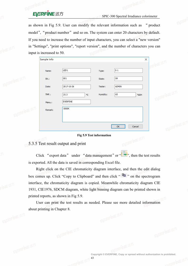
SPIC-300 Spectral Irradiance colorimeter
Copyright © EVERFINE, Copy or spread without authorization is prohibited.43
as shown in Fig 5.9. User can modify the relevant information such as “product
model”,“product number”and so on. The system can enter 20 characters by default.
If you need to increase the number of input characters, you can select a "new version"
in "Settings", "print options", "report version", and the number of characters you can
input is increased to 50.
Fig 5.9 Test information
5.3.5 Test result output and print
Click “export data” under “data management”or “ ”, then the test results
is exported. All the data is saved in corresponding Excel file.
Right click on the CIE chromaticity diagram interface, and then the edit dialog
box comes up. Click “Copy to Clipboard” and then click “ ” on the spectrogram
interface, the chromaticity diagram is copied. Meanwhile chromaticity diagram CIE
1931, CIE1976, SDCM diagram, white light binning diagram can be printed shown in
printed reports, as shown in Fig 5.9.
User can print the test results as needed. Please see more detailed information
about printing in Chapter 8.

SPIC-300 Spectral Irradiance colorimeter
Copyright © EVERFINE, Copy or spread without authorization is prohibited.44
Fig 5.9 打 Print option
SPIC-300 Spectral Irradiance colorimeter
Copyright © EVERFINE, Copy or spread without authorization is prohibited.45
Chapter 6 Instrument VerificationThis method is applicable to the verification of the specifications of SPIC-300
spectral irradiance colorimeter.
Besides specification, the instrument do zero setting after turned on or in
standby wake no less than five minutes to warm up, than test after the
calibration .
6.1 Verification conditions
6.1.1 Working conditions
(1) Ambient temperature: 23°C±1°C;
(2) Relative room humidity:55%RH ± 5%RH;
(3) Indoors without corrosive atmosphere and ensure electromagnetic
environment does not interfere with the test results.
6.1.2 Apparatus
Mercury lamp, Thermostatic blue LED lamp, Standard illuminant A, Standard
power supply, Optical rail
6.2 Items and methods
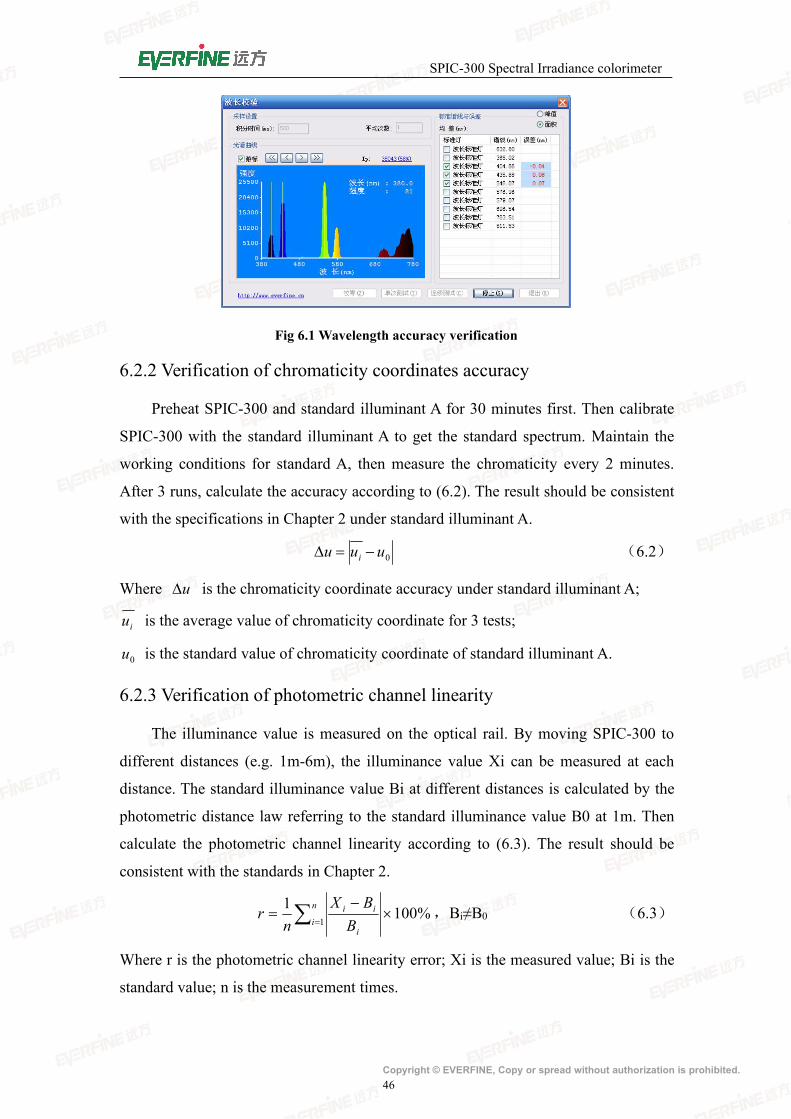
6.2.1 Verification of wavelength accuracy
Choose a mercury lamp or laser as the light source, test three times at the spectra
line 404.66nm, 435.88nm, 546.07nm and 632.80nm, then figure out each peak
wavelength λi. Then calculate according to formula 6.1, the deviation should meet the
technical specifications of wavelength accuracy shown in Chapter 2.
0 i (6.1)
Where is the wavelength accuracy, nm;
i is the wavelength average value of three tests;
0 is characteristic wavelength corresponding to the peak value of the
mercury lamp.
SPIC-300 Spectral Irradiance colorimeter
Copyright © EVERFINE, Copy or spread without authorization is prohibited.46
Fig 6.1 Wavelength accuracy verification
6.2.2 Verification of chromaticity coordinates accuracy
Preheat SPIC-300 and standard illuminant A for 30 minutes first. Then calibrate
SPIC-300 with the standard illuminant A to get the standard spectrum. Maintain the
working conditions for standard A, then measure the chromaticity every 2 minutes.
After 3 runs, calculate the accuracy according to (6.2). The result should be consistent
with the specifications in Chapter 2 under standard illuminant A.
0uuu i (6.2)
Where u is the chromaticity coordinate accuracy under standard illuminant A;
iu is the average value of chromaticity coordinate for 3 tests;
0u is the standard value of chromaticity coordinate of standard illuminant A.
6.2.3 Verification of photometric channel linearity
The illuminance value is measured on the optical rail. By moving SPIC-300 to
different distances (e.g. 1m-6m), the illuminance value Xi can be measured at each
distance. The standard illuminance value Bi at different distances is calculated by the
photometric distance law referring to the standard illuminance value B0 at 1m. Then
calculate the photometric channel linearity according to (6.3). The result should be
consistent with the standards in Chapter 2.
%10011
n
ii
ii
BBX
nr ,Bi≠B0 (6.3)
Where r is the photometric channel linearity error; Xi is the measured value; Bi is the
standard value; n is the measurement times.

SPIC-300 Spectral Irradiance colorimeter
Copyright © EVERFINE, Copy or spread without authorization is prohibited.47
6.2.4 Verification of stray light
With the standard illuminant A as the light source, set up the sensitivity to“low”
and choose 450nm as the working wavelength. After zero calibration, take down the
peak value AD0(AD0>55000)and calculate the average value after 10 runs. Put an
optical filter whose cutoff wavelength at 510nm on the incident light path, and take
down the average value AD' around 450±5nm. Then calculate the percentage of stray
light according to (6.4).
SL=AD'/AD0×100% (6.4)
Where SL is the percentage of stray light; AD0 is the peak value of spectrum;
AD' is the value at chosen wavelength (around the range of cutoff wavelengths).

SPIC-300 Spectral Irradiance colorimeter
Copyright © EVERFINE, Copy or spread without authorization is prohibited.48
Chapter 7 Common FaultsCommon Faults
1. It prompt that the USB device can not be recognized, when the SPIC300
connects with computer by USB .
Solutions:
a. Check whether the USB port of the computer is OK. User can check it by
USB device. If it also can not be recognized, please change a USB port of the
computer.
b. Check the USB communication cable, and make sure the USB
communication cable is well. Change a USB cable or wire other USB device
with this cable.
2. The spectrum signal is weak or it can not be test.
Solutions:
a. Check whether it is in a right way when testing the dark current. And please
do zero calibration again, refering to the section 4.2.3.
3. Communication failed.
Solutions:
check if the power switch on the side of the detector is off, press it to switch on.
4. Measurement failed through the blue tooth
Solutions:
a. Remove the obstacle between the main unit and the cell phone, or shorten the
distance of them to ensure the blue tooth signal unimpeded
b. Click the “Bluetooth ini” under the menu “System Setting”, rematch the
main unit and the detector, refer to section 4.2.4 for details.
c. The power of the detector is low(the indicator is off or the orange light is
flashed), and please connect it with the main unit and charge it with the power.
5. Measurement failed through theWIFI communication.
Solutions:
a. Exit the remote mode, and reconnect the WIFI.
b. Reconnect the WIFI after the test is finished on the main interface.
SPIC-300 Spectral Irradiance colorimeter
Copyright © EVERFINE, Copy or spread without authorization is prohibited.49
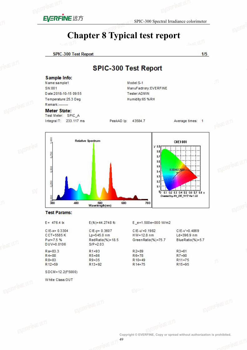
Chapter 8 Typical test report