Embed Size (px)
Citation preview

SPH Study of High Speed Ship Slamming
Daniel J. Veen and Tim P. Gourlay Centre for Marine Science and Technology
Curtin University of Technology Perth, Western Australia
Email: [email protected]
Abstract — A preliminary investigation of wet-deck slamming of high speed multi-hull ships using Smoothed Particle Hydrodynamics (SPH) is discussed. The SPH algorithm is applied to the two-dimensional dam beak test case for the purposes of validation and the results compared with published experimental and SPH data. Validation of water sitting in a Tank is also presented, along with preliminary results for a two-dimensional wedge entering a free surface.
I. INTRODUCTION
Numerical modelling of large floating objects in rough seas has met with limited success using available techniques in Computational Fluid Dynamics (CFD) particularly when wave impacts are involved. An understanding of the sea loads on high speed multi-hull ships is essential to ensuring the structural design criteria are met and assessing the fatigue life of the structure [1]. In particular, high speed catamarans and trimarans are prone to wet deck slam events, where the relative vertical motion of the water surface and ship bow causes water to impact the wet deck. Such events subject the wet deck to high localised pressure in the region of impact and also induce hull vibrations, commonly known as whipping, which can place significant global loads on the structure.
The current research aims to use Smoothed Particle Hydrodynamics (SPH) to model the impact of sea water on various hull shapes examined experimentally in [2] using an SPH algorithm written in Matlab®.
II. SPH METHODOLOGY
The following SPH methods have been used during the validation and preliminary slamming investigation:
• The momentum equation due to [3].
• The differential equation for continuity as quoted by [3].
• The Cubic Spline Kernel described by [3].
• The equation of state according to [4].
• The artificial viscosity described by [3] with α = 0.01 and β = 0.
• The particles were moved using the XSPH variant according to [3] with ε = 0.5 and a modified Kernel.
• Reinitialisation of the density field described by [5].
• The Lennard-Jones boundary method quoted by [3].
• The predictor-corrector time stepping method [6].
• A fixed time step at 80% of the Courant-Friedrichs-Levy condition limit and a fixed smoothing length based on the initial particle separation [7].
III. MODEL VALIDATION
The initial stages of the project required the validation of the SPH method in two dimensions. The two-dimensional dam break was chosen as the most suitable validation case and the results compared against the experimental data of [8] and the SPH results produced by [5] and [6].
Figure 1. Schematic of the two-dimensional dam break.
3rd ERCOFTAC SPHERIC workshop on SPH applications June 4th-6th 2008, Lausanne, Switzerland
Page 2 of 4
Fig. 1 illustrates the first validation test case, where L is equal to H and W is 5.4H (for simplicity, H was set to 1m). The fluid, consisting of 8100 particles arranged on a Cartesian grid, was allowed to fall under the influence of gravity within the confines of the artificial boundaries. At regular intervals the position of the surge front, taken from the particle with the maximum x position, was plotted against time and the result compared to both experimental [8] and published SPH [5] data (Fig. 2). The results show very little difference between the two sets of SPH data, however, the experimental data is characterised by a slower surge front velocity. This could be due to many factors including a non-uniform initial breaking of the dam and viscous effects slowing the bore front, which are not accounted for in the current SPH methodology.
The form of the breaking dam and the pressure field were also analysed in detail. Here L was set to 2H in order to be in line with the SPH data published in [5] and the number of particles was reduced slightly to 7200. The overall form at each time instant was very similar to those depicted in [5]. Through the entire duration of the simulation, particles that were far from impact zones were well ordered and had a pressure which was near hydrostatic for their depth (fig. 3).
The maximum run-up height for this particular model should, according to [9], be approximately 2.0m and by studying the data and associated images in fig. 3 it has been shown that the maximum wall run up is slightly less than this 2.0m target. The greater theoretical run-up height is in part due to the maximum surge front velocity (6.3m/s), calculated from V=2(gH)1/2 [9], being greater than the maximum 5.3 m/s calculated from the gradient of the SPH data in fig. 2.
Figure 2. Surge front position with time
Figure 3. Dam break evolution at (a) 0.48s, (b) 1.40s and (c) 2.10s.
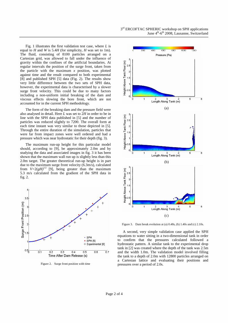
A second, very simple validation case applied the SPH equations to water sitting in a two-dimensional tank in order to confirm that the pressures calculated followed a hydrostatic pattern. A similar tank to the experimental drop tank in [2] was created where the depth of the tank was 2.5m and the width 1.0m. The validation model involved filling the tank to a depth of 2.0m with 12800 particles arranged on a Cartesian lattice and evaluating their positions and pressures over a period of 2.0s.
(b)
(c)
(a)
3rd ERCOFTAC SPHERIC workshop on SPH applications June 4th-6th 2008, Lausanne, Switzerland
Page 3 of 4
Figure 4. Tank Validation Model after 1.5s with h = 1.2∆x
The tank validation case proved to be more difficult than expected. The original smoothing length, h, was set to 1.6 ∆x (where ∆x is the initial spacing between the centre of neighbouring particles) under the premise that more particles contained within the compact support would improve stability in the final solution. However, this allowed neighbouring particles to move towards each other and occasionally occupy the same space, despite the presence of the artificial viscosity and XSPH corrections.
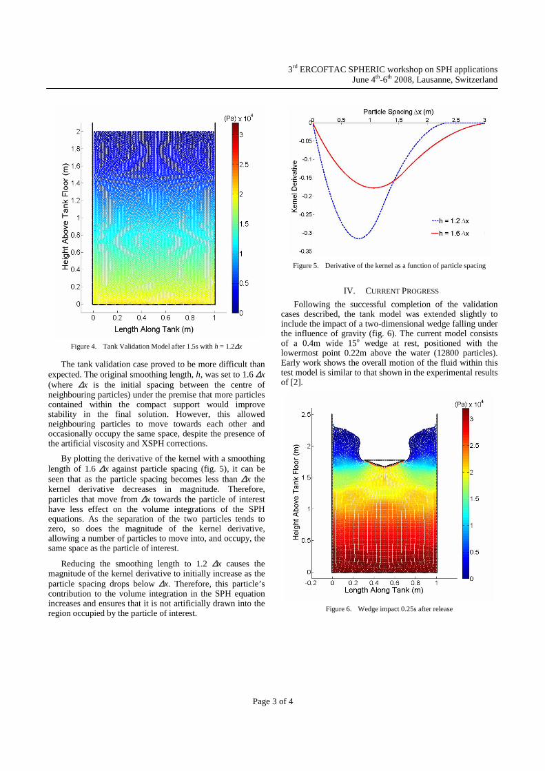
By plotting the derivative of the kernel with a smoothing length of 1.6 ∆x against particle spacing (fig. 5), it can be seen that as the particle spacing becomes less than ∆x the kernel derivative decreases in magnitude. Therefore, particles that move from ∆x towards the particle of interest have less effect on the volume integrations of the SPH equations. As the separation of the two particles tends to zero, so does the magnitude of the kernel derivative, allowing a number of particles to move into, and occupy, the same space as the particle of interest.
Reducing the smoothing length to 1.2 ∆x causes the magnitude of the kernel derivative to initially increase as the particle spacing drops below ∆x. Therefore, this particle’s contribution to the volume integration in the SPH equation increases and ensures that it is not artificially drawn into the region occupied by the particle of interest.
Figure 5. Derivative of the kernel as a function of particle spacing
IV. CURRENT PROGRESS
Following the successful completion of the validation cases described, the tank model was extended slightly to include the impact of a two-dimensional wedge falling under the influence of gravity (fig. 6). The current model consists of a 0.4m wide 15o wedge at rest, positioned with the lowermost point 0.22m above the water (12800 particles). Early work shows the overall motion of the fluid within this test model is similar to that shown in the experimental results of [2].
Figure 6. Wedge impact 0.25s after release

3rd ERCOFTAC SPHERIC workshop on SPH applications June 4th-6th 2008, Lausanne, Switzerland
Page 4 of 4
An analysis of the calculated forces and a possible extension to include the quasi fluid particle method outlined in [10] will be completed before replicating the original hull drop tests detailed in [2]. The quasi fluid particle method will enable the hull cross sections to interact with the fluid through the SPH equations without changing their geometry, unless otherwise specified.
V. CONCLUSIONS
The present SPH methods have been examined and validated against a two-dimensional dam break. Results have shown that the simulated surge front position matches the data contained in literature, and the run up height is similar to that expected from theory. The SPH equations were also applied to water sitting in a tank and a hydrostatic pressure field was maintained. The validation cases completed have now enabled work to begin on modelling wedge water entries and hull slamming.
Figure 7. Sample hull shapes
VI. FUTURE WORK
In the coming months the current SPH model will be extended to allow larger numbers of particles in larger volumes to be modelled and the experimental drop tests of various hull shapes examined in [2] will be replicated. Examples of two of the proposed shapes are given in fig. 7 including a 25o wedge with side plates (top) and a symmetric hull with a rounded voluminous centre bow (bottom). Air will then be introduced in order to create a coupled algorithm to simulate venting and entrainment in the arches and corners of the test models.
The SPH model will ultimately be extended to three dimensions and applied to the aforementioned validation cases and finally to the experimental tests conducted in [2]. The result will be a SPH algorithm that can be applied to a variety of hull shapes in both two and three dimensions.
REFERENCES [1] G. A. Thomas, M. R. Davis, D. S. Holloway, N. L. Watson, and T. J.
Roberts, “Slamming response of a large high-speed wave-piercer catamaran,” Marine Technology, vol. 40, No. 2, pp. 126-140, April 2003.
[2] M. R. Davis, J. R. Whelan, “Computation of wet deck bow slam loads for catamaran arched cross sections,” Ocean Engineering, vol. 34, pp. 2265-2276, 2007.
[3] J. J. Monaghan, “Simulating free surface flows with SPH,” J. Computational Physics, vol. 110, pp. 399-406, 1994.
[4] G. K. Batchelor, “An introduction to fluid dynamics,” Cambridge Univ. Presss, Cambridge, U.K., 1973.
[5] A. Colagrossi, M. Landrini, “Numerical simulation of interfacial flows by smoothed particle hydrodynamics,” J. Computational Physics, vol. 191, pp. 448-475, 2003.
[6] D. A. Jones, D., Belton, “Smoothed particle hydrodynamics: applications within DSTO,” Defence Science and Technology Organisation, Victoria, Australia, 2006.
[7] G. R. Liu, M. B. Liu, “Smoothed particle hydrodynamics – a mesh-free particle method,” World Scientific Publishing, Singapore, 2003.
[8] J. C. Martin, W. J. Moyce, “An experimental study of the collapse of liquid columns on a rigid horizontal plane,” Phil. Trans. Roy. Soc. London, vol. 244, No. 882, pp. 312-324, 1952.
[9] V. L. Streeter, E. B. Wylie, K. W. Bedford, “Fluid mechanics. 9th ed.” McGraw Hill, USA, 1998.
[10] M. Gomez-Gesteira, D. Cerqueiro, C. Crespo, R. A. Dalrymple, “Green water overtopping analyzed with a SPH model,” Ocean Engineering, vol. 32, pp. 223-238, 2005.