Embed Size (px)
Citation preview

International Journal of Computer Applications (0975 – 8887)
Volume 151 – No.7, October 2016
36
Speed Control of Induction Motor using PI and V/F
Scalar Vector Controllers
Hanan Mikhael D. Habbi Electrical engineering
department University of Baghdad
Hussein Jalil Ajeel Electrical engineering
department University of Technology
Inaam Ibrahim Ali Electrical engineering
department University of Technology
ABSTRACT
In this paper, Induction Motors (IM) are widely used in the
industrial application due to a high power/weight ratio, high
reliability and low cost. A Space Vector PWM (SVPWM) is
utilized for PWM controlling scheme. The performance of
both the speed and torque is promoted by a modified PI
controller and V/F scalar control. A scalar control is a simple
method and it's operated to control the magnitude of the
control quantities in constant speed application. V/F scalar
control has been implemented and compared with the PI
controller. The simulation results showed that Indirect Field
oriented control (IFOC) induction motor drive employ
decoupling of the stator current components which produces
torque and flux. The complete mathematical model of the
system is described and simulated in MATLAB/SIMULINK.
The simulation results provides a smooth speed response and
high performance under various dynamic operations.
Keywords
Induction motor, SVPWM, PI-Controller, V/F
ABBREVIATIONS , : the d and q axis components of the stator current
q : the d and q axis component of the rotor current
ℷ , ℷ : the d and q axis components of the stator fluxes
ℷ , ℷ : the d and q axis components of the rotor fluxes , : the d and q axis components of the stator voltage.
s, R : the stator and rotor resistances.
r: the rotor speed
P: the number of pole pairs
N the number of turns
ℷs the magnetic flux-linkage in the stator
Air gap flux-linkage
K the constant of coil
The induced voltage in the stator,
m: the total motor and load inertia
TL, b: the load torque and the friction Coefficient.
: the stator inductances.
r: the rotor inductances.
Lm: the mutual Inductance.
1. INTRODUCTION Three phase induction motors are the most widely used for
industrial control and automation. They are often called the
workhorse of the motion industries due to their robustness,
reliability, less maintenance and of high durability [1].
Control Techniques of Induction Motor (IM) are Variable
frequency control techniques of IM can be divided into two
major types: scalar control, vector control methods. Scalar
control or as it is called V/F control. The structure is very
simple and it is normally used without speed feedback.
However, this controller doesn’t achieve a good accuracy in
both speed and torque responses, mainly due to the fact that
the stator flux and the torque are not directly controlled [3].
The main objective of this control method is, as in separately
exited DC machines, to independently control the torque and
flux; this is done by choosing a d-q rotating reference frame
synchronously with the rotor flux space vector [4]. A voltage
source inverter (VSI) should have a stiff voltage source at the
input, that is, its Thevenin impedance should ideally be zero.
Thus, a large capacitor can be connected at the input if the
voltage source is not stiff. (VSI) consist of power bridge
devices with three output legs, each consisting of two power
switches and two freewheeling diodes, the inverter is supplied
from DC voltage source (either battery or diode-based bridge
rectifier) via LC or C filter [5]. The Space Vector Pulse Width
Modulation (SVPWM) method is an advanced, computation-
intensive PWM method and possibly the best among all the
PWM techniques for variable frequency drive application. It
exhibits the feature of good dc-bus voltage utilization and
Low total harmonic distortion (THD) compared to other
PWM methods. SVPWM is more suitable for digital
implementation and can increase the obtainable maximum
output voltage with maximum line voltage approaching 70.7%
of the DC link voltage in the linear modulation range [6].
SVPWM is adopted in this paper for PWM controlling
scheme. In addition, a comparative study of the speed control
of induction motor using V/F scalar vector and PI controllers
is illustrated. The induction motor drive can be controlled to
obtain better performance by many methods as scalar
controller (V/F) and vector controller (Field oriented control
and direct torque control) by using PI, intelligent controller,
etc. In this section, a historical review of previous studies
related to controlling the induction motor controller is
introduced. Pabitra Kumar Behera et.al, 2014[7] presents a
design and implementation of scalar control of induction
motor. This method leads to be able to adjust the speed of the
motor by control the frequency and amplitude of the stator
voltage of induction motor, the ratio of V/F is constant. It is
also presents a comparative study of open loop and close loop
V/F control induction motor. The V/F control is based on
advent of stator voltage derivatives. From experiment and
results we shown that the closed loop V/F control gives better
response and better result as compared to open loop V/F
control of induction motor. Jay R. Patel, S.R. Vyas, 2014[1]
proposed a Variable Voltage-Variable Frequency (V/F) base
torque-speed control of three phase induction motor fed by a
PWM Voltage Source Inverter will be simulated. The PWM
method, which involves the modulation of conventional
sinusoidal reference signal and a triangular carrier to produce
pulse width modulated output signals, which are applied to

International Journal of Computer Applications (0975 – 8887)
Volume 151 – No.7, October 2016
37
Power Electronic Switches of a 2-Level Voltage Source
Inverter, driving a Three Phase Induction Motor, shall be
used. The performance analysis of three phase induction
motor fed by PWM voltage source inverter in terms of phase
current of inverter, rotor and stator current, speed, and
electromagnetic torque developed of inverter is simulated.
Simulation results illustrate the performance and effectiveness
of constant V/F Induction Motor drive. The actual speed
follows the reference speed and change in the speed from high
to low and low to high makes change in the voltage and
current profile accordingly. Devraj Jee, Nikhar Patel, 2013[8]
presents the need of Speed Control in Induction Motors. V/F
Control has proven to be the most versatile. The overall
scheme of implementing V/F control has been presented. One
of the basic requirements of this scheme is the PWM Inverter.
In this, PWM Inverters have been modeled and their outputs
fed to the Induction Motor drives. The uncontrolled transient
and steady state response of the induction motor has been
obtained and analyzed. A MATLAB code was developed to
successfully implement open loop V/F Control on a PWM-
Inverter fed 3-phase Induction Motor, and the Torque was
found to be constant for various rotor speeds. It was observed
that using a Closed-Loop scheme with a Proportional
Controller gave a very superior way of controlling the speed
of an Induction motor while maintaining a constant maximum
torque. Riya Elizabeth Jose, Maheswaran K., 2015 [9]
proposed the V/F ratio that kept constant which in turn
maintains the magnetizing flux constant so that the maximum
torque remains unchanged .Z- Source inverter overcomes the
shoot through short circuit problem of VSI. But ZSI has
certain disadvantages which were overcome by switched
boost inverter to modified pulse width modulation technique
switched boost inverter (SBI) to drive a three phase induction
motor. It is often required to control the output voltage of
inverter for the constant voltage/frequency (V/F) control of an
induction Motor. PWM (Pulse Width Modulation) based
firing of inverter provides the best constant V/F control of an
induction Motor. Amongst the various PWM techniques, the
sinusoidal PWM is good enough and most popular that
provides Smooth changeover of V/F, four quadrant operation,
harmonic elimination, in both closed and open loop
applications. G. KOHLRUSZ, D. FODOR, 2011[10] there are
two control methods are compared: scalar control and vector
control, both control methods have advantages and
disadvantages. Scalar control is a cheap, well-implementable
method. Because of these advantages and its simplicity, many
applications operate with this control technique in the
industry. On the other hand, it is not satisfactory for the
control of drives with dynamic behavior, since it gives slow
response to transients. This is because the V/f Constant
method controls the magnitude of voltages and frequency
instead of controlling the phase and magnitude of currents. It
is a low-performance, but stable control technique. The field
oriented control method controls the currents so it operates
with fast responses. This method satisfies the requirements of
dynamic drives, where fast response is necessary. It is an
excellent control method to handle transients. Its disadvantage
is complexity, and the high price of the driver circuit.
Nevertheless, it is a high-performance control technique. Both
techniques are applicable over the nominal speed at the
expense of torque
2. MATHEMATICAL MODEL OF
INDUCTION MOTOR The dynamic model of induction motor can be developed by
writing differential equations for voltage and torque. For
Dynamic analysis, poly phase windings are transformed into
two phase windings (q-d) quantities [10]. The following
equivalent circuit in Fig. (1) Is used to simulate a three-phase,
P-pole, symmetrical induction motor in the dq reference
frame.
Vqs
RsLIs=Ls-Lr LIr=Lr-Lm
Rr
ℷ
r ℷ r
ℷq ℷqrLm
IqrIqsAC
(a) q-circuit
Vds
RsLIs=Ls-Lr LIr=Lr-Lm
Rr
ℷ
r ℷqr
ℷd ℷdrLm
IdrIdsAC
(b) d-circuit
-
+
Figure (1) induction motor equivalent circuit a) qs circuit
and b) ds circuit [11]
The dynamic machine model in stationary frame can be
derived simply by substituting ωe=0. The corresponding
stationary frame equations are given as
……….……. (1)
………... . (2)
ℷ ….…….. (3)
ℷ ………….…. (4)
Where = =0.
The fluxes are combined with the currents according to the
following expressions
….. (5)
…. (6)
… (7)
… (8)
The development of torque is by the interaction of air gap flux
and rotor current [11] and [12]. Therefore, the torque can be
generally expressed in the vector form as:
…………………………..… (9)
- = (
J
………………… ……………... (10)
) ………………..... (11)

International Journal of Computer Applications (0975 – 8887)
Volume 151 – No.7, October 2016
38
3. SIMULATION OF INDUCTION
MOTOR The inputs of a squirrel cage induction machine are the three-
phase voltages, their fundamental frequency, and the load
torque. The outputs, on the other hand, are the three phase
currents, the electrical torque, and the rotor speed, the
induction machine model will have blocks transforming the
three-phase voltages to the d-q frame and the d-q currents back
to three-phase[12]. The block ( to ) transforms three
phase voltage into two phase stationary reference frame
voltages . The simulation of the IM mathematical model is
shown in Fig. (2), which consists of the main blocks: abc to dq
block, D-axis circuit block, Q-axis circuit block, dq to abc
current block, speed determination block and the torque
determination block.
Figure (2) IM dynamic model Simulink circuit
To transfer the 2-axis stationary current frame ( ) to three-
phase stationary current frame ( ), using inverse
transformation equation (12) [12].
=
…………..… (12)
4. SPEED CONTROLLER In this section, two types of controllers were used, to enhance
the FOC and scalar vector system for controlling the speed of
IM, these controllers are:
1. V/F constant
2. Conventional PI controller (trial and error tuning)
4.1 Scalar Control (V/F) V/F is the most common speed control of an induction motor.
The torque developed by the induction motor is directly
proportional to the V/F ratio. The voltage and frequency are
tried to vary, keeping their ratio constant, then the torque
produced by induction motor will remain constant for all the
speed range [14]. In addition, V/F is the simplest controller. It
assumes a constant relation between voltage and frequency
and it is normally used without speed feedback. However, this
controller doesn’t achieve a good accuracy in both speed and
torque responses, mainly due to the fact that the stator flux
and the torque are not directly controlled [4]. The scalar
control method is based on varying two parameters
simultaneously. The speed can be varied by increasing or
decreasing the supply frequency, but this results in change of
impedances. The change of impedances eventuates the
increase or decrease of current. If the current is small, the
torque of motor decreases. If the frequency decreases or the
voltage increases, the coils can be burned or saturation can
occur in the iron of coils. To avoid these problems, it is
necessary to vary the frequency and the voltage at the same
time. In this way, the occurring disadvantages of changing
frequency and voltage can be compensated. According to the
equation of induced voltage the V/Hz constant control gives
constant flux in the stator (Eq. 13).
ℷ ……………… (13)
The torque–speed equation of induction motors (Eq. 14) can
be used to determine the voltage–torque
………………. (14)
4.1.1 Closed Loop V/F Control The basis of constant V/F speed control of induction motor is
to apply a variable magnitude and variable frequency voltage
to the motor (Fig. (3)). both the voltage source inverter and
current source inverters are used in adjustable speed ac drives.
The following block diagram shows the closed loop V/F
control using a VSI.
Fig. (3) Closed-loop V/Hz constant control
The closed-loop method offers a more precise solution to
controlling the speed than the open-loop method.
Furthermore, the closed-loop technique controls the torque,
too. A major disadvantage of the open-loop control method is
that this technique does not control the torque, so the desired
torque is only accessible at the nominal operating point. If the
load torque changes, the speed of the motor will change [7,
14].
4.1.2 Open loop V/F control The open loop V/F control of an induction motor is the most
common method of speed control because of its simplicity
and these types of motors are widely used in industry. This
type of motor control has some advantages are low cost,
simplicity and immunity to errors of feedback signals
.Traditionally, induction motors have been used with open
loop 50Hz power supplies for constant speed applications. For
adjustable speed drive applications, frequency control is
natural, however, voltage is required to be proportional to
frequency so that the stator flux remains constant ℷ
remains constant [7]. Block diagram of the open loop V/F
control for an IM as shown in Fig. (4).

International Journal of Computer Applications (0975 – 8887)
Volume 151 – No.7, October 2016
39
Fig (14) open loop constant V/F speed control [14]
Some problems encountered in the operation of this open loop
drive ,these problem are The speed of the motor cannot be
controlled , because the rotor speed will be slightly less than
the synchronous speed and that in this scheme the stator
frequency and hence the synchronous speed is the only
control variable. The effect of the above can make the stator
currents exceed the rated current by a large amount. Then the
slip speed cannot be maintained, due to the difference
between the synchronous speed and the electrical rotor speed
[7].
4.2 Vector Controllers The field oriented control is one of the most prevalent control
methods that are utilized to improve the dynamic performance
of a three-phase induction because the FOC manner includes
making the induction motor behave similar to a DC motor.
The FOC is good and robust control in transient and it is
based on mathematical abstraction .stator currents of the
induction machine are separated into flux-and torque
producing components by utilizing transformation to the d-q
coordinate system, whose direct axis (d) is aligned with the
rotor flux space vector. It means that the q-axis component of
the rotor flux space vector is always zero [14, 15].
ℷ , ℷ ℷ
The speed error, with the help of a Conventional PI controller,
is converted into a torque controlling current
Component , of the stator current. This current
component is used to regulate the torque along with the slip
speed. The control equation which The PI controller involves
is given as
…………….. (15)
Similarly the flux producing current component , is
obtained from the stator flux linkage reference value and is
given by the following
ℷ ………….. (16)
The rotor flux is directly proportional to current in steady
state
ℷ
;
For the given flux level, the required torque
=
ℷ ……… (17)
From the q current components and slip gain, the slip speed
Relation is obtained as
=
ℷ …………………. (18)
Where is the rotor time constant, calculated by
In the indirect field oriented control is achieved from
calculated slip angle together with the feedback rotor speed
based on motor parameters , is integrated to obtain the stator
reference flux linkage space vector position θe. Calculated by
= = …………… (19)
The conventional PI controller is one of the most common
approaches for speed control in industrial electrical drives in
general, because of its simplicity, and the clear relationship
existing between its parameters and the system response
specifications. It also improves the dynamic response of the
system and reduces or eliminates the steady state error and the
error sensibility. This is achieved by providing a proportional
gain ( ) for the error input term with an integral component
correction ( )
d ………….. (20)
Where, u (t) is the output of the PI controller and e (t) is the
error signal
The conventional PI controller fixed gain may perform well
under some operating conditions but not all. The conventional
PI controller block model is given in Fig. (5) [3, 6].
Figure (5) Conventional PI controller
5. SIMULATION AND RESULTS
5.1 Simulation Results for open loop V/F
The responses of the speed and torque for V/F at constant load
and different speed conditions have been studied where the
ratio of V/F is 4.44(Constant ratio). Fig. (6) Showed Simulink
model for VF as following:
Figure (6) Simulink block of open loop constant V/F speed
control
Case 1 1. At rate load condition TL=(0,1) at time(0,0.5s) N.m and
speed nr =1500 rpm at moment of inertai (J=0.001kg.m), the
speed reached to reffrence speed in 0.35s. Due to the load
torque applied, the speed decrease to 1207 rpm at 0.5 s and no

International Journal of Computer Applications (0975 – 8887)
Volume 151 – No.7, October 2016
40
overshoot in the speed response, Figures (7), and (8) show the
torque and speed response. Fig. (13) shows that the starting
torque is high reach to 3N.m. then the current equal to 1.6
amp and increamnt after applied load as shown in figure (9)
Figure (7) Speed response
Figure (8): Electromagnetic torque response
Figure (9) Current response
2. Figures (10) and (11) show the speed and torque responses
of IM when the speed is varied from 1000 to 1500 rpm at
time .5sec
A-at No load Condition . In figure (11) show that the starting
torque is high reach to 2.5N.m less than case 1. when change
the speed ,the response take more time to reach for reffrence
speed and the torque also change due to speed change or
change input volatge and after that back to zero and the
current is stay without change as shown in fig.(12)
Figure (10): Speed response
Figure (11): Electromagnetic torque response
Figure (12) the current response
B-at TL=1N.m, in figure (13) shown the speed response from
this figure, it can be seen that the rotor speed cannot reach to
the required speed due to the load condition .figure (14) show
that the torque has normally dynamic performance under these
changes and the current keep without change under varies as
shown in fig(15)
0 0.1 0.2 0.3 0.4 0.5 0.6 0.7 0.8 0.9 10
200
400
600
800
1000
1200
1400
1600
Time (seconds)
Sp
ee
d (
rpm
)
Actual Speed (rpm)
Ref. Speed (rpm)
at NO LoadCondition
at Full Load Torque Condition at t= 0.5 sec
0 0.1 0.2 0.3 0.4 0.5 0.6 0.7 0.8 0.9 1-0.5
0
0.5
1
1.5
2
2.5
3
3.5
Time (seconds)
To
rqu
e (
N.m
)
ACtual Torque(N.m)
Ref. Torque(N.m)
Full Load TorqueConditon
NO.LoadCondition
0 5 10 15
x 104
-4
-3
-2
-1
0
1
2
3
4
Time(Sec)
Cu
rre
nt(
Am
p)
ia (Amp)
ib (Amp)
ic (Amp)
0 0.1 0.2 0.3 0.4 0.5 0.6 0.7 0.8 0.9 1-200
0
200
400
600
800
1000
1200
1400
1600
Time (seconds)
Sp
ee
d (
rpm
)
Actual Speed (rpm)
Ref. Speed (rpm)
step changeof speed
0 0.1 0.2 0.3 0.4 0.5 0.6 0.7 0.8 0.9 1-2.5
-2
-1.5
-1
-0.5
0
0.5
1
1.5
2
2.5
Time (seconds)
To
rqu
e (
N.m
)
Actual Torque (N.m)
Ref.Torque (N.m)
speed stepchange
0 0.1 0.2 0.3 0.4 0.5 0.6 0.7 0.8 0.9 1-4
-3
-2
-1
0
1
2
3
4
Time (seconds)
Cu
rre
nt (a
mp
)
Ia Current (amp)
Ib Current (amp)
Ic Current (amp)

International Journal of Computer Applications (0975 – 8887)
Volume 151 – No.7, October 2016
41
Figure (13) Speed response
Figure (14) Torque response
Figure (15) Current response
5.2 Simulation Results for PI controller The simulation circuit of INFOC with PI controller is shown
in Fig. (16). A trial and error method is used for tuning the
conventional PI controller. The obtained gains are k p and Ki.
Figure (16) the simulation circuit with PI controller
Case 2:
1-In this case the speed reference of IM is 1500 rpm and
rated load condition is changed in steps from (0-1) N.m at
time 0.5s and J=0.001 Kg.m .in Figures (17), (18) shows
that rotor speed follows the reference speed under
different torque loads. And starting torque is less than VF
this means that the controller is robust and good dynamic
response. In figure (19) explain the current response is
equal to 5 Amp and no change under different load.
Figure (17): Speed response (1 Nm at 5 sec)
Figure (18) Electromagnetic torque response (1N.m at 5s)
Figure (19) the current response
2- When the speed is change from 1000 up to 1500 rpm
at t=0.5 sec
0 0.1 0.2 0.3 0.4 0.5 0.6 0.7 0.8 0.9 1-200
0
200
400
600
800
1000
1200
1400
1600
Time (seconds)
Sp
ee
d (
rpm
)
Actual Speed (rpm)
Ref. Speed (rpm)
Speed step change at fullLoad condition (TL=1N.m)
0 0.1 0.2 0.3 0.4 0.5 0.6 0.7 0.8 0.9 1-3
-2
-1
0
1
2
3
Time (seconds)
To
rqu
e (
N.m
)
Actual Torque (N.m)
Ref.Torque (N.m)
Due to speed stepchange at full load
0 0.1 0.2 0.3 0.4 0.5 0.6 0.7 0.8 0.9 1-4
-3
-2
-1
0
1
2
3
4
5
Time (seconds)
Cu
rre
nt(
am
p)
0.2 0.25 0.3 0.35
-2
0
2
Ia current(amp)
Ib current(amp)
Ic current(amp)
0 0.1 0.2 0.3 0.4 0.5 0.6 0.7 0.8 0.9 10
200
400
600
800
1000
1200
1400
1600
Time (seconds)S
pe
ed
(rp
m)
Actual Speed(rpm)
Ref.Speed(rpm)
0 0.1 0.2 0.3 0.4 0.5 0.6 0.7 0.8 0.9 1-0.4
-0.2
0
0.2
0.4
0.6
0.8
1
1.2
1.4
Time (seconds)
To
rqu
e(N
.m)
Actual Torque
Ref.Torque
0 0.1 0.2 0.3 0.4 0.5 0.6 0.7 0.8 0.9 1-5
-4
-3
-2
-1
0
1
2
3
4
5
Time (seconds)
Cu
rre
nt(
am
p)
Ia Current(amp)
Ib Current(amp)
Ic Current(amp)
International Journal of Computer Applications (0975 – 8887)
Volume 151 – No.7, October 2016
42
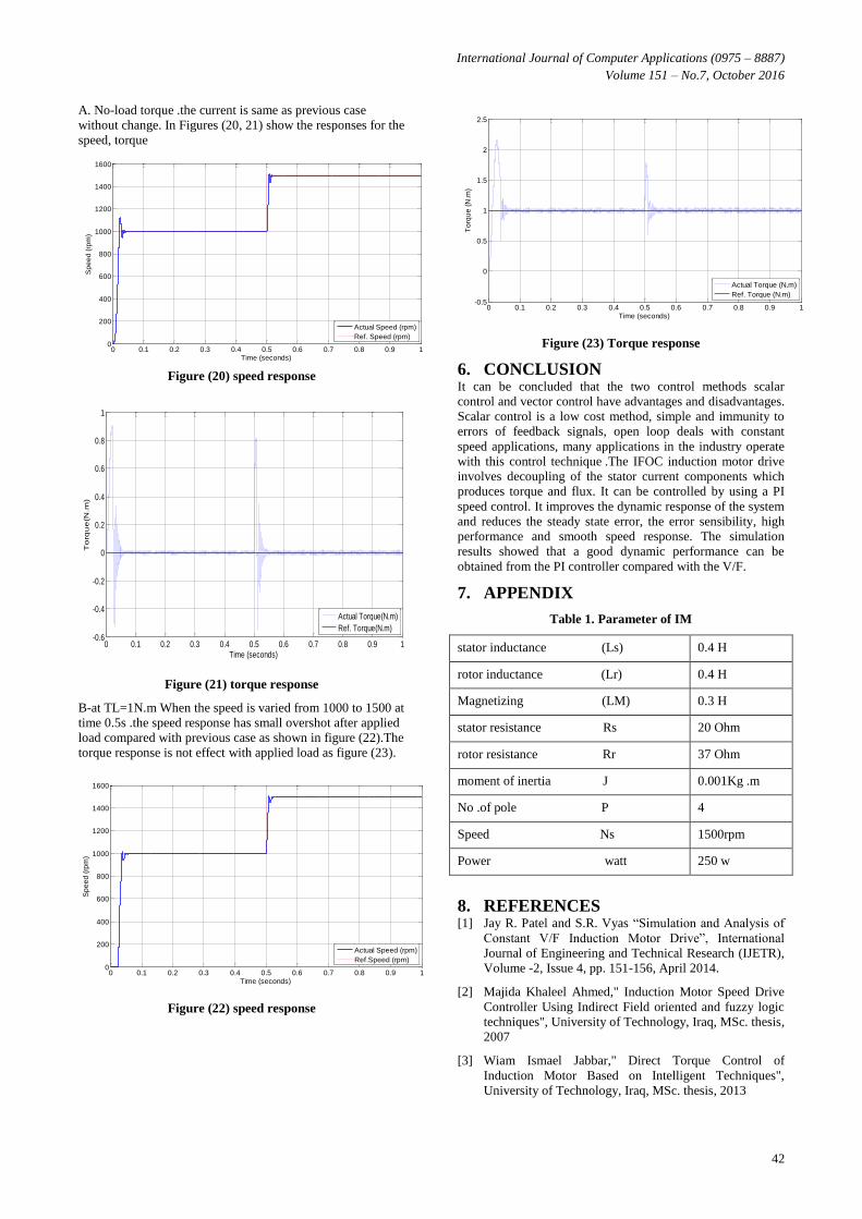
A. No-load torque .the current is same as previous case
without change. In Figures (20, 21) show the responses for the
speed, torque
Figure (20) speed response
Figure (21) torque response
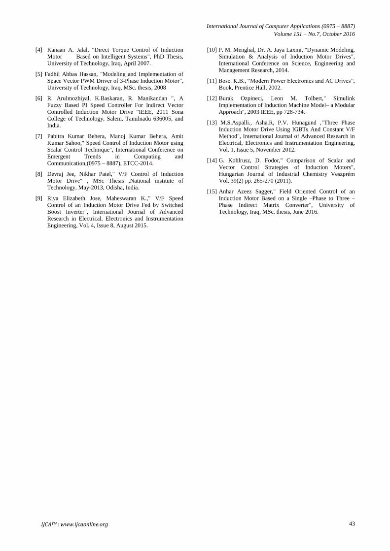
B-at TL=1N.m When the speed is varied from 1000 to 1500 at
time 0.5s .the speed response has small overshot after applied
load compared with previous case as shown in figure (22).The
torque response is not effect with applied load as figure (23).
Figure (22) speed response
Figure (23) Torque response
6. CONCLUSION It can be concluded that the two control methods scalar
control and vector control have advantages and disadvantages.
Scalar control is a low cost method, simple and immunity to
errors of feedback signals, open loop deals with constant
speed applications, many applications in the industry operate
with this control technique .The IFOC induction motor drive
involves decoupling of the stator current components which
produces torque and flux. It can be controlled by using a PI
speed control. It improves the dynamic response of the system
and reduces the steady state error, the error sensibility, high
performance and smooth speed response. The simulation
results showed that a good dynamic performance can be
obtained from the PI controller compared with the V/F.
7. APPENDIX
Table 1. Parameter of IM
stator inductance (Ls) 0.4 H
rotor inductance (Lr) 0.4 H
Magnetizing (LM) 0.3 H
stator resistance Rs 20 Ohm
rotor resistance Rr 37 Ohm
moment of inertia J 0.001Kg .m
No .of pole P 4
Speed Ns 1500rpm
Power watt 250 w
8. REFERENCES [1] Jay R. Patel and S.R. Vyas “Simulation and Analysis of
Constant V/F Induction Motor Drive”, International
Journal of Engineering and Technical Research (IJETR),
Volume -2, Issue 4, pp. 151-156, April 2014.
[2] Majida Khaleel Ahmed," Induction Motor Speed Drive
Controller Using Indirect Field oriented and fuzzy logic
techniques", University of Technology, Iraq, MSc. thesis,
2007
[3] Wiam Ismael Jabbar," Direct Torque Control of
Induction Motor Based on Intelligent Techniques",
University of Technology, Iraq, MSc. thesis, 2013
0 0.1 0.2 0.3 0.4 0.5 0.6 0.7 0.8 0.9 10
200
400
600
800
1000
1200
1400
1600
Time (seconds)
Sp
ee
d (
rpm
)
Actual Speed (rpm)
Ref. Speed (rpm)
0 0.1 0.2 0.3 0.4 0.5 0.6 0.7 0.8 0.9 1-0.6
-0.4
-0.2
0
0.2
0.4
0.6
0.8
1
Time (seconds)
To
rqu
e(N
.m)
Actual Torque(N.m)
Ref. Torque(N.m)
0 0.1 0.2 0.3 0.4 0.5 0.6 0.7 0.8 0.9 10
200
400
600
800
1000
1200
1400
1600
Time (seconds)
Sp
ee
d (
rpm
)
Actual Speed (rpm)
Ref.Speed (rpm)
0 0.1 0.2 0.3 0.4 0.5 0.6 0.7 0.8 0.9 1-0.5
0
0.5
1
1.5
2
2.5
Time (seconds)
To
rqu
e (
N.m
)
Actual Torque (N.m)
Ref. Torque (N.m)
International Journal of Computer Applications (0975 – 8887)
Volume 151 – No.7, October 2016
43
[4] Kanaan A. Jalal, "Direct Torque Control of Induction
Motor Based on Intelligent Systems", PhD Thesis,
University of Technology, Iraq, April 2007.
[5] Fadhil Abbas Hassan, "Modeling and Implementation of
Space Vector PWM Driver of 3-Phase Induction Motor”,
University of Technology, Iraq, MSc. thesis, 2008
[6] R. Arulmozhiyal, K.Baskaran, R. Manikandan ", A
Fuzzy Based PI Speed Controller For Indirect Vector
Controlled Induction Motor Drive "IEEE, 2011 Sona
College of Technology, Salem, Tamilnadu 636005, and
India.
[7] Pabitra Kumar Behera, Manoj Kumar Behera, Amit
Kumar Sahoo," Speed Control of Induction Motor using
Scalar Control Technique", International Conference on
Emergent Trends in Computing and
Communication,(0975 – 8887), ETCC-2014.
[8] Devraj Jee, Nikhar Patel," V/F Control of Induction
Motor Drive" , MSc Thesis ,National institute of
Technology, May-2013, Odisha, India.
[9] Riya Elizabeth Jose, Maheswaran K.," V/F Speed
Control of an Induction Motor Drive Fed by Switched
Boost Inverter", International Journal of Advanced
Research in Electrical, Electronics and Instrumentation
Engineering, Vol. 4, Issue 8, August 2015.
[10] P. M. Menghal, Dr. A. Jaya Laxmi, "Dynamic Modeling,
Simulation & Analysis of Induction Motor Drives",
International Conference on Science, Engineering and
Management Research, 2014.
[11] Bose. K.B., “Modern Power Electronics and AC Drives”,
Book, Prentice Hall, 2002.
[12] Burak Ozpineci, Leon M. Tolbert," Simulink
Implementation of Induction Machine Model– a Modular
Approach", 2003 IEEE, pp 728-734.
[13] M.S.Aspalli., Asha.R, P.V. Hunagund ,"Three Phase
Induction Motor Drive Using IGBTs And Constant V/F
Method", International Journal of Advanced Research in
Electrical, Electronics and Instrumentation Engineering,
Vol. 1, Issue 5, November 2012.
[14] G. Kohlrusz, D. Fodor," Comparison of Scalar and
Vector Control Strategies of Induction Motors",
Hungarian Journal of Industrial Chemistry Veszprém
Vol. 39(2) pp. 265-270 (2011).
[15] Anhar Azeez Sagger," Field Oriented Control of an
Induction Motor Based on a Single –Phase to Three –
Phase Indirect Matrix Converter", University of
Technology, Iraq, MSc. thesis, June 2016.
IJCATM : www.ijcaonline.org