Embed Size (px)
Citation preview

International Journal of Computer Applications (0975 – 8887)
Volume 121 – No.8, July 2015
11
Cutting Forces in Drilling Operation: Measurement and
Modeling for Medium-scale Manufacturing Firms
Gurumukh Das
Department of Mechanical Engineering Faculty of Engineering
Dayalbagh Educational Institute, Agra, INDIA
Padam Das
Department of Mechanical Engineering Faculty of Engineering
Dayalbagh Educational Institute, Agra, INDIA
ABSTRACT
Advanced manufacturing systems often caters to rapidly
changing product specification determination by the
continuously increasing productivity, flexibility and quality
demands. The estimation of cutting forces is mandatory to
select tools and accessories for machining. Complex
interrelationships exist between process parameters and these
forces. In the present work, the applicability and relative
effectiveness of artificial neural network based model has
been investigated for rapid estimation of cutting forces. The
results obtained are found to correlate well with the actual
experimental readings of cutting forces. Experiments were
conducted at different process parameters of cutting in
Drilling operation. The proposed work has wide application in
selection of tools and online tool wear monitoring.
General Terms
Measurement and modeling of Cutting forces.
Keywords
Drilling; Cutting forces; Cutting process parameters; Artificial
neural networks (ANNs).
1. INTRODUCTION The research in the area of metal cutting and machine tool is a
fascinating experience. The Machining process is generally
adopted to get higher surface finish, close tolerance, and
complex geometrical shape that are otherwise difficult to
obtain. The main problem is that all the manufacturing
processes available for metal removal are probably the most
expensive one. This is because of the substantial amount of
metal removal taking place from the raw material in the form
of chips in order to achieve the required shape. A lot of heat
energy is generated in the process of metal cutting which is
another reason for expensiveness of the process [1].
In the market with an increased demand for quality
manufacturing along with the short lead time and short
product life cycles, the increasing consumer awareness always
looks for the cost factor and quality so this becomes most
important for the manufacturers to take some initiative steps.
To achieve all these, some questions arise in the mind of a
production engineer: 1) Which is the most suitable and
economical tool for a particular metal cutting operation? 2)
For what specification, power consumption is minimum? 3)
How much heat is generated in the metal cutting process? 4)
What type of coolant should be used? 5) What should be the
optimal flow rate of coolant? etc. To answer all these
questions, the estimation of cutting forces is a must [2].
In the world of manufacturing, everyone is stressing on the
need of fast accessing the information related to tool
management systems i.e. providing the right tool at the right
place and at the right time. If there is dedicated transfer line, it
will be sufficient to determine the tool with required strength
at the beginning of the machining, but in batch-type
production having no flexible manufacturing system and any
advanced information facilities, it will not be possible for a
production engineer at work floor to determine the necessary
tool with sufficient strength for a new job settings (in terms of
changed operational parameters and work material). This
situation compels him to go to either production planning and
control (PPC) department or tool design department. This
whole cycle makes the manufacturing systems sluggish and
cumbersome [3].
Besides this, what happens sometimes is that at the production
floor, there may be frequent and slight changes of work
material, process and process parameter then every time
production engineer will have to contact to the above
departments. This results into a large non-productive time of
machine tool as well as worker’s idle time, most of the times
resulting into production halt [4].
To avoid this situation, the trained neural network (NN)
model can be made available on a computer located at the
production floor itself to production engineers for estimation
of cutting forces. They can give the inputs to NN model in the
form of process parameters, type of work material, etc. By
doing so, with no lapse of time they will get all cutting forces
acting on the tool in real time situation and matching the
values of these forces with tool handbooks, they can choose
the tool with required strength, which can perform operation
satisfactorily [5-6].
It solves the most of the complications of production
engineer’s job and a lot of non-productive time can be saved.
This system becomes an essential part of production system
especially in those, where every department is not integrated
through a software system to access information from one
department to another rapidly. It will work well in medium-
scale manufacturing industries [7].
2. LITERATURE REVIEW Modeling can be said to have had its beginning as an
organized process in the late 1890s to early 1900s originated
with F.W. Taylor’s pioneering engineering research and
development of empirical methodology (and equations) for
estimating reasonably economic machining conditions.
Science-based modeling began to emerge in the 1940s by
Merchant’s physics-based modeling in a machining process.
Computer-based modeling, the “watershed” event of the
advent of digital computer technology and its application to
manufacturing in general, was started in the 1970s [8].

International Journal of Computer Applications (0975 – 8887)
Volume 121 – No.8, July 2015
12
Osman, Xistris and Chahil (1979) made the measurement and
analysis of torque and thrust in drilling mild steel with twist
drills using a specially designed two-component piezoelectric
dynamometer which was both statically and dynamically
calibrated [9].
Koplev, Lystrup and Vorm (1983) examined the cutting of
unidirectional CFRP, perpendicular as well as parallel to the
fiber orientation. They measured cutting forces parallel and
perpendicular to the cutting direction for various parameters,
and correlated the results to the formation of chips and the
wear of the tool [10].
Veniali, Di Llio and Tagliaferri (1995) experimentally
investigated major drilling characteristics of Aramid fiber-
reinforced plastics. The chips appeared were found to be
highly deformed and tend to smear on the tool and the forces
and torque to be more influenced by the tool diameter than by
the feed rate and cutting speed [11].
The object of the study by Fuh and Wang (1997) was to
model and forecast the grinding force for the creep feed
grinding process, using error distribution function based back-
propagation neural network improved [12].
To model drilling processes, Lee, Liu and Tarng (1998)
described the use of an abductive network composing of a
number of self-organized functional nodes by means of a
predicted squared error criterion. They predicted the drilling
performance in terms of tool life, metal removal rate, thrust
force and torque using above network. A simulated annealing
technique with a performance index was then applied to
optimize process parameters [13].
Szecsi (1999) proposed a method for cutting forces modeling
using multi-layer feed-forward back-propagation neural
networks trained by the experimental machining data for
simulating and defining the cutting forces in the process [14].
Elhachimi, Torbaty, Joyot (1999) presented a new theoretical
model to predict thrust and torque in high speed drilling. This
technique was consisted of continuous measurement of
cutting forces on the twist drill [15].
Lachaud, Piquet, Collombet and Surcin (2001) gave a model
linking drill-bit axial penetration in terms of thrust force [16].
Ramulu, Branson and Kim (2001) experimented with variety
of drill-bit materials to perform holes on graphite /
bismaleimide titanium work with a standard geometry. The
purpose was to understand and characterize the process [17].
Zuperl and Cus (2004) used ANN technique to find out the
cutting forces for ball-end milling operation and to compare
predictability ANN and analytical techniques [18].
Sheng and Tomizuka (2006) proposed an intelligent technique
to model cutting forces in drilling process. For that, NN
models were developed [19].
The principal aim of the work done by Abrão, Faria, Campos
Rubio, Reis and Paulo Davim (2007) was to perform a survey
on the machining of composite materials [20].
Aykut, Gölcü, Semiz and Ergür (2007) used scaled conjugate
gradient feed-forward back-propagation neural network
approach to model the effects of machinability on cutting
parameters for face milling of stellite 6. [21].
Tsao and Hocheng (2008) presented the prediction and
evaluation of thrust force and surface roughness in drilling of
composite material using candle stick drill. The objective of
this study was to establish a correlation between the feed rate,
spindle speed and drill diameter with the induced thrust force
and surface roughness in drilling composite laminate using
RBFN [22].
3. SELECTION OF MACHINE TOOL
AND WORK MATERIAL In this work, we have selected a Radial Drilling Machine
(installed at Machine Shop, Mechanical Engineering
Workshop, Faculty of Engineering, Dayalbagh Educational
Institute, Dayalbagh, Agra) as a machine tool. It is shown in
Fig. 1. Specifically, Drilling machine is selected because it
comes under the category of Primary machine tools as it
performs primary functions but extent to which it can also be
exploited to perform secondary functions. This is the most
commonly used machine primarily designed to perform a
variety of machining operations on a wide range of
components. It is also known as a General purpose machine.
By their nature of generalization, the general-purpose
machines are capable to carry out a variety of tasks and the
estimation of the cutting forces through these machines are
also applicable to the production machine tools and the
special purpose machine tools.
Fig 1: Experimental setup of Strain-gauge type Drilling-
tool dynamometer fitted on Radial Drilling Machine
The selection the work materials has been done out of a
variety of engineering materials that are extensively used in
the industries. These materials are used in the industries either
individually or a combination of them is used. So, it becomes
easier to estimate the cutting forces with the help of these
materials for the large area of industrial materials. These
materials are selected in this way that they cover wide range
of yield strength from Mild steel to Aluminium. The five most
commonly used materials selected for the experimentation are
Mild steel (MS), Cast iron (CI), Copper (Cu), Brass, and
Aluminium (Al).

International Journal of Computer Applications (0975 – 8887)
Volume 121 – No.8, July 2015
13
4. CUTTING FORCES To investigate the performance of drill bit during drilling
process, the measurements of cutting forces are essential. This
helps in analyzing: 1) the effects of speed and feed on the
cutting action of the drill, 2) the effects of mechanical
properties of work material on the drilling forces, and 3)
forces exerted on Drilling machine parts, jigs and fixtures, and
the effect of these forces on the dimensional accuracies of the
drilled holes.
The force R acting on both the lips of drill in drilling process
may be resolved into three mutually perpendicular force
components: axial force (FA) along the axis of drill, radial
force (FR) along the radial direction of drill, and tangential
force (FT) perpendicular to the force components FA and FR.
Taking an ideal case of the drill with both the lips identical,
the radial force components FR at both lips will get cancelled.
Out of the remaining two components, axial components FA
acting on both the lips will add to act as an axial thrust P on
the drill; while the tangential components FT acting on both
the lips will form as a torque M opposing the rotation of the
drill (see Fig. 2) [23-24].
Fig 2: Resulting axial thrust and torque
5. ARTIFICIAL NEURAL NETWORKS Back Propagation (BP) neural network is a multiple-layer
network with one input layer, one output layer and some
hidden layers between the input and output layers. Its learning
procedure is based on a gradient search with least sum
squared optimality criterion. Gradient is calculated by a
partial derivative of sum-squared error with respect to
weights. Input is given to ANN after assigning random initial
weights, each neuron is computed, and weighted sum of
inputs from preceding layer neurons is used as an input to
succeeding layers. Towards the end, the weighted sum of
networks is calculated [25-26].
A two-layer feed-forward network with three input neurons,
eight neurons in the first hidden layer, six neurons in the
second hidden layer, and two output neurons in the output
layer is designed and trained with the LM learning rule. The
logarithm and tangent of sigmoid functions are used in the
hidden layers, and the output layer has a pure linear neuron
(see Fig. 3). Fig. 4 shows the training graph between the sum-
squared error and the number of epochs.
Spindle speed (in RPM), work material (numbered as 1 to 5)
and Drill diameter (in mm) are the three input parameters and
output parameters are the resulting cutting forces, viz., torque
(in N-m) and axial thrust (in N) [27].
Fig 3: Neural network architecture
Fig 4: Training graph
International Journal of Computer Applications (0975 – 8887)
Volume 121 – No.8, July 2015
14
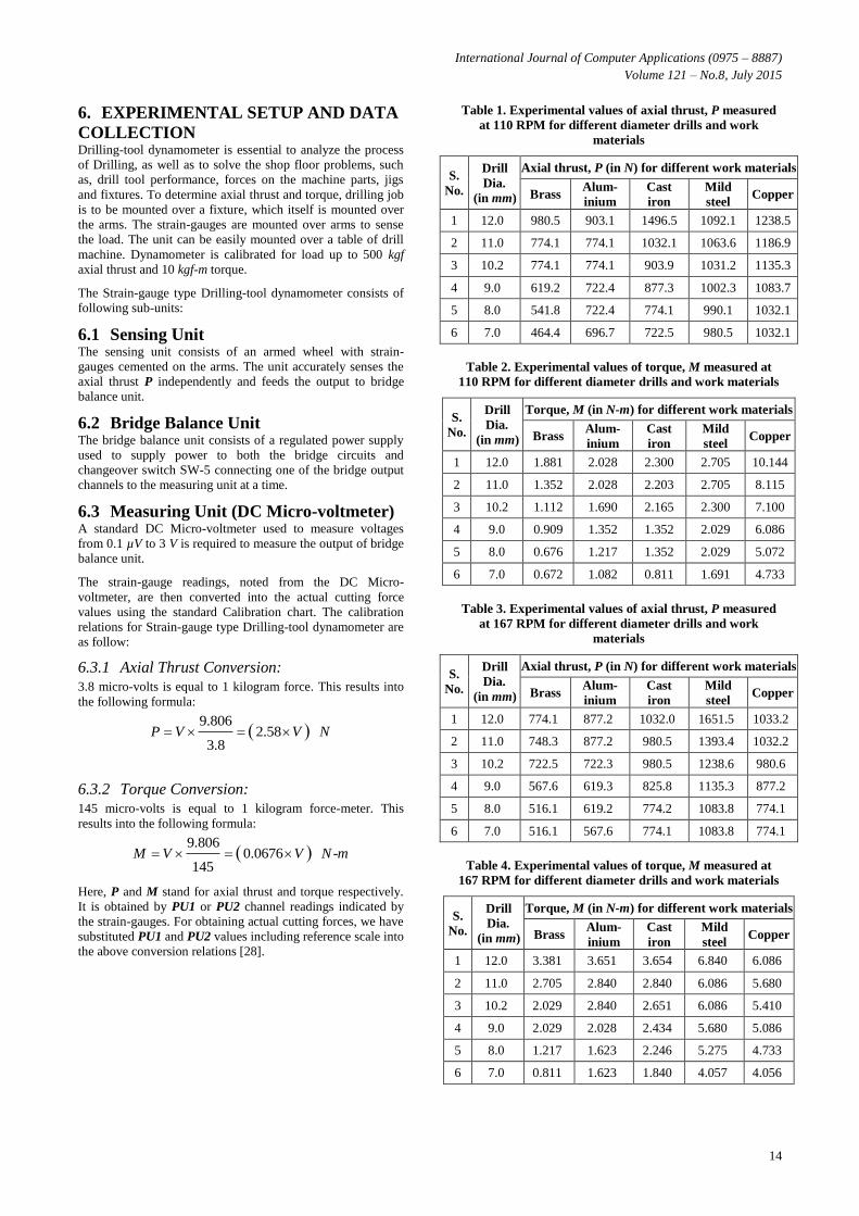
6. EXPERIMENTAL SETUP AND DATA
COLLECTION Drilling-tool dynamometer is essential to analyze the process
of Drilling, as well as to solve the shop floor problems, such
as, drill tool performance, forces on the machine parts, jigs
and fixtures. To determine axial thrust and torque, drilling job
is to be mounted over a fixture, which itself is mounted over
the arms. The strain-gauges are mounted over arms to sense
the load. The unit can be easily mounted over a table of drill
machine. Dynamometer is calibrated for load up to 500 kgf
axial thrust and 10 kgf-m torque.
The Strain-gauge type Drilling-tool dynamometer consists of
following sub-units:
6.1 Sensing Unit The sensing unit consists of an armed wheel with strain-
gauges cemented on the arms. The unit accurately senses the
axial thrust P independently and feeds the output to bridge
balance unit.
6.2 Bridge Balance Unit The bridge balance unit consists of a regulated power supply
used to supply power to both the bridge circuits and
changeover switch SW-5 connecting one of the bridge output
channels to the measuring unit at a time.
6.3 Measuring Unit (DC Micro-voltmeter) A standard DC Micro-voltmeter used to measure voltages
from 0.1 µV to 3 V is required to measure the output of bridge
balance unit.
The strain-gauge readings, noted from the DC Micro-
voltmeter, are then converted into the actual cutting force
values using the standard Calibration chart. The calibration
relations for Strain-gauge type Drilling-tool dynamometer are
as follow:
6.3.1 Axial Thrust Conversion:
3.8 micro-volts is equal to 1 kilogram force. This results into
the following formula:
9.806
2.583.8
P V V N
6.3.2 Torque Conversion:
145 micro-volts is equal to 1 kilogram force-meter. This
results into the following formula:
9.806
0.0676 -145
M V V N m
Here, P and M stand for axial thrust and torque respectively.
It is obtained by PU1 or PU2 channel readings indicated by
the strain-gauges. For obtaining actual cutting forces, we have
substituted PU1 and PU2 values including reference scale into
the above conversion relations [28].
Table 1. Experimental values of axial thrust, P measured
at 110 RPM for different diameter drills and work
materials
S.
No.
Drill
Dia.
(in mm)
Axial thrust, P (in N) for different work materials
Brass Alum-
inium
Cast
iron
Mild
steel Copper
1 12.0 980.5 903.1 1496.5 1092.1 1238.5
2 11.0 774.1 774.1 1032.1 1063.6 1186.9
3 10.2 774.1 774.1 903.9 1031.2 1135.3
4 9.0 619.2 722.4 877.3 1002.3 1083.7
5 8.0 541.8 722.4 774.1 990.1 1032.1
6 7.0 464.4 696.7 722.5 980.5 1032.1
Table 2. Experimental values of torque, M measured at
110 RPM for different diameter drills and work materials
S.
No.
Drill
Dia.
(in mm)
Torque, M (in N-m) for different work materials
Brass Alum-
inium
Cast
iron
Mild
steel Copper
1 12.0 1.881 2.028 2.300 2.705 10.144
2 11.0 1.352 2.028 2.203 2.705 8.115
3 10.2 1.112 1.690 2.165 2.300 7.100
4 9.0 0.909 1.352 1.352 2.029 6.086
5 8.0 0.676 1.217 1.352 2.029 5.072
6 7.0 0.672 1.082 0.811 1.691 4.733
Table 3. Experimental values of axial thrust, P measured
at 167 RPM for different diameter drills and work
materials
S.
No.
Drill
Dia.
(in mm)
Axial thrust, P (in N) for different work materials
Brass Alum-
inium
Cast
iron
Mild
steel Copper
1 12.0 774.1 877.2 1032.0 1651.5 1033.2
2 11.0 748.3 877.2 980.5 1393.4 1032.2
3 10.2 722.5 722.3 980.5 1238.6 980.6
4 9.0 567.6 619.3 825.8 1135.3 877.2
5 8.0 516.1 619.2 774.2 1083.8 774.1
6 7.0 516.1 567.6 774.1 1083.8 774.1
Table 4. Experimental values of torque, M measured at
167 RPM for different diameter drills and work materials
S.
No.
Drill
Dia.
(in mm)
Torque, M (in N-m) for different work materials
Brass Alum-
inium
Cast
iron
Mild
steel Copper
1 12.0 3.381 3.651 3.654 6.840 6.086
2 11.0 2.705 2.840 2.840 6.086 5.680
3 10.2 2.029 2.840 2.651 6.086 5.410
4 9.0 2.029 2.028 2.434 5.680 5.086
5 8.0 1.217 1.623 2.246 5.275 4.733
6 7.0 0.811 1.623 1.840 4.057 4.056

International Journal of Computer Applications (0975 – 8887)
Volume 121 – No.8, July 2015
15
Table 5. Neural network prediction (values) of axial
thrust, P at 110 RPM for different diameter drills and
work materials
S.
No.
Drill
Dia.
(in mm)
Axial thrust, P (in N) for different work materials
Brass Alum-
inium
Cast
iron
Mild
steel Copper
1 12.0 984.1 899.5 1495.2 1090.6 1239.0
2 11.0 773.1 775.9 1030.8 1065.4 1188.2
3 10.2 773.0 775.2 904.3 1030.3 1130.2
4 9.0 618.2 725.7 875.9 1003.7 1080.3
5 8.0 540.3 725.7 770.0 992.5 1033.7
6 7.0 460.7 700.3 722.0 981.5 1032.2
Table 6. Neural network prediction (values) of torque, M
at 110 RPM for different diameter drills and work
materials
S.
No.
Drill
Dia.
(in mm)
Torque, M (in N-m) for different work materials
Brass Alum-
inium
Cast
iron
Mild
steel Copper
1 12.0 2.003 2.281 2.350 2.875 9.234
2 11.0 1.551 2.029 2.216 2.721 8.226
3 10.2 1.100 1.722 2.156 2.229 7.009
4 9.0 0.922 1.361 1.360 2.032 5.966
5 8.0 0.687 1.220 1.344 2.001 5.001
6 7.0 0.661 1.090 0.823 1.778 4.562
Table 7. Neural network prediction (values) of axial
thrust, P at 167 RPM for different diameter drills and
work materials
S.
No.
Drill
Dia.
(in mm)
Axial thrust, P (in N) for different work materials
Brass Alum-
inium
Cast
iron
Mild
steel Copper
1 12.0 772.5 872.5 1028.2 1650.2 1028.2
2 11.0 768.1 871.2 978.4 1328.4 1028
3 10.2 720.2 728.1 972.8 1236.3 982.6
4 9.0 562.6 618.3 824.5 1132.2 879.3
5 8.0 515.2 617.3 784.2 1082.8 772.6
6 7.0 514.2 565.8 771.4 1080.4 770.28
Table 8. Neural network prediction (values) of torque, M
at 167 RPM for different diameter drills and work
materials
S.
No.
Drill
Dia.
(in mm)
Torque, M (in N-m) for different work materials
Brass Alum-
inium
Cast
iron
Mild
steel Copper
1 12.0 3.28 3.72 3.62 6.96 6.26
2 11.0 2.82 2.72 3.42 6.21 5.98
3 10.2 2.41 2.68 3.14 6.02 5.63
4 9.0 2.18 2.21 2.74 5.62 5.32
5 8.0 1.12 1.62 2.65 5.18 4.83
6 7.0 1.01 1.62 2.23 4.13 4.15
7. RESULTS The comparison of measured values of cutting forces through
rigorous experimentation and those predicted by neural
network are shown in Fig. 5 to 8.
Fig 5: Comparison between Experimental and NN values
of torque, M at 110 RPM for different diameter drills and
work materials
Fig 6: Comparison between Experimental and NN values
of axial thrust, P at 110 RPM for different diameter drills
and work materials
Fig 7: Comparison between Experimental and NN values
of torque, M at 167 RPM for different diameter drills and
work materials
International Journal of Computer Applications (0975 – 8887)
Volume 121 – No.8, July 2015
16
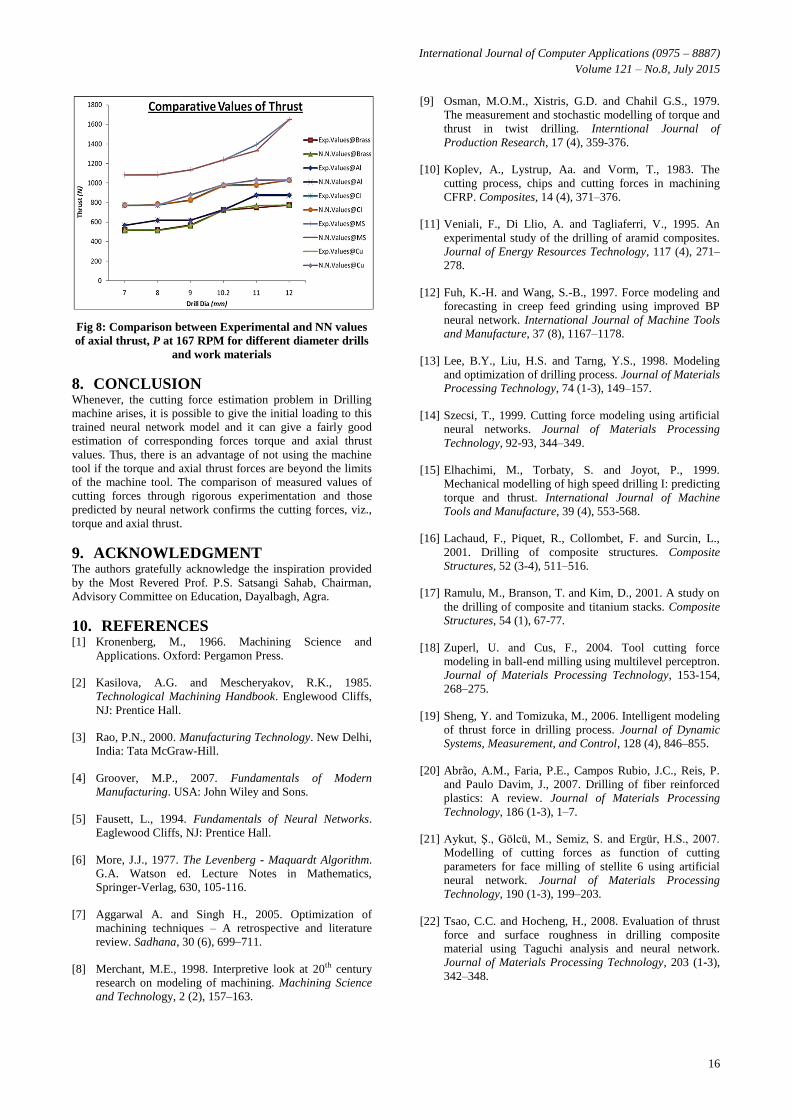
Fig 8: Comparison between Experimental and NN values
of axial thrust, P at 167 RPM for different diameter drills
and work materials
8. CONCLUSION Whenever, the cutting force estimation problem in Drilling
machine arises, it is possible to give the initial loading to this
trained neural network model and it can give a fairly good
estimation of corresponding forces torque and axial thrust
values. Thus, there is an advantage of not using the machine
tool if the torque and axial thrust forces are beyond the limits
of the machine tool. The comparison of measured values of
cutting forces through rigorous experimentation and those
predicted by neural network confirms the cutting forces, viz.,
torque and axial thrust.
9. ACKNOWLEDGMENT The authors gratefully acknowledge the inspiration provided
by the Most Revered Prof. P.S. Satsangi Sahab, Chairman,
Advisory Committee on Education, Dayalbagh, Agra.
10. REFERENCES [1] Kronenberg, M., 1966. Machining Science and
Applications. Oxford: Pergamon Press.
[2] Kasilova, A.G. and Mescheryakov, R.K., 1985.
Technological Machining Handbook. Englewood Cliffs,
NJ: Prentice Hall.
[3] Rao, P.N., 2000. Manufacturing Technology. New Delhi,
India: Tata McGraw-Hill.
[4] Groover, M.P., 2007. Fundamentals of Modern
Manufacturing. USA: John Wiley and Sons.
[5] Fausett, L., 1994. Fundamentals of Neural Networks.
Eaglewood Cliffs, NJ: Prentice Hall.
[6] More, J.J., 1977. The Levenberg - Maquardt Algorithm.
G.A. Watson ed. Lecture Notes in Mathematics,
Springer-Verlag, 630, 105-116.
[7] Aggarwal A. and Singh H., 2005. Optimization of
machining techniques – A retrospective and literature
review. Sadhana, 30 (6), 699–711.
[8] Merchant, M.E., 1998. Interpretive look at 20th century
research on modeling of machining. Machining Science
and Technology, 2 (2), 157–163.
[9] Osman, M.O.M., Xistris, G.D. and Chahil G.S., 1979.
The measurement and stochastic modelling of torque and
thrust in twist drilling. Interntional Journal of
Production Research, 17 (4), 359-376.
[10] Koplev, A., Lystrup, Aa. and Vorm, T., 1983. The
cutting process, chips and cutting forces in machining
CFRP. Composites, 14 (4), 371–376.
[11] Veniali, F., Di Llio, A. and Tagliaferri, V., 1995. An
experimental study of the drilling of aramid composites.
Journal of Energy Resources Technology, 117 (4), 271–
278.
[12] Fuh, K.-H. and Wang, S.-B., 1997. Force modeling and
forecasting in creep feed grinding using improved BP
neural network. International Journal of Machine Tools
and Manufacture, 37 (8), 1167–1178.
[13] Lee, B.Y., Liu, H.S. and Tarng, Y.S., 1998. Modeling
and optimization of drilling process. Journal of Materials
Processing Technology, 74 (1-3), 149–157.
[14] Szecsi, T., 1999. Cutting force modeling using artificial
neural networks. Journal of Materials Processing
Technology, 92-93, 344–349.
[15] Elhachimi, M., Torbaty, S. and Joyot, P., 1999.
Mechanical modelling of high speed drilling I: predicting
torque and thrust. International Journal of Machine
Tools and Manufacture, 39 (4), 553-568.
[16] Lachaud, F., Piquet, R., Collombet, F. and Surcin, L.,
2001. Drilling of composite structures. Composite
Structures, 52 (3-4), 511–516.
[17] Ramulu, M., Branson, T. and Kim, D., 2001. A study on
the drilling of composite and titanium stacks. Composite
Structures, 54 (1), 67-77.
[18] Zuperl, U. and Cus, F., 2004. Tool cutting force
modeling in ball-end milling using multilevel perceptron.
Journal of Materials Processing Technology, 153-154,
268–275.
[19] Sheng, Y. and Tomizuka, M., 2006. Intelligent modeling
of thrust force in drilling process. Journal of Dynamic
Systems, Measurement, and Control, 128 (4), 846–855.
[20] Abrão, A.M., Faria, P.E., Campos Rubio, J.C., Reis, P.
and Paulo Davim, J., 2007. Drilling of fiber reinforced
plastics: A review. Journal of Materials Processing
Technology, 186 (1-3), 1–7.
[21] Aykut, Ş., Gölcü, M., Semiz, S. and Ergür, H.S., 2007.
Modelling of cutting forces as function of cutting
parameters for face milling of stellite 6 using artificial
neural network. Journal of Materials Processing
Technology, 190 (1-3), 199–203.
[22] Tsao, C.C. and Hocheng, H., 2008. Evaluation of thrust
force and surface roughness in drilling composite
material using Taguchi analysis and neural network.
Journal of Materials Processing Technology, 203 (1-3),
342–348.

International Journal of Computer Applications (0975 – 8887)
Volume 121 – No.8, July 2015
17
[23] Gilbert, W.W., 1950. Economics of machining. In
Machining – Theory and practice. Transactions of
American Society for Metals, 476–480.
[24] Armarego, E.J.A. and Brown, R.H., 1969. The
Machining of Metals. Englewood Cliffs, NJ: Prentice
Hall.
[25] Singh, R., Das, G. and Setia, R., 2007. Parametric
modeling of a rotary furnace for agile production of
castings with artificial neural networks. International
Journal of Agile Manufacturing, 10 (2), 137–147.
[26] Singh, R., Setia, R. and Das, G., 2007. Modeling and
optimization of rotary furnace parameters using artificial
neural networks and genetic evolutionary algorithms. In
Proceedings of the 31st National Systems Conference,
Manipal, India, P.No. 75.
[27] Brewer, R.C. and Rueda, R., 1963. A simplified
approach to the optimum selection of machining
parameters. Eng. Dig., 24(9), 133–150.
[28] Ai, X. and Xiao, S., 1985. Metal Cutting Condition
Handbook. China: Mechanics Industry Press.
IJCATM : www.ijcaonline.org