Embed Size (px)
Citation preview

Specifications for
Copper Intra Uterine Contraceptive Device 375
1. Scope
1.1 The standard covers the shape, dimensions and other requirements for Copperintra-uterine contraceptive device, 375 and its components.
2. Normative references
The following Indian and international standards are necessary adjunct to thisstandard. However subsequent amendments have been made to the contents of thefollowing references as per the requirements of this standard.
~ IS 3395: 1984, Low density polyethylene materials for moulding and extrusion
(First revision)
~ IS 12418 (Part 3):1987, Intra Uterine Contraceptive device: Part 3 Packaging
and labeling
~ The Cu 375 Intra Uterine Contraceptive Device (JUD) WHOIUNFPA
Specification, 2011 (UNFPAICPHI09131)
~ ASTM D638: 2010, 10 Standard Test Method for Tensile Properties of
Plastics
~ ASTM D790 - 10 Standard Test Methods for Flexural Properties of
Unreinforced and Reinforced Plastics and Electrical Insulating Materials
~ ISO 10993: Standards for evaluating the biocompatibility of a medical device
prior to a clinical study. Special reference to ISO 10993:1; ISO:10993: 5;
ISO 10993:18
1
3. Shapes and Dimensions
Cross section of wing Frontal View of Fingerstub
Wing
Vertical Stem withCopper wire around
----- Terminal Enlargement
1\\01------ Tie (Threads)
Rounded end ofFinger stub
'----_ Body of Fingerstub
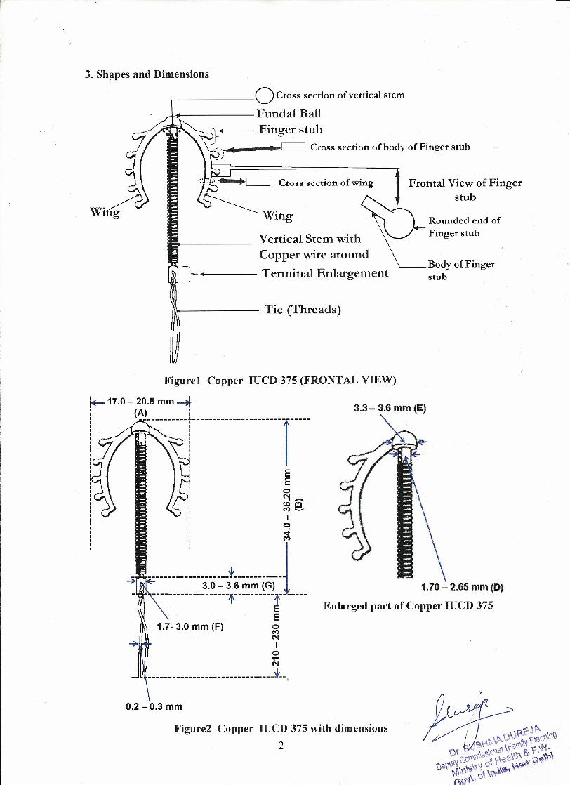
Figure! Copper IUCD 375 (FRONTAL VIEW)
!+-17.0 - 20.5 mm ~
(111----------1----------------------'[-----
II E
EoN<DmM-Io-o:tM
-~~~~~~~~~~~~~~::~~~~~~~!;;~----EE
1.7- 3.0 mm (F) gN
~ Io.•...N
-------------------------------~-- •
0.2 -0.3 mm
3.3 - 3.6 mm (E)
1.70-2.65 mm (D)
Enlarged part of Copper IUCD 375
Figure2 Copper IUCD 375 with dimensions
2

- --*-_. 1.7 - 2.8 mm (H)-t--
0.5 - 0.9 mm (C)
0.5 - 0.9 mm ( Form C)
10mmtl1l4--- Hole for threads
Figure3 Copper IUCD 375
(CORONAL VIEW)IOmm
Copper IUCD 375 (FRONTAL VIEW)
rFlangeInsertionTube
~----.~,
LIVeDTie/Threads
Figure 4 Copper IUCD 375 with Insertion Tube
3.1 General Description
The rUCD as shown in Figure 1 represents the rUCD in the "Frontal plane" andrUCD as shown in Figure 3 is in the "Coronal plane".
The Copper rUCD 375 consists of a n shaped frame comprising of two 'Wings'joined to an enlargement of the Vertical Stem termed the "Fundal Ball". The shape isloosely described as inverted 'U' shape. The shape shall be as shown in Figure 1.The vertical stem has a terminal enlargement at the bottom to guard against cervicalpenetration. A small hole is located on the vertical stem to act as an anchor for e
3

copper wire which is wound over vertical stem. A filament is tied in a knot through asmall hole in the terminal enlargement to provide two equal length marker threads(termed as "Tie"), as a means to locate andremove the device. There will be 5 'Fingerstubs' on both wings.
The device is supplied with a tubular insertion instrument as shown in Figure 4. Amoveable plastic flange is positioned on the insertion tube to assist in positioning theIUCD correctly in relation to the uterine fundus during insertion thus minimizing riskof perforation of the uterus.The IUCD device with the insertion instrument is pre-positioned ready for insertion asshown in Figure 5 is supplied sterile within a sealed primary pack.
The IUCD and associated components are made up of:• Frame - Low-density polyethylene(LDPE) or High Density Polyethylene
(HDPE) + ethylene vinyl acetate copolymer• Wire wound around Vertical stem - Copper• Tie - Nylon• Insertion Tube - HDPE (High Density Polyethylene) or gamma radiation
resistant Polypropylene• Flange - Polyvinyl chloride• Package - Polyester and polyethylene
FRAME
MaterialThe Frame shall be made from Low-Density polyethylene (LDPE) or GammaRadiation resistant High Density Polyethylene (HDPE) + ethylene vinyl acetatecopolymer free of stabilizers having a minimum tensile strength of 15 MPa and a 2%secant flexural modulus in the range 133.5 MPa to 180.6 MPa.The material shall be blended with 20% to 24% barium sulphate with a particle size of95% less than 10 micron. The implant material shall pass the cytotoxicity tests,implantation test and extractables test as per the international standards.The finger stubs shall be moulded together with the wings and have the same materialas that of the frame.
Dimensions and Form
• Dimension A: Width of horizontal wings shall lie between 17.00 to 20.5 mmDimension B: Vertical stem length shall lie between 34.00 to 36.20 mmDimension C: Thickness of wings shall lie between 0.5 to 0.9 mmDimension D: Diameter of vertical stem (before winding) shall lie between1.70 to 2.65 mm, a uniform over the length of the stem between fundal balland terminal enlargement.Dimension E: Fundal ball should be solid hemisphere with diameter 3.3 to 3.6mmThe size of the terminal enlargement should be in the range of:Dimension F: Lateral - 1.7 to 3.0 mmDimension G: Vertical- 3.0 to 3.6 mmDimension H: Height of the fundal ball shall lie between 1.7 to 2.8 mmForm A: Hole for anchoring an end of the copper wire may be provided. ~)Form B: Cross section of the wings should be rectangular.
4 \JRE.Ji\ ,S\JS\"\M~0 a~i\~~\al'\'\\
Of. ro'sSiOnB1l'r· 8< :,\r-J-Qrl.l\\ICO~ ~uea\t~ ,.''t'V"V"', '$\f'j 01 P w~\tJ O~~"- N\\"" A f'lt\\a,''''··' -
•••
•
•
•••

• Form C:./' There will be 5 finger stubs on the either side ../' The stubs will be knob shaped as shown in Figure 1 and the thickness
of the stubs will be 0.5 to 0.9 mm as shown in figure 3../' Cross sections of the finger stubs should be rectangular ../' Finger Stubs will be sloping downwards in the frontal view. ../' Slope angle as shown in figure 5 is to be in the range of 40° to 70°
!
Angle 40 to 70°
Figure 5 Measurement of slope angle of finger stubs
Requirements and TestsThe material of the frame to meet the ISO 10993 standards for chronic biomedicalimplants Specifically the ISO 10993: 5 Cytotoxicity test, 10993: 18 Implantation andextractables test must give comparable biocompatibity as USP grade negative control.
Memory testMemory is measured in terms of recovery after acute flexion quantified by restorationof width of the horizontal wings (Dimension A). On removal and observation after 1minute of the frame following an insertion into 6 mm internal diameter tubing for 2minutes. Dimension A to be no less than 25% less than the original pre stressed widthof the wings (Provisional).
5

Insertion Flexibility test
Insertion Flexibility Test
"' ."' ."' ."' ."' ."' ."' .< .
Insertion flexibility relates to the recoiled force exerted by the wings onto the innerwall of the uterine cervix at the time of insertion of IUCD. The force to compress thewings to bring the width of the wings to 6 mm should not exceed 1 N (Provisional)
Implant Flexibility test
~.,.,...---------- •.•.•.1II!I
-"
6

Implant flexibility relates to the recoiled force when the wings are compressed byuterine contractions under normal placement of the IUCD within the uterus. The forceis quantified by the bending of the wings on application of the bilateral forceperpendicular to the wings at a point where a horizontal line of length 6 mm iscalculated from the base of the first finger stub to the centre of the fundal ball. Theforce required to displace the point towards the vertical stem by 1.5 mm is to be inthe range of 7-12 N (Provisional)
Frame shall be radio-opaque and shall have two ties for easy removal
Ash ContentAsh Content (as barium sulphate) of moulded frame shall be between 20-24 percentwhen tested in accordance with the method specified in latest Indian Pharmacopoeia.
Sterility TestWhen Copper 375 is distributed as sterile, it shall be capable of meeting therequirements of any suitable sterility test specified in latest Indian Pharmacopoeia
WIREThe copper wire should be wound tightly around the vertical stem with the loops evenspaced. "Single" or "Double"wounding format may be used. The two ends of thecopper wire are so closely positioned on the vertical stem surface that there are noprojections of the wire end.
MaterialThe wire shall be made from 99.99% pure copper.
DimensionsCopper wire of should be of 349 - 392 mm' surface area and of diameter 0.38 to0.41mmThe mass of copper wire wound shall be 310 to 360 mg.
TIE (THREADS)MaterialThe thread shall be made from Polyamide Nylon 6 or polyamide nylon 66monofilament thread. The material shall pass ISO 10993 test as applicable forchronic implantation.
Dimension
Thread LengthThread Length shall be 210 to 230 mm.Colour of the thread should be medical grade green.
Thread KnotThe knot shall be secure and not promote breakage under normal use.
Thread dimensionThe thread shall be made of Nylon of diameter 0.20 to 0.30mm.Tensile strength of the thread shall be more than 9.5 N for a force applied for 30 S.
7

Extractables testThe thread shall pass currently applicable USP extractable test class II and shall beevaluated for biological safety in accordance with ISO 10993-1: 2003 requirementsfor mucosal membrane contact devices intended for permanent contact.
INSERTION TUBE
I II·'*(---------------------------------~»I
I.I 198 - 204 mm I ..I
Figure 6 Insertion Tube Dimensions
MaterialThe insertion tube shall be made of HDPE (High Density Polyethylene) or gammaradiation resistant Polypropylene. The material shall pass the 10993: 18 Implantationand extractables test and must give comparable biocompatibity as USP grade negativecontrol
DimensionsLength must lie between 198 to 204mm.Internal Diameter must lie within 2.6 to 3.1mm.Outside Diameter must lie within 3.40 to 4.00 mm (As shown in Figure 6)
RequirementThe insertion tube must slip out of the tie and vertical stem without exerting excessivedrag force on the frame when the insertion tube is pulled in a direction axial to thevertical stem and away from the fundal ball.
TestWhen gripping the fundal ball, the frame and insertion tube assembly is held in aposition with the vertical stem being vertical and the fundal ball being topmost theinsertion tube should slip out by virtue of its own weight.
8

FLANGE
MaterialThe flan~e shall be made of polyvinyl chloride containing titanium dioxide.
I \
I~'I-------------'-1-1 L-.I~I ---,0"--->-"--'--'-'-"-""= = = ==.:=······=······="····=,,····=······=······=······=.••=:-It =f4=::.=I~===='" '=" c...:;"'=" ====•.-"-'..•...~=:=...•..•-'-="-.---=-- ..- --:-....••.-:-•.•-:-..- -..'-'.-...•..•-->'©
\ I.•••r --
I II I
/'I
:E ):; 10.9-13mm, ,
Figure 7 Insertion tube with Flange and Flange Dimensions
DimensionThe lateral length of the flange shall be in the range of 10.9 to 13 mm (as shown inFigure 7).The vertical length of the flange shall be in the range of 6 to 7 mm.Diameter of central hole shall be chosen and specified with a tolerance to achieve theflange displacement force. The shape and dimensions of the central hole may bechanged to facilitate meeting the specified flange displacement force
Flange Displacement ForceFlange selected at random is placed on the insertion tube selected at random andallowed to age in place for minimum of 24 hours. The resistance to displace the flangeby a steadily applied force shall be between 1.8-10 N.
PACKAGING AND LABELINGThe packaging shall be done in film film pouch. Double cover packaging preferred forwithstanding adverse storage conditions.Continuous pin hole free Gamma radiation resistant polymer films shall be used.Manufacturers shall select films that reduce the risk of tarnishing the copper &withstand extremes of storage conditions. For optimum protection against tarnishingcontinuous pin hole free polyester-polyethylene laminate or other material givingequivalent or better protection may be used.
Sealed Pouch•
rUCD shall be packed in individual sealed pouches.
9

Sealed Pouch IntegritySealed pouch integrity shall be tested according to ASTM D3078:1994 (Standard testmethod for determination of leaks in flexible packaging by bubble emission).The integrity is to be maintained under test exposure to an envoirnment oftemperature 60 deg.and80% relative humidity for a period of 12 hrs.
Sealed Pouch Peel StrengthWhen tested according to ASTM F 88: 2000 (Standard test method for seal strength offlexible barrier materials) the peel force shall be not less than 4 N and not greater than17 N. when a double cover packaging is used & the pealable inner cover is not theprimary barrierthe peeling force of the inner packaging will be in the range of 4N-17N.The outer cover of a double layer pouch is to be "tear open'.
Labelling and InsertsInformation required in accordance with ISO 7439: 2002 including informationintended for the women shall be provided in accordance with the contractualrequirements agreed with the purchaser.The Expiry Date is the date after which the product cannot be inserted.The Expiry shall be printed on the sealed pouch/ID card and shall be based on themaximum product shelf-life from the date of sterilization.The sterilization shall be completed within 30 days of sealing the finished device inthe pouch.In addition, the duration of the maximum period the device can remain in utero shallbe printed on the primary container. This period shall not exceed 5 years from the dateof insertion.
PrintingAll printing shall be clear and readily legible.
CleanlinessThe device, insertion tube, flange and any insert such as instructions included in thepack shall be free of visible particulate matter and cuttings should be non-adherent.
Pouch Peeling Force
The packing pouch shall peel off when a force of 4 to 17 N is applied on both theedges of the pouch.
Product Shelf Life before InsertionThe maximum permitted shelf life for storage of the device prior to insertion is 4years.
General RequirementsThe materials of which the frame, insertion tube, flange and tie are made shall besufficiently resistant to the unintended influence by body fluids and tissues, and shallbe biologically compatible without causing undue/unacceptable allergic, toxic orinflammatory reaction.
The tie or thread attached to the frame shall be monofilament which is easily feelableafter the insertion of the Copper IUCD375. h I
~
P.oU~'e.~~~l10 s0S'rX'~ • \ra«,~'lt:. \1'1
Cl"· "".,c.S\QiI'Q',~,'\ &. ,-. ""0«1-," ,·.le ,\~ , ""~e',
",~-·\i\·1" "0' ')' \'" ~€;N". ,)0'1 ~\\\\~ . ,< %",6,$.'
:10 "..... ,~
Copper ru CD 375 shall be free from sharp edges, rough surfaces and shall be finishedsmooth.
Copper rUCD 375 when inserted shall produce an acceptable level of efficacy andminimal incidence of adverse reactions.
11