Embed Size (px)
Citation preview
BCM-Rev.03 of 2019 Page 1 of 33
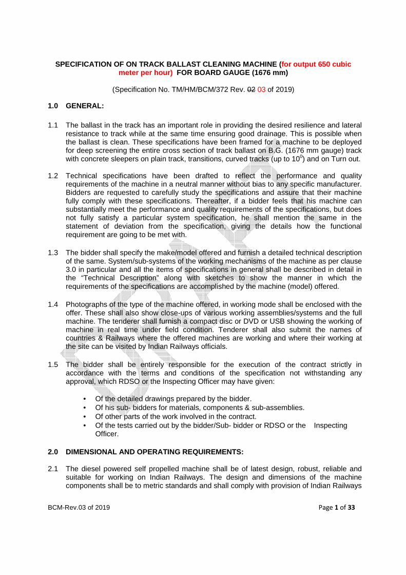
SPECIFICATION OF ON TRACK BALLAST CLEANING MACHINE (for output 650 cubic meter per hour) FOR BOARD GAUGE (1676 mm)
(Specification No. TM/HM/BCM/372 Rev. 02 03 of 2019)
1.0 GENERAL:
1.1 The ballast in the track has an important role in providing the desired resilience and lateral resistance to track while at the same time ensuring good drainage. This is possible when the ballast is clean. These specifications have been framed for a machine to be deployed for deep screening the entire cross section of track ballast on B.G. (1676 mm gauge) track with concrete sleepers on plain track, transitions, curved tracks (up to 100) and on Turn out.
1.2 Technical specifications have been drafted to reflect the performance and quality requirements of the machine in a neutral manner without bias to any specific manufacturer. Bidders are requested to carefully study the specifications and assure that their machine fully comply with these specifications. Thereafter, if a bidder feels that his machine can substantially meet the performance and quality requirements of the specifications, but does not fully satisfy a particular system specification, he shall mention the same in the statement of deviation from the specification, giving the details how the functional requirement are going to be met with.
1.3 The bidder shall specify the make/model offered and furnish a detailed technical description
of the same. System/sub-systems of the working mechanisms of the machine as per clause 3.0 in particular and all the items of specifications in general shall be described in detail in the “Technical Description” along with sketches to show the manner in which the requirements of the specifications are accomplished by the machine (model) offered.
1.4 Photographs of the type of the machine offered, in working mode shall be enclosed with the
offer. These shall also show close-ups of various working assemblies/systems and the full machine. The tenderer shall furnish a compact disc or DVD or USB showing the working of machine in real time under field condition. Tenderer shall also submit the names of countries & Railways where the offered machines are working and where their working at the site can be visited by Indian Railways officials.
1.5 The bidder shall be entirely responsible for the execution of the contract strictly in
accordance with the terms and conditions of the specification not withstanding any approval, which RDSO or the Inspecting Officer may have given:
• Of the detailed drawings prepared by the bidder. • Of his sub- bidders for materials, components & sub-assemblies. • Of other parts of the work involved in the contract. • Of the tests carried out by the bidder/Sub- bidder or RDSO or the Inspecting
Officer.
2.0 DIMENSIONAL AND OPERATING REQUIREMENTS:
2.1 The diesel powered self propelled machine shall be of latest design, robust, reliable and suitable for working on Indian Railways. The design and dimensions of the machine components shall be to metric standards and shall comply with provision of Indian Railways
BCM-Rev.03 of 2019 Page 2 of 33
Schedule of Dimensions–1676 mm gauge (BG), revised, 2004 with latest corrigendum and up to date correction slips issued. Quality assurance during manufacturing of the machine shall be according to ISO-9001. The welding standard followed for manufacturing of machine shall conform to ISO: 3834, EN: 15085 or any other equivalent standard for welding Railways vehicles and components. The manufacturer shall specify the standard followed and certify that it meets the welding standard mentioned above. The machine shall be suitable for working on straight, transition, curved track (up to 10°) and on Turn out broad gauge (1676 mm) of Indian Railways.
2.2 The profile of the machine longitudinally and in cross section during transfer as self propelled vehicle or towed in train formation shall be within the maximum moving dimensions shown in the Indian Railways Standard BG schedule of Dimensions(metric)- 2004 print with the latest corrigendum and up to date correction slips issued. The maximum moving dimensions are enclosed in Annexure-I. The tenderer shall provide sketches of the machine in plan and shall give calculations for moving dimensions on 10° curve to show the extent of lateral shift at the ends, centre and any other relevant cross section and to show that the machine does not cause infringement while moving on a 10° curve at any cross section.
2.3 In the past Indian Railways have condoned certain infringements to the Indian Railways
Schedule of Dimensions-1676 mm gauge (BG), revised, 2004 of such dimensions as Rigid wheel Base, Length of stocks, Distance apart of bogie centres and maximum height of floor above Rail level in certain track machines after due consideration of their design features vis-à-vis safety and operation requirements of Indian Railways. However, condonation of an infringement in another track machine in the past does not by itself entitle the manufacturer to assume acceptance of the same in other track machines by Indian Railways. Where an infringement to Indian Railways Standard BG schedule of Dimensions (metric)-2004 is considered necessary by the manufacturer as intrinsic to the design of the machine for meeting the work performance requirements laid down in this specification while meeting the safety and operational requirements of Indian Railways, the condonation of the same may be permitted by Indian Railways. However, only those infringements which are acceptable shall be permitted.
2.4 Adequate clearance shall be allowed so that no component infringes the minimum vertical
clearance of 102 mm from rail level while travelling on track up to condemnation limit of wheel.
2.5 Wherever applicable axle load shall be lesser than 20.32 tonnes with minimum axle
spacing of 1.83 m while moving on track. Load per metre shall not exceed 7.67 tonnes. Axle loads up to 22.82 tonnes and lower axle spacing may be permitted, provided the load combinations do not cause excessive stresses in the track and bridges of Indian Railways. Stresses in the track and bridges shall be calculated by IR/RDSO based on design data submitted by the firm as per Annexure–VIII and decision of IR/RDSO shall be final in this regards.
2.6 It shall have a minimum wheel diameter of 914 mm (new wheel profile). However, lesser
diameter up to 730 mm (new wheel profile) can also be considered, provided it meets the criteria condition laid down in Clause 2.4 at its condemnation limit and also rail wheel contact stresses for 72 UTS rails are within permissible limits. Forged wheels to Indian Railways profile shall be provided on the machine. It is desirable that 50 mm margin between new and permitted worn wheel diameter are available, however this should not be

BCM-Rev.03 of 2019 Page 3 of 33
less than 20 mm. The worn out wheel diameter (condemning worn out diameter) based on the criteria of rail wheel contact stresses for various maximum axle loads are as under:
Maximum Axle load (tonnes) Minimum worn out wheel diameter (mm) 22.82 908.00 22.00 878.00 21.50 860.00 21.00 841.00 20.32 816.00 20.00 805.00 19.50 787.00 19.00 768.00 18.50 750.00 18.00 732.00 17.50 713.00 17.42 710.00
Permitted worn out wheel diameter should be specified by the manufacturer. The diameter of wheel for assessment of permitted axle load will be the worn out wheel diameter.
2.7 The new wheel profile in the machine shall be as per Indian Railways standard drawing attached as Annexure- III, which is titled as “WORN WHEEL PROFILE”.
2.8 Wheels shall be conforming to Indian Railways Standard R-19/93 or European Standard EN13262 or any other equivalent standard (for product requirement) and design shall duly conform to European Standard EN 13979 or other equivalent standard. The supplier shall submit detailed design calculation along with material parameters at the time of supply of the machine.
2.9 The non-powered axles shall be conforming to Indian Railways Standard R-16/95 or
European Standard EN 13261(EA1N) or any other equivalent standard. The supplier shall submit detailed design calculation along with material parameters at the time of supply of the machine.
2.10 The powered axles shall be conforming to Indian Railways Standard R-43/92 or European
Standard EN 13261(EA4T) or any other equivalent standard (for product requirement). The design shall conform to EN: 13104 or any other equivalent standard. The supplier shall submit detailed design calculation along with material parameters at the time of supply of the machine.
2.11 It shall be capable of negotiating curves up to 10o
curvature (175 m radius), super elevation up to 185 mm and gradients up to 3% in travel mode. The supplier shall specify the minimum attainable speed under the above limiting conditions which in any case shall not be less than 40 kmph.
2.12 It shall be capable of continuous operation during the varying atmospheric and climatic
conditions occurring throughout the year in India. The range of climatic conditions is as follows:-
BCM-Rev.03 of 2019 Page 4 of 33
Ambient temperature : -50 to 55°C
Altitude : up to 1750 m above mean sea level Humidity : Up to 100% Maximum rail temp : 70o
C All the system components on the machine, which are vulnerable to moisture ingress and adversely affected during rains, shall be covered by roof or suitable arrangement so that the machine is able to work continuously even during rains.
2.13 During transfer from one station to another, it shall be capable of travelling on its own at a speed of 80 kmph and at a speed of 100 kmph when hauled in a train formation as last vehicle. Since the machine is likely to cover long distances on its own power, the travel drive system should be robust to sustain these requirements during the life of the machine without significant break down/failure. The machine shall be capable of hauling an 8-wheeler coach/wagon (gross weight 90 tonnes approximately) at a maximum speed of not less than 50 kmph. It shall be able to negotiate sharpest gradient up to 1 in 33 prevailing on Indian Railways.
2.14 It shall be capable of working and travelling without requiring power block in electrified
sections. On Indian Railways, 25 KV or 2x25 KV AC power supply is used for traction through an overhead wire at 5500 mm above rail level. On bridges and tunnels, the height is restricted to 4800 mm.
2.15 While working on double/multiple line sections, it shall not infringe the adjoining track and it
shall be possible to permit trains at full speed on that track. Minimum spacing of track is 4265 mm centre to centre.
2.16 The machine or its any part shall not infringe the adjoining track as per Indian Railways
Schedule of Dimensions 1676 mm gauge (BG), revised-2004 with the latest corrigendum and up to date correction slips issued, while opening and closing of work.
2.17 It shall be possible to drive the machine in both directions at the same speed. Driving cabin
shall be at both end of the machine for this purpose.
2.18 The machine shall be self propelled bogie type vehicle with minimum four axles (two bogies).
3.0 WORKING MECHANISM
3.1 The machine shall be a combination of excavation unit, screening unit, waste disposal unit
and screened ballast distribution unit. The machine shall be capable of working on all types of track structures including long welded rails of 60Kg./52Kg./90R on concrete on plain track as well as T/outs (1 in 8.5 to 1 in 16) as per IRS layout.
3.2 Since the machine is to work in dusty environments, all the components including gear boxes, bearings, drive motors, pumps, electric and electronic control shall be of robust design, shielded and sealed from the dust and spill over ballast pieces. Suitable protections /covers must be provided so that these components do not fail prematurely. The various assemblies and the machine as a whole should provide adequate safety to workmen
BCM-Rev.03 of 2019 Page 5 of 33
working close-by in connection with the machine operations. The necessary safety equipments shall form a part of the machine tools and plants. The tenderer should indicate these items in their offer.
3.3 The machine shall be capable of excavating ballast bed up to a depth of 900 mm below the
rail top and entire width of ballast section. The width of ballast section from track centre is 2525 mm to 2851 mm for tangent track and 2675 mm to 3009 mm for curved track. The width of ballast section from track centre is 4800 mm for Turnouts. While working it should be possible to increase the width of cut in steps so as not to infringe the schedule of dimensions at any location and at the same time, cover the entire cross section of turnout track at the longest sleeper in the crossing area. The machine shall be so designed that whenever extension pieces are added to cutter chain, amount of increased width of the cutter chain shall also be available symmetrically at each side of sleeper i.e., half of the increased width of cutter chain shall be available at either side of sleeper end when working on tangent track. There shall be provision of limiting the opening of trough to avoid infringement of schedule of dimension of adjacent track as required by Indian Railways.
3.4 The machine shall be able to deep screen both left hand/right hand turnouts when
approached from either direction, i.e., from the switch or the crossing side, depending upon the site conditions. No turning of the machine shall be required for this purpose. While fixing the extension pieces to increase the width of deep screening, sufficient arrangement based on manufacturer design shall be met in such a way that there is no sag in the assembly and does not disturb the alignment/straightness of deep screening.
3.5 The lifting and slewing devices of the machine shall be capable of handling long welded rails on wider/normal PSC, so that it may be possible to adjust the excavation depth and carry out slewing to avoid obstacles such as station platforms. While working on the plain track, it shall be capable of lifting the track ahead of excavating mechanism up to at least 100 mm and temporarily slew the track by at least up to 200 mm.
3.6 The excavation depth shall be adjustable to suit the requirements of sites. The ballast shall
be excavated up to the desired depth in one working pass. It shall be ensured that the formation or its any portion shall not be cut/damaged by the cutter bar/excavating chain during course of excavation.
3.7 The machine while working shall, without slewing the track be able to bypass the
foundations of the OHE masts. To achieve this, it shall be possible to retract the cutting mechanism towards track centre at OHE mast location and bring it back to cover the full ballast section after the OHE mast foundation is cleared. A typical ballast section and location of mast foundation is enclosed along with as Annexure-IV. Suitable sketches of the relevant machine assemblies shall be furnished to clarify this aspect.
3.8 The machine shall be able to provide straight and continuous cross slope from level to 1 in 30 or steeper from one end to the other towards either side at the cutting level for drainage purpose. A system shall be provided in the machine for measurement and automatic control of excavating depth and inclination of cross slope of formation. While setting the machine for cross slope separate continuous indication shall be provided in the working cabin to the operator of the machine for cross slope actually been provided. This will

BCM-Rev.03 of 2019 Page 6 of 33
ensure that during deep screening, a uniform and accurate cross slope is provided by the machine. To achieve this, it is desirable that the excavation unit excavates the ballast from the entire cross section in one continuous cross slope without any discontinuity. Suitable sketches of the relevant machine assemblies should be furnished to clarify this aspect.
3.9 The screening units shall be capable of screening the excavated ballast through a series of
screens (three layer of different size sieve with minimum specific screen output of 24 m3/h/m2). The screened ballast sizes shall be 65 mm maximum and 25 mm minimum. The screening units shall remain in horizontal position laterally, even when working in curves with super elevation up to 185 mm. The machine shall have adequate sieving capacity to match the output requirement with satisfactory quality of screening as given in clause 3.19.
3.10 The waste conveyor belt shall be slewable minimum 700
to left and 700 to right of center line
of track. It shall be possible to dispose off the spoil directly beyond the cess at a distance of not less than 7 m from the centre of track on either side of the machine. The conveyor system for spoil shall be such that no spoil falls on cleaned track. This feature is particularly important in the context of electrified sections where the spoil conveyor is required to swing back near every mast of overhead wire or signal post and such other features in the yard. Muck at such locations should be unloaded to the front or yet to be deep screened track. There shall be provision of limiting the slew of waste conveyor belt to avoid infringement of schedule of dimension of adjacent track as required by Indian Railways.
3.11 The tenderer shall provide a suitable safety mechanism to ensure that the spoil conveyor
does not hit the OHE mast or a signal post. Also suitable cut off system shall be provided so that even if the conveyor belt hits the OHE mast or signal post due to bad operation of the machine like non withdrawal of the muck conveyor in time to bypass the mast or signal post etc. the machine is immediately stopped and no damage is caused to the machine and the OHE/signal post.
3.12 Loading of spoil into a Muck Disposal Unit attached to the machine shall also be possible,
when required, while working in yards, multiple lines, tunnels or cuttings etc. Machine during working mode shall be capable of hauling/pushing Muck Disposal Unit attached with the machine. Maximum trailing load of Muck Disposal Units is 800 tonnes approximately. The Muck Disposal Unit shall be air braked vehicles.
3.13 A combination of swivelling side conveyors, chutes and ballast plough shall be provided for
distribution of cleaned ballast in the track on the shoulders/centre of track/tamping zones or in any desired combination and closely behind the excavating mechanism. While deep screening turnouts, it shall be possible to distribute the clean ballast over the entire turnout width. There shall be suitable mechanism to ensure that there is no heaping up of ballast or too short deposit of screened ballast at the beginning or at the end of the work or during any stoppage of the machine. It should be possible to control the ballast distribution across the whole cross section from the operator’s cabin.
3.14 The machine after putting the cleaned ballast into the track shall profile the ballast and
clear the ballast from the top of rail, sleepers and fastenings by using suitable mechanism. The profiling unit shall also be capable of pulling the cess ballast into the tamping zone.
BCM-Rev.03 of 2019 Page 7 of 33
3.15 Various mechanisms of the machine shall be so designed that the ballast pieces do not scatter. The ballast conveyors at locations approachable by workmen close by shall be enclosed in safety trough/cages for the safety of the men.
3.16 After carrying out the work, the machine shall leave the track in a condition to permit the
passage of the trains up to 40 kmph. Suitable mechanisms for grading of screened ballast bed before lowering of the track shall be provided for this purpose.
3.17 Time required for starting the excavation and screening of ballast after arrival of the machine at the site of work, together with the time of winding up the machine and starting back from the site after the stoppage of the screening shall be less than 20 minutes. This does not include the time required for one time insertion of any cutting device in the track which is left behind after completion of days work. A suitable hydraulic/pneumatic locking device for quick attachment/detachment of excavating unit or any other type mechanism may be provided to achieve minimum possible time for starting and closing the screening work during block.
3.18 The machine shall be capable of cleaning, grading, and profiling a minimum 550 650 cubic
meter of ballast on plain track in an hour of working including hard, encrusted and cracked ballast.
3.19 The efficiency of screening shall be judged by collecting four samples of the screened
material as it falls from the machine. Not more than 4% of screened ballast by volume shall pass through a 25 mm Sieve (ISI Standard). Four samples of the muck disposed by BCM shall also be collected. This muck shall not contain more than 10% of ballast of size between 25 mm to 65 mm. The size and gradation of new ballast being used in Indian Railways is as given below:
a. Retained on 65 mm square mesh sieve 5% max.
b. Retained on 40 mm square mesh sieve 40%-60% (for machine crushed)
c. Retained on 20 mm square mesh sieve Not less than 98% (for machine
crushed) Not less than 95% (for hand broken)
The ballast with time gets crushed and at the time of screening will be of different size and grade.
3.20 The machine shall be provided with one additional industrial quality heavy duty portable computer (Laptop) for keeping record of overall aspects of working, spares management and reporting. The detailed specifications of the laptop are enclosed as Annexure-V.
3.21 All work units like excavator chain, lifting, slewing and screening units shall be preferably hydraulically or pneumatically driven.
3.22 The machine shall be equipped with a centralized computer based control and monitoring
system which shall monitor the health of machine working system such as engine (lubricating oil pressure, temperature, rpm etc.), hydraulics (hydraulic pressure in different
BCM-Rev.03 of 2019 Page 8 of 33
units, temperature, oil level in tank etc.), pneumatic (pressure of different units), electrical (charging/discharging rate, voltage etc.). All these data should be displayed on a monitor installed in working cabin and there shall be facility to store these data for 100 engine running hours. Minimum storage of 500 GB shall be available for this purpose. Arrangement for providing 3G/4G internet connection for sending data in soft format directly from the computer shall also be available.
3.23 In case of failure of the working of excavator chain, waste disposal conveyor or any other working unit that may infringe the track, there shall be an arrangement for retracting these units mechanically by any equipment like tirfor/chain pulley etc. Any other alternative arrangement for mechanically retracting the units in such failures should also be provided.
4.0 DIESEL ENGINE 4.1 The machine shall be powered by diesel engine(s) preferably indigenous with proven
record of service in tropical countries with wide service network in India. Robust construction and low maintenance cost are of particular importance. Adequate allowance shall be made for de-rating of diesel engine under the most adverse climatic conditions mentioned in this specification elsewhere.
4.2 High speed diesel oil to Indian Standard Specification shall be normally used. A minimum fuel capacity sufficient for continuous operation for 8 hours but not 1400 liters shall be provided.
4.3 Sight glass type fuel measuring gauge preferably of full height shall be provided on the fuel
tank.
4.4 For starting the engine, storage batteries of well known indigenous make with wide service network in India shall be provided. The engine shall normally be push/pull button start type or key type.
4.5 Since the engine has to work outdoor under extreme dusty conditions, the air intake system
shall be designed suitably so as not to allow dust through air intake system.
4.6 There is a likelihood of dust deposition over the engine body and surrounding area over the lubricants spill-over. These locations shall be easy to accessible for daily cleaning and routine maintenance. In case, air cooled engines are proposed by the supplier, maintenance equipment for cleaning and maintenance of the air cooling fins shall be provided by the supplier along with the machine.
4.7 The engine parameter monitoring gauges like temperature, rpm, and lubricant oil pressure
shall be direct reading type mounted on the engine backed up by electrical/mechanical gauges in the operator’s cabin showing the absolute readings along with safe limits suitably coloured. There shall be audio visual warning (safety mechanism) to the operators in case of any of these parameters exceeding the safe limit and engine will shut down automatically.
4.8 Suitable and rugged mechanism shall be provided to start the prime mover at no
load/minimum load and gradual loading after the start of the prime mover. A fail safe clutch mechanism, if required, may be provided to meet this requirement. The engine power take

BCM-Rev.03 of 2019 Page 9 of 33
off shall be coupled to the main gearbox through a flexible coupling/cardon shaft (propeller shaft). The engine shall be mounted on suitable anti vibration mountings.
4.9 The tenderer shall furnish the information regarding make and model of the engine
proposed to be used and details of agency which will provide after sales service support and availability of spares in India, details of diesel engine and its controls to assess its conformity with the engines already operating on track machines on Indian Railways. If the machine design incorporates an engine, not already operating with the purchaser, the model of the engine is liable for change as per the technical requirements and the maintenance logistics with the purchaser after technical negotiations with the supplier. Nothing extra shall be payable on this account.
4.10 The engine shall have Electronic Control Module (ECM) or similar arrangement for taking
out operating parameters on real time basis such as RPM, load, fuel consumption, temperature, pressure and diagnostic data as well as trip and historical data. These data shall be displayed and stored on a centralized computer and monitoring system as mentioned in para 3.22 above. It shall also be possible to transfer these data on USB device through the centralised computer based control.
4.11 In order to adhere to pollution control norms, the diesel engine should be electronically
controlled emmissionized engine with minimum compliance of tier 2 stage.
4.12 The engine shall be enclosed in a weather protective, sound and dust resistant enclosure to minimize engine noise and to prevent oozing out of oil spills etc. from engine area to the adjacent machine components, hoses, electrical cables fittings as a protection against fire. All doors on the enclosure shall be strategically located in areas as to allow ease of maintenance of the engine and allow good access to and visibility of instruments, controls, engine gauges, etc. Sufficient louvers shall be provided to allow the total engine cooling air requirements used in this application.
5.0 DRIVE MECHANISM
5.1 The machine shall be provided with an efficient traction drive system for traction during the
operation. The machine’s driving system shall be through hydrostatically coupled power/transmission with shift arrangement capable of achieving full speeds in travel mode in both the directions. The system should be so designed that all the driving wheels work in synchronization and there is no slippage/skidding of the wheels during the work drive. The driving mechanism for travel drive shall be rugged to perform satisfactorily during the life cycle of the machine.
5.2 The driving mechanism, in working mode, shall be adequately designed to handle the
acceleration and braking forces. A suitable synchronization circuit to control the synchronization of lifting/lining/screening process with the machine drive/braking system in working mode shall be provided to prevent any damage to the machine systems on account of non-synchronization.
5.3 Suitable differential systems may be provided between coupled wheels on the same bogie.
5.4 Suitable flow divider/throttling arrangement may be provided to equalize the tractive effort
amongst different bogies.
BCM-Rev.03 of 2019 Page 10 of 33
5.5 The supplier shall provide the necessary technical details including circuit diagrams and
detailed specifications of all electronic/electrical, hydraulic & pneumatic parts to confirm the above requirements.
5.6 Adequate gauges to monitor driving and working performance of machine shall be provided
in working and driving cabins near operator’s seat and solenoid valves shall be provided near linkage assembly for indication, flow control and carrying out necessary adjustment in the field.
5.7 To the extent possible hydraulic and pneumatic component/assembly shall be fixed at
suitable location preferably on the side frame of the machine so as to avoid the need of going on top of the machine for day-today maintenance schedules.
5.8 The pneumatic circuit shall be provided with air dryer and air lubricator for the smooth
working of pneumatic components.
5.9 The machine shall be equipped with adequate safety circuit such that if any unit/part which may endanger the safety if unlocked, the machine shall not move during run drive. The indication of locking and unlocking of all units should display in the cabin.
5.10 Onboard system for online filtration and monitoring the quality of hydraulic oil in hydraulic
circuit should be provided. The gauge shall clearly indicate that the hydraulic oil is contaminated beyond the permissible limits and requires immediate replacement.
6.0 COOLING SYSTEM 6.1 The cooling system shall be efficient and designed for a maximum ambient temperature of
55°C. Supplier shall note that the machine shall be working under extreme dusty conditions and the cooling mechanism shall be maintainable under these conditions.
6.2 Adequate heat transfer arrangement for the hydraulic system shall be designed and provided so that under extreme heat conditions as mentioned in clause 2.12 above, the system oil temperature does not go beyond the range specified by the supplier.
7.0 BRAKES
7.1 The machine shall be fitted with the compressed air brake system which shall apply brake
equally on all wheels and provision shall be made to connect air brake system of the machine to that of coach/wagon/muck disposal unit hauled by the machine. Fail safe braking mechanism system shall be provided so that in case of any failure of brake there shall be arrangement of automatic application of brake. The pneumatic parking brake shall also be spring loaded so that in case of drop in pneumatic pressure below certain value the brake will be applied automatically. The brakes shall be protected from ingress of water, grease, oil or other substances which may have an adverse effect on them. The brake shoe lining shall be suitable for high ambient temperature of 55°C. The force required for operating the brake shall not exceed 10 kg at the handle while applying by hand and 20 kg on the pedal, when applied by foot. Mechanical brakes shall also be provided in addition for use as parking.
BCM-Rev.03 of 2019 Page 11 of 33
7.2 Machine shall be equipped with suitable arrangement of braking so that while attached in train formation as last vehicle, machine can be braked by traction vehicle having compressed air braking system. In addition the machine shall be equipped with suitable air brake system in the driving cabins so that the attached wagon or coach while being hauled by the machine can be braked.
7.3 There shall be provision of emergency brake application using the compressed air in the
machine either travelling alone or coupled with the coach/wagons/MDU, in addition to the normal braking system of the machine. The emergency braking distance (EBD) of the machine on the Indian Railways track at the maximum designed speed on a level track shall not be more than 600 m. In this regard necessary design calculations for the braking effort and EBD at the maximum design speed of the machine on level track & at falling grade of 1 in 33 should be provided by the supplier. Brake design details are to be submitted as per Annexure VI.
7.4 Clearly visible brake lights shall be provided at both the ends of the machine, which will be
automatically operated when brake is applied and switched off when brake is released. This will be required to alert the operator of machine following this machine when the machines are working in groups.
8.0 HORN, HOOTER AND SAFETY SWITCHES
8.1 The machine shall be provided with dual tone (low tone & high tone) electric/pneumatic
horns facing outwards at each end of the machine at suitable locations for use during travelling to warn the workmen of any impending danger. Control shall be provided in close proximity to the driver permitting the driver to operate either horn individually or both horns simultaneously. The horns shall be distinctly audible from a distance of at-least 400 m from the machine and shall produce sound of 120-125 dB at a distance of 5 m from horn (source of sound). The higher tone horn shall have fundamental frequency of 370 ±15 hertz. These horns shall be operated by means of push buttons provided in the cabins.
8.2 Adequate numbers of safety stop switches shall be provided all around so that in case of any danger to worker as well as hitting of any obstructions like signal cable, joggle fish plate, OHE/signal post etc. by any screening unit during work, so that the operator can be warned or the machine can be stopped immediately.
8.3 Safety equipment like jack, pullers, terfor and other such equipments specific to the
machine for restoring failed units of the machine during working shall be provided on the machine.
8.4 Machine shall be provided with emergency backup system to wind up the machine in the
event of failure of prime mover or power transmission system of the machine. The emergency backup system shall be able to be operated manually also.
8.5 Pneumatically/electrically operated hooters capable of producing intensity of sound
between 105-110 dB at a distance of 5 m (when measured in still air in a closed room) and variation in intensity of sound shall not be more than 5 dB. The hooter shall be provided facing outwards at each end of the machine at suitable locations, operated by means of push buttons provided in the cabins to warn the staff working on/around the machine about approaching train on adjoining track. Additionally switches for such pneumatic hooter shall
BCM-Rev.03 of 2019 Page 12 of 33
be provided in the machine frame and near the both side exit gates so that it can be operated by staff present at work site near the machine. The hooter shall also be operated by remote switch at a distance of at least 300 m from the hooter.
8.6 In addition, separate electric horns with push bottom type switches shall be provided at
suitable locations in all cabin(s) and on machine body for communication between the machine staff about infringement/malfunctioning or any other trouble.
9.0 HOOKS AND BUFFERS
9.1 The machine shall be fitted with transition coupling as per specification no.
RDSO/2009/CG-22 with latest revision along with side buffers to RDSO drawing no. RDSO/SK-98145 with latest alteration on both ends for coupling it with coach or other vehicles and for attachment with muck disposal unit, coach, locomotives and wagon while running in train formation as last vehicle.
10.0 HEAD LIGHT, FLASHER LIGHT, MARKER LIGHT AND OT HER LIGHTING ARRANGEMENTS
10.1 The electrical equipment to be provided shall conform to relevant standard specifications and shall be suitable for Indian climatic conditions. The machine shall be equipped with twin beam LED headlight assembly conforming to RDSO specification no. RDSO/2017/EL/SPEC/0134 (Rev-0) with latest amendment to ensuring a light intensity of 3.2 lux at ground level at track centre at a distance of 305 m away on a clear dark night, at each end and with two front and rear parking lights, which can be switched to red or white according to the direction of the travel. Powerful swivelling floodlights shall also be provided to illuminate the working area sufficiently bright for efficient working during night. In addition minimum eight power point locations (24 volt DC/15 amp socket) shall be provided on outside frame of the machine two in front, two in rear and two on both sides for providing lighting arrangements during night working. Specification for DC-DC converter for electric loco/diesel electric loco no. ELRS/SPEC/DC-DC converter/0021, (rev-1, Sept’2004 or latest).
10.2 The amber colour LED based flasher lights producing not less than 500 lux at 1 m and 55 lux at 3 m in line measurement in axial direction from flasher light to RDSO Spec No. ELRS/SPEC/LFL/0017 (Rev-1) of Sept-2004 or latest shall be provided at both ends in the machine to give indication to the train arriving on other line about any impending danger.
10.3 The Ballast cleaning machine shall be provided with Marker light to RDSO specification no.
ELRS/SPEC/PR/0022, (Rev-1) October’2004 or latest.
11.0 CHASSIS AND UNDERFRAME
11.1 The chassis shall be fabricated from standard welded steel sections and of steel sheets, so as to permit transportation of the machine in train formation without endangering safety of the train. The under-frame shall be constructed with rolled steel section and/or plates shall be designed to withstand a horizontal squeeze load of 102 t at CBC rear stops or 51 t at each buffing point without any permanent distortion. The under-frame shall be sufficiently robust for safe travel of the machine in train formation and not necessarily as the last vehicle.
12.0 SUSPENSION SYSTEM
BCM-Rev.03 of 2019 Page 13 of 33
12.1 The suspension system shall be preferably of two-stage type with suitable spring and
damping arrangement. Spring for primary and secondary suspension shall be designed to cater for actual service conditions. Effective measure shall be adopted to minimize the weight transfer while starting, stopping and during runs.
13.0 CABINS
13.1 The machine shall be equipped with fully enclosed, sound and heat insulated cabins with safety glass window at both the ends. In view of the high ambient temperature prevailing in India, special attention should be paid to free circulation of air and ventilation in the driver’s cabin. It shall be possible to have a clear view of the track ahead while driving the machine in both the directions from the cabins at either ends. The cabin layout shall be such that the operating staff has full view on both the sides before leaving the machine, to avoid any danger to them from trains on the adjacent tracks. Additional driver’s cabin shall be provided, if the view, while driving is not clear for safe travel in both directions.
13.2 The working cabin of the machine shall be air-conditioned for dust free atmosphere. The
air-conditioning provided shall be of robust industrial design capable of operating in highly dust laden environment. The air-conditioning units shall not be roof mounted and under-frame mounted for safety and maintenance purpose. However the electronic equipment shall be so designed that they shall be able to work without air-conditioning under the climatic conditions as described in clause 2.12 above.
13.3 The gauges, panels and controls shall be suitably located in the operator’s cabin so that
they can be observed by the operator without undue fatigue.
13.4 The operator’s cabin shall be ergonomically designed to have easy access to all the controls. The operator shall have a full view of the working area from the operating seat to have a full control over the work.
13.5 Screen wiper preferably operated by compressed air or electrically operated shall be
provided on the wind screens.
13.6 Suitable number of fire extinguisher (dry chemical type) shall be provided in all the cabins. The chemicals used for extinguishing fire by such fire extinguishers shall not chemically react with electronic equipment/components, PCBs, cables etc.
13.7 The machine shall be provided with well designed space for keeping the tools and spares
required for onsite repair of the machine to attend the breakdowns and other working requirements.
13.8 Necessary inter-communication system shall be provided inter-connecting all the cabins
and shall be so oriented that the operator, seating on the seat of either cabins/working cabin, can easily operate/hear distinctly the conversation.
13.9 The machine shall be equipped with speed indicator and recording equipment of range
between 0-120 kmph for recording the speed of the machine in real time basis. The equipment shall conform to RDSO specification no. MP-0-0.3700-07, Rev-07, Aug’17 or latest. The recorded data shall be retrievable on computer through memory card/pen drive.
BCM-Rev.03 of 2019 Page 14 of 33
It shall be provided in the driving cabin at suitable place and recording system shall have sufficient memory to keep the speed record of minimum 15 days which should always be stored for retrieving as per requirement.
13.10 The electric supply in the cabin for operation of electrical instruments, gauges etc. shall
not be more than of 110 V.
14.0 TOOLS AND INSTRUCTIONS MANUALS
14.1 Each machine shall be supplied with a complete kit of tools required by the operator in
emergency and for normal working of the machine. The tenderer shall along with his offer submit the list of tools to be supplied along with each machine. The list of tools to be provided shall also include all tools necessary for maintenance and repair of the entire machine including specialized equipment. All special tools shall be listed and catalogued illustrating the method of application. The tenderer shall along with his offer submit the list of tools to be supplied along with each machine. The list can be modified to suit the purchaser’s requirement, while examining the offer.
14.2 Detailed operating manual, maintenance, service manual and user manual indicating capabilities of machine shall be specifically prepared in English language and four hard & soft copies of these shall be supplied with each machine.
14.3 The manufacturer shall also supply circuit diagrams in hard and soft copies of electrical,
electronic, hydraulic, and pneumatic circuits used on the machine. Trouble shooting diagram/table shall also be supplied. In additions, the supplier shall provide dimensional drawings with material description of items like rubber seals, washers, springs, bushes, metallic pins etc. and main features such as type and discharge etc. of items like hydraulic pumps, motors and such other bought out components/assemblies shall be furnished by the tenderer. These shall be specially prepared in English language and four in hard and soft copies of these shall be provided with each machine.
14.4 While offering the machine for first inspection, the supplier shall submit one copy of
complete technical literature in English language including operation, service and field maintenance manuals/instructions, complete electrical, hydraulic and pneumatic circuit diagrams, trouble shooting charts, components drawings/description and other relevant technical details for keeping as a reference document for the inspecting officer.
14.5 The tenderer shall along with his offer, submit the list of tools, manuals, circuit diagrams
and other technical literature/drawings in English language to be supplied along with each machine as above, for operation, servicing, maintenance, assembly overhauling, periodic overhauling and troubleshooting guides/manuals. The list can be modified to suit the purchaser’s requirement, while examining the offer.
14.6 One portable diesel operated D.C. welding plant (with the provision of auxiliary output of
minimum 2.5 KW, 230 V AC for lighting) of reputed make (preferably made in India) with a minimum 5 KVA capacity capable of welding up to 5 mm (dia) electrode at 60% duty cycle shall be supplied. Sufficient cable or lead shall be provided with the machine of welding plant for day to day repairing of machine and its wearing parts. The diesel tank capacity shall be not less than 15 liters.
BCM-Rev.03 of 2019 Page 15 of 33
14.7 One set of all the manuals and diagrams in hard and soft copies prepared in English
language shall also be sent to the Principal/IRTMTC, Allahabad, one set to ED/TMM, RDSO, Lucknow, one set to DTK (MC)/Railway Board and one set to Director/IRICEN/Pune along with supply of first machine of similar group. In case, there is any subsequent amendment in above documents based on field performance, the amendment/amended documents shall also be sent to above mentioned authorities.
14.8 The firm shall provide detailed technical drawings and specifications of wheels and axles
used in the machine. The above details shall be provided in four sets with each machine.
14.9 A draft copy of all documents to be supplied with the machine shall be sent 3 months in advance of inspection of the first machine to RDSO for their review regarding adequacy and manner of detailing. Necessary modifications and further detailing as per RDSO’s comments shall be carried out and compliance shall be reported to RDSO as well as the Inspecting officer of the first machine.
15.0 SPARE PARTS
15.1 The expected life of the components/spare parts shall be advised along with their
condemning limits. The machines shall be supplied with necessary spare parts for the operation and maintenance of the machine for a period of two years, i.e., working for about 2000 hours. The spare parts required shall be detailed in a separate list indicating description, part number, quantity and whether imported or indigenous.
15.2 The manufacturer shall be responsible for the subsequent availability of spare parts to ensure trouble free service for the life of the machine (20 years). It is preferred that the spares shall be stored in India and will be available at short notice say maximum within a month.
15.3 For indigenous parts and bought out components and assemblies, the source (original
equipment manufacturer’s reference and part no.) and other relevant technical details shall be supplied while offering the first machine for inspection.
16.0 OPTIONAL EQUIPMENT 16.1 Tenderer is expected to quote for optional equipment if any separately for each item giving
the advantages/functions of such optional equipment. Tenderer shall also indicate whether such equipment are already in use on machine elsewhere indicating the user Railways system.
17.0 MAKER’S TEST CERTIFICATE 17.1 Copies of maker’s certificate guaranteeing the performance of the machines shall be
supplied in duplicate along with the delivery of each machine.
18.0 OPERATORS
18.1 The number of operators and allied staff for working of the machines under normal condition shall be indicated, specifying their duties and minimum qualifications.
BCM-Rev.03 of 2019 Page 16 of 33
19.0 INSPECTION OF THE MACHINE 19.1 While inspecting the machine before dispatch from the supplier’s premises, the inspecting
officer shall verify the conformity of the machine with respect to individual specification as above. The machine’s conformity/non-conformity issue in respect to each item shall be jointly recorded before issue of the inspection certificate and approval for dispatch of the machine as per Annexure–VII enclosed.
19.2 Following arrangements shall be made by the supplier/Manufacturer at the inspection premises for carrying out inspection of the machine by inspecting officials:
• Machine to be stabled on straight & level BG track. The length of the track shall be at
least 10 m more than buffer to buffer length of machine.
• In order to check maximum moving dimensions in cross section, a sturdy frame of Indian Railways max moving dimensions shall be provided by the manufacturer and passed over the machine holding it perpendicular to track, centre aligned with track centre. Adequate arrangements shall be made to the satisfaction of inspecting official.
19.3 The following documents shall be provided to the Inspecting Officer at least 30 days in
advance of the date of inspection.
i) One copy of complete technical literature mentioned in clause 14, in English language, including operation, service and field maintenance manuals/instructions and complete electrical, hydraulic and pneumatic circuit diagrams, trouble shooting charts, component drawings/description and other relevant technical details as a reference documents in soft & hard copies for the inspecting officer.
ii) Cross section of the machine super imposed on Indian Railways maximum moving dimensions envelope shall be provided to inspecting officer (IO) in advance.
iii) Clause by clause comments of the manufacturer to be sent to Inspecting Officer (IO)
in advance for his review. Comments should state manufacturer’s conformity of compliance of each of the requirement stated in each clause, elaborating where necessary the details/manner in which the requirement has been complied. The pro forma for the clause wise comments is given below:
Clause no. Clause Comments of Supplier/Manufacturer
Comments of Inspecting officer
iv) Manufacturer’s Internal Quality Inspection Report of the machine.
v) Manufacturer’s quality certificate and/or test reports for bought out
assemblies/subassemblies shall be provided to Inspecting Officer (IO), containing serial number wherever applicable.
BCM-Rev.03 of 2019 Page 17 of 33
vi) Draft Inspection Report shall be prepared by the manufacturer, containing all Annexure mentioned at clause 19.4.
vii) Details of arrangements made for checking maximum moving dimensions for his
approval.
Supplier will incorporate amendments/further clarification in the above documents to the satisfaction of the Inspecting Officer (IO) keeping in view the Inspecting Officer’s comments, if any.
19.4 List of documents to be annexed in the draft Inspection Report should include:
i) Maker’s Test Certificate. ii) Manufacturer’s Internal Quality Inspection Report. iii) Quality Certificates of Bought out assemblies/sub-assemblies. iv) Cross section of the machine super imposed on the Indian Railways maximum
moving dimensions (IR MMD). v) Vogel’s diagram. vi) List of spare parts to be dispatched along with the machine. vii) List of tools to be dispatched along with the machine. viii) List of manuals, drawings, spare parts catalogues, etc. to be dispatched along
with the machine, duly indicating the number of sets of each. ix) Manufacturer’s certificate on standard followed for design of wheels and axles
against clause 2.8 to 2.10.
These above documents in soft & hard copies shall be part of final inspection report.
20.0 WARRANTY
20.1 The machine shall be warranted for 1200 effective working hours or 18 months from the date of commissioning and proving test of machine or 24 months from date of delivery at ultimate destination in India whichever shall be earlier. Effective working hours for this purpose will be traffic block time during which machine is deployed for ballast screening work.
Should any design modification be made in any part of the machine offered, the warranty period of 18 months would commence from the date of commissioning and proving test of machine for the purpose of that part and those parts which may get damaged due to defects in the new replaced part. The cost of such modification shall be borne by the supplier.
21.0 MARKING & COLOUR OF MACHINE
21.1 The machine body shall be painted in golden yellow colour of Indian Standard colour code of 356 conforming to IS: 5. The exterior painting shall be polyurethane binder based conforming to RDSO Specification No. M&C/PCN/100/2013 (Specification for Epoxy cum Polyurethane Painting System–Two packs for the Exterior Painting of Railway Coaches, Diesel and Electric Locomotives and other Industrial Applications) or conforming to ISO 12944.
21.2 Following should be written on the machine at appropriate location in English & Hindi as per direction of Indian Railways official.

BCM-Rev.03 of 2019 Page 18 of 33
i) India Railways logo of height between 300 mm to 600 mm as suitable on all four
faces of the machine.
ii) On both side faces and below the Indian Railways logo, the text “ INDIAN RAILWAYS” shall be written in bold and in black colour of size equal to or slightly smaller than the size of logo but of size not less than 250 mm.
iii) Below the text “INDIAN RAILWAYS” mentioned above, machine model and manufacturing year shall be written in black colour and in letter of size less than the size in which Indian Railways is written but not less than 200 mm in any case.
iv) If required, the manufacturer’s name may be written in size not more than 150 mm and shall not be at more than four locations. Also the manufacturer’s logo may be provided at not more than two locations and shall be of size less than 200 mm.
22.0 SPEED CERTIFICATE
22.1 PROVISIONAL SPEED CERTIFICATE
Whenever a new rolling stock is introduced in Indian Railways, a provisional speed certificate is issued by RDSO of Indian Railways based at Lucknow, based on certain design parameters of the vehicle. Final speed certificate of the vehicle shall be given after conducting detailed oscillation trials of the vehicle, which shall be a time taking process. Therefore, issue of provisional speed certificate for the vehicle becomes a necessity and based on the same the approval of running of the vehicle on Indian Railways track is taken from Commissioner of Railways Safety. For issue of provisional speed certificate, the following actions are required to be taken by the suppliers. a) Current suppliers, whose models are approved :
The supplier shall give details of the model, year of introduction in Indian Railways, details of speed certificate issued etc. The supplier shall certify that no change has taken place in the model being offered with respect to design of under frame i.e. suspension system/arrangement, wheel & axle assembly, bogie, braking arrangement loading pattern of the vehicle etc. and the distribution of axle loads, lateral forces, unstrung mass and braking force coming on rail is the same. If, there is any change in above respect, the action shall be taken as detailed in clause (b) below:
b) Current suppliers, whose models are not approved /or new : As soon as the supplier completes the design of the machine as per specifications, the technical details as per Annexure (VIII & IX) which in no case shall be more than six months from signing of contract, shall be supplied to Track Machine and Monitoring Directorate of RDSO for processing of provisional speed certificate for the machine so that it can be permitted to move on track on case-to-case basis. More technical details (other than mentioned in Annexure VIII & IX) can also be asked for issue of provisional speed certificate for the machine. The firm will also submit the technical details as per pro-forma placed at Annexure-II for NUCARS or similar track vehicle dynamic simulation. The supplier shall submit the NUCARS or similar track
BCM-Rev.03 of 2019 Page 19 of 33
vehicle simulation report. The simulation charge shall be borne by supplier, if the simulation will be done by Indian Railways.
c) New suppliers, whose models are new : The technical details shall be supplied as detailed in clause (b) above.
22.2 Final Speed Certificate: Final speed certificate of the vehicle shall be given after conducting detailed oscillation trials of the machine. For this purpose Railways shall conduct running speed tests on the Indian Railways main line track on one of the machines supplied to them preferably with in warranty, in accordance with procedure outlined in Annexure-X with the machine running up to speed 10% higher than the maximum speed mentioned in clause 2.13 above.
23.0 TRAINING & SERVICE ENGINEERS
23.1 The supplier shall provide at his own expense the services of competent engineers during the warrantee period for warrantee related issues. The service engineers shall be available for the commissioning of the machine for regular service. E-Learning courses module shall be arranged for imparting training to Railways operators. In addition the service engineer shall provide hands on training to railway staff in calibration, operation, repairing and maintenance of the machine in field to make them fully conversant with the machine. The engineers shall also advise the Railways on appropriate maintenance, testing, operating, repair and staff training facilities that are necessary for the efficient performance of the machines.
24.0 ACCEPTANCE TEST
24.1 In addition to verification of the various items of specifications covered earlier, the following tests shall be carried out in India at the purchaser’s premises by the purchaser’s nominee at the time of the commissioning of the machine. The pre-commissioning test shall be completed and the machine shall be commissioned within 90 days of its arrival at the premises of the final consignee.
24.2 Dimensional check of loading gauge, i.e., maximum moving dimensions, buffer heights, clearances, length of machines, bogie distance and clearance on curves etc.
24.3 Testing for negotiability of 100 curves and 1 in 8.5 turnouts.
24.4 Construction and engineering of the machine and its ability to perform all the functions as laid down in the specifications above.
24.5 Actual output and performance tests – Refer Clause 3.18 and 3.19 above :
These tests shall be conducted under field conditions on Indian Railways. An electrified section shall be chosen for the tests. The general conditions of the tests shall be as follows:
BCM-Rev.03 of 2019 Page 20 of 33
i) Machine crew shall be either trained personnel of Indian Railways or the staff of the supplier.
ii) Dry weather, ambient temperature between -50C to 550C. iii) Straight track on curve of radius minimum up to 1000 m. iv) Straight track with gradients up to 5 per thousand. v) Rails and sleepers in good conditions and properly fastened. vi) Concrete sleepers. vii) Cutting depth up to 300 mm below the bottom of sleepers. viii) No cutting into blanket or formation. ix) Generally, no ballast piece bigger than 150 mm shall be there. Oversize between 75
mm and 150 mm shall not to exceed 1%. x) No water pockets, no mud pumping, grass in limited quantity. xi) Normal moisture content of permanent way. xii) Spoil below 25 mm up to maximum of 40% by volume. This shall be verified by taking
samples from the track to be screened.
xiii) The formula for calculating the output shall be as follows: V = Total volume in m3
excavated for screening Time in hours.
xiv) 1 in 12 turnouts on concrete sleeper for checking deep screening capability of
machine.
Actual test to be conducted: i) Volume of deep screening done per hour (V) in plain track and shall not be lesser
than 550 m3. In case of turnout deep screening, the machine shall be capable of deep screening one 1 in 12 turnout in 120 minutes including setting up and winding up time. Time shall be measured discounting the stoppages not attributable to the machine failures.
ii) Samples of screened ballast shall be collected before it drops on the track and shall be screened separately to assess the quantity of the under size elements. The under size elements shall not exceed 4% by volume to the screened ballast. 4 samples shall be collected and an average shall be worked out. Four samples of the muck disposed by BCM shall also be collected. This muck shall not contain more than 10% of ballast of size between 25 mm to 65 mm.
iii) The setting up time and winding up time of the machine as described in the specifications elsewhere shall be measured and the total time taken by the two operations of setting up and winding up of the machine together shall not exceed 20 minutes.
25.0 Should any modification be found necessary as a result of the tests, the same shall be carried out by the supplier at his own expenses.
*************************

BCM-Rev.03 of 2019 Page 21 of 33
Annexure-I
BCM-Rev.03 of 2019 Page 22 of 33
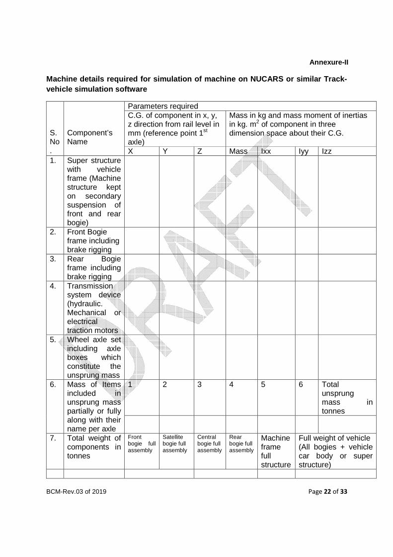
Annexure-II
Machine details required for simulation of machine on NUCARS or similar Track- vehicle simulation software
S.No.
Component’s Name
Parameters required C.G. of component in x, y, z direction from rail level in mm (reference point 1st
axle)
Mass in kg and mass moment of inertias in kg. m2 of component in three dimension space about their C.G.
X Y Z Mass Ixx Iyy Izz 1. Super structure
with vehicle frame (Machine structure kept on secondary suspension of front and rear bogie)
2. Front Bogie frame including brake rigging
3. Rear Bogie frame including brake rigging
4. Transmission system device (hydraulic. Mechanical or electrical traction motors
5. Wheel axle set including axle boxes which constitute the unsprung mass
6. Mass of Items included in unsprung mass partially or fully along with their name per axle
1 2 3 4 5 6 Total unsprung mass in tonnes
7. Total weight of components in tonnes
Front bogie full assembly
Satellite bogie full assembly
Central bogie full assembly
Rear bogie full assembly
Machine frame full structure
Full weight of vehicle (All bogies + vehicle car body or super structure)
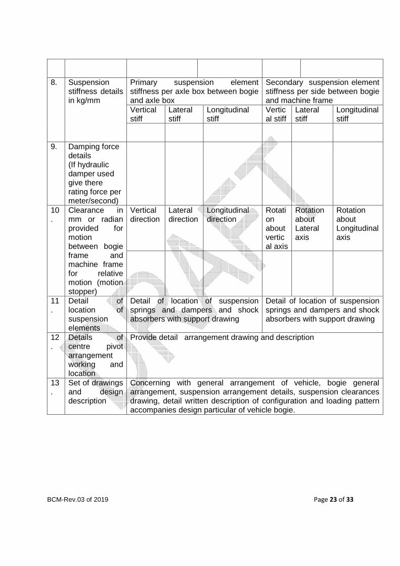
BCM-Rev.03 of 2019 Page 23 of 33
8. Suspension stiffness details in kg/mm
Primary suspension element stiffness per axle box between bogie and axle box
Secondary suspension element stiffness per side between bogie and machine frame
Vertical stiff
Lateral stiff
Longitudinal stiff
Vertical stiff
Lateral stiff
Longitudinal stiff
9. Damping force details (If hydraulic damper used give there rating force per meter/second)
10.
Clearance in mm or radian provided for motion between bogie frame and machine frame for relative motion (motion stopper)
Vertical direction
Lateral direction
Longitudinal direction
Rotation about vertical axis
Rotation about Lateral axis
Rotation about Longitudinal axis
11.
Detail of location of suspension elements
Detail of location of suspension springs and dampers and shock absorbers with support drawing
Detail of location of suspension springs and dampers and shock absorbers with support drawing
12.
Details of centre pivot arrangement working and location
Provide detail arrangement drawing and description
13.
Set of drawings and design description
Concerning with general arrangement of vehicle, bogie general arrangement, suspension arrangement details, suspension clearances drawing, detail written description of configuration and loading pattern accompanies design particular of vehicle bogie.

BCM-Rev.03 of 2019 Page 24 of 33
Annexure-III

BCM-Rev.03 of 2019 Page 25 of 33
Annexure-IV BALLAST PROFILE FOR LWR TRACK WITH OHE MAST ON TRAC K WITH PSC SLEEPERS
G Gauge
Type of Sleeper
A B C* D E* F F1 H Quantity of Ballast per meter in
Straight
Track (M3)
Curved
Track (M3)
1676
mm
PRC 250
300
350
350
350
350
500
500
500
2693
2772
2851
2851
2930
3009
7850
7850
7850
7850
7850
7850
646
698
751
2.030
2.304
2.585
2.120
2.401
2.690
Remarks :
1 Depth of ballast cushion should be provided as per Para 263(2)(a)of IRPWM.
2 Cross-Slope of 1 in 30 shall be provided for New Works.
3 Suitable dwarf walls shall be provided in case of cuttings, if necessary for retaining ballast.
4 *On outer side of curves only.
5 The cess width on existing track is to be increased on programmed basis wherever required so
that minimum cess width as per side slope given above is ensured.
6 All dimensions are in mm.
7 ** Marked Dimensions based on RDSO DRG. No.-TI/DRG./CIV/FND/RDSO/00001/04/0.
Taking into consideration, The distance of track center from the face of OHE mast as 2500
mm.
BCM-Rev.03 of 2019 Page 26 of 33
Annexure-V
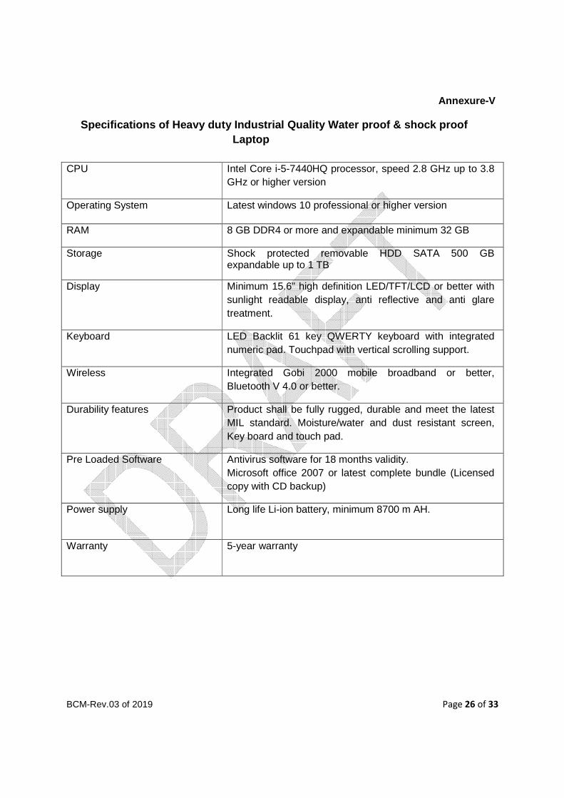
Specifications of Heavy duty Industrial Quality Wat er proof & shock proof Laptop
CPU Intel Core i-5-7440HQ processor, speed 2.8 GHz up to 3.8 GHz or higher version
Operating System Latest windows 10 professional or higher version
RAM 8 GB DDR4 or more and expandable minimum 32 GB
Storage Shock protected removable HDD SATA 500 GB expandable up to 1 TB
Display Minimum 15.6” high definition LED/TFT/LCD or better with sunlight readable display, anti reflective and anti glare treatment.
Keyboard LED Backlit 61 key QWERTY keyboard with integrated numeric pad. Touchpad with vertical scrolling support.
Wireless Integrated Gobi 2000 mobile broadband or better, Bluetooth V 4.0 or better.
Durability features Product shall be fully rugged, durable and meet the latest MIL standard. Moisture/water and dust resistant screen, Key board and touch pad.
Pre Loaded Software Antivirus software for 18 months validity. Microsoft office 2007 or latest complete bundle (Licensed copy with CD backup)
Power supply Long life Li-ion battery, minimum 8700 m AH.
Warranty 5-year warranty
BCM-Rev.03 of 2019 Page 27 of 33
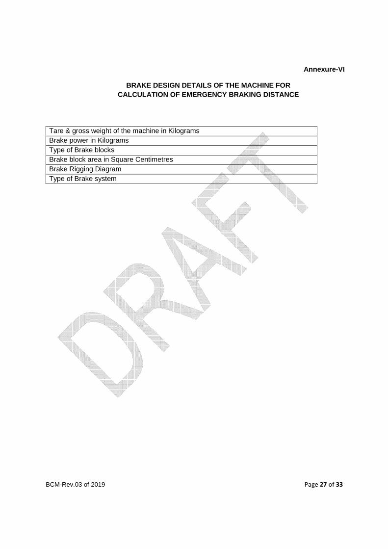
Annexure-VI
BRAKE DESIGN DETAILS OF THE MACHINE FOR CALCULATION OF EMERGENCY BRAKING DISTANCE
Tare & gross weight of the machine in Kilograms Brake power in Kilograms Type of Brake blocks Brake block area in Square Centimetres Brake Rigging Diagram Type of Brake system

BCM-Rev.03 of 2019 Page 28 of 33
Annexure-VII
INSPECTION CERTIFICATE
CERTIFICATE OF INSPECTION OF TRACK MACHINE (....... ....................................................) BY INSPECTING OFFICIAL AND APPROVAL FOR DESPATCH OF MACHINES. (STRIKE OUT WHICHEVER NOT APPLICABLE)
This is to certify that I have inspected the machine (type)_______________________________bearing Sr.No._________________ from (date) ____________to _____________at (Place) ________________ for its conformity/non-conformity with respect to the laid down Technical Specifications in contract Agreement No.________________________________ dated_______________________ between President of India through Director Track (Machines) and M/s. (Name of Supplier) ___________________________ ___________________________________.
The detailed Inspection Note regarding its conformity/non-conformity to the laid specifications is enclosed along with this certificate. It is observed that (strike out whichever is not applicable):-
• The Machine conforms to all the laid down specifications. • The machine conforms to all the laid down specifications except those at Sl.
No.________________________. • The above deviations are minor/major affecting/not affecting the performance of the
equipment in substantial way. The following T and P/manuals/drawings are to be supplied along with the machine:
1. __________________________ 2. __________________________ 3. __________________________
Based on the above, the Machine is certified/not certified to be conforming to the specifications.
The machine is approved/not approved for dispatch to _____________ ________________(Consignee) Indian Railways.
SIGNATURE AND DATE For M/s.__________________ INSPECTING OFFICIAL _________________________ (NAME AND DESIGNATION) for and on Behalf of President of India

BCM-Rev.03 of 2019 Page 29 of 33
Annexure-VIII
Particulars Required in Respect of the Rolling Stoc k under Consideration
1. A diagram showing elevation salient dimensions : a) Wheel spacing, Wheel diameter, bogie centres, and axle load. I. Overall length of the vehicle : II. Length over head stock : III. Length over buffers : IV. Distance apart for center of buffers : V. Max./Min. height of centers of buffers(above rail level) : b) I. Wheel base : II. Axle load (max) : III. Bogie Centres : 2. Wheel dimension : I. New : II. Worn out : 3. I. Tread and flange profile of the wheel indicating clearly
whether it is Indian Railways standard profile or differs from standard flange profile.
:
II. Wheel gauge dimension (back to back of tyre flange). : 4. Whether the stock is designed to be used as a general purpose or in a closed
circuit in specified sections under defined conditions. :
5. Maximum design speed : I. Own Power : II. In train formation 6. Unsprung weight per axle in tonnes I. Driving axle : II. Running axle : 7. Expected lateral force in tonnes per axle At maximum design speed. : 8. Increase in the impact load during motion(Dynamic Augment) : 9. Method of operation - Whether single only or coupling together is possible. If coupling is possible,
the number which can be coupled and what is trailing load. :
10. Maximum tractive effort at start and at the speed of operation - I. At working drive at start : at operation speed : II. At transfer drive at start :
BCM-Rev.03 of 2019 Page 30 of 33
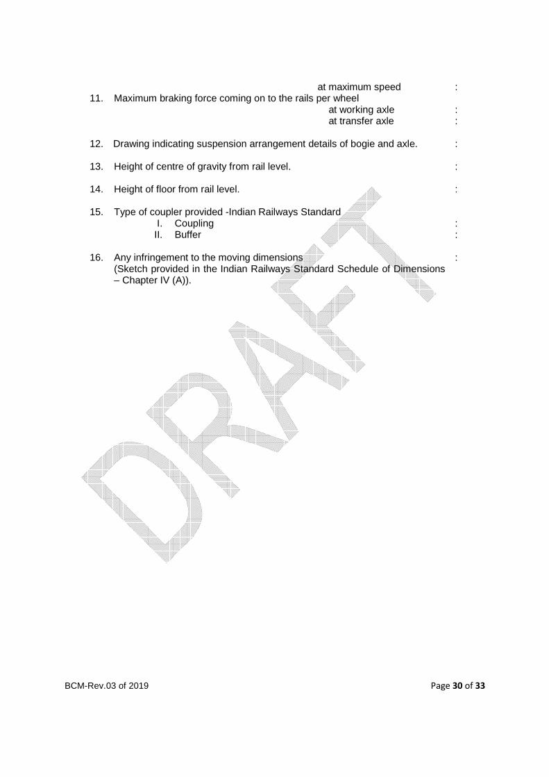
at maximum speed : 11. Maximum braking force coming on to the rails per wheel at working axle : at transfer axle : 12. Drawing indicating suspension arrangement details of bogie and axle. : 13. Height of centre of gravity from rail level. : 14. Height of floor from rail level. : 15. Type of coupler provided -Indian Railways Standard I. Coupling : II. Buffer : 16. Any infringement to the moving dimensions : (Sketch provided in the Indian Railways Standard Schedule of Dimensions
– Chapter IV (A)).
BCM-Rev.03 of 2019 Page 31 of 33
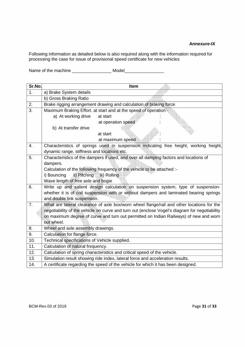
Annexure-IX
Following information as detailed below is also required along with the information required for processing the case for issue of provisional speed certificate for new vehicles
Name of the machine ________________ Model________________
Sr.No. Item 1. a) Brake System details b) Gross Braking Ratio 2. Brake rigging arrangement drawing and calculation of braking force 3. Maximum Braking Effort. at start and at the speed of operation -
a) At working drive at start : at operation speed :
b) At transfer drive at start :
at maximum speed : 4. Characteristics of springs used in suspension indicating free height, working height,
dynamic range, stiffness and locations etc. 5. Characteristics of the dampers if used, and over all damping factors and locations of
dampers. Calculation of the following frequency of the vehicle to be attached :- i) Bouncing ii) Pitching iii) Rolling Wave length of free axle and bogie
6. Write up and salient design calculation on suspension system, type of suspension- whether it is of coil suspension with or without dampers and laminated bearing springs and double link suspension.
7. What are lateral clearance of axle box/worn wheel flange/rail and other locations for the negotiability of the vehicle on curve and turn out (enclose Vogel’s diagram for negotiability on maximum degree of curve and turn out permitted on Indian Railways) of new and worn out wheel.
8. Wheel and axle assembly drawings. 9. Calculation for flange force. 10. Technical specifications of Vehicle supplied. 11. Calculation of natural frequency. 12. Calculation of spring characteristics and critical speed of the vehicle. 13. Simulation result showing ride index, lateral force and acceleration results. 14. A certificate regarding the speed of the vehicle for which it has been designed.
BCM-Rev.03 of 2019 Page 32 of 33
Annexure-X
ACCEPTANCE CRITERIA DURING OSCILLATION TRIALS
1. The speed potential of the machine offered by the firm should be established based upon oscillation trials conducted in India. The tests will be conducted at speed usually 10% higher than the maximum speed potential indicated by the firm for the machine under consideration and the following criteria satisfy for the same. For conducting the tests, a section of mainline track will be selected over which there is no temporary speed restrictions and which is considered by the Railway as being in a generally run down condition for mainline standards, but without speed restrictions. The vehicle will be tested generally for new and worn wheel clearance conditions and where relevant for operation in the forward and backward directions. The vehicle selected for tests will be one in average condition for normal maintenance.
2. The criteria applicable for establishing speed potential will be as follows:
a. A lateral force lasting over a length more than 2 metres should not exceed the Prud-Homme’s limit of K(1 + P/3) tonnes. Where P is the axle load in tonnes, K=0.85 for wooden sleepers and K= 1 for concrete sleepers.
b. Isolated peak values exceeding the above limit are permissible provided the record shows establishing characteristics of the vehicle subsequent to the disturbances.
c. A derailment coefficient should be worked out in the form of ratio between the lateral force (Hy) and the wheel load (Q) continuously over a period of 1/20th second, the value Hy/Q shall not exceed 1.
d. The values of acceleration recorded in the cab at location as near as possible to the bogie pivot (as near as possible to axle in case of four wheelers) shall be limited to 0.55 g both in vertical and lateral directions. The peak values up to 0.60 g may be permitted if the records do not indicate a resonant tendency in the region of peak value.
e. In the case of such vehicles where measurement of forces is not possible, the evaluation shall be in terms of ride index based on the accelerations measured as detailed in Para 2 (d) above which shall not be greater than 4.5 but a limit of 4.25 is preferred.
f. A general indication of stable running characteristics of the vehicle as evidenced by the movements of the bogie in straight and curved track and lateral force and derailment coefficient of accelerations as the case may be.

BCM-Rev.03 of 2019 Page 33 of 33
Annexure-XI
Details of rails and sleepers used for different Tr ack structures
Sr. No
Rails Sleepers
Rail Section
Weight (kg/m)
Height (mm)
Description Length (mm)
Width (bottom)
(mm)
Height (mm)
Weight (kg.) (approx.)
1. 60 kg 90 UTS
60.34 172 Wider Sleeper
2750 285 235 350
2. 52 kg 90 UTS
51.89 156 Concrete Sleeper
2750 250 210 300
3. 52 kg 72 UTS
51.89 156
4. 90 R 44.61 142.88