Embed Size (px)
Citation preview
PreliminaryMarch 2013, Revision BUnits 750-0501 to TBD
Specification &Description
S P E C I F I C AT I O N A N D D E S C R I P T I O N
U N I T S 7 5 0 - 0 5 0 1 T O T B D
M A R C H 2 0 1 3
R E V I S I O N B
P R E L I M I N A R Y
Citation Marketing
Cessna Aircraft Company
P.O. Box 7706
Wichita, Kansas 67277-7706Copyright 2012 Cessna Aircraft Company
1
March 2013, Revision B, Preliminary
I N T R O D U C T I O N
This document is published for the purpose of providinggeneral information for the evaluation of the design, per-formance, and equipment of the Cessna Citation X,Units 750-0501 to TBD. This document supersedes allprevious Specification and Description documents appli-cable to Units 750-0501 and On and describes only theCessna Citation X, Model 750, its powerplants andequipment.
Due to the time span between the date of thisSpecification and Description and the scheduled deliverydate of the Aircraft, Cessna reserves the right to revisethe Specification whenever occasioned by productimprovements, government regulations or other goodcause as long as such revisions do not result in a mate-rial reduction in performance.
In the event of any conflict or discrepancy between thisdocument and the terms and conditions of the PurchaseAgreement to which it is incorporated, the terms andconditions of the Purchase Agreement govern.
For additional information contact:
Citation MarketingCessna Aircraft CompanyP.O. Box 7706Wichita, Kansas 67277-7706
Telephone: 316-517-6449Telefax: 316-517-6640
WARNING: This product contains Halon 1211 and Halon 1301. Furthermore, the product was manufacturedwith 1-1-1 Trichloroethane, substances which harm public health and environment by destroying ozone in theupper atmosphere.
2
March 2013, Revision B, Preliminary
TA B L E O F C O N T E N T SCessna Citation X Specification and Description
Section Page
1. General Description . . . . . . . . . . . . . . . . . . . . . . . . . . . . . . . . . . . . . . . . . . . . . . . . . . . . . . . . . . . . . . . . . . . . 31.1 Certification . . . . . . . . . . . . . . . . . . . . . . . . . . . . . . . . . . . . . . . . . . . . . . . . . . . . . . . . . . . . . . . . . . . . . . 31.2 Approximate Dimensions . . . . . . . . . . . . . . . . . . . . . . . . . . . . . . . . . . . . . . . . . . . . . . . . . . . . . . . . . . . 31.3 Design Weight and Capacities . . . . . . . . . . . . . . . . . . . . . . . . . . . . . . . . . . . . . . . . . . . . . . . . . . . . . . . 6
2. Performance . . . . . . . . . . . . . . . . . . . . . . . . . . . . . . . . . . . . . . . . . . . . . . . . . . . . . . . . . . . . . . . . . . . . . . . . . . 63. Structural Design Criteria . . . . . . . . . . . . . . . . . . . . . . . . . . . . . . . . . . . . . . . . . . . . . . . . . . . . . . . . . . . . . . . . 74. Fuselage . . . . . . . . . . . . . . . . . . . . . . . . . . . . . . . . . . . . . . . . . . . . . . . . . . . . . . . . . . . . . . . . . . . . . . . . . . . . 75. Wing . . . . . . . . . . . . . . . . . . . . . . . . . . . . . . . . . . . . . . . . . . . . . . . . . . . . . . . . . . . . . . . . . . . . . . . . . . . . . . . 76. Empennage . . . . . . . . . . . . . . . . . . . . . . . . . . . . . . . . . . . . . . . . . . . . . . . . . . . . . . . . . . . . . . . . . . . . . . . . . . 87. Landing Gear . . . . . . . . . . . . . . . . . . . . . . . . . . . . . . . . . . . . . . . . . . . . . . . . . . . . . . . . . . . . . . . . . . . . . . . . . 88. Powerplants . . . . . . . . . . . . . . . . . . . . . . . . . . . . . . . . . . . . . . . . . . . . . . . . . . . . . . . . . . . . . . . . . . . . . . . . . . 89. Systems . . . . . . . . . . . . . . . . . . . . . . . . . . . . . . . . . . . . . . . . . . . . . . . . . . . . . . . . . . . . . . . . . . . . . . . . . . . . . 9
9.1 Flight Controls . . . . . . . . . . . . . . . . . . . . . . . . . . . . . . . . . . . . . . . . . . . . . . . . . . . . . . . . . . . . . . . . . . . . 99.2 Fuel System . . . . . . . . . . . . . . . . . . . . . . . . . . . . . . . . . . . . . . . . . . . . . . . . . . . . . . . . . . . . . . . . . . . . . 99.3 Hydraulic System . . . . . . . . . . . . . . . . . . . . . . . . . . . . . . . . . . . . . . . . . . . . . . . . . . . . . . . . . . . . . . . . . 99.4 Electrical System . . . . . . . . . . . . . . . . . . . . . . . . . . . . . . . . . . . . . . . . . . . . . . . . . . . . . . . . . . . . . . . . . . 99.5 Autothrottle System . . . . . . . . . . . . . . . . . . . . . . . . . . . . . . . . . . . . . . . . . . . . . . . . . . . . . . . . . . . . . . . . 99.6 Pressurization and Environmental System . . . . . . . . . . . . . . . . . . . . . . . . . . . . . . . . . . . . . . . . . . . . . . 99.7 Oxygen System . . . . . . . . . . . . . . . . . . . . . . . . . . . . . . . . . . . . . . . . . . . . . . . . . . . . . . . . . . . . . . . . . . . 99.8 Ice Protection . . . . . . . . . . . . . . . . . . . . . . . . . . . . . . . . . . . . . . . . . . . . . . . . . . . . . . . . . . . . . . . . . . . . 9
10. Flight Compartment, Instrumentation and Avionics . . . . . . . . . . . . . . . . . . . . . . . . . . . . . . . . . . . . . . . . . . . . 1010.1 General . . . . . . . . . . . . . . . . . . . . . . . . . . . . . . . . . . . . . . . . . . . . . . . . . . . . . . . . . . . . . . . . . . . . . . . . . 1010.2 Instrument and Control Panels . . . . . . . . . . . . . . . . . . . . . . . . . . . . . . . . . . . . . . . . . . . . . . . . . . . . . . . 1010.3 Avionics . . . . . . . . . . . . . . . . . . . . . . . . . . . . . . . . . . . . . . . . . . . . . . . . . . . . . . . . . . . . . . . . . . . . . . . . . 12
11. Interior . . . . . . . . . . . . . . . . . . . . . . . . . . . . . . . . . . . . . . . . . . . . . . . . . . . . . . . . . . . . . . . . . . . . . . . . . . . . . . . 1411.1 General . . . . . . . . . . . . . . . . . . . . . . . . . . . . . . . . . . . . . . . . . . . . . . . . . . . . . . . . . . . . . . . . . . . . . . . . . 1411.2 Cabin . . . . . . . . . . . . . . . . . . . . . . . . . . . . . . . . . . . . . . . . . . . . . . . . . . . . . . . . . . . . . . . . . . . . . . . . . . . 1511.3 Baggage Compartment . . . . . . . . . . . . . . . . . . . . . . . . . . . . . . . . . . . . . . . . . . . . . . . . . . . . . . . . . . . . . 15
12. Exterior . . . . . . . . . . . . . . . . . . . . . . . . . . . . . . . . . . . . . . . . . . . . . . . . . . . . . . . . . . . . . . . . . . . . . . . . . . . . . . 1613. Additional Equipment . . . . . . . . . . . . . . . . . . . . . . . . . . . . . . . . . . . . . . . . . . . . . . . . . . . . . . . . . . . . . . . . . . . 1614. Emergency Equipment . . . . . . . . . . . . . . . . . . . . . . . . . . . . . . . . . . . . . . . . . . . . . . . . . . . . . . . . . . . . . . . . . . 1615. Documentation and Technical Publications . . . . . . . . . . . . . . . . . . . . . . . . . . . . . . . . . . . . . . . . . . . . . . . . . . 1616. Computerized Maintenance Record Service . . . . . . . . . . . . . . . . . . . . . . . . . . . . . . . . . . . . . . . . . . . . . . . . . 1717. Limited Warranties . . . . . . . . . . . . . . . . . . . . . . . . . . . . . . . . . . . . . . . . . . . . . . . . . . . . . . . . . . . . . . . . . . . . . 17
17.1 Cessna Citation X Limited Warranty . . . . . . . . . . . . . . . . . . . . . . . . . . . . . . . . . . . . . . . . . . . . . . . . . . . 1717.2 Rolls-Royce Engine Warranty . . . . . . . . . . . . . . . . . . . . . . . . . . . . . . . . . . . . . . . . . . . . . . . . . . . . . . . . 1817.3 Summary of Honeywell APU Warranty . . . . . . . . . . . . . . . . . . . . . . . . . . . . . . . . . . . . . . . . . . . . . . . . . 20
18. Citation X Crew Training Agreement . . . . . . . . . . . . . . . . . . . . . . . . . . . . . . . . . . . . . . . . . . . . . . . . . . . . . . . 21FIGURE I — CITATION X EXTERIOR DIMENSIONS . . . . . . . . . . . . . . . . . . . . . . . . . . . . . . . . . . . . . . . . . . . . . 4FIGURE II — CITATION X INTERIOR DIMENSIONS . . . . . . . . . . . . . . . . . . . . . . . . . . . . . . . . . . . . . . . . . . . . . . 5FIGURE III — CITATION X INSTRUMENT PANEL AND PEDESTAL LAYOUT . . . . . . . . . . . . . . . . . . . . . . . . . . . 11FIGURE IV — CITATION X STANDARD INTERIOR ARRANGEMENT . . . . . . . . . . . . . . . . . . . . . . . . . . . . . . . . . 14

3
March 2013, Revision B, Preliminary
M A N U FA C T U R E R C E S S N A A I R C R A F T C O M PA N Y
M O D E L 7 5 0
1 . G E N E R A L D E S C R I P T I O N
The Cessna Citation X is a transcontinental swept-wingbusiness jet utilizing new generation Rolls-RoyceAE3007C2 turbofan powerplants with a fully integratedGarmin G5000 digital avionics suite. A pressurized cabinaccommodates a crew of two plus eight to twelve pas-sengers (nine is standard).
Cessna provides a third-party training package for pilotsand mechanics as well as a comprehensive warranty asdescribed in this book. Cessna's worldwide network ofservice centers offers a complete source for all servicingneeds.1.1 Certification
Certification is to the requirements of U.S. 14 CFR, Part25 transport category, including day, night, VFR, IFR,
and flight-into-known icing conditions. WAAS LPVapproach capability as well as Category II capability perPart 91 are also included. The Citation X also meets therequirements for operation within RVSM airspace. (Note:specific approval is required for operation within RVSMairspace; Cessna offers a no-charge service to assistwith this process.)
The purchaser is responsible for obtaining aircraft oper-ating approval from the relevant civil aviation authority.International certification may require modifications andadditional equipment; such costs are the responsibility ofthe Purchaser.
1.2 Approximate Dimensions
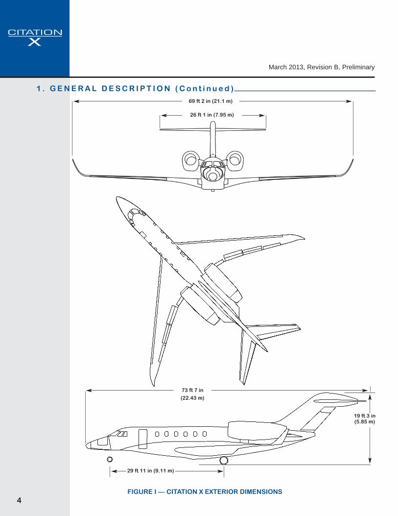
Overall Height . . . . . . . . . . . . . . . . . . . . . . . . . . . . . . . . . . . . . . . . . . . . . . . . . . . . . . . . . . . . . . . . . . . 19 ft 3 in (5.85 m)Overall Width . . . . . . . . . . . . . . . . . . . . . . . . . . . . . . . . . . . . . . . . . . . . . . . . . . . . . . . . . . . . . . . . . . . 69 ft 2 in (21.1 m)Overall Length . . . . . . . . . . . . . . . . . . . . . . . . . . . . . . . . . . . . . . . . . . . . . . . . . . . . . . . . . . . . . . . . . 73 ft 7 in (22.43 m)
Wing
Span (overall) . . . . . . . . . . . . . . . . . . . . . . . . . . . . . . . . . . . . . . . . . . . . . . . . . . . . . . . . . . . . . . . . . 69 ft 2 in (21.1 m)Area . . . . . . . . . . . . . . . . . . . . . . . . . . . . . . . . . . . . . . . . . . . . . . . . . . . . . . . . . . . . . . . . . . . . . . . . . . 527 ft2 (48.9 m2)Sweepback (at outboard 25% chord) . . . . . . . . . . . . . . . . . . . . . . . . . . . . . . . . . . . . . . . . . . . . . . . . . . . . 37 degrees
Horizontal Tail
Span (overall) . . . . . . . . . . . . . . . . . . . . . . . . . . . . . . . . . . . . . . . . . . . . . . . . . . . . . . . . . . . . . . . . . 26 ft 1 in (7.95 m)Area . . . . . . . . . . . . . . . . . . . . . . . . . . . . . . . . . . . . . . . . . . . . . . . . . . . . . . . . . . . . . . . . . . . . . . . . . . 120 ft2 (11.1 m2)Sweepback (at 25% chord) . . . . . . . . . . . . . . . . . . . . . . . . . . . . . . . . . . . . . . . . . . . . . . . . . . . . . . . . . . . . 40 degrees
Vertical Tail
Span . . . . . . . . . . . . . . . . . . . . . . . . . . . . . . . . . . . . . . . . . . . . . . . . . . . . . . . . . . . . . . . . . . . . . . . . 10 ft 7 in (3.23 m)Area . . . . . . . . . . . . . . . . . . . . . . . . . . . . . . . . . . . . . . . . . . . . . . . . . . . . . . . . . . . . . . . . . . . . . . . . . . 111 ft2 (10.3 m2)Sweepback (at 25% chord) . . . . . . . . . . . . . . . . . . . . . . . . . . . . . . . . . . . . . . . . . . . . . . . . . . . . . . . . . . . 52 degrees
Cabin
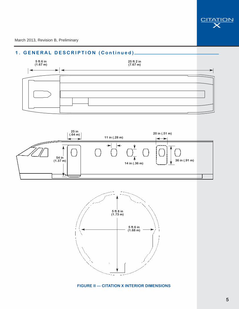
Height (maximum over aisle) . . . . . . . . . . . . . . . . . . . . . . . . . . . . . . . . . . . . . . . . . . . . . . . . . . . . . . 5 ft 8 in (1.73 m)Width (max) . . . . . . . . . . . . . . . . . . . . . . . . . . . . . . . . . . . . . . . . . . . . . . . . . . . . . . . . . . . . . . . . . . . . 5 ft 6 in (1.68 m)Length (forward pressure bulkhead to mid pressure bulkhead) . . . . . . . . . . . . . . . . . . . . . . . . . . . 30 ft 8 in (9.32 m)
Landing Gear
Tread (main to main) . . . . . . . . . . . . . . . . . . . . . . . . . . . . . . . . . . . . . . . . . . . . . . . . . . . . . . . . . . . 10 ft 7 in (3.23 m)Wheelbase (nose to main) . . . . . . . . . . . . . . . . . . . . . . . . . . . . . . . . . . . . . . . . . . . . . . . . . . . . . . 29 ft 11 in (9.11 m)
4
March 2013, Revision B, Preliminary
FIGURE I — CITATION X EXTERIOR DIMENSIONS
26 ft 1 in (7.95 m)
19 ft 3 in(5.85 m)
29 ft 11 in (9.11 m)
69 ft 2 in (21.1 m)
73 ft 7 in
(22.43 m)
1 . G E N E R A L D E S C R I P T I O N ( C o n t i n u e d )
5
March 2013, Revision B, Preliminary
FIGURE II — CITATION X INTERIOR DIMENSIONS
5 ft 6 in (1.67 m)
5 ft 8 in(1.73 m)
5 ft 6 in(1.68 m)
36 in (.91 m)
20 in (.51 m)11 in (.28 m)
14 in (.36 m)
54 in(1.37 m)
25 in(.64 m)
25 ft 2 in(7.67 m)
1 . G E N E R A L D E S C R I P T I O N ( C o n t i n u e d )
6
March 2013, Revision B, Preliminary
2 . P E R F O R M A N C E
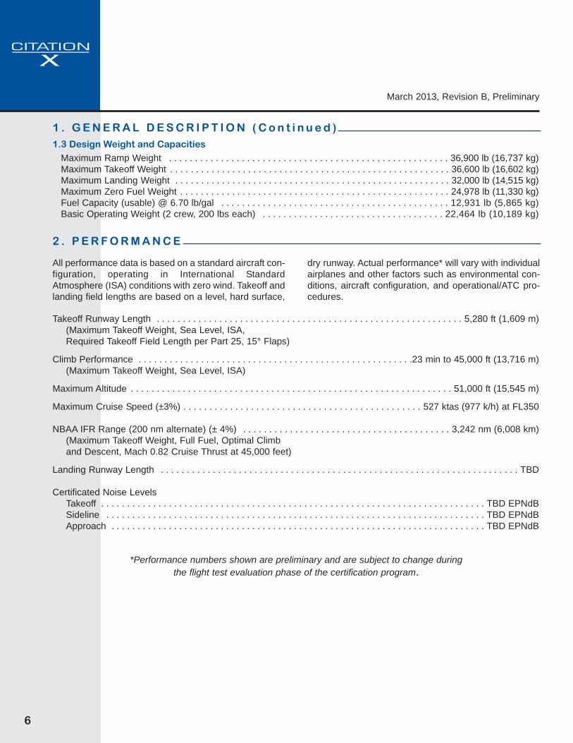
1 . G E N E R A L D E S C R I P T I O N ( C o n t i n u e d )1.3 Design Weight and Capacities
Maximum Ramp Weight . . . . . . . . . . . . . . . . . . . . . . . . . . . . . . . . . . . . . . . . . . . . . . . . . . . . . . 36,900 lb (16,737 kg)Maximum Takeoff Weight . . . . . . . . . . . . . . . . . . . . . . . . . . . . . . . . . . . . . . . . . . . . . . . . . . . . . . 36,600 lb (16,602 kg)Maximum Landing Weight . . . . . . . . . . . . . . . . . . . . . . . . . . . . . . . . . . . . . . . . . . . . . . . . . . . . . 32,000 lb (14,515 kg)Maximum Zero Fuel Weight . . . . . . . . . . . . . . . . . . . . . . . . . . . . . . . . . . . . . . . . . . . . . . . . . . . . 24,978 lb (11,330 kg)Fuel Capacity (usable) @ 6.70 lb/gal . . . . . . . . . . . . . . . . . . . . . . . . . . . . . . . . . . . . . . . . . . . . 12,931 lb (5,865 kg)Basic Operating Weight (2 crew, 200 lbs each) . . . . . . . . . . . . . . . . . . . . . . . . . . . . . . . . . . . 22,464 lb (10,189 kg)
Takeoff Runway Length . . . . . . . . . . . . . . . . . . . . . . . . . . . . . . . . . . . . . . . . . . . . . . . . . . . . . . . . . . . 5,280 ft (1,609 m)(Maximum Takeoff Weight, Sea Level, ISA,Required Takeoff Field Length per Part 25, 15° Flaps)
Climb Performance . . . . . . . . . . . . . . . . . . . . . . . . . . . . . . . . . . . . . . . . . . . . . . . . . . . . .23 min to 45,000 ft (13,716 m)(Maximum Takeoff Weight, Sea Level, ISA)
Maximum Altitude . . . . . . . . . . . . . . . . . . . . . . . . . . . . . . . . . . . . . . . . . . . . . . . . . . . . . . . . . . . . . . 51,000 ft (15,545 m)
Maximum Cruise Speed (±3%) . . . . . . . . . . . . . . . . . . . . . . . . . . . . . . . . . . . . . . . . . . . . . . 527 ktas (977 k/h) at FL350
NBAA IFR Range (200 nm alternate) (± 4%) . . . . . . . . . . . . . . . . . . . . . . . . . . . . . . . . . . . . . . . . 3,242 nm (6,008 km)(Maximum Takeoff Weight, Full Fuel, Optimal Climband Descent, Mach 0.82 Cruise Thrust at 45,000 feet)
Landing Runway Length . . . . . . . . . . . . . . . . . . . . . . . . . . . . . . . . . . . . . . . . . . . . . . . . . . . . . . . . . . . . . . . . . . . . . TBD
Certificated Noise LevelsTakeoff . . . . . . . . . . . . . . . . . . . . . . . . . . . . . . . . . . . . . . . . . . . . . . . . . . . . . . . . . . . . . . . . . . . . . . . . . . TBD EPNdBSideline . . . . . . . . . . . . . . . . . . . . . . . . . . . . . . . . . . . . . . . . . . . . . . . . . . . . . . . . . . . . . . . . . . . . . . . . . TBD EPNdBApproach . . . . . . . . . . . . . . . . . . . . . . . . . . . . . . . . . . . . . . . . . . . . . . . . . . . . . . . . . . . . . . . . . . . . . . . . TBD EPNdB
*Performance numbers shown are preliminary and are subject to change during the flight test evaluation phase of the certification program.
All performance data is based on a standard aircraft con-figuration, operating in International StandardAtmosphere (ISA) conditions with zero wind. Takeoff andlanding field lengths are based on a level, hard surface,
dry runway. Actual performance* will vary with individualairplanes and other factors such as environmental con-ditions, aircraft configuration, and operational/ATC pro-cedures.

7
March 2013, Revision B, Preliminary
4 . F U S E L A G EA circular fuselage section is utilized with an internalcabin width of 5 ft 6 in (1.68 m). A continuous droppedaisle in the passenger cabin provides approximately 5 ft8 in (1.73 m) of standup headroom measured softgoodsto softgoods, with a cabin length (excluding cockpit) of25 ft 2 in (7.67 m): an additional 15 inches of length com-pared to aircraft prior to Unit 750-0501.
The nose section incorporates a contoured radome. Thewindshields are designed to meet bird resistancerequirements of Part 25, and are all-glass design andelectrically heated and defogged.
The aft fuselage incorporates a 72.0 cubic feet (2.04 m3)heated and pressurized baggage compartment. A doorin the left hand side of the fuselage provides access. Anadditional 10.0 cubic feet (.28 m3) utility cargo area isaccessed through the lower tailcone door. This cargoarea is 83.0 inches (2.11 m) long and provides storagefor cargo such as skis. Area rule design is utilized for theaft fuselage area, consistent with low-drag characteris-tics. The aft fuselage also incorporates servicing portsfor the hydraulic system and for external toilet servicing.
5 . W I N G
A highly swept wing utilizing super critical airfoil technol-ogy tailored to the Model 750 is incorporated. Speedbrakes and spoiler design are optimized for drag controlwith minimum pitching moments.
Dual hydraulically-powered non-reversible controls areincorporated.
The wing incorporates fuselage attachment points and adropped carry-through which permits a continuousdropped aisle throughout the passenger cabin and lava-tory.
A large aerodynamic fairing is optimized for low drag.
3 . S T R U C T U R A L D E S I G N C R I T E R I A
Limit SpeedsVMO at Sea Level to 8,000 ft (2,438 m) . . . . . . . . . . . . . . . . . . . . . . . . . . . . . . . . . 270 KIAS (500 km/hr, 311 mph)VMO at 8,000 ft (2,438 m) to 30,650 ft (9,342 m) . . . . . . . . . . . . . . . . . . . . . . . . . . 350 KIAS (649 km/hr, 403 mph)MMO at 30,650 ft (9,342 m) to 51,000 ft (15,545 m) . . . . . . . . . . . . . . . . . . . . . . . . . . . . . . . . . . . . . . . Mach 0.935
Flap Extension SpeedsVFE at Takeoff and Approach (5° flaps) . . . . . . . . . . . . . . . . . . . . . . . . . . . . . . . . . 250 KIAS (463 km/hr, 288 mph)VFE (15° flaps) . . . . . . . . . . . . . . . . . . . . . . . . . . . . . . . . . . . . . . . . . . . . . . . . . . . . 210 KIAS (389 km/hr, 242 mph)VFE at Landing Extension (full flaps) . . . . . . . . . . . . . . . . . . . . . . . . . . . . . . . . . . . .180 KIAS (333 km/hr, 207 mph)
Landing Gear Operating and Extended SpeedVLO . . . . . . . . . . . . . . . . . . . . . . . . . . . . . . . . . . . . . . . . . . . . . . . . . . . . . . . . . . . . . 210 KIAS (389 km/hr, 242 mph)VLE . . . . . . . . . . . . . . . . . . . . . . . . . . . . . . . . . . . . . . . . . . . . . . . . . . . . . . . . . . . . . 210 KIAS (389 km/hr, 242 mph)
8
March 2013, Revision B, Preliminary
7 . L A N D I N G G E A R
The main landing gear is a trailing link design utilizingdual wheels, tires and powered anti-skid carbon brakes.
The nose gear is a conventional strut design with dualwheels and tires. Nose gear steering is provided by ahydraulic power steering system.
8 . P O W E R P L A N T SThe aircraft is powered by two modular design Rolls-Royce AE3007C2 turbofan engines installed on the rearfuselage.
The AE3007C2 engines incorporate dual channel FullAuthority Digital Electronic Controls (FADEC) which arefully compatible with the Autothrottle (A/T) system. Theengine is a modular design and features six large accesspanels for Line Replacement Unit (LRU) maintenanceand multiple borescope inspection ports.
An APU is incorporated for engine start and other bene-fits, and is certified for in-flight use up to 31,000 feet. TheAPU is located in the tailcone stinger for ease of main-tenance.
Hydraulically actuated, target-type thrust reversers com-patible with the engine nacelles and powerplants areincluded.
The empennage incorporates a highly swept T-tail with amoveable horizontal stabilizer for trim. Elevators and thelower portion of a two-piece rudder are hydraulicallypowered.
The upper portion of the rudder is electrically powered.An elevator control column shaker barrier is installed.
6 . E M P E N N A G E
9
March 2013, Revision B, Preliminary
9.1 Flight Controls
The primary flight controls are hydraulically poweredwith a dual, isolated hydraulic system and manual back-up. All control surfaces, spoilers, speedbrakes and flapsare of composite construction. Dual independant yawdamper systems are incorporated. There are three flappanels per side which are electrically operated by a DCsystem.
9.2 Fuel System
Three separate fuel tanks are incorporated, two wingtanks and one center tank (in both wing and forward fair-ing). The fuel supply systems are two independent sys-tems located in the wing tanks. The center tank transfersfuel to the wing tanks. The total usable fuel is 12,931pounds (5,865 kg). Both single point and over wing refu-eling are provided.
9.3 Hydraulic System
A dual isolated hydraulic system utilizes pressure com-pensated pumps which maintain a continuous pressureof approximately 3,000 psi (206.8 bar).
9.4 Electrical System
The electrical system is a split-bus system powered bytwo engine-driven, 400 amp, brushless DC generators.In addition, a third generator is driven by the APU whenthe APU is operating. Two 44-amp hour Nickel-Cadmiumbatteries are provided.
Each engine also drives an alternator in support of analternating current (AC) system for electrical anti-icingand defogging of the glass windshields. In the unlikelyevent of a dual generator loss, the alternators can alsoprovide backup electrical power through transformer-rectifier units to an essential electrical bus. The essentialbus can power components of the G5000 system thatare essential for flight, including two display units andthe flight director functionality. This essential bus designand its multiple power sources provide much higher reli-ability and a greater situational awareness in the eventof an electrical emergency. If all engine-driven powersources are lost, the aircraft main batteries providepower to the emergency bus for a limited period of time.
Interconnect wiring for the electrical components isdesigned to minimize susceptibility of critical and essen-tial systems to High Intensity Radiated Fields (HIRF).
Cabin electrical grounds have been organized to cen-tralize and simplify access.
Standard exterior lighting consists of two pulsing redLED lights for ground recognition, LED anti-collisionlights and two downwash lights located in the winglets,two wing inspection lights, LED position lights, two land-ing/recognition lights (including the Precise Flightpulselite system which, when activated, pulses the land-ing/recognition lights), windshield ice detection lightsand taxi lights (located on the nose landing gear). TwoLED tail logo lights are located on the aft end of theengine pylon illuminating the vertical stabilizer surfaces.
9.5 Autothrottle System
The autothrottle (A/T) is fully integrated with theAutomatic Flight Control System (AFCS) and the FlightManagement Systems (FMS) to control the enginethrust throughout the flight from takeoff to landing. TheA/T includes speed as well as thrust modes and may beselected prior to initiating takeoff roll and remainengaged throughout the flight, approach, flare and land-ing touchdown (Aircraft does not incorporate autolandcapability). The A/T may be disengaged for manual throt-tle control.
9.6 Pressurization and Environmental System
Cabin pressurization is supplied by bleed air from eachengine. The system has a 9.3 psi (.64 bar) nominal max-imum pressure differential and provides an 8,000 foot(2,438 m) cabin altitude at 51,000 feet (15,540 m). Cabinpressure and cabin rate of climb are displayed on themultifunction display (MFD).
9.7 Oxygen System
A 76.0 cubic foot (2.15 m3) oxygen bottle and a 49 cubicfoot (1.38 m3) oxygen bottle are provided. Oxygen pres-sure readout is available on the MFD. An automaticdropout oxygen mask is provided for each passenger.Pressure demand masks are provided for the crew.
9.8 Ice Protection
The wing leading edge, horizontal stabilizer leadingedge and engine inlets are heated by bleed air. Electricheat is used for the windshield, wing cuff, pitot/static sys-tem, AOA systems and RAT probe.
9 . S Y S T E M S
10
March 2013, Revision B, Preliminary
1 0 . F L I G H T C O M PA R T M E N T, I N S T R U M E N TAT I O N A N D A V I O N I C S10.1 General
The Garmin G5000 system is the featured avionics suiteon the Citation X. It includes an integrated Flight Director/Autopilot and Electronic Flight Instrument System (EFIS)utilizing three fourteen-inch (diagonal) high-resolutionLiquid Crystal Displays (LCD) in widescreen, landscapeorientation. The two outer displays are Primary FlightDisplays (PFDs) and the centrally located MultifunctionDisplay (MFD) incorporates engine and systems informa-tion as well as detailed charts, moving map, synoptics, traf-fic, and TAWS functionality.
Four full-color, touchscreen control panels provide thecrew with the ability to control G5000 system featuressuch as radio tuning, transponders, intercom, flight plan-ning and display information as desired. The controlpanels also provide control of selected aircraft systemssuch as environmental control and external lighting. Theoutboard touchscreen controllers are primarily utilizedfor PFD control while the inboard two touchscreen con-trollers are primarily used for MFD control. In the unlike-ly event a touchscreen controller becomes inoperative,the remaining controllers can take on additional controlresponsibility.
Two complete crew stations are provided with dual con-trols including control columns, adjustable rudder ped-als, and brakes. The crew seats are fully adjustable andinclude five-point restraint harnesses.
LED illuminated panels, instrument floodlights, and blue-white background lighting are provided for all cockpitinstruments and switches. Illuminated LED pushbuttonswitches, overhead map lights and floodlights are alsoprovided. The emergency oxygen system provides twopressure demand masks with microphones for the crewmembers. Circuit breakers are installed on circuit break-er panels located on the pilot's and copilot's sidewalls.
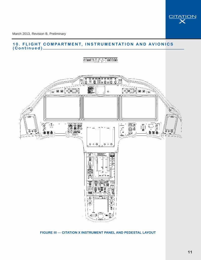
10.2 Instrument and Control Panels
The instrument layout includes a tilt panel below the ver-tical instrument panel across the width of the cockpit.The tilt panel improves visibility of components mountedlow in the panel. Oxygen mask stowage has been incor-porated in the lower sidewall.
A. Installed on Left-Hand Panel (pilot):
• Touchscreen LCD Control Panel• Primary Flight Display (PFD)• Secondary PFD Controller
B. Installed on Right-Hand Panel (copilot):
• Touchscreen LCD Control Panel• Primary Flight Display (PFD)• Secondary PFD Controller
C. Installed on Center Panel:
• Multifunction Display (MFD)• Dual Touchscreen LCD Control Panels• Electronic Standby Flight Display - ESFD
D. Installed Beneath Glareshield:
• Flight Guidance Panel - FGP
E. Installed on LH Tilt Panel:
• Electrical Power Panel
F. Installed on RH Tilt Panel:
• Anti-Ice/De-Ice Panel• Landing Gear Control Panel
G. Installed on Pedestal:
• Engine power levers - Autothrottle assembly• Flaps/Slats control• Speed Brake Control Lever• Pressurization Panel• Engine Control/Start Panel
11
March 2013, Revision B, Preliminary
FIGURE III — CITATION X INSTRUMENT PANEL AND PEDESTAL LAYOUT
1 0 . F L I G H T C O M PA R T M E N T, I N S T R U M E N TAT I O N A N D A V I O N I C S( C o n t i n u e d )

12
March 2013, Revision B, Preliminary
1 0 . F L I G H T C O M PA R T M E N T, I N S T R U M E N TAT I O N A N D A V I O N I C S( C o n t i n u e d )
10.3 Avionics
Described below is the Citation X standard avionicssuite as referred to in section 17, Limited Warranties.
A. Flight Displays
The Garmin G5000 avionics system in the Citation Xfeatures three fourteen-inch (diagonal), widescreen-for-mat liquid crystal displays (LCDs). Two Primary FlightDisplays (PFDs) are located on the pilot's and copilot'sinstrument panels, and one Multi-Function Display(MFD) is located on the center panel. In addition to flightdisplay information, the PFDs can display an inset win-dow with moving map imagery. Color-coded CrewAlerting System (CAS) messages are displayed on thePFD. The MFD displays detailed moving map, terrain,traffic, and weather information as well as a dedicatedengine and systems information window. Display ofelectronic charts and taxi diagrams with aircraft positionshown is included. (Applicable subscription services arethe responsibility of the Purchaser.) In addition, aircraftsystem synoptic diagrams are available for display onthe MFD. The PFDs and the MFD can operate in full-screen or split-screen mode. Multiple reversionary dis-play formats provide for redundancy.
B. Synthetic Vision Technology
Garmin Synthetic Vision Technology (SVT) is included.The system presents terrain and obstacle information onthe PFDs in a dynamic, three-dimensional format, pro-viding for increased situational awareness. Airports, run-ways, heading, traffic, color-coded terrain alerts, and aflight path indicator are displayed on the SVT presenta-tion.
C. Touchscreen Control Panels
Four full-color, touchscreen LCD control panels providethe primary user interface with the G5000 system. Twocontrol panels are located on the center pedestal, andtwo additional panels occupy positions outboard of eachPFD. The control panels provide pilots with the ability toarrange and tailor display information, tune communica-tion and navigation radios, and manage specific aircraftsystems. Multiple reversionary modes provide for con-trol redundancy.
D. Automatic Flight Control System
The G5000 system includes a full-featured AutomaticFlight Control System (AFCS) that supports dual flightdirectors and a three-axis autopilot. Multiple computa-tional paths in the system provide for a high level of
redundancy. The AFCS also provides yaw damping aswell as mach trim functionality. Pilot control is providedthrough a single AFCS mode controller centrally locatedin the glareshield. The AFCS integrates with theautothrottle system and includes an EmergencyDescent Mode that provides automatic aircraft descentto 15,000 feet should the aircraft cabin experiencedepressurization at high altitude.
E. Inertial Navigation System (INS)
Dual Inertial Navigation Systems (INS) provide attitudeand heading reference as well as inertial navigationinformation, including the capability to support RequiredNavigation Performance (RNP) operations.
F. Integrated Avionics Units
Dual Integrated Avionics Units include GlobalPositioning System (GPS) Wide Area AugmentationSystem (WAAS) receivers, Very High Frequency (VHF)communication radios, VHF navigation radios, andglideslope receivers in addition to supporting input/out-put processing, aural alert generation, and flight directorfunctions.
G. Distance Measuring Equipment
Dual scanning Distance Measuring Equipment (DME)units are installed to provide DME information to thepilots as well as to provide scanning DME/DME inputcapability for the Flight Management Systems.
H. Flight Management Systems
Dual Flight Management Systems (FMS) provide exten-sive navigation and flight planning capabilities as well asenroute, takeoff, and landing performance calculations.Supported navigation capabilities include the following(among others):
•Enroute and terminal operations•Precision and non-precision approach operations,including LNAV/VNAV and Localizer Performance withVertical Guidance (LPV) approaches•Required Navigation Performance (RNP) 0.3approaches with radius-to-fix (RF) legs, including thoserequiring Approval Required (AR) capability and havinga missed approach segment RNP value less than 1nautical mile.
The FMSs calculate aircraft position based uponGPS/WAAS, INS, as well as scanning DME/DME input.(Applicable FMS database subscription services are theresponsibility of the Purchaser.)
13
March 2013, Revision B, Preliminary
1 0 . F L I G H T C O M PA R T M E N T, I N S T R U M E N TAT I O N A N D A V I O N I C S( C o n t i n u e d )
I. Weather Radar
A Garmin GWX 70 weather radar system with a 12-inchantenna is included. Solid-state electronics (i.e. no mag-netron) and a transmitter power of 40 Watts provide forimproved safety and reliability compared with traditionalradar systems having higher output power. WATCHTM
automatic range limiting, vertical scan capability,Doppler turbulence detection capability in rain cells, andweather target alerting and are included.
J. Traffic Collision Avoidance System (TCAS II)
A Garmin GTS 8000 TCAS II system is included, provid-ing traffic advisories and resolution advisories. This sys-tem is compliant with Change 7.1 requirements.
K. Terrain Awareness Warning System (TAWS)
The G5000 system includes a Class A TerrainAwareness Warning System (TAWS) system. The TAWSfunction is allocated to the flight display units, providingweight and hardware resource savings as well asincreased redundancy and availability. Reactive winds-hear alerting capability is also included.
L. Transponders with ADS-B Out Capability
Dual Mode S transponders with antenna diversity and1090 MHz Extended Squitter (ES) Automatic DependentSurveillance - Broadcast Out (ADS-B Out) transmissioncapability in accordance with FAA TSO-166B are included.The transponders meet European Mode S mandates forEnhanced Surveillance (EHS).
M. VHF ACARS Capability
A datalink (VDL Mode 2) radio provides for the sendingand receiving of Aircraft Communications Addressingand Reporting System (ACARS) information, flightplans, weather graphics, and text via a datalink serviceprovider. (Applicable subscription services are theresponsibility of the Purchaser.)
N. Link 2000 + Controller Pilot DatalinkCommunications
The Aircraft will include Link 2000+ Controller PilotDatalink Communications (CPDLC) capability in accor-dance with the European mandate.
O. Standby Instrumentation
An Electronic Standby Flight Display (ESFD) poweredby the emergency bus and having its own backup bat-
tery provides standby airspeed, attitude, altitude, andVOR/ILS navigation information.
P. Radio Altimeter
A radio altimeter is included with the Aircraft for PFD dis-play and in support of Category II ILS approaches,TCAS II and TAWS A.
Q. Cockpit Voice Recorder
A Cockpit Voice Recorder (CVR) is included with the air-craft. The CVR will also record Controller-Pilot Data LinkCommunications (CPDLC) when equipped with an appli-cable datalink system.
R. High-Frequency Radio
A standard high-frequency (HF) radio with selective call-ing (SELCAL) decoding is included. Provisions Only fora second HF system are also installed.
S. Emergency Locator Transmitter
A 406 MHz Emergency Locator Transmitter (ELT) withnavigation interface is installed. (Note: Some authoritiesmay not permit the use of navigation interface capability.)
T. Maintenance Diagnostics
The G5000 system includes the capability to record spe-cific maintenance diagnostic information, which can bereviewed on the MFD while on the ground and down-loaded for review off the Aircraft. In addition, the CitationX incorporates full time data storage through a CessnaAircraft Recording System (AReS). AReS records usefuldata during the previous 25+ flight hours in non-volatilememory for advanced troubleshooting and analysis bysystems specialists from the Cessna Service andSupport network.
Purchaser agrees that Cessna has a perpetual licenseto use all information contained in the Aircraft recordingand/or diagnostic system for any reason, including main-tenance and accident investigation. Purchaser express-ly provides Cessna with licensed permission to down-load, use, and/or read such information at any time.Purchaser further agrees this perpetual license runs withand is automatically transferred with the title to theAircraft and is binding on any and all subsequent pur-chasers of the Aircraft.

14
March 2013, Revision B, Preliminary
11.1 GeneralThe cockpit has been designed for maximum comfort onlong flights. The flight compartment bulkhead locationhas been designed to easily accommodate crew mem-bers in the 95th percentile. A wide variety of customseating configurations can be specified, from low densi-ty executive suites to high density (up to 12 passenger)configurations.
The cabin is separated from the flight compartment bydividers and sliding cockpit doors and is sized to offerpassenger comfort and flexibility for a variety of interiorarrangements. The cabin is approximately 25 ft 2 in(7.67 m) long and extends from the flight compartmentdividers to the mid pressure bulkhead. The constantsection of the cabin provides a continuous width of 5 ft 6in (1.68 m).
A dropped aisle, extending from the cockpit divider aft tothe aft wall of the lavatory, provides a cabin height of 5 ft8 in (1.73 m) from softgoods to softgoods.
All passenger seats are equipped with a seat belt, ashoulder harness strap with inertia reel and an overwater life vest stored nearby.
Bagged insulation and soundproofing are consistentwith this category of aircraft, given its operating speedsand environment. Certified burn-resistant materials areused throughout the cockpit and cabin.
Thirteen elliptical windows are provided in the cabin withdual-mode pleated electric window shades. A drop-down, constant-flow oxygen mask is furnished for eachpassenger for emergency use. Individual air outlets andLED task lights are provided for each passenger.General LED lighting with variable adjustment settings,dropped aisle LED lighting, entrance and emergencyexit lights are also provided in the passenger cabin.
1 1 . I N T E R I O R
FIGURE IV — CITATION XSTANDARD FLOORPLAN
15
March 2013, Revision B, Preliminary
11.2 Cabin
The cabin supports a variety of seating configurationsmost typically represented by eight passenger doubleclub seating with a right hand forward refreshment cen-ter and left hand forward closet.Included in the typical interior offering are the following:• A left hand coat closet forward of the cabin entry door
with navigation chart, flight manual and briefcase stor-age as well as Blu-ray entertainment equipment;
• A right hand refreshment center with hot and cold bev-erage capability, large ice drawer, numerous storageareas, large trash receptacle, glassware storage capa-bility, microwave oven and provisions for catering;
• Eight pedestal mounted seats with full berthing, swiveland pedestal tracking features, with the four forwardfacing seats including footrests;
• LH/RH midship storage, located between fore and aftclub seating;
• Four executive tables with ample work area;
• Individual passenger entertainment and cabin controlsincluding programmable touch screens, video moni-tors, personal entertainment input panels, individualtask lighting and individual dual mode window shades;
• A customer designated VIP location incorporating allentertainment controls and cabin temperature adjust-ment with master shades control;
• Indirect/accent lighting in the continuous droppedaisle;
• Five individual Universal 110 VAC outlets to operatevarious personal electronic devices located in thecabin;
• An aft lavatory with externally serviceable flushing toi-let (belted), a vanity sink with running temperaturecontrolled water and numerous storage compartmentsacross from the toilet;
• A large centerline closet to accommodate hangingclothes bags, coats, briefcases or additional storagefor passenger amenities, as well as designated stor-age areas for life rafts and a ground use only 110V out-let; and
• A full range of fabrics, leathers, carpets, laminates,selected wood veneers and metal finishes are avail-able to custom configure the interior furnishings tomeet a wide variety of customer tastes.
11.3 Baggage Compartment
A pressurized, heated baggage compartment, approxi-mately 72.0 cubic feet (2.04 m3), is located in the tail-cone. The compartment is accessible through a 27 inch(.69 m) wide lockable door with an integral step.
An additional 10.0 cubic feet (.28m3) utility cargo area isaccessed through the lower tailcone door. This cargoarea is approximately 83.0 inches (2.11 m) long x 25.0inches (0.64 m) wide x 8.0 inches (0.20 m) high and pro-vides storage for cargo such as skis.
1 1 . I N T E R I O R ( C o n t i n u e d )
16
March 2013, Revision B, Preliminary
1 2 . E X T E R I O R
1 5 . D O C U M E N TAT I O N A N D T E C H N I C A L P U B L I C AT I O N S
1 3 . A D D I T I O N A L E Q U I P M E N T
Distinctive exterior styling featuring polyurethane paint in a variety of colors is provided.
• U.S. Standard Airworthiness Certificate, FAA8100-2; Export Certificate of Airworthiness, FAA8130-4 or SpecialAirworthiness Certificate FAA8130-7 as appropriate
• Airplane Flight Manual• Pilot's Operating Manual• Abbreviated Procedures Checklist• Weight and Balance Manual• Cabin Equipment Operation Manual• Passenger Briefing Cards• Log Books (Aircraft and Engines)• Service Bulletins and Service Letters - Engine **• Maintenance Manual - Airframe *• Maintenance Manual - Interior *• Maintenance Manual - Engine **• Illustrated Parts Catalog - Airframe *• Illustrated Parts Catalog - Interior *• Illustrated Parts Catalog - Engine **• Wiring Diagram Manual - Airframe *• Avionics Wiring Diagram *• Component Maintenance Manual *• Structural Repair Manual *
• Nondestructive Testing Manual *• Illustrated Tool and Equipment Manual *
Cessna will provide Service Bulletins, Service Lettersand manual revisions for documents published byCessna for five (5) years beginning from the start dateof airframe warranty.
• Screwdriver• Jack Pads• Emergency Exit Locking Pin• Thrust Reverser Stow Kit• Pitot Covers• Coat Hangers• Single Insertable Ashtray
• Engine Inlet Covers• Communication Headsets• Door Lock Keys• Fuel Sump Sample Cup• Cargo Net• Center Aisle Carpet Assembly• Foldable Threshold Carpet Assembly
* These documents are provided on CD-ROM or DVD.** These publications/revisions are provided by the supplier following delivery.
1 4 . E M E R G E N C Y E Q U I P M E N T• Fire Extinguisher in Cockpit and Cabin• Individual Overwater Life Vests For All Seats• Crew and Passenger Oxygen System• Emergency Exit Lighting (Interior and Over Wing)• Emergency Lighting Battery Pack
17
March 2013, Revision B, Preliminary
1 6 . C O M P U T E R I Z E D M A I N T E N A N C E R E C O R D S E R V I C E
Cessna will provide an online computerized mainte-nance record service for one (1) full year from the dateof delivery of a Citation X to the Purchaser.
This service will provide management and operationspersonnel with the reports necessary for the efficientcontrol of maintenance activities. The service providesan accurate and simple method of keeping up with air-craft components, inspections, service bulletins and air-worthiness directives while providing permanent aircraftrecords of maintenance performed.
Reports, available on demand, show the current status,upcoming scheduled maintenance activity and the histo-ry of the aircraft maintenance activity in an online format
which is printable locally. Semi-annual reports concern-ing projected annual maintenance requirements, compo-nent removal history and fleet-wide component reliabilityare provided as part of the service.
Services are provided through a secure Internet Siterequiring a computer with Internet connectivity. A localprinter is required to print paper versions of the onlinereports and documentation. If receiving these servicesthrough the Internet is not feasible for an operation, apaper based service delivered through the U.S. mail isavailable at an additional fee.
1 7 . L I M I T E D W A R R A N T I E S
The standard Citation X Aircraft Limited Warranty whichcovers the aircraft, other than Rolls-Royce engines andassociated engine accessories and the Honeywell auxil-iary power unit (APU) and associated APU accessorieswhich are separately warranted, is set forth below.Cessna specifically excludes vendor subscription servic-es and the availability of vendor service providers forOptional, and Customer Requested Equipment (CRQ)from Cessna's Limited Aircraft Warranty. FollowingCessna's Limited Warranty, the engine and engineaccessory warranty of Rolls-Royce and the APU andAPU accessory warranty of Honeywell is set forth. Allwarranties are incorporated by reference and made partof the Purchase Agreement. All warranties are adminis-tered by Cessna's Citation Warranty Department
17.1 Cessna Citation X Limited Warranty (LimitedWarranty)
Cessna Aircraft Company (Cessna) expressly warrantseach new Citation X Aircraft (exclusive of engines andengine accessories supplied by Rolls-Royce and APUand APU accessories supplied by Honeywell which arecovered by their separate warranty), including factory-installed avionics and other factory-installed optionalequipment to be free from defects in material and work-manship under normal use and service for the followingperiods after delivery:
(a) Five years or 5,000 operating hours, whicheveroccurs first, for Aircraft components manufactured byCessna;
(b) Five years or 5,000 operating hours, whichever
occurs first, for Garmin Standard and Optional Avionics;
(c) Five years or 3,000 hours, whichever occurs first, forother Standard Avionics and Optional Avionics,Actuators, ACMs, Brakes, GCUs, Oleos, StarterGenerators, Valves, Windshields, and Vendor itemsincluding engine accessories supplied by Cessna unlessotherwise stated in the Optional Equipment SelectionGuide;
(d) Two years for Interior Furnishings and Paint;
(e) One year for Customer Requests (CRQs);
Any remaining term of this Limited Warranty is automat-ically transferred to subsequent purchasers of the air-craft.
Cessna's obligation under this Limited Warranty is limit-ed to repairing or replacing, in Cessna's sole discretion,any part or parts which: (1) within the applicable warran-ty period and 120 days of failure, (2) are returned at theowner's expense to the facility, where the replacementpart is procured, whether through Cessna Service Parts& Programs or a Cessna-owned Citation service facilityor a Citation service facility authorized by Cessna to per-form service on the aircraft (collectively "SupportFacility"), (3) are accompanied by a completed claimform containing the following information: aircraft model,aircraft serial number, customer number, failed part num-ber and serial number if applicable, failure date, salesorder number, purchased part number and serial num-ber if applicable, failure codes, and action codes, and (4)are found by Cessna or its designee to be defective.Replacement parts must be procured through a Support
18
March 2013, Revision B, Preliminary
1 7 . L I M I T E D W A R R A N T I E S ( C o n t i n u e d )
Facility and are only warranted for the remainder of theapplicable original aircraft warranty period. A new war-ranty period is not established for replacement parts.The repair or replacement of defective parts under thisLimited Warranty will be made by any Cessna-ownedCitation service facility or a Citation service facilityauthorized by Cessna to perform service on the aircraftwithout charge for parts and/or labor for removal, instal-lation, and/or repair. All expedited freight transportationexpenses, import duties, customs brokerage fees, salestaxes and use taxes, if any, on such warranty repairs orreplacement parts are the warranty recipient's soleresponsibility. (Location of Cessna-owned and Cessna-authorized Citation service facilities will be furnished byCessna upon request.)
This Limited Warranty applies to only items detailedherein which have been used, maintained, and operatedin accordance with Cessna and other applicable manu-als, bulletins, and other written instructions. However,this Limited Warranty does not apply to items that havebeen subjected to misuse, abuse, negligence, accident,or neglect; to items that have been installed, repaired, oraltered by repair facilities not authorized by Cessna; orto items that, in the sole judgment of Cessna, have beeninstalled, repaired, or altered by other than Cessna-owned service facilities contrary to applicable manuals,bulletins, and/or other written instructions provided byCessna so that the performance, stability, or reliability ofsuch items are adversely affected. Limited Warrantydoes not apply to normal maintenance services (such asengine adjustments, cleaning, control rigging, brake andother mechanical adjustments, and maintenance inspec-tions); or to the replacement of service items (such asbrake linings, lights, filters, de-ice boots, hoses, belts,tires, and rubber-like items); or to normal deterioration ofappurtenances (such as paint, cabinetry, and uphol-stery), corrosion or structural components due to wear,exposure, and neglect.
WITH THE EXCEPTION OF THE WARRANTY OFTITLE AND TO THE EXTENT ALLOWED BY APPLIC-ABLE LAW, THIS LIMITED WARRANTY IS EXPRESS-LY IN LIEU OF ANY OTHER WARRANTIES,EXPRESSED OR IMPLIED, IN FACT OR BY LAW,APPLICABLE TO THE AIRCRAFT. CESSNA SPECIFI-CALLY DISCLAIMS AND EXCLUDES ALL OTHERWARRANTIES, INCLUDING, BUT NOT LIMITED TO,ANY IMPLIED WARRANTY OF MERCHANTABILITYOR FITNESS FOR A PARTICULAR PURPOSE. THE
AFOREMENTIONED REMEDIES OF REPAIR ORREPLACEMENT ARE THE ONLY REMEDIES UNDERTHIS LIMITED WARRANTY. CESSNA EXPRESSLYAND SPECIFICALLY DISCLAIMS ALL OTHER REME-DIES, OBLIGATIONS, AND LIABILITIES, INCLUDING,BUT NOT LIMITED TO, LOSS OF AIRCRAFT USE,LOSS OF TIME, INCONVENIENCE, COMMERCIALLOSS, LOSS OF PROFITS, LOSS OF GOODWILL,AND ANY AND ALL OTHER CONSEQUENTIAL ANDINCIDENTAL DAMAGES. CESSNA NEITHERASSUMES NOR AUTHORIZES ANYONE ELSE TOASSUME ON ITS BEHALF ANY FURTHER OBLIGA-TIONS OR LIABILITIES PERTAINING TO THE AIR-CRAFT NOT CONTAINED IN THIS LIMITED WAR-RANTY. THIS LIMITED WARRANTY SHALL BE CON-STRUED UNDER THE LAWS OF THE STATE OFKANSAS AND ANY DISPUTES AND/OR CLAIMS ARIS-ING THEREFROM SHALL BE EXCLUSIVELYRESOLVED IN THE STATE AND/OR FEDERALCOURTS LOCATED IN WICHITA, KANSAS. THE PAR-TIES HERETO CONSENT TO PERSONAL JURISDIC-TION IN THE FORUM CHOSEN.17.2 Rolls-Royce Engine Warranty
Rolls-Royce warrants each new Engine against failuredue to defects in material and workmanship, nonconfor-mance with the Engine specification and unsuitability forits intended use. Failure means the breakage, malfunc-tion or injury to a part, rendering it unserviceable for anyreason within SELLER’s control. Parts worn but still with-in serviceable limits (to reach next scheduled Engineopening) will not be replaced under warranty. For thefirst 2,500 hours of operation or sixty (60) months fol-lowing aircraft delivery or Engine installation as a spare,whichever occurs first, Rolls-Royce shall:
• Arrange to have the failed Engine, or parts thereof,repaired as appropriate at a Rolls-Royce-authorizedfacility at no charge to the operator.
• Issue a credit memo to Cessna for warranted parts asappropriate. Such credit memos shall be at theCessna price in effect at time of incidence. The priceshall consider the category of parts supplied by Rolls-Royce, i.e., new, exchange, or overhauled.
• Grant a labor allowance, at Cessna posted shop rates.The labor allowance includes the man-hours requiredto remove the failed Engine, or parts thereof (includingman-hours required for rigging, setup orfunctional/operational checks).
19
March 2013, Revision B, Preliminary
• Pay freight costs for the return of the failed Engine, orparts thereof, from Cessna Service Facilities to Rolls-Royce-authorized facilities and freight costs for theshipment of replacement parts or repaired Engine fromRolls-Royce-authorized facilities to the Cessna ServiceFacilities. Freight cost reimbursement shall be limited topriority air freight from Rolls-Royce-authorized facilitiesto Cessna and surface cheapest domestically and aircheapest internationally from Cessna to Rolls-Royce-authorized facilities unless Rolls-Royce directs thatanother method of shipment be used. In such casereimbursement shall be at that cost.
Warranty term for new Engine parts sold as spares fromRolls-Royce-authorized facilities shall be Twelve (12)months from delivery to retail purchaser or first operator.
Warranty term for exchanged or overhauled Engine partssold as spares from Rolls-Royce-authorized facilities shallbe Six (6) months from delivery to retail purchaser or firstoperator.
Cessna will provide warranty start date information.
Ultimate Life Guarantee
Ultimate Life means the approved limitation on use of apart, in cumulative flight hours or flight cycles, which eitherRolls-Royce or an FAA authority establishes as the maxi-mum period of allowed operational time for such parts inservice, with periodic repair and restoration. The termdoes not include individual failure from wear and tear orother cause not related to the total usage capability of allsuch parts in service.
Rolls-Royce warrants an Ultimate Life limit of 12,000 partcycles on the following parts:
• Compressor Disks• Turbine Disks• Turbine Spacers
Rolls-Royce will grant a prorata parts credit allowance forsuch parts which are permanently removed from service byRolls-Royce-imposed or FAA-imposed Ultimate Life Limitof less than 12,000 part cycles from 100% at zero cycles tozero percent at 12,000 part cycles.
The basis of prorata credit (outside warranty) to Cessnawill include (1) if at an Engine opening, the part cost at thecurrent prorata cost and the labor to effect the changeand, (2) if not at an Engine opening, the additionalremoval and installation labor of the Engine and the
freight to and from the overhaul facility. The prorata cred-it will decrease from 100% at zero cycles to zero percentat 12,000 part cycles.
In the event such parts do not achieve the 12,000 cyclelife limit, Rolls-Royce agrees to initiate a program toachieve this limit.
General Conditions
Operator shall maintain adequate operational and mainte-nance records and EMS data (if applicable) and makethese available to Rolls-Royce inspection.
Rolls-Royce shall have no Warranty or Guarantee obliga-tion if it has been reasonably determined by Rolls-Roycethat the Engine or parts thereof:
• Has not been properly installed or maintained; or
• Has been operated contrary to applicable Rolls-Roycerecommendations as contained in its Manuals,Bulletins, or other written instructions; or
• Has been repaired or altered outside of Rolls-Royce’sauthorized facilities in such a way as to impair its safe-ty of operation or efficiency; or
• Has been subjected to misuse, neglect, accident or actsof God; or
• Has been subjected to Foreign Object Damage result-ing from:
(i) Ingestion of material not resident with the Engine.
(ii) Material deposited inadvertently at time of mainte-nance such as tools, towels, rags, nuts, bolts, clamps,brackets, spacers, bushings, fittings, and other hard-ware. If these items were inadvertently deposited by theRolls-Royce or Rolls-Royce’s authorized facilities, therepair of the Engine damage shall be at Rolls-Royceexpense; or
• Has been subjected to any other defect or cause notwithin the control of Rolls-Royce.
Duration of the Warranty of repaired Engine or replace-ment parts provided under the terms of the applicableWarranty shall be for the unused portion of the newEngine or spares Warranties. A new Warranty period isnot established.
Rolls-Royce will provide Standard Labor Hours to be usedfor determining the removal/installation labor allowance.The labor allowance is based on actual labor hours with-
1 7 . L I M I T E D W A R R A N T I E S ( C o n t i n u e d )
March 2013, Revision B, Preliminary
in the Standard Labor Hours providing a not to exceedguide.
All warranty reimbursement for parts, removal/installationlabor, and freight shall be in the form of issuance of acredit memo to Cessna by Rolls-Royce. Credit shall bebased on the prices and rates in effect at the time war-rantable repairs are accomplished. Rolls-Royce reservesthe right to audit warranty claims for a period of two (2)years after the occurrence.
Any part for which credit is requested by Cessna shall bereturned to Rolls-Royce upon specific request by Rolls-Royce. Upon return to Rolls-Royce, such part shallbecome the property of Rolls-Royce unless Rolls-Roycedirects otherwise. Transportation expenses shall be borneby Rolls-Royce.LIMITATION OF LIABILITY
1. OPERATOR ACCEPTS AND AGREES THAT THEWARRANTIES GRANTED TO THE OPERATORUNDER THIS AGREEMENT AND, SO FAR AS THEYRELATE TO THE PRODUCTS, ARE EXCLUSIVE ANDARE EXPRESSLY IN LIEU OF AND OPERATOR HERE-BY WAIVES, RELEASES AND DISCLAIMS (I) ALLOTHER CONDITIONS AND WARRANTIES, EXPRESSOR IMPLIED, INCLUDING, WITHOUT LIMITATION,ANY IMPLIED WARRANTY OF MERCHANTABILITYOR OF FITNESS, AND ANY IMPLIED WARRANTYARISING FROM COURSE OF PERFORMANCE,COURSE OF DEALING OR USAGE OF TRADE, (II) ALLOTHER OBLIGATIONS AND LIABILITIES WHATSOEV-ER OF ROLLS-ROYCE CORPORATION WHETHER INCONTRACT, WARRANTY OR TORT (INCLUDINGWITHOUT LIMITATION, NEGLIGENCE, ACTIVE, PAS-SIVE OR IMPUTED LIABILITY OR STRICT LIABILITY)OR BY STATUTE OR OTHERWISE FOR ANY NON-CONFORMANCE, DEFECT, DEFICIENCY, FAILURE,MALFUNCTIONING, OR FAILURE TO FUNCTION OFANY ITEM OF THE PRODUCTS REFERRED TO INTHIS AGREEMENT. (III) STRICT LIABILITY OR PROD-UCT LIABILITY, AND (IV) ALL DIRECT, INDIRECT,SPECIAL, CONSEQUENTIAL AND INCIDENTAL DAM-AGES OF ANY NATURE WHATSOEVER, AND OPERA-TOR AGREES THAT ROLLS-ROYCE CORPORATIONSHALL NOT BE LIABLE TO OPERATOR UPON ANYCLAIM THEREFORE OR UPON ANY CLAIM HOWSO-EVER ARISING OUT OF THE MANUFACTURE ORSUPPLY OR INSPECTION BY ROLLS-ROYCE CORPO-RATION OR ANY OF ITS AFFILIATES OF ANY ITEM OFTHE PRODUCTS OF THIS AGREEMENT WHETHER INCONTRACT, WARRANTY OR TORT (INCLUDINGWITHOUT LIMITATION, NEGLIGENCE, ACTIVE, PAS-
SIVE OR IMPUTED LIABILITY OR STRICT LIABILITY)OR BY STATUTE OR OTHERWISE EXCEPT ASEXPRESSLY PROVIDED IN THE WARRANTIES ANDGUARANTEES, AND OPERATOR ASSUMES ALL RISKAND LIABILITY WHATSOEVER NOT EXPRESSLYASSUMED BY ROLLS-ROYCE CORPORATION IN THEWARRANTIES AND GUARANTEES.
2. OPERATOR AGREES THAT THIS LIMITATION OFLIABILITY STATEMENT IS FULLY UNDERSTOOD ANDTHE PRICE OF THE PRODUCTS AND OTHER MUTU-AL AGREEMENTS OF THE PARTIES SET FORTH INTHE AGREEMENT ARE ARRIVED AT HAVING DUEREGARD TO:
A. THE EXPRESS WARRANTIES AND GUARAN-TEES OF ROLLS-ROYCE CORPORATION ANDOPERATOR’S RIGHTS THEREUNDER; AND
B. THE EXCLUSIONS, WAIVERS AND LIMITA-TIONS SET FORTH IN ARTICLE 1 ABOVE.
3. IN CASE OF ANY CONFLICT BETWEEN THISSTATEMENT REGARDING ENGINE WARRANTY ANDANY OTHER ARTICLE OF THIS AGREEMENTREGARDING ENGINE WARRANTY, THE PROVI-SIONS OF THIS STATEMENT SHALL PREVAIL.
17.3 Summary of Honeywell APU Warranty
The following is an outline of the Honeywell warranty forthe GTCP36-150(CX) APU.
Each GTCP36-150(CX) APU sold for installation as origi-nal equipment on new aircraft will, at the time of deliveryto the first user, be free from defects in material and work-manship and shall conform to the applicable specifica-tions. Warranty shall expire Five (5) years from date ofshipment to Owner or 2,000 APU operating hours,whichever occurs first.
The above APU warranty is provided as a generaldescription only; specific terms and conditions are avail-able through Honeywell (Engines, Systems and ServicesDivision) or Cessna. For complete information on how thiswarranty may apply and for more complete warrantydetails, please write to:
Honeywell EnginesPost Office Box 29003Phoenix, Arizona 85038-9003
20
1 7 . L I M I T E D W A R R A N T I E S ( C o n t i n u e d )
March 2013, Revision B, Preliminary
Training for one (1) Citation X crew will be furnished toFirst Retail Purchaser (hereinafter called the “Purchaser”),subject to the following:1. A crew shall consist of up to two (2) licensed pilots
with current private or commercial, instrument andmulti-engine ratings and a minimum of 1,500 hourstotal airplane pilot time and up to two (2) mechanicswith A&P licenses or equivalent experience.
2. Training shall be conducted by Cessna or by its des-ignated training organization, at Cessna’s option. a. A simulator shall be utilized which is FAA certified
to provide training for the CE-750 FAA type rating.b. In lieu of a model specific simulator, training may
be provided in the most appropriate type simula-tor available capable of accomplishing the FAAtype rating, with differences training provided.
c. Additional training as requested by the customer,shall be conducted in the customer’s aircraft.
d. Location of training to be Wichita, Kansas, unlessmutually agreed otherwise. The organization con-ducting the training is hereinafter called the“Trainer.”
3. Training furnished shall consist of the following:a. Flight training to flight proficiency in accordance
with Trainer's standards aimed toward type certi-fication of two (2) Captains under applicableFederal Air Regulations not to exceed five (5)total hours for the two (2) pilots.
b. Flight simulation training to simulator proficiencyin accordance with Trainer's standards but not toexceed fifty (50) total hours for both pilots.
c. Ground School training for each pilot and theoret-ical classroom instruction for each mechanic inaccordance with Trainer's standards.
4. Purchaser shall be responsible for:a. Transportation of crew to and from training site
and for living expenses during training.b. Providing an interpreter during the course of train-
ing for any of Purchaser's crew not conversantwith the English language.
c. Payment to Trainer for additional simulator orflight training beyond that required to attain profi-ciency in accordance with Trainer's standards forthe course in which the pilot is enrolled.
d. All aircraft required for flight training as well as alllanding fees, fuel costs, aircraft maintenance andinsurance and all other direct costs of operation,
including applicable taxes required in connectionwith the operation of said aircraft during suchflight training.
e. Extra charges, if any, for scheduling pilots in sep-arate training classes.
f. Reimbursing to Cessna the retail rate for trainingin the event of training before actual sale/delivery,if sale/delivery is cancelled.
g. Due to TSA regulations, all current United Statescitizens must present a current United Statespassport before training will be able to com-mence.
5. Seller or Trainer shall schedule all training, furnishPurchaser schedules of training and endeavor toschedule training at a convenient time for Purchaser.A cancellation fee of Two Hundred Dollars ($200) willbe paid to Cessna by Purchaser if crew fails to appearfor scheduled training, except for reasons beyond itsreasonable control, unless Purchaser gives Sellerwritten notice of cancellation received at Wichita,Kansas, at least seven (7) days prior to scheduledtraining. In the event of such cancellation Seller shallreschedule training for the next available class.
6. Neither Seller nor Trainer shall be responsible for thecompetency of Purchaser's crew during and aftertraining. Trainer will make the same efforts to qualifyPurchaser's crew as it makes in training of otherCitation X crews; however, Seller and Trainer cannotguarantee Purchaser's crew shall qualify for anylicense, certificate or rating.
7. Neither Seller nor Trainer shall be responsible for anydelay in providing training due to causes beyond its ortheir reasonable control.
8. All Training furnished to Purchaser under theAgreement will be scheduled to commence no earlierthan three (3) months prior to delivery and will becompleted within twelve (12) months after delivery ofthe Aircraft unless mutually agreed otherwise.
Signature of the Purchaser to the Purchase Agreement towhich this Training Agreement is attached as a part of theSpecification and Description shall constitute acceptanceby Purchaser of the foregoing terms and conditions rela-tive to training to be furnished by Seller. Purchaser agreesthat Seller can provide Purchaser’s name and address tothe training organization for the purpose of coordinatingtraining.
1 8 . C I TAT I O N X C R E W T R A I N I N G A G R E E M E N T
21

Citation Marketing Cessna Aircraft Company, P.O. Box 7706, Wichita, Kansas 67277-7706, Telefax 316-517-6640