Embed Size (px)
Citation preview
Specification &Description
PreliminaryJuly 2012Units 208B-5000 and on

S P E C I F I C AT I O N A N D D E S C R I P T I O N
E F F E C T I V E W I T H S E R I A L N U M B E R 2 0 8 B - 5 0 0 0 A N D O N
P R E L I M I N A R Y
J U LY 2 0 1 2
Caravan Marketing
Cessna Aircraft Company
P.O. Box 7704
Wichita, Kansas 67277-7704
Telephone (316) 517-6081
Fax (316) 517-7250
July 2012, Preliminary
1
I N T R O D U C T I O N
This “Specification and Description” is published for thepurpose of providing general information for the evalua-tion of the design, performance and equipment of theCessna Grand Caravan aircraft. Should more detaileddata be required, it can be obtained by contacting:
Cessna Aircraft CompanyP.O. Box 7704Wichita, Kansas 67277Telephone: 316-517-6081Fax: 316-517-7850
This document describes only the Cessna Model 208BGrand Caravan aircraft, Unit Serial Number 5000 andon, and its powerplant and equipment.
Also included is the Cessna warranty applicable to theCessna Model 208B Grand Caravan aircraft and theGrand Caravan Crew Training Agreement. In the eventof any conflict or discrepancy between this documentand the basic purchase agreement to which it may beappended, terms specified in the basic purchase agree-ment govern.
Due to the time span between the date of thisSpecification and Description and the scheduled deliverydate of the aircraft, Cessna reserves the right to revisethe “Specification and Description” whenever occasioned.
WARNING: This product contains Halon 1211, Halon 1301, and also R-134A. Furthermore, the product wasmanufactured with CFC-12 and 1-1-1 Trichloroethane, substances which harm public health and environment bydestroying ozone in the upper atmosphere.
2
TA B L E O F C O N T E N T S
Cessna Grand Caravan Specification and DescriptionSection Page
Introduction..........................................................................................................................................................1Table of Contents ................................................................................................................................................2
1. General Description .........................................................................................................................................3-42. Performance........................................................................................................................................................43. Structural Design Criteria ....................................................................................................................................74. Fuselage Group ...............................................................................................................................................7-85. Wing Group .........................................................................................................................................................86. Empennage Group..............................................................................................................................................87. Landing Gear.......................................................................................................................................................88. Propulsion
8.1 Powerplant .................................................................................................................................................8-98.2 Propeller ........................................................................................................................................................9
9. Systems9.1 Flight Controls ...........................................................................................................................................99.2 Fuel System.............................................................................................................................................109.3 Electrical System .....................................................................................................................................109.4 Lighting Systems .....................................................................................................................................109.5 Environmental System........................................................................................................................10-119.6 Pitot-Static System...................................................................................................................................119.7 Vacuum System.......................................................................................................................................119.8 Garmin G1000 Avionics System............................................................................................................. 11
10. Corrosion Proofing.............................................................................................................................................1111. Standard Grand Caravan Equipment
11.1 Avionics ...................................................................................................................................................1211.2 Engine Instruments..................................................................................................................................1311.3 Flight Instruments ....................................................................................................................................1311.4 Flight Controls .........................................................................................................................................1311.5 Environmental..........................................................................................................................................1311.6 Electrical Power.......................................................................................................................................1311.7 Exterior Lights..........................................................................................................................................1311.8 Interior Lights...........................................................................................................................................1311.9 Powerplant...............................................................................................................................................1411.10 Fuel System.............................................................................................................................................1411.11 Interior......................................................................................................................................................1411.12 Exterior ....................................................................................................................................................14
12. Documentation and Technical Publications.......................................................................................................1513. Maintenance Programs................................................................................................................................16-1714. Limited Warranties
14.1 Cessna’s Limited Warranty ................................................................................................................17-1814.2 Pratt & Whitney Canada Inc...............................................................................................................18-1914.3 Honeywell/Bendix/King Warranty .......................................................................................................19-2014.4 Hartzell Propeller Warranty ................................................................................................................20-22
15. Grand Caravan Crew Training Agreement...................................................................................................22-23FIGURE I — GRAND CARAVAN EXTERIOR DIMENSIONS....................................................................................5FIGURE II — GRAND CARAVAN CABIN, DOORS, AND WINDOWS DIMENSIONS...............................................6FIGURE III — GRAND CARAVAN FLIGHT DECK ....................................................................................................12
July 2012, Preliminary
July 2012, Preliminary
3
M A N U FA C T U R E R C E S S N A A I R C R A F T C O M PA N Y
M O D E L 2 0 8 B
1 . G E N E R A L D E S C R I P T I O N
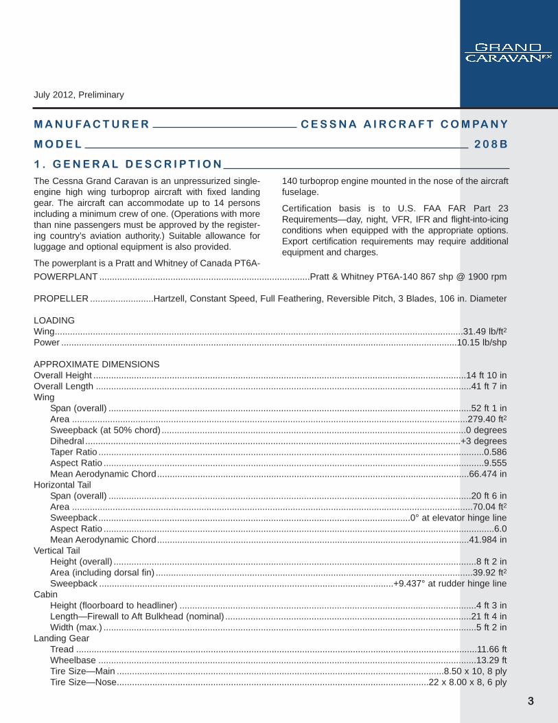
The Cessna Grand Caravan is an unpressurized single-engine high wing turboprop aircraft with fixed landinggear. The aircraft can accommodate up to 14 personsincluding a minimum crew of one. (Operations with morethan nine passengers must be approved by the register-ing country’s aviation authority.) Suitable allowance forluggage and optional equipment is also provided.
The powerplant is a Pratt and Whitney of Canada PT6A-
140 turboprop engine mounted in the nose of the aircraftfuselage.
Certification basis is to U.S. FAA FAR Part 23Requirements—day, night, VFR, IFR and flight-into-icingconditions when equipped with the appropriate options.Export certification requirements may require additionalequipment and charges.
POWERPLANT ...................................................................................Pratt & Whitney PT6A-140 867 shp @ 1900 rpm
PROPELLER .........................Hartzell, Constant Speed, Full Feathering, Reversible Pitch, 3 Blades, 106 in. Diameter
LOADINGWing.................................................................................................................................................................31.49 lb/ft2Power ............................................................................................................................................................10.15 lb/shp
APPROXIMATE DIMENSIONSOverall Height ...................................................................................................................................................14 ft 10 inOverall Length ....................................................................................................................................................41 ft 7 inWing
Span (overall) ...............................................................................................................................................52 ft 1 inArea ............................................................................................................................................................279.40 ft2Sweepback (at 50% chord) ........................................................................................................................0 degreesDihedral ....................................................................................................................................................+3 degreesTaper Ratio ........................................................................................................................................................0.586Aspect Ratio ......................................................................................................................................................9.555Mean Aerodynamic Chord...........................................................................................................................66.474 in
Horizontal TailSpan (overall) ...............................................................................................................................................20 ft 6 inArea ..............................................................................................................................................................70.04 ft2Sweepback...........................................................................................................................0° at elevator hinge lineAspect Ratio ..........................................................................................................................................................6.0Mean Aerodynamic Chord...........................................................................................................................41.984 in
Vertical TailHeight (overall) ...............................................................................................................................................8 ft 2 inArea (including dorsal fin) .............................................................................................................................39.92 ft2Sweepback ....................................................................................................................+9.437° at rudder hinge line
CabinHeight (floorboard to headliner) .....................................................................................................................4 ft 3 inLength—Firewall to Aft Bulkhead (nominal) .................................................................................................21 ft 4 inWidth (max.) ...................................................................................................................................................5 ft 2 in
Landing GearTread ..............................................................................................................................................................11.66 ftWheelbase .....................................................................................................................................................13.29 ftTire Size—Main .................................................................................................................................8.50 x 10, 8 plyTire Size—Nose...........................................................................................................................22 x 8.00 x 8, 6 ply
4
2 . P E R F O R M A N C E
1 . G E N E R A L D E S C R I P T I O N ( C o n t i n u e d )DESIGN WEIGHT AND CAPACITIES
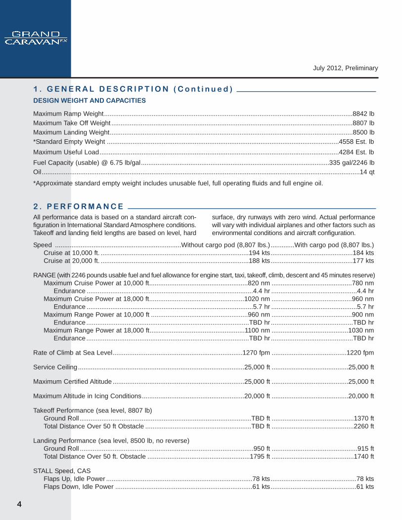
Maximum Ramp Weight........................................................................................................................................8842 lbMaximum Take Off Weight ....................................................................................................................................8807 lbMaximum Landing Weight.....................................................................................................................................8500 lb*Standard Empty Weight ...............................................................................................................................4558 Est. lbMaximum Useful Load...................................................................................................................................4284 Est. lbFuel Capacity (usable) @ 6.75 lb/gal.......................................................................................................335 gal/2246 lbOil..............................................................................................................................................................................14 qt
*Approximate standard empty weight includes unusable fuel, full operating fluids and full engine oil.
All performance data is based on a standard aircraft con-figuration in International Standard Atmosphere conditions.Takeoff and landing field lengths are based on level, hard
surface, dry runways with zero wind. Actual performancewill vary with individual airplanes and other factors such asenvironmental conditions and aircraft configuration.
Speed .....................................................................Without cargo pod (8,807 lbs.).............With cargo pod (8,807 lbs.)Cruise at 10,000 ft. .................................................................................194 kts.............................................184 ktsCruise at 20,000 ft. .................................................................................188 kts.............................................177 kts
RANGE (with 2246 pounds usable fuel and fuel allowance for engine start, taxi, takeoff, climb, descent and 45 minutes reserve)Maximum Cruise Power at 10,000 ft......................................................820 nm ............................................780 nm
Endurance ...........................................................................................4.4 hr ...............................................4.4 hrMaximum Cruise Power at 18,000 ft....................................................1020 nm ............................................960 nm
Endurance ...........................................................................................5.7 hr ...............................................5.7 hrMaximum Range Power at 10,000 ft .....................................................960 nm ............................................900 nm
Endurance .........................................................................................TBD hr .............................................TBD hrMaximum Range Power at 18,000 ft....................................................1100 nm ..........................................1030 nm
Endurance .........................................................................................TBD hr .............................................TBD hr
Rate of Climb at Sea Level.......................................................................1270 fpm .........................................1220 fpm
Service Ceiling ...........................................................................................25,000 ft ..........................................25,000 ft
Maximum Certified Altitude ........................................................................25,000 ft ..........................................25,000 ft
Maximum Altitude in Icing Conditions........................................................20,000 ft ..........................................20,000 ft
Takeoff Performance (sea level, 8807 lb)Ground Roll..............................................................................................TBD ft .............................................1370 ftTotal Distance Over 50 ft Obstacle ..........................................................TBD ft .............................................2260 ft
Landing Performance (sea level, 8500 lb, no reverse)Ground Roll ...............................................................................................950 ft ...............................................915 ftTotal Distance Over 50 ft. Obstacle ........................................................1795 ft .............................................1740 ft
STALL Speed, CASFlaps Up, Idle Power ................................................................................78 kts...............................................78 ktsFlaps Down, Idle Power ...........................................................................61 kts...............................................61 kts
July 2012, Preliminary
July 2012, Preliminary
5
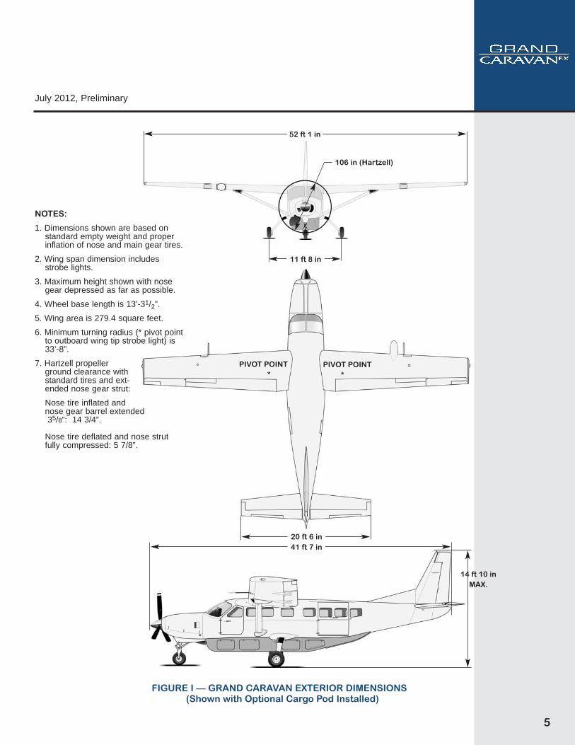
(Shown with Optional Cargo Pod Installed)
52 ft 1 in
106 in (Hartzell)
11 ft 8 in
20 ft 6 in
PIVOT POINT*
PIVOT POINT*
14 ft 10 inMAX.
41 ft 7 in
FIGURE I — GRAND CARAVAN EXTERIOR DIMENSIONS
NOTES:
1. Dimensions shown are based onstandard empty weight and properinflation of nose and main gear tires.
2. Wing span dimension includesstrobe lights.
3. Maximum height shown with nosegear depressed as far as possible.
4. Wheel base length is 13’-31/2”.
5. Wing area is 279.4 square feet.
6. Minimum turning radius (* pivot pointto outboard wing tip strobe light) is33’-8”.
7. Hartzell propeller ground clearance with standard tires and ext-ended nose gear strut:
Nose tire inflated and nose gear barrel extended35/8”: 14 3/4”.
Nose tire deflated and nose strutfully compressed: 5 7/8”.
6
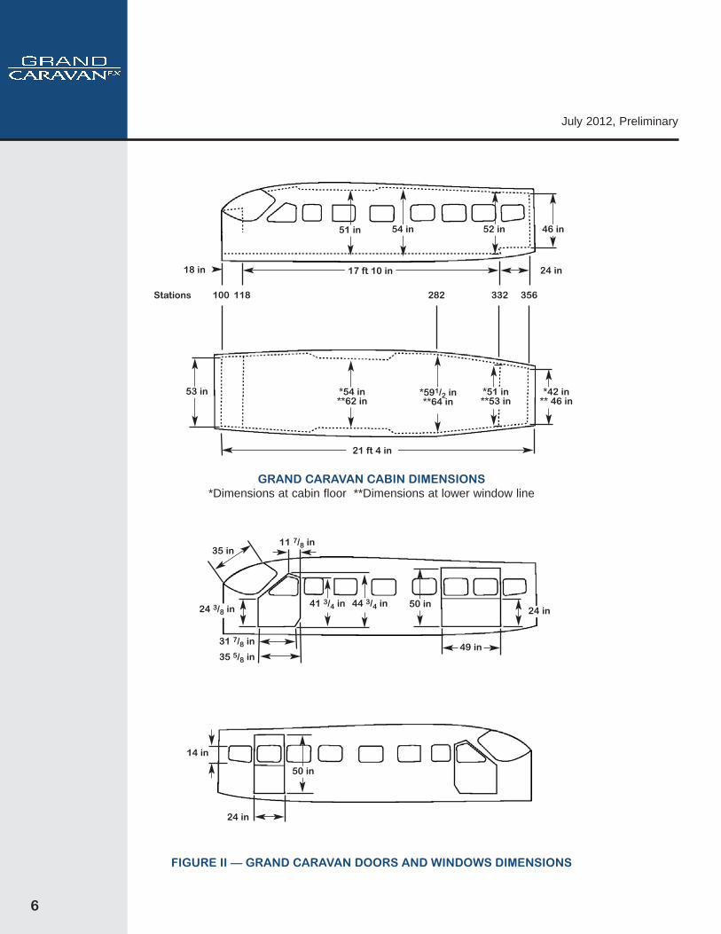
51 in 54 in 52 in
*51 in**53 in
*54 in**62 in
*591/2 in**64 in
46 in
Stations
FIGURE II — GRAND CARAVAN DOORS AND WINDOWS DIMENSIONS
GRAND CARAVAN CABIN DIMENSIONS*Dimensions at cabin floor **Dimensions at lower window line
*42 in** 46 in
53 in
17 ft 10 in
118 100 282 332 356
24 in 18 in
50 in
24 in
50 in24 in
14 in
49 in
41 3/4 in 44 3/4 in24 3/8 in
31 7/8 in
11 7/8 in
35 5/8 in
35 in
21 ft 4 in
July 2012, Preliminary
July 2012, Preliminary
7
4 . F U S E L A G E G R O U P
3 . S T R U C T U R A L D E S I G N C R I T E R I A
The Grand Caravan certification basis is to FAR Part 23normal category aircraft.
Design limit load factors are +3.8G, -1.52G at a maxi-mum takeoff weight of 8,750 pounds. Ultimate loads aredefined as 1.5 times the limit loads.
DESIGN SPEEDS(All speeds are at maximum gross weight.)
Cruising Maximum Operating Limit (VMO)........................................................................................................175 KCAS
Flap Extension Speeds (VFE)0° to 15° .....................................................................................................................................................150 KCAS15° to 30° ...................................................................................................................................................125 KCAS
Maneuvering Speed (VA)8807 pounds ..............................................................................................................................................148 KCAS7500 pounds ..............................................................................................................................................137 KCAS6250 pounds ..............................................................................................................................................125 KCAS5000 pounds...............................................................................................................................................112 KCAS
Construction of the fuselage is of conventional formedsheet metal bulkhead, stringer and skin design. Majorelements of the structure are the front carry-through sparand bulkhead, the rear carry-through spar and landinggear bulkhead, and the forward doorpost. The frontcarry-through spar and bulkhead is an integral fail-safestructure with forgings at the top for attaching the frontwing spar and forgings at the bottom for attaching thewing strut. The rear carry-through and landing gear bulk-head is an integral fail-safe structure with forgings at thetop for attaching the rear wing spar and forgings at thebottom for attaching the main landing gear trunnions.The forward doorpost provides the load path for trans-ferring the loads from the engine mount directly to theprimary structure.
The large cabin area provides comfortable space for apilot and up to thirteen passengers. (Operations withmore than nine passengers are limited to countries thatissue approval.) Inside cabin dimensions are 51" highand 62" wide at the front and rear spar bulkhead loca-tions. The cabin narrows slightly toward the tailcone to52" high and 53" wide just aft of the cargo door. Totallength of the cabin from the firewall to the aft bulkhead is21 ft. 4 in. The cabin floor is flat with the exception of twofeet in the aft cabin which is five inches above the mainfloor and makes up the aft cabin baggage area.
Cabin volume, including the pilot and aft cabin baggage
area is 427 cubic feet. Total volume aft of the pilot and frontpassenger seat locations is approximately 340 cubic feet.
Entry to, and exit from the airplane is accomplishedthrough an entry door on each side of the cabin at the pilotand front passenger seat location and through a two pieceairstair-type door on the right side of the airplane just aftof the wing. A large cargo door is also provided on the leftside of the airplane directly across from the airstair door.All doors can be opened with the flaps up or down.
The left crew entry door incorporates a conventionaldoor handle, key-operated Medco door lock, conven-tional interior door handle and window with a small tri-angular foul weather window. The foul weather windowmay be opened for additional ground ventilation. Theright crew entry door incorporates a conventional out-side and inside door handle and a manually operatedinside door lock. A 4 inch deep x 5 1/2 inch Kydex stor-age area is incorporated into the interior width of boththe left and right crew doors. Both doors have a maxi-mum width of 35.65 inches and a maximum height of44.75 inches and will open 180 degrees forward to latchagainst the side of the fuselage.
The passenger entry door consists of an upper and lowersection. When opened, the upper section swings upwardand the lower section drops down providing integral stepsto aid in boarding or exiting the airplane. The door open-ing is approximately 24 inches wide and 50 inches high.
8
The empennage consists of a conventional vertical stabi-lizer, rudder, horizontal stabilizer and elevator, all of whichare constructed of a forward and aft spar with formedsheet metal ribs and aluminum skin panels. The horizon-tal stabilizer contains dual jack screw type actuators for
operating the elevator trim tabs. An elevator trim tab isattached to each elevator by full length piano-typehinges. Stabilizer abrasion boots are installed along theleading edge of the horizontal stabilizer.
The primary opening is the two-piece cargo door installedon the left side of the airplane aft of the wing trailing edge.The cargo door is divided into an upper and lower section.When opened, the upper section swings upward and thelower section opens 180 degrees forward providing alarge 49 inch wide by 50 inch high opening in the side ofthe fuselage which facilitates the loading of bulky cargointo the cabin. The door opening is flush with the floor andhas square corners for maximum cargo loading capability.
The airplane is equipped with a two-piece plexiglasswindshield reinforced with a metal center strip. Sixteenside windows of the fixed type are installed in the cabinsides including one each in the two crew entry doors,two windows in the upper section of the cargo door andone window in the upper section of the passenger entrydoor. The windshield and forward crew door windowsare 5/16 inch and 1/4 inch thick respectively. All otherwindows are 3/16 inch thick tinted plexiglass.
6 . E M P E N N A G E G R O U P
4 . F U S E L A G E G R O U P ( C o n t i n u e d )
7 . L A N D I N G G E A RThe landing gear is of the non-retracting, tricycle typewith a steerable nose wheel and two main wheels.Shock absorption is provided by the tubular spring steelmain landing gear struts with an inter-tube connectingthe two outer tubes. The tires are tube type; standardnose tire is 22 x 8.00 x 8, 6 ply and main gear tires are8.50 x 10, 8 ply. The nose gear tire is mounted on anextended nose gear strut providing 14 3/4 in. groundclearance. The nose gear shock absorption is providedby the oil snubber combined with a drag link spring pro-
viding vertical and aft displacement restraint. Each maingear wheel is equipped with a hydraulically actuated fourpiston brake.
Nose gear steering is accomplished by using the rudderpedals which turns the nose wheel through an arc ofapproximately 15° each side of center. By applying eitherleft or right brake, the degree of turn may be increased upto 51.5° each side of center. The minimum turning radiusof the airplane, using differential braking and nose wheelsteering during taxiing, is 33 feet 8 inches.
8 . P R O P U L S I O N
8.1 Powerplant
The propulsion system consists of a single fuselagemounted Pratt and Whitney PT6A-140 turboprop engine.The PT6A-140 is rated to 867 shp at 1900 rpm. Timebetween overhaul for this engine is 3600 hours.
Conventional turboprop controls are used to operate theengine and propeller. They consist of a power lever,emergency power lever, propeller control lever and a fuelcondition lever. The power and fuel condition levers areengine controls while the propeller control lever controls
propeller speed. An emergency power lever is providedto manually control fuel supply to the engine should amalfunction occur in the fuel control unit.
Engine operation is monitored by the engine indicationsystem (EIS) which shows numeric readouts of criticalengine, fuel and electrical indications for the following:torque, propeller speed, interstage temperature (ITT),gas generator % RPM (Ng), fuel flow, oil pressure andoil temperature. A wet type standby engine torquegauge is also installed. Engine torque is limited by a sen-sor that reduces fuel flow if an over torque occurs.
5 . W I N G G R O U PThe Grand Caravan utilizes conventional wings withNACA 23000 Series Airfoils. The externally braced, fail-safe wings are constructed of front and rear spars withformed sheet metal ribs, doublers and stringers. Theentire structure is covered with aluminum skin.
The primary wing spars, wing carry-through spars in thefuselage and attaching structure are of fail-safe construc-tion for limit flight loads. Fail-safe construction assuresthat the structure is designed and built in such a way thatshould any single structural component fail, the remainingstructure is capable of carrying certified limit flight loads.
July 2012, Preliminary
July 2012, Preliminary
9
9.1 Flight Controls
The Grand Caravan’s flight control system consists ofconventional aileron, elevator and rudder control sur-faces. In addition, a pair of slot lip spoilers are mountedabove the outboard ends of the flaps. The control sur-faces are manually operated through mechanical link-age using a control wheel for the ailerons, spoilers andelevator and rudder/brake pedals for the rudder.
The rudder control utilizes a rudder pedal cable systemdriving the rudder. The floor mounted rudder bars aregear interconnected to maintain cable tension.Conventional design of inner torque tubes serve to allowco-pilot operation of the left-hand mounted brake cylin-ders. The brake cylinders have a remote reservoirmounted on the forward side of the engine firewall forconvenient access.
Rudder trim system consists of a trim wheel driving a flexshaft which, in turn, adjusts rudder pressure.
The elevator control system features a conventionalcable drive system. The elevator is connected to thecables by a bellcrank and push-pull rod.
Elevator trim is accomplished through two elevator trimtabs by utilizing the vertically mounted trim control wheelon the control pedestal. An electric elevator trim system
is available with the standard autopilot installation.
The aileron control system is a combination of cables,quadrants, bellcranks and push-pull rods. A push-pullrod drives the ailerons.
An aileron trim system consists of a pedestal mountedcontrol knob, cables, fail-safe actuator, pushrods andtrim tabs. The left aileron incorporates a servo tab whilethe right aileron incorporates a trimmable servo tab.
A pair of slot lip spoilers mounted above the outboardends of the flaps are incorporated to improve low speedroll control. The spoilers are interconnected with theaileron system through a pushrod mounted to an arm onthe aileron bellcrank. Spoiler travel is proportional toaileron up travel.
The single slotted, semi-fowler flaps are electrically drivenand incorporate a trailing edge angle with leading edge vor-tex generators to reduce stall speed and provide enhancedlateral stability. A selector and mechanical type follow-upindicator is provided in the control pedestal. The flap systemconsists of an electrically driven screwjack actuator, a pri-mary and standby motor, and a system of cables, bell-cranks and pushrods connected to the flaps. The standbyelectric drive motor provides a back-up flap actuation sys-tem in the event of failure of the primary motor.
9 . S Y S T E M S
8 . P R O P U L S I O N ( C o n t i n u e d )An inertial separator system is built into the engine airinlet duct to prevent moisture particles from entering theengine inlet plenum. The inertial separator system ismechanically controlled by a push-pull handle located onthe left side of the instrument panel. Engine ignition isprovided by two igniters that are energized by a dualchannel ignition exciter mounted on the right side of theengine compartment.
Engine ignition is provided by two igniters that are ener-gized by the ignition exciter mounted on the right side ofthe engine compartment. Mounting provisions are pro-vided for a standby ignition exciter unit.
An Altair Digital ADAS - P & WC FAST Engine TrendMonitor is an engine trend recording device and anengine parameter exceedance monitor which will allowoperators to monitor the health of the engine throughperiodic sampling of engine parameters. The enginetrend monitor contains logic to determine when the air-craft is in a stable cruise flight regime before automati-
cally taking a trend sample. The data is automaticallyuploaded via built-in cell phone transmitter after landing.
This is an advisory system only. The airplane’s engine indi-cation system is still the primary source of detecting andcorrecting conditions where engine limitations are exceed-ed. There are no additional aircraft limitations and no per-formance change with the P & WC FAST Engine TrendMonitor installed.
8.2 Propeller
The Grand Caravan is equipped with a 106 inch diame-ter metal propeller. The three-blade, anti-ice, constantspeed, full feathering, single acting, reversible pitch pro-peller is manufactured by Hartzell, model HC-B3TN-3AF(Y). The propeller is controlled by a propeller gover-nor and an overspeed governor mounted on and drivenby the reduction gear-box. The overspeed governor actsas a safeguard against propeller overspeed should theprimary propeller governor fail.
10
July 2012, Preliminary
9 . S Y S T E M S ( C o n t i n u e d )9.2 Fuel System
The Grand Caravan fuel system consists of two ventedintegral fuel tanks (one in each wing formed by the frontand rear spars), a fuel reservoir, engine fuel system,quantity and flow instrumentation, and the necessarylines, controls, valves and pumps to complete the sys-tem. Fuel system capacity is 338.9 U.S. gallons (335gallons usable). Filling the fuel tanks is accomplishedthrough filler caps in each wing.
Normal operation is with both tanks on. The pilot canmechanically select fuel from either left or right fuel tanksor both at the same time.
Fuel quantity is measured by four fuel level probes (two ineach wing tank) and indicated on the engine indicationsystem (EIS). The fuel quantity system is calibrated in gal-lons based on 6.7 pounds per gallon. Fuel quantity indi-cations are displayed in pounds. Wing fuel level cautionadvisories, one for each wing tank, are provided throughthe crew advisory system (CAS). The appropriate FUELLOW (CAS) message will illuminate when the fuel in therespective tank is approximately 25 gallons or less. Awarning advisory is also provided to indicate a low fuellevel in the fuel reservoir tank.
9.3 Electrical System
The Grand Caravan is equipped with a 28-volt, direct-current electrical system. The system uses a 24-volt, 38ampere-hour sealed lead acid battery as a source ofelectrical energy and a 200-amp engine-driven startergenerator. (An optional 300-amp engine-driven startergenerator is available.) Power is supplied to most gen-eral electrical and all avionics circuits through two gen-eral buses, two avionics buses and a battery bus. Thebattery bus is energized continuously for ELT reset,clock, cabin/courtesy light functions and engine trendmonitor processor.
A generator control unit provides the electrical control func-tion necessary for the operation of the starter-generator.
Electrical system operation can be monitored on theEngine Indication System (EIS) display on the MFD (innormal mode). Battery Amps and Battery Volts can beviewed on either EIS page (Engine or System). Generatorand (Standby) Alternator Amps can be viewed on the EISSystem page. The Crew Alerting System (CAS)Annunication Window is located on each Primary FlightDisplay (PFD) and can present appropriate messages (i.e.warning, caution and advisory) pertaining to variousengine and aircraft systems as may be applicable.
A standard ground service plug receptacle permits theuse of an external power source for cold weather start-ing or during maintenance work. Ground service circuit-ry is provided to prevent the external power and the bat-tery from being connected together during starting, andincorporates polarity reversal and overvoltage protec-tion. The external power receptacle is installed on the leftside of the engine compartment near the firewall.
A standby electrical system is installed for use as a stand-by power source in the event the main generator systemmalfunctions in flight. The system includes a belt-drivenalternator operated at a 75-amp capacity rating.
One automotive-style 12-volt power outlet is located inthe cockpit. Two cabin power outlets in the passengerarea are available as an option.
An optional 115VAC inverter is available with outletsbehind the pilot and copilots doors and two additionaloutlets on either side midway of the cabin. A total of 500Watts is available combined between the four outlets.
9.4 Lighting System
Exterior LED lighting consists of two navigation lights,two landing lights, two taxi/recognition lights, two strobelights, a flashing beacon and two underwing courtesylights. All exterior lights are controlled by toggle switcheslocated on the lighting control panel on the left side ofthe instrument panel.
The G1000 instrument panel incorporates LED back-lighting controlled manually through the instrument paneldimmer bus. When the dimmer bus is not used, photo-cell technology automatically controls backlight adjust-ments to optimize display appearance through a broadrange of cockpit lighting conditions. Other miscellaneouslighting provided include pilot and co-pilot control wheelmap lights, cabin/courtesy lights, passenger readinglights and a no smoking/seat belt advisory sign. All inte-rior lighting is LED with the exception of pilot and copilotcontrol wheel map lights.
9.5 Environmental System
The temperature and volume of airflow to the cabin isregulated by the cabin heating, ventilating and defrostingsystem. In the heating system, hot engine compressoroutlet air is routed through system components to obtainthe correct air temperature before air is routed to thecabin air distribution system. Controls are provided todirect the heated air to the forward and/or aft portions ofthe cabin for heating and to the windshield for defrosting.
July 2012, Preliminary
11
Outside ventilating air is obtained from an inlet on eachside of the forward fuselage and through two ram airinlets, one on each wing at the upper end of the wingstruts. The wing ventilating air is routed through the winginto a plenum chamber located in the center of the cabintop. The plenum distributes the ventilating air to individ-ual overhead outlets at each seat position. The forwardfuselage ram air inlets provide ventilation through paneloutlets to the flight deck.
A fan driven ventilation system provides supplementalcabin ventilation through two overhead mounted ventila-tors. An optional air conditioning system is available thatprovides comfortable cabin temperataures during hotweather operations, both on the ground or in flight.
Optional seventeen and ten port oxygen systems areavailable.
9.6 Pitot-Static System
The left hand pitot-static system supplies ram air and stat-ic pressure to the number one ADC (Air Data Computer)and to the standby airspeed indicator. It also provides stat-ic pressure to the standby altimeter. The system is com-posed of a heated pitot-static tube mounted on the lead-ing edge of the left wing, a static pressure alternate sourcevalve, a drain valve located behind the instrument paneland the associated plumbing necessary to connect theinstruments and sources.
The right hand pitot-static system supplies ram air andstatic pressure to the number two ADC. The system iscomposed of a heated pitot-static tube mounted on theleading edge of the right wing, a drain valve locatedbehind the instrument panel, and associated plumbing.
9.7 Vacuum System
A vacuum system provides the suction necessary tooperate the standby attitude indication. Vacuum isobtained by passing regulated compressor bleed airthrough a vacuum ejector. The vacuum system consistsof the bleed air pressure regulator, a vacuum ejector, avacuum relief valve, and a vacuum system air filter. Thesystem is monitored via a warning flag on the standbyattitude indicator.
9.8 Garmin G1000 Avionics System
The integrated avionics system incorporates 3 ten-inchdisplays; the pilot’s primary flight display (PFD), the mul-tifunction display (MFD) and the co-pilot’s PFD. The sys-tem includes a single audio system control panel and aseparate autopilot controller.
The fully integrated Garmin G1000 system will providethe following communication/navigation/surveillance(CNS) functions: Dual VHF NAV/Glideslope/Localizerreceivers, dual VHF com transceivers, dual WAAS GPSreceivers and Mode S Transponder. The KN-63 DME isan integrated display and offers Nav1/NAV2 switiching.Crew alerts are displayed on the PFDs.
The automatic flight control system (AFCS) incorporatesa GFC-700 three-axis autopilot with pitch trim and GFC-710 autopilot controller.
Avionics cooling is provided by two cowl deck fans andthree display fans. The cowl deck fans are powered fromthe electrical bus. The display fans provide cooling air toeach of the three display units and are powered from thedisplay power circuits.
Avionic circuit breakers are located on an exclusivepanel located on the lower left-hand instrument panel.
1 0 . C O R R O S I O N P R O O F I N G
The Grand Caravan includes corrosion proofing as stan-dard equipment. Detail parts receive a chemical film con-version coating and are epoxy primed.
Interior surfaces of integral wing fuel bays are primedwith a fuel resistant epoxy primer for corrosion protection.
Steel parts in contact with aluminum structure, in gener-al, are cadmium-plated with a chromate dip. Fasteners
utilized in the joining process of the steel to aluminumassemblies are installed wet primed for improved corro-sion protection.
The engine mount structure receives a heat resistantenamel finish providing protection in thermal environ-ments up to 400° F.
Polyurethane paint is included as standard exterior paint.
9 . S Y S T E M S ( C o n t i n u e d )
12
July 2012, Preliminary
11.1 AVIONICS
Standard Avionics Kit (includes Two Headsets)Garmin G1000 System includes:GDU 1040A Pilot & Co-Pilot Primary Flight Display (PFD)GDU 1040A Multi Function Display (MFD)GDC 74A Dual Air Data Computer (ADC)GEA 71 Engine/Airframe UnitGIA 63W Integrated Avionics UnitsGRS 77 Dual Attitude and Heading Reference System
(AHRS)GMA 1347 Single Audio System with Integrated Marker
Beacon ReceiverGMC 710 Autopilot Mode ControllerGSA 80/81 Servo ActuatorsGTX 33 Mode S TransponderGarmin Relative Terrain/ObstaclesGarmin Flight Charts CapableGarmin Safe Taxi CapableKN-63 DMESwitch, Avionics Power (Two) (On-Off)
Artex ME-406 2-Frequency (Non -Nav Interfaced) ELT withRemote Switch and Monitor Light (Dorsal FinInstallation)
Avionics Cooling, (2) cowl deck fans and (3) display fansPA System with Aft Cabin Speakers
11.2 ENGINE INDICATION SYSTEM (EIS)Displayed on MFD During Normal Operations:
Engine and System Displays - Show numeric readouts of criti-cal engine, fuel and electrical indications and calculations forthe following:
Torque Interstage Turbine Temperature Gas Generator Speed Propeller SpeedOil Pressure Oil Temperature Fuel QuantityFuel FlowAmmeter/Voltmeter
1 1 . S TA N D A R D G R A N D C A R A V A N E Q U I P M E N T
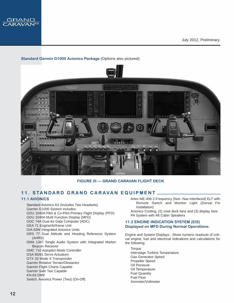
Standard Garmin G1000 Avionics Package (Options also pictured)
FIGURE III — GRAND CARAVAN FLIGHT DECK
July 2012, Preliminary
13
1 1 . S TA N D A R D G R A N D C A R A V A N E Q U I P M E N T ( C o n t i n u e d )Standby Engine InstrumentEngine Torque Gauge, Wet Type
Digital FAST Engine Trend Monitoring System
11.3 FLIGHT INSTRUMENTS
Indications Displayed on each PFD:AirspeedAttitude with Slip/Skid IndicationAltitudeVertical Deviation, Glideslope and Glidepath Vertical Speed Horizontal Situation IndicationOutside Air TemperatureSystem TimeGeneric TimerWind Data
Standby Flight Instruments:Airspeed IndicatorAttitude GyroAltimeter
Magnetic Compass, Heated Pitot System, Pilot & Co-PilotAlternate Static SourceStatic Source DrainsInstrument Static SystemSecond Indpendent Pitot-Static System
11.4 FLIGHT CONTROLS
Brake, ParkingBrakes, Hydraulic, Toe-OperatedControl Cables — Corrosion Resistant SteelControl Lock, Ailerons and ElevatorFlight Control System, Pilot & Co-Pilot (Includes All-
Purpose Control Wheel, Pedals and Toe Brakes)Friction Lock, Engine ControlsPowerplant, Quadrant Type Controls:
Condition LeverPrimaryEngine PowerBack-Up Engine Power, (Emergency Power Lever)
Propeller, Speed and FeatherRudder Gust LockTrim System (Aileron/Rudder (Manual), Elevator (Manual &
Electric Pilot & Co-Pilot)Wing Flaps, Electric Pre-Select with Standby Motor
11.5 ENVIRONMENTAL
Defroster, Windshield (Pilot and Copilot)Heating System, Cabin (Bleed Air Type)SoundproofingVentilation System, Cockpit (Ram Air)Ventilator, Adjustable, Cabin Air Ventilation System, Fan Driven
11.6 ELECTRICAL POWER
Battery, 24 Volt, 38 Amp/Hr, Sealed Lead-AcidBattery Switch (On-Off)Circuit Breakers, ElectricalGenerator Control UnitGenerator Switch (Trip-On-Reset)Ground Service Plug ReceptacleStarter/Generator, 200 AmpGenerator Control Unit Mounting (Provisions for Mounting
Standby Unit)Power Outlet, 12V CockpitStandby Electrical System, 75 amp
11.7 EXTERIOR LIGHTS (LED)
Beacon – Omni Flash (Red)Courtesy, Under WingLanding, L.H. and R.H. (Wing Leading Edge-Outboard)Navigation (2)Strobe (2) Wing Tip MountedTaxi, L.H. and R.H. (Wing Leading Edge-Inboard)Ice Detection
11.8 INTERIOR LIGHTS (LED)
LED Backlit Instrument Panel LightingMap Light, Control Wheel Mounted, Pilot & Co-Pilot
(Variable Intensity)Overhead Courtesy (4) (Forward and Mid Cabin, Cargo
Door and Passenger Door)Overhead Flood (Pilot and Copilot) (3)Passenger Reading Lights (14)Dimming Controls, Switch Panel, Avionics Circuit Breaker
Panel, Left Hand Panel & Environmental Panel
11.9 POWERPLANT
Chip Detector InstallationCowling, Rigid-Mounted (Quick Removable) Lower and
Easily Openable Upper SidesCowl Locks, MedcoEngine Inlet Cover (2) and Propeller Tie-Down Sleeve Engine, Turboprop PT6A-140, 867 SHP, 3600 TBOEngine Wash Ring (Integral)Engine Support, Vibration IsolationFilter, Integral, Full Flow OilFire Detection System, Engine CompartmentIgnition System Exciter Unit Mounting (Provisions for
Mounting Standby Unit)Ignition System (Dual Ignitors)Intake Inertial Separator (Manual)Oil Cooler, High CapacityOverspeed GovernorPropeller, 3 Blade Aluminum, Constant Speed, Full
Feathering, Reversible – HartzellPropeller GovernorPropeller Spinner (Polished)
14
July 2012, Preliminary
1 1 . S TA N D A R D G R A N D C A R A V A N E Q U I P M E N T ( C o n t i n u e d )Shielding, Engine IgnitionShutdown Fuel Collector, EngineValve, Oil Quick Drain Oil Sight Gage
11.10 FUEL SYSTEM
Fuel Boost Switch, AuxiliaryFuel Caps with Anti-Siphon DoorsFuel Control Heater, EngineFuel Filter with Quick DrainFuel Low Level Warning SystemFuel Pump, Auxiliary (Electric)Fuel Pump, EngineFuel Reservoir with Quick DrainFuel Selector ValvesFuel Shutoff ValveFuel TanksFuel Valves, Quick Drain (8)Fuel Vents, Non-IcingFuel Sampler Cup
11.11 INTERIOR
Aircraft Keys Approach Plate Holder, L.H. & R.H.Baggage Area Partition NetBaggage Tie-Down Straps (4)Beverage Cup Holders (Pilot and Copilot)Cargo Tie-Down Fittings Provisions Cargo Tie-Down Fittings (Baggage Area)Checklist, Pilot’s (Laminated)Corrosion Proofing, InternalCrew Door Storage Area RH, LHFire Extinguisher Cabin– Hand TypeFloor Covering, Lightweight VinylGlareshield, PaddedHandbook, Customer Care, Includes Engine/Flight Logs,
Warranty, Etc.Handbook, Pilot's OperatingHeadliner – VinylHooks, Clothes HangerInstrument Panel – Metal Map/Glove CompartmentOxygen System, Partial Installation (Consists of Difficult to
Install Plumbing)Pilot and Co-pilot Restraint – Integral 5 Point Lap and
Shoulder Harness with Inertial ReelPilot’s LH Pre-Flight Assist HandlePlotter, Weight & Balance (Cargo & Passengers)Pockets, Map and StorageRecorder, Flight HourSeats, Pilot & Copilot, Adjustable Fore, Aft and Vertical with
Articulating Recline and Arm RestSign, Fasten Seat Belts & No SmokingStep, Cabin Entrance, Retractable (RH & LH Crew Entry
Doors)
Sunvisors, RosenWindow, Foul Weather, Pilot DoorWindows Tinted All-Around
11.12 EXTERIOR
Anti-Precipitation Static KitBonding Straps, Control Surface (Aileron, Elevator and
Rudder)Cargo Pod Provisions with Twisted StackCorrosion Proofing, ExternalDoor, Cargo, Two-Piece (Left Side of Aircraft, with Upper
Door Unlocked Annunciator Light)Door, Copilot (Full Opening)Door, Pilot (Full Opening)Door, Passenger with Airstair Feature (Right Side of Aircraft
with Upper Door Unlocked Annunciator Light)Jack Points (Fuselage and Main Landing Gear)Landing Gear, Fixed, Nose, SteerableLanding Gear, Fixed, MainLock, Key-Operated (One Key Fits All Doors)Paint, All Over (Modified Polyurethane)Stabilizer Abrasion BootsStall Warning System, HeatedTailstandTires, Tube Type, with Extended Nose Gear Fork, Main
8.50 x 10, 8 plyTie-Down Rings, AircraftTow Bar
July 2012, Preliminary
15
U.S. Standard Airworthiness Certificate, FAA8100-2; ExportCertificate of Airworthiness, FAA8130-4 or SpecialAirworthiness Certificate FAA8130-7 as appropriate;
Equipment ListWeight and Balance ReportGarmin Cockpit Resource GuidePilot’s Operating ManualAbbreviated Procedures ChecklistLog Books (Aircraft and Engines)
Additional Miscellaneous Information ConcerningEngine and Airframe Support
Passenger Briefing CardsCessna CESCOM Instruction Manual
CESSNA TECHNICAL INFORMATION
Cessna makes available a complete system of manualsand catalogs for the operation and maintenance of theCaravan. All Cessna and related technical information islisted in the Cessna Customer Care Supplies andPublications Catalog.
Cessna manuals are kept current through periodic revi-sions. Aircraft operators and designated maintenancefacilities can receive these revisions by mail through asubscription service. The subscription is free for the firstyear to owners of new aircraft. A subscription fee ischarged thereafter.
The following manuals are provided on CD-ROM with thepurchase of a new Caravan:
Service Maintenance ManualIllustrated Parts CatalogWiring Diagram ManualStructural Repair ManualService BulletinsAvionics Wiring Diagram (custom diagram of the actual
avionic installation)
The following materials are provided by Pratt & WhitneyCanada:
Combined Engine Maintenance Manual & IllustratedParts Catalog CD
One set Engine Service Bulletins Including Spare PartsBulletins and Service Information Letters (Paper)
Free revision coverage for one yearService Bulletins are also available by on-line or e-mail
subscription at www.pwc.ca or through the Prattand Whitney Help Desk at (800) 268-8000.
CESSNA REVISION STATUS CHECKLIST
The Revision Status Checklist is used to verify that onlythe most current Cessna maintenance and aircraft oper-ation publications are in use. The checklist is availableby subscription and is revised every 90 days.
CESSNA OWNER ADVISORY
Cessna Owner Advisories provide owners of Cessna aircraftup-to-the-minute information about mandatory and benefi-cial service requirements and the latest in product improve-ments. Owner Advisories summarize new Service Bulletinsor Service Newsletters and indicate any action required bythe owner, the time required for the owner to comply, and theexistence of any associated "credit allowances."
Cessna Owner Advisories are mailed automatically toowners of U.S. registered Cessna aircraft using the latestname and address provided to the FAA. Owner Advisoriescan be mailed to a different address by request, providedthe subject aircraft is still covered by Cessna warranty.International owners of Cessna aircraft covered byCessna warranty receive Owner Advisories through acomplimentary subscription. After warranty expiration,international subscriptions are available, although a sub-scription fee will be charged. Revisions for the Pilot'sOperating Handbook and Pilot's Abbreviated Checklistand/or Log of Approved Supplements are included withthe Owner Advisory when applicable.
Cessna aircraft owners may register, for free, withCessnaSupport.com to obtain a login that allows accessto PDF versions of Service Bulletins and Newsletters.Weekly e-mail notification of released service informationis available with registration to the site.
1 2 . D O C U M E N TAT I O N A N D T E C H N I C A L P U B L I C AT I O N S
16
July 2012, Preliminary
1 3 . M A I N T E N A N C E P R O G R A M S CESCOM
Cessna will provide a computerized maintenance recordservice for one (1) full year from the date of delivery of aCessna Caravan to the purchaser.
This service will provide owners and operators with thereports necessary for the efficient control of maintenanceactivities. It will provide an accurate and simple method ofkeeping up with aircraft components, inspections, servicebulletins and airworthiness directives while providing per-manent aircraft records of maintenance performed.
Reports will be available which reflect the aircraft status,upcoming scheduled maintenance and a recap of theprevious month's reported maintenance activity. Semi-annual reports concerning projected annual mainte-nance requirements, component removal history andfleet-wide component reliability will also be available.
The on-line system is the standard service, however, apaper service is available at an additional charge. Theon-line system is accessible using a local computer withInternet capability. Data is electronically transferredthrough Internet connections between the customer andCessna on a regular basis to keep information up-to-date at both locations. In addition to the standardCESCOM reports, customer specific reports and main-tenance records can be generated at the local comput-er whenever the customer wishes.
CARAVAN INSPECTION PROGRAM
The Caravan Inspection Program is task based, integrat-ing all inspections into an easy to follow sequence. Thebenefits of the old Phase Card program are now availableto all customers.
Flight-Data Acquisition, Storage, and Transmission(FAST)
Cessna has chosen the FAST system as standardequipment on the Caravan to allow operators to easilymonitor and maintain the aircraft engine.
The FAST system records engine parameters, indicatedairspeed, pressure altitude, outside air temperature,flight hour meter, battery voltage, and the positions of theparticle separator, emergency power lever and bleed aircabin heat switch.
Data is uploaded to P&WC data analysis servers auto-matically by GSM cell phone signal upon landing. TheP&WC WebECT (tm) website formats the data into cus-tomized reports for use as analysis tools.
ENGINE CONDITION TREND MONITORING
Pratt & Whitney Canada developed this program for usewith the PT6A-140 engines installed in Caravan aircraft.This is a system of calculating and graphically present-ing recorded engine instruction indications. The record-ed indications are then mathematically adjusted for com-parison of actual engine performance to typical engineperformance characteristics.
Two important features are available to owners andoperators using engine trend monitoring:
1. It allows for early detection of compressor and/orturbine deterioration, thereby minimizing second-ary problems and overall repair costs.
2. It allows for hot section inspections to be accom-plished on an "on condition" basis instead of at ascheduled recommended 1800-hour intervalprovided the following requirements are met:
*Monitoring is implemented within the first 100hours in service or after completion of the hot sec-tion inspection
*Certain other requirements are met as stipulatedby Pratt & Whitney
"On condition" hot sections are hot sectionsaccomplished only when necessary, which resultsin significantly reduced operating costs.
Open Account Information
With an active open account, Caravan owners are ableto purchase spare parts at the current published list pricedirectly from Cessna Service Parts and Programs. Theopen account can also be used to purchase Cessnapublications and other items.
PRATT & WHITNEY ENGINE MAINTENANCE PROGRAMS
Fleet Services
The Fleet Services business unit offers “pay-by-the-hour”programs for both the airline and corporate markets. Theairline program is entitled Fleet Management Program(FMP®) while the corporate program is entitled EagleService Plan (ESP®). The objective of these programs isto establish a stable, simplified engine management andfinancial planning tool, which will guarantee operatingcosts tailored to suit individual requirements.
These programs provide predictability of costs associatedwith engine maintenance and minimize the effort required
July 2012, Preliminary
17
1 3 . M A I N T E N A N C E P R O G R A M S ( C o n t i n u e d )
for the operator to effectively manage its engines. Theseplans eliminate the risk of high cost surprises.
The programs currently offered include:
Term Cost Plan (TCP®)
Under the TCP® the operator pays a guaranteed hourlyrate on a monthly basis per engine flying hour. The rateis based on support services selected from a compre-hensive menu of options.
Event Cost Plan (ECP®)
As with the TCP®, the operator pays a guaranteed hourlyrate per engine flying hour. The payment occurs for eachindividual engine at the time of its shop visit, where thecharge is based upon the total engine hours flown by theengine since its last shop visit.
Maintenance Cost Guarantee Plan (MCG®) - Airline
The MCG® is a not to exceed cost guarantee. No monthly
payments are due. The operator covers the maintenanceexpenses as they occur and account reconciliation takesplace at agreed intervals. If the agreed hourly rate isexceeded, the overrun costs are settled in accordance withthe terms of the agreement. The operator retains the fullbenefit of any cost under runs.
Eagle Service Plan (ESP®)
Four plans are available for the corporate operatordepending on the level of coverage selected. P&WCprovides the operator with coverage of specified enginemaintenance expenses in return for a monthly paymentbased on an established rate per engine operating hour.
Once signed on, you will benefit from having a P&WCrepresentative dedicated to providing the essential coor-dination and support you expect.
Telephone Number: (450) 468-7681Fax Number (450) 468-3772
The standard Grand Caravan EX Aircraft LimitedWarranty which covers the aircraft, other than the Pratt& Whitney Canada (P&WC) engine and associatedengine accessories, the Honeywell avionics, and theHartzell propeller which are warranted separately, is setforth below. Cessna specifically excludes vendor sub-scription services and the availability of vendor serviceproviders for Optional and Customer RequestedEquipment (CRQ) from Cessna's Limited AircraftWarranty. Following Cessna's Limited Warranty, theengine and engine accessory warranty of P&WC, theavionics warranty of Honeywell, and the propeller war-ranty of Hartzell are set forth. All warranties are incorpo-rated by reference and made part of the PurchaseAgreement. All warranties are administered by Cessna'sWarranty Department.
14.1 CESSNA GRAND CARAVAN EX LIMITEDWARRANTY (LIMITED WARRANTY)
Cessna Aircraft Company ("Cessna") expressly warrantseach new Grand Caravan EX Aircraft (exclusive ofengine and engine accessories supplied by P&WC,avionics supplied by Honeywell, and the propeller sup-plied by Hartzell which are covered by their separatewarranties), including other factory-installed avionicsand other factory-installed optional equipment to be freefrom defects in material and workmanship under normal
use and service for the following periods after delivery:
(a) One (1) year unlimited hours OR two (2) years/1,000 hour limit on all aircraft components manufac-tured by Cessna;
(b) Five years or 5,000 operating hours, whicheveroccurs first, for Garmin avionics;
(c) One year for all Optional Avionics;
(d) One year for Actuators, Brakes, GCUs, StarterGenerators, Valves, Windshields, and Vendor itemsincluding engine accessories supplied by Cessna unlessotherwise stated in the Optional Equipment andSelection Guide;
(e) One year for CRQs, Interior Components, InteriorFurnishings, and Paint.
Any remaining term of this Limited Warranty is automat-ically transferred to subsequent purchasers of the air-craft.
Cessna's obligation under this Limited Warranty is limit-ed to repairing or replacing, in Cessna's sole discretion,with exchange, overhauled, or new parts, any part orparts which: (1) fail within the applicable warranty peri-od, (2) are returned at the warranty recipient's expenseto the facility where the replacement part is procured,
1 4 . L I M I T E D W A R R A N T I E S
18
July 2012, Preliminary
whether through Cessna Service Parts & Programs or aservice facility authorized by Cessna to perform serviceon the aircraft (collectively "Support Facility"), (3) areaccompanied by a properly executed claim form, and (4)are found by Cessna or its designee to be defective.
Replacement parts must be procured through a SupportFacility and are only warranted for the remainder of theapplicable original aircraft warranty period. A new war-ranty period is not established for replacement parts.The repair or replacement of defective parts under thisLimited Warranty will be made by a service facilityauthorized by Cessna to perform service on the aircraft("Authorized Service Facility") without charge to the war-ranty recipient for parts and/or labor for removal, instal-lation, and/or actual repair of such defective parts. Allexpedited freight, transportation expenses, importduties, customs brokerage fees, sales taxes, and usetaxes, if any, on such warranty repairs or replacementparts are the warranty recipient's sole responsibility.(Location of Authorized Service Facilities will be fur-nished by Cessna on request.)
This Limited Warranty applies to only items detailedherein which have been used, maintained, and operatedin accordance with Cessna and other applicable manu-als, bulletins, and other written instructions. However,this Limited Warranty does not apply to items that havebeen subjected to misuse, abuse, negligence, accident,or neglect; to items that have been installed, repaired, oraltered by repair facilities not authorized by Cessna; orto items that, in the sole judgment of Cessna, have beeninstalled, repaired, or altered by other than AuthorizedService Facilities contrary to applicable manuals, bul-letins, and/or other written instructions provided byCessna so that the performance, stability, or reliability ofsuch items are adversely affected. This LimitedWarranty does not apply to normal maintenance servic-es (such as engine adjustments, cleaning, control rig-ging, brake and other mechanical adjustments, andmaintenance inspections); or to the replacement of serv-ice items (such as brake linings, lights, filters, de-iceboots, hoses, belts, tires, and rubber-like items); or tonormal deterioration of appurtenances (such as paint,cabinetry, and upholstery), corrosion or structural com-ponents due to wear, exposure, and neglect.
WITH THE EXCEPTION OF THE WARRANTY OFTITLE AND TO THE EXTENT ALLOWED BY APPLIC-ABLE LAW, THIS LIMITED WARRANTY IS EXPRESS-
LY IN LIEU OF ANY OTHER WARRANTIES,EXPRESSED OR IMPLIED, IN FACT OR BY LAW,APPLICABLE TO THE AIRCRAFT. CESSNA SPECIFI-CALLY DISCLAIMS AND EXCLUDES ALL OTHERWARRANTIES, INCLUDING, BUT NOT LIMITED TO,ANY IMPLIED WARRANTY OF MERCHANTABILITYOR FITNESS FOR A PARTICULAR PURPOSE. THEAFOREMENTIONED REMEDIES OF REPAIR ORREPLACEMENT ARE THE ONLY REMEDIES UNDERTHIS LIMITED WARRANTY. CESSNA EXPRESSLYAND SPECIFICALLY DISCLAIMS ALL OTHER REME-DIES, OBLIGATIONS, AND LIABILITIES, INCLUDING,BUT NOT LIMITED TO, LOSS OF AIRCRAFT USE,LOSS OF TIME, INCONVENIENCE, COMMERCIALLOSS, LOSS OF PROFITS, LOSS OF GOODWILL,AND ANY AND ALL OTHER CONSEQUENTIAL ANDINCIDENTAL DAMAGES. CESSNA NEITHERASSUMES NOR AUTHORIZES ANYONE ELSE TOASSUME ON ITS BEHALF ANY FURTHER OBLIGA-TIONS OR LIABILITIES PERTAINING TO THE AIR-CRAFT NOT CONTAINED IN THIS LIMITED WAR-RANTY. THIS LIMITED WARRANTY SHALL BE CON-STRUED UNDER THE LAWS OF THE STATE OFKANSAS AND ANY DISPUTES AND/OR CLAIMSARISING THERFROM SHALL BE EXCLUSIVELYRESOLVED IN THE STATE AND/OR FEDERALCOURTS LOCATED IN WICHITA, KANSAS. THE PAR-TIES HERETO CONSENT TO PERSONAL JURISDIC-TION IN THE FORUM CHOSEN.
14.2 PRATT & WHITNEY CANADA INC.(Abbreviated New Engine Warranty)
Pratt & Whitney Canada Inc. (P&WC) warrants that eachnew PT6A-140 engine complete with installed acces-sories at time of delivery will be free from defects inmaterial and manufacture. P&WC's liability and pur-chaser's remedy under this warranty are limited to therepair or replacement at P&WC's option of goodsreturned to P&WC or to a location designated by P&WCwhich are shown to P&WC's reasonable satisfaction tohave been defective, provided that written notice ofdefect shall have been given by Purchaser to P&WC orits designee within one thousand (1,000) flying hoursafter delivery of the engine to the first user. The repair orreplacement of defective goods under the Warranty willbe made by P&WC or its designee without charge forparts or reasonable labor for removal, installation and/oractual repair of such defective goods, and reasonabletransportation charges, except import duties, sales or
1 4 . L I M I T E D W A R R A N T I E S ( C o n t i n u e d )
July 2012, Preliminary
19
1 4 . L I M I T E D W A R R A N T I E S ( C o n t i n u e d )
use taxes, if any, on replacement. Transportationcharges for the return of defective goods to P&WC or itsdesignee and their reshipment to Purchaser and the riskof loss thereof will be borne by P&WC.
THE FOREGOING WARRANTIES ARE EXCLUSIVEAND ARE GIVEN AND ACCEPTED IN LIEU OF ANYAND ALL OTHER WARRANTIES, EXPRESSED ORIMPLIED, INCLUDING WITHOUT LIMITATION THEIMPLIED WARRANTY OF MERCHANTABILITY ANDANY OBLIGATION, LIABILITY, RIGHT, CLAIM ORREMEDY IN CONTRACT OR TORT WHETHER ORNOT ARISING FROM P&WC'S NEGLIGENCE, ACTU-AL OR IMPUTED. THE REMEDIES OF THE PUR-CHASER FOR ANY BREACH OF WARRANTY SHALLBE LIMITED TO THOSE PROVIDED HEREIN TO THEEXCLUSION OF ANY AND ALL OTHER REMEDIESINCLUDING, WITHOUT LIMITATION, INCIDENTAL ORCONSEQUENTIAL DAMAGES. NO VARIATION OREXTENSION OF THE FOREGOING WARRANTIES,REMEDIES OR THIS LIMITATION WILL BE BINDINGUPON P&WC UNLESS APPROVED IN WRITING BY ADULY AUTHORIZED OFFICER OF P&WC.
The above abbreviated warranty is for the purposes ofthe Specification and Description. For complete detailsof the PT6A-140 engine warranty, please refer toP&WC's full PT6A-140 warranty policy.
14.3 HONEYWELLHoneywell/Bendix/King Warranty
A. General Aviation Avionic products manufactured byHoneywell/Bendix/King, General Aviation Division (col-lectively referred to herein as "Honeywell/Bendix/King")are warranted against defects in design, material orworkmanship caused by Honeywell/Bendix/King or itsauthorized agent(s) for the Warranty Period as definedin Paragraph (B) of this statement which occur undernormal and intended use and service, subject to all ofthe qualifications and conditions hereinafter stated.
1. Warranty coverage is only offered to purchaserswho make warranty registrations within eighteen(18) months of the product's factory shipping date.Demonstration or stock aircraft usage is restricted to100 hours service prior to warranty registration. Warranty coverage, therefore, may be unavailableor limited, depending upon the usage or time theproduct in question may have remained unsold in
the custody of the O.E.M. (Original EquipmentManufacturer), his agent, or the retail dealer, a mat-ter as to which the seller is expected to maintainaccurate records and provide same, upon demand,to any purchaser or Honeywell/Bendix/King.
2. Warranty coverage for products otherwise not eli-gible by reason of expiration of the eighteen (18)month period specified above may again becomeeligible for warranty protection, provided (a) thatwarranty registration occurs within thirty (30) monthsof the product's factory shipping date and (b) that theproducts are submitted to Honeywell/Bendix/Kingfor inspection and certification and then the promul-gated Honeywell/Bendix/King certification fee ispaid.
B. The Warranty Period for products shall begin upon thedate of delivery of the product to the purchaser and shallend two years thereafter.
C. Any product Honeywell/Bendix/King finds to be in vio-lation of the warranty as set out in Paragraph (A) hereof,at the option of Honeywell/Bendix/King, shall berepaired, replaced, or exchanged, in accordance withthe following procedures:
1. Products shall be returned to an authorizedHoneywell/Bendix/King Service Center orHoneywell/Bendix/King Regional Product SupportRepair/Overhaul Facility, with transportationcharges prepaid.
2. After correction, the products shall be returned tothe purchaser with surface transportation chargesprepaid, except for returns to purchasers in foreigncountries.
3. The risk of loss or damage to all products in tran-sit shall be borne by the party initiating the trans-portation of such products unless the purchasermakes a request for a specific mode of transporta-tion. In such case, the risk of loss and the cost ofshipment shall be borne by the purchaser.
All items repaired or replaced hereunder shall be war-ranted for the unexpired portion of the original WarrantyPeriod.
D. This warranty specifically excludes defects whichHoneywell/Bendix/King determines to be the result of:
20
July 2012, Preliminary
1. Abuse, accident, or misuse;
2. Contamination, negligence, tampering, or improp-er storage or maintenance;3. Repair or attempted repair by unauthorized per-sons or use of non- Honeywell/Bendix/King orunauthorized repair or replacement parts; or
4. Products not installed by an authorizedHoneywell/Bendix/King Installation Facility in accordance with the appropriate installation manual.
E. The Warranty as set out in paragraph (A) is the onlywarranty for Honeywell/Bendix/King General AviationAvionics Products and is in lieu of all other warrantiesexpress or implied, including the implied warranties ofmerchantability and fitness for a particular purposewhich are herewith expressly excluded and disclaimed.
F. The remedies as set out in Paragraph (C) hereof statethe entire liability of Honeywell/Bendix/King and consti-tute the sole and exclusive remedy of the purchaser.Honeywell/Bendix/King shall not be liable for any otherclaim, loss, or damage, including, but not limited to inci-dental, consequential, or other kinds of damageswhether based on contract, tort, negligence, or othertheory of product liability.
G. Honeywell/Bendix/King reserves the right to makedesign changes, additions to, and improvements in itsproducts without the obligation to install same in prod-ucts previously manufactured.
14.4 HARTZELL PROPELLER
A. COVERAGE PROVIDED
Products Other Than De-Ice BootsHartzell Propeller Inc. ("Hartzell") warrants to the originalretail purchaser (the "Purchaser") that it will repair orreplace defects in material or workmanship in the com-ponents of a product manufactured by Hartzell, otherthan a de-ice boot, for a period of one (1) year from thedate the product is first placed into service, or for the first1000 operating hours of use of the product, whicheveroccurs first, subject to the other terms and conditions ofthis limited warranty.
De-Ice BootsHartzell warrants to the Purchaser that it will repair orreplace defects in material or workmanship in the com-ponents of a de-ice boot manufactured by Hartzell, for aperiod of eighteen (18) months from the date the de-ice
boot is first placed into service, or for the first 2000 oper-ating hours of use of the product, whichever occurs first,subject to the other terms and conditions of this limitedwarranty.
All of the products identified above are hereinafterreferred to as the "Products," and their componentshereinafter referred to as "Components."
B. DISCLAIMER OR LIMITATION OF WARRANTIES
Unless prohibited by applicable law, and except forthe limited warranties set forth above, Hartzell here-by disclaims any and all express and implied war-ranties, including but not limited to implied war-ranties of merchantability and fitness for a particularpurpose. In the event disclaimer of implied war-ranties is not permitted under applicable law, suchimplied warranties, including but not limited toimplied warranties of merchantability and fitness fora particular purpose, are limited in duration and inscope of coverage to the duration and scope of cov-erage of the limited warranty.
Some states do not allow limitations on how long animplied warranty lasts, so above limitation may notapply to you.
C. TERMS AND CONDITIONS OF LIMITED WARRANTYCOVERAGE
In order to obtain coverage under Hartzell's limited war-ranty, the Purchaser must notify Hartzell in writing of thewarranty claim as soon as possible after obtainingknowledge of the potential claim, and in any event notlater than ten (10) days following expiration of the limit-ed warranty. Hartzell may withhold warranty repairspending proof from Purchaser of the date the Productwas placed into service, including a fully completed war-ranty registration card. Hartzell shall provide warrantyrepair or disposition instructions based on a writtenstatement from the Purchaser describing the allegeddefect. All initial transportation and handling chargesmust be prepaid by the Purchaser until warrantability isdetermined by Hartzell, at which time Hartzell may reim-burse none, some, or all of these charges, at Hartzell'sdiscretion. In the event Hartzell determines, at its solediscretion, that the Product or Component thereof is cov-ered under the limited warranty, Hartzell shall, at its elec-tion, either:
1 4 . L I M I T E D W A R R A N T I E S ( C o n t i n u e d )
July 2012, Preliminary
21
(1) Have the Product or Component repaired andreturned to Purchaser;
(2) Deliver to Purchaser a replacement Product orComponent; or
(3) Issue a credit to the Purchaser in the amount ofthe actual purchase price for the Product. Hartzellreserves the right to replace Products orComponents with remanufactured or re-designedProducts or Components of substantially equivalentquality. All warranty repair work will be accom-plished at Hartzell's principal place of business, aHartzell Recommended Service Facility, or a third-party location pre-approved in writing by Hartzell.
In the event Hartzell determines that the alleged defectis not covered by the limited warranty, the Product orComponent will be returned to Purchaser, as is, trans-portation and handling charges collect. The only reme-dies under this limited warranty are as set forth above.Any Product repaired, or replacement Product provided,shall retain the balance of the limited warranty providedfor herein. This limited warranty is not transferable toany person or entity. This limited warranty does notextend to future performance of a Product.
4. WHATIS NOTCOVERED BYTHIS LIMITED WARRANTY
This limited warranty does not provide coverage for anyof the following:
1. Normal maintenance and service.
2. Consumable Products and Components, andProducts and Components that have reached theend of their normal usable life.
3. Product components not manufactured byHartzell, which components may or may not be cov-ered under warranties made by the manufacturersof those components.
4. Products and Components not purchasedthrough Hartzell or one of its authorized distributors,or any Products or Components purchased by wayof auction, salvage, or repossession.
5. Conditions, damage, or issues caused by, inwhole or in part, or in any way related to:
a. Accident, misuse, theft, or negligence.
b. Failure to comply with any instruction providedby Hartzell or its suppliers with respect to theuse, operation, maintenance, or service of theProducts.
c. Alteration or modification of the Products or anyComponents.
d. Acts of God or other environmental conditions.
e. Use of the Products for purposes other thantheir normal use.
f. Failure to seek and obtain warranty coveragein a timely matter.
g. Deterioration or fading due to wear, exposure,or other cause, including but not limited to rust,cosmetic blemishes, and discoloration.
h. Acts or omissions of any person or entity otherthan Hartzell.
5. DISCLAIMER OF INCIDENTAL AND CONSEQUEN-TIAL DAMAGES
Hartzell hereby disclaims any and all incidental, con-sequential, special, direct, and indirect damagesarising out of or relating to the Products, includingbut not limited to loss of use, inconvenience, lostprofits, cover, rental replacements, costs andexpenses of "troubleshooting," and transportationand delivery expenses not pre-approved in writingby Hartzell. In no event shall Hartzell's liability withrespect to any Product, whether under this limitedwarranty, any implied warranty, in tort, or otherwise,exceed the price paid by Purchaser for the Product.These disclaimers are independent of any failure ofthe essential purpose of any warranties or remediesprovided to Purchaser, and shall survive any deter-mination that a warranty or remedy failed of itsessential purpose. Some states do not allow theexclusion or limitation of incidental or consequentialdamages, so the above limitation or exclusion maynot apply to you.
6. STATUTE OF LIMITATIONS
No action may be brought against Hartzell for breach ofits limited warranty, any applicable implied warranty, orfor any other claim relating to the Product, more than ten(10) days after expiration of the applicable limited war-ranty period.
1 4 . L I M I T E D W A R R A N T I E S ( C o n t i n u e d )
22
July 2012, Preliminary
1 4 . L I M I T E D W A R R A N T I E S ( C o n t i n u e d )
7. GOVERNING LAW
This limited warranty shall be governed by, construed,and enforced in accordance with the laws of the State ofOhio, without reference to conflict of law principles. TheUnited Nations Convention on Contracts for theInternational Sale of Goods shall not apply to this limitedwarranty.
8. NO AUTHORITY
No person or entity has authority to alter the terms of thislimited warranty or make any warranties or representa-
tions on behalf of Hartzell. THIS WARRANTY GIVESYOU SPECIFIC LEGAL RIGHTS, AND YOU MAY ALSOHAVE OTHER RIGHTS WHICH VARY FROM STATETO STATE.
Hartzell Propeller Inc.One Propeller Place Piqua, Ohio 45356 Phone: 937-778-4320
1 5 . G R A N D C A R A V A N C R E W T R A I N I N G A G R E E M E N T
Training for one (1) Caravan Crew will be furnished toFirst Retail Purchaser (hereinafter called the“Purchaser”), subject to the following:
1. A crew shall consist of up to two (2) licensed pilots withcurrent experience for the training sought and one (1)mechanic with A&P licenses or equivalent experience.
2. Training shall be conducted by Cessna or by its des-ignated training organization.
a. A simulator shall be utilized which is FAA certifiedto provide training to proficiency in accordancewith trainer’s standards.
b. In lieu of a model specific simulator, training will be pro-vided in the most appropriate type simulator available.
c. Location of training to be Wichita, Kansas, unlessmutually agreed otherwise. The organization con-ducting the training is hereinafter called the“Trainer.”
3. Training furnished shall consist of the following:a. Flight simulation training to simulator proficiency in
accordance with Trainer’s standards but not toexceed seven and one half (7.5) total hours foreach pilot.
b. Ground School training for each pilot and class-room instruction for each mechanic in accordancewith Trainer’s standards.
c. Flight training to flight proficiency in accordance withTrainer’s standards not to exceed five (5) totalhours per pilot, shall be conducted in the cus-tomer’s aircraft.
4. Purchaser shall be responsible for:
a. Transportation of crew to and from training site andfor living expenses during training.
b. Providing an interpreter during the course of train-ing for any of Purchaser’s crew not conversantwith the English language.
c. Payment to Trainer for additional simulator or flighttraining beyond that required to attain proficiencyin accordance with Trainer’s standards for thecourse in which the pilot is enrolled.
d. All aircraft for flight training as well as all landingfees, fuel costs, aircraft maintenance and insur-ance and all other direct costs of operation, includ-ing applicable taxes required in connection with theoperation of said aircraft during such flight training.
e. Extra charges, if any, for scheduling pilots in sepa-rate training classes.
f. Reimbursing to Cessna the retail rate for training inthe event of training before actual sale/delivery, ifsale/delivery is cancelled.
5. Seller or Trainer shall schedule all training, furnishPurchaser schedules of training and endeavor to sched-ule training at a convenient time for Purchaser. A can-cellation fee of Two Hundred Dollars ($200) will be paidby Purchaser if crew fails to appear for scheduled train-ing, except for reasons beyond its reasonable control,unless Purchaser gives Seller written notice of cancel-lation received at Wichita, Kansas, at least seven (7)days prior to scheduled training. In the event of suchcancellation Seller shall reschedule training for the nextavailable class.
6. Neither Seller nor Trainer shall be responsible for the
July 2012, Preliminary
23
1 5 . G R A N D C A R A V A N C R E W T R A I N I N G A G R E E M E N T ( C o n t i n u e d )
competency of Purchaser’s crew during and after train-ing. Trainer will make the same efforts to qualifyPurchaser’s crew as it makes in training of otherCaravan crews; however, Seller and Trainer cannotguarantee Purchaser’s crew shall qualify for any license,certificate or rating.
7. Neither Seller nor Trainer shall be responsible for anydelay in providing training due to causes beyond its ortheir reasonable control.
8. All Training furnished to Purchaser under theAgreement will be scheduled to commence no earlierthan three (3) months prior to delivery and will be com-pleted within twelve (12) months after delivery of the air-
craft unless mutually agreed otherwise.
Signature of the Purchaser to the Purchase Agreementto which this Training Agreement is attached as a part ofthe Specification and Description shall constitute accept-ance by Purchaser of the foregoing terms and conditionsrelative to training to be furnished by Seller.
Purchaser agrees that Cessna may provide names,addresses and contact information to Trainer for the pur-pose of class enrollment.
Caravan Marketing Cessna Aircraft Company, P.O. Box 7704, Wichita, Kansas 67277-7704