Embed Size (px)
Citation preview


CompTIA Network+ N10-006 Complete Video Course is a comprehensive training course that brings CompTIA Network+ exam topics to life through the use of real-world demonstrations, animations, live instruction, and configurations, making learning these foundational networking topics easy and fun.
Best-selling author, expert instructor, and double CCIE Kevin Wallace walks you through the full range of topics on the CompTIA Network+ N10-006 exam, including protocol reference models; network devices, topologies, and services; WAN technologies; network cables and connectors; network design; LAN technologies; network addressing and routing; unified communication; virtualization; network security; and network maintenance. This unique product contains multiple types of video presentations, including live instructor whiteboarding, real-world demonstrations, animations of network activity, dynamic KeyNote presentations, doodle videos, and hands-on router and switch CLI configuration and troubleshooting in real lab environments, enabling you to learn both the concepts and the hands-on application.
The 200+ videos contained in this product provide more than 17 hours of instruction. Modules are divided into easy-to-digest lessons and conclude with summaries and interactive module and glossary quizzes to help assess your knowledge. In addition to the review quizzes, the product contains interactive exercises to help you truly learn the topics in each module. The product concludes with a series of lessons that give you valuable advice to help prepare for the actual exam.
Designed to take you inside Network+ concepts in a unique and interactive way, CompTIA Network+ N10-006 Complete Video Course is guaranteed to help you master the foundational networking topics that will help you succeed on the exam and on the job.
Special Offer–Save 70%
CompTIA Network+ N10-006 Complete Video CourseIncrease comprehension, retention, and exam readiness with the ideal complement to your Introduction to Networking or CompTIA Network+ Course.
To take advantage of this special offer, you can redeem the unique coupon code printed on the card in the CD-ROM sleeve at the back of this book. Simply follow the instructions printed on the card to redeem the code on our website.

NETWORKING ESSENTIALS: FOURTH EDITION
A COMPTIA NETWORK+ N10-006 TEXTBOOK
INSTRUCTOR EDITION
JEFFREY S. BEASLEY AND PIYASAT NILKAEW
Pearson800 East 96th Street
Indianapolis, Indiana 46240 USA

ii
NETWORKING ESSENTIALS: FOURTH EDITION
Copyright © 2016 by Pearson Education, Inc.All rights reserved. No part of this book shall be reproduced, stored in a retrieval system,
or transmitted by any means, electronic, mechanical, photocopying, recording, or other-
wise, without written permission from the publisher. No patent liability is assumed with
respect to the use of the information contained herein. Although every precaution has been
taken in the preparation of this book, the publisher and author assume no responsibility for
errors or omissions. Nor is any liability assumed for damages resulting from the use of the
information contained herein.
Networking Essentials, Fourth Edition
ISBN-13: 978-0-7897-5819-4
ISBN-10: 0-7897-5819-9
Instructor’s Guide for Networking Essentials, Fourth Edition
ISBN-13: 978-0-13-446716-0
ISBN-10: 0-13-446716-7
Library of Congress Control Number: 2015955285
Printed in the United States of America
First Printing: December 2015
TrademarksAll terms mentioned in this book that are known to be trademarks or service marks have
been appropriately capitalized. Pearson IT Certification cannot attest to the accuracy of
this information. Use of a term in this book should not be regarded as affecting the validity
of any trademark or service mark.
Warning and DisclaimerEvery effort has been made to make this book as complete and as accurate as possible, but
no warranty or fitness is implied. The information provided is on an “as is” basis. The au-
thors and the publisher shall have neither liability nor responsibility to any person or entity
with respect to any loss or damages arising from the information contained in this book or
from the use of the CD or programs accompanying it.
Special SalesFor information about buying this title in bulk quantities, or for special sales opportunities
(which may include electronic versions; custom cover designs; and content particular to
your business, training goals, marketing focus, or branding interests), please contact our
corporate sales department at [email protected] or (800) 382-3419.
For government sales inquiries, please contact [email protected].
For questions about sales outside the U.S., please contact [email protected].
ASSOCIATE PUBLISHERDave Dusthimer
EXECUTIVE EDITORBrett Bartow
SENIOR DEVELOPMENT EDITORChris Cleveland
MANAGING EDITORSandra Schroeder
PROJECT EDITORMandie Frank
COPY EDITORBart Reed
INDEXERKen Johnson
PROOFREADERJess DeGabriele
TECHNICAL EDITORSAnthony Sequeria
Dr. Kenneth L Hawkins
Douglas E. Maume
PEER REVIEWERSDeAnnia Clements
Osman GuzideGene Carwile
Dr. Theodor Richardson
PUBLISHING COORDINATORVanessa Evans
DESIGNERSMark ShirarAlan Clements
COMPOSITORTricia Bronkella

iii
CONTENTS AT A GLANCE
Introduction xxi
1 Introduction to Computer Networks 2
2 Physical Layer Cabling: Twisted Pair 64
3 Physical Layer Cabling: Fiber Optics 126
4 Wireless Networking 168
5 Interconnecting the LANs 218
6 TCP/IP 262
7 Introduction to Router Configuration 318
8 Introduction to Switch Configuration 362
9 Routing Protocols 398
10 Internet Technologies: Out to the Internet 462
11 Troubleshooting 514
12 Network Security 552
13 Cloud Computing and Virtualization 602
14 Codes and Standards 624
Glossary 646
Index 662

iv CONTENTS
TABLE OF CONTENTS Introduction xxi
CHAPTER 1 Introduction to Computer Networks 2
Chapter Outline 3
Objectives 3
Key Terms 3
1-1 Introduction 5
1-2 Network Topologies 7
Section 1-2 Review 12
Test Your Knowledge 12
1-3 The OSI Model 13
Section 1-3 Review 15
Test Your Knowledge 16
1-4 The Ethernet LAN 17
IP Addressing 21
Section 1-4 Review 23
Test Your Knowledge 23
1-5 Home Networking 24
Securing the Home Network 35
IP Addressing in the Home Network 36
Section 1-5 Review 38
Test Your Knowledge 39
1-6 Assembling An Office LAN 40
Section 1-6 Review 45
Test Your Knowledge 46
1-7 Testing and Troubleshooting a LAN 47
Section 1-7 Review 50
Test Your Knowledge 50
Summary 51
Questions and Problems 51
Certification Questions 60

vCONTENTS
CHAPTER 2 Physical Layer Cabling: Twisted Pair 64
Chapter Outline 65
Objectives 65
Key Terms 65
2-1 Introduction 67
2-2 Structured Cabling 68
Horizontal Cabling 72
Section 2-2 Review 74
Test Your Knowledge 75
2-3 Unshielded Twisted-Pair Cable 76
Shielded Twisted-Pair Cable 78
Section 2-3 Review 79
Test Your Knowledge 79
2-4 Terminating CAT6/5E/5 UTP Cables 80
Computer Communication 82
Straight-through and Crossover Patch Cables 84
Section 2-4 Review 92
Test Your Knowledge 93
2-5 Cable Testing and Certification 94
Section 2-5 Review 98
Test Your Knowledge 98
2-6 10 Gigabit Ethernet over Copper 98
Overview 99
Alien Crosstalk 100
Signal Transmission 101
Section 2-6 Review 102
Test Your Knowledge 102
2-7 Troubleshooting Cabling Systems 103
Installation 103
Cable Stretching 104
Cable Failing to Meet Manufacturer Specifications 104
CAT5e Cable Test Examples 105
Section 2-7 Review 111
Test Your Knowledge 111
Summary 113
Questions and Problems 113
Certification Questions 122

vi CONTENTS
CHAPTER 3 Physical Layer Cabling: Fiber Optics 126
Chapter Outline 127
Objectives 127
Key Terms 127
3-1 Introduction 128
3-2 The Nature of Light 131
Graded-Index Fiber 135
Single-Mode Fibers 135
Section 3-2 Review 137
Test Your Knowledge 137
3-3 Fiber Attenuation and Dispersion 137
Attenuation 138
Dispersion 139
Dispersion Compensation 140
Section 3-3 Review 141
Test Your Knowledge 141
3-4 Optical Components 142
Intermediate Components 144
Detectors 144
Fiber Connectorization 146
Section 3-4 Review 147
Test Your Knowledge 148
3-5 Optical Networking 148
Defining Optical Networking 149
Building Distribution 151
Campus Distribution 154
Section 3-5 Review 157
Test Your Knowledge 158
3-6 Safety 159
Section 3-6 Review 160
Test Your Knowledge 160
Summary 161
Questions and Problems 161
Certification Questions 164

viiCONTENTS
CHAPTER 4 Wireless Networking 168
Chapter Outline 169
Objectives 169
Key Terms 169
4-1 Introduction 170
4-2 The IEEE 802.11 Wireless LAN Standard 171
Section 4-2 Review 179
Test Your Knowledge 179
4-3 802.11 Wireless Networking 180
Section 4-3 Review 189
Test Your Knowledge 190
4-4 Bluetooth, WiMAX, RFID, and Mobile Communications 190
Bluetooth 190
WiMAX 193
Radio Frequency Identification 194
Section 4-4 Review 198
Test Your Knowledge 199
4-5 Securing Wireless LANS 199
Section 4-5 Review 202
Test Your Knowledge 203
4-6 Configuring a Point-to-Multipoint Wireless LAN: A Case Study 203
1. Antenna Site Survey 204
2. Establishing a Point-to-Point Wireless Link to the Home Network 204
3–4. Configuring the Multipoint Distribution/Conducting an RF Site Survey 206
5. Configuring the Remote Installations 208
Section 4-6 Review 208
Test Your Knowledge 209
Summary 210
Questions and Problems 210
Critical Thinking 215
Certification Questions 216
CHAPTER 5 Interconnecting the LANs 218
Chapter Outline 219
Objectives 219
Key Terms 219
5-1 Introduction 220
viii CONTENTS
5-2 The Network Bridge 221
Section 5-2 Review 226
Test Your Knowledge 227
5-3 The Network Switch 228
Hub–Switch Comparison 230
Managed Switches 233
Multilayer Switches 238
Section 5-3 Review 238
Test Your Knowledge 239
5-4 The Router 239
The Router Interface: Cisco 2800 Series 240
The Router Interface—Cisco 2600 Series 241
Section 5-4 Review 244
Test Your Knowledge 244
5-5 Interconnecting LANs with the Router 245
Gateway Address 247
Network Segments 247
Section 5-5 Review 248
Test Your Knowledge 248
5-6 Configuring the Network Interface—Auto-Negotiation 248
Auto-Negotiation Steps 249
Full-Duplex/Half-Duplex 250
Section 5-6 Review 252
Test Your Knowledge 252
Summary 253
Questions and Problems 253
Critical Thinking 258
Certification Questions 259
CHAPTER 6 TCP/IP 262
Chapter Outline 263
Objectives 263
Key Terms 263
6-1 Introduction 264
6-2 The TCP/IP Layers 265
The Application Layer 266
The Transport Layer 268
The Internet Layer 272
The Network Interface Layer 274

ixCONTENTS
Section 6-2 Review 275
Test Your Knowledge 276
6-3 Number Conversion 276
Binary-to-Decimal Conversion 276
Decimal-to-Binary Conversion 278
Hexadecimal Numbers 280
Section 6-3 Review 283
Test Your Knowledge 283
6-4 IPv4 Addressing 283
Section 6-4 Review 287
Test Your Knowledge 287
6-5 Subnet Masks 288
Section 6-5 Review 295
Test Your Knowledge 295
6-6 CIDR Blocks 296
Section 6-6 Review 299
Test Your Knowledge 299
6-7 IPv6 Addressing 299
Section 6-7 Review 303
Test Your Knowledge 303
Summary 304
Questions and Problems 304
Critical Thinking 313
Certification Questions 314
CHAPTER 7 Introduction to Router Configuration 318
Chapter Outline 319
Objectives 319
Key Terms 319
7-1 Introduction 320
7-2 Router Fundamentals 321
Layer 3 Networks 323
Section 7-2 Review 328
Test Your Knowledge 329
7-3 The Console Port Connection 329
Configuring the HyperTerminal Software (Windows) 331
Configuring the Z-Term Serial Communications Software (Mac) 333
Section 7-3 Review 335
Test Your Knowledge 335

x CONTENTS
7-4 The Router’s User EXEC Mode (Router>) 336
The User EXEC Mode 336
Router Configuration Challenge: The User EXEC Mode 339
Section 7-4 Review 342
Test Your Knowledge 342
7-5 The Router’s Privileged EXEC Mode (Router#) 342
Hostname 344
Enable Secret 344
Setting the Line Console Passwords 345
Fast Ethernet Interface Configuration 346
Serial Interface Configuration 347
Router Configuration Challenge: The Privileged EXEC Mode 349
Section 7-5 Review 351
Test Your Knowledge 351
Summary 352
Questions and Problems 352
Critical Thinking 357
Certification Questions 359
CHAPTER 8 Introduction to Switch Configuration 362
Chapter Outline 363
Objectives 363
Key Terms 363
8-1 Introduction 364
8-2 Introduction to VLANs 365
Virtual LAN 366
Section 8-2 Review 367
Test Your Knowledge 367
8-3 Introduction to Switch Configuration 368
Hostname 368
Enable Secret 369
Setting the Line Console Passwords 369
Static VLAN Configuration 371
Networking Challenge—Switch Configuration 375
Section 8-3 Review 376
Test Your Knowledge 376
8-4 Spanning-Tree Protocol 377
Section 8-4 Review 379
Test Your Knowledge 379

xiCONTENTS
8-5 Network Management 380
Section 8-5 Review 383
Test Your Knowledge 384
8-6 Power Over Ethernet 385
Section 8-6 Review 387
Test Your Knowledge 387
Summary 389
Questions and Problems 389
Critical Thinking 394
Certification Questions 395
CHAPTER 9 Routing Protocols 398
Chapter Outline 399
Objectives 399
Key Terms 399
9-1 Introduction 400
9-2 Static Routing 401
Gateway of Last Resort 408
Configuring Static Routes 408
Networking Challenge: Chapter 9—Static Routes 411
Section 9-2 Review 412
Test Your Knowledge 412
9-3 Dynamic Routing Protocols 413
Section 9-3 Review 414
Test Your Knowledge 415
9-4 Distance Vector Protocols 415
Section 9-4 Review 417
Test Your Knowledge 417
9-5 Configuring RIP and RIPv2 418
Configuring Routes with RIP 420
Configuring Routes with RIP Version 2 425
Networking Challenge—RIP V2 426
Section 9-5 Review 427
Test Your Knowledge 428
9-6 Link State Protocols 428
Section 9-6 Review 431
Test Your Knowledge 431

xii
9-7 Configuring the Open Shortest Path First (OSPF) Routing Protocol 432
Networking Challenge: OSPF 437
Section 9-7 Review 437
Test Your Knowledge 438
9-8 Hybrid Protocols: Configuring the Enhanced Interior Gateway Routing Protocol (EIGRP) 438
Configuring Routes with EIGRP 439
Networking Challenge—EIGRP 443
Section 9-8 Review 444
Test Your Knowledge 445
Summary 446
Questions and Problems 446
Critical Thinking 459
Certification Questions 459
CHAPTER 10 Internet Technologies: Out to the Internet 462
Chapter Outline 463
Objectives 463
Key Terms 463
10-1 Introduction 465
10-2 The Line Connection 467
Data Channels 468
Point of Presence 470
Section 10-2 Review 472
Test Your Knowledge 472
10-3 Remote Access 473
Analog Modem Technologies 473
Cable Modems 474
xDSL Modems 474
The Remote Access Server 477
Section 10-3 Review 479
Test Your Knowledge 480
10-4 Metro Ethernet/Carrier Ethernet 480
Ethernet Service Types 482
Service Attributes 483
Section 10-4 Review 484
Test Your Knowledge 484
10-5 Network Services—DHCP and DNS 485
The DHCP Data Packets 487
DHCP Deployment 488
xii CONTENTS

xiii
Network Services: DNS 489
Internet Domain Name 490
Section 10-5 Review 495
Test Your Knowledge 496
10-6 Internet Routing—BGP 496
Section 10-6 Review 499
Test Your Knowledge 499
10-7 Analyzing Internet Data Traffic 500
Utilization/Errors Strip Chart 501
Network Layer Matrix 501
Network Layer Host Table 502
Frame Size Distribution 502
Section 10-7 Review 503
Test Your Knowledge 504
Summary 505
Questions and Problems 505
Certification Questions 511
CHAPTER 11 Troubleshooting 514
Chapter Outline 515
Objectives 515
Key Terms 515
11-1 Introduction 516
11-2 Analyzing Computer Networks 517
Using Wireshark to Inspect Data Packets 518
Using Wireshark to Capture Packets 521
Section 11-2 Review 522
Test Your Knowledge 523
11-3 Analyzing Computer Networks—FTP Data Packets 523
Section 11-3 Review 524
Test Your Knowledge 524
11-4 Analyzing Campus Network Data Traffic 525
Section 11-4 Review 527
Test Your Knowledge 528
11-5 Troubleshooting the Router Interface 528
Section 11-5 Review 533
Test Your Knowledge 533
CONTENTS

xiv
11-6 Troubleshooting the Switch Interface 533
Section 11-6 Review 537
Test Your Knowledge 537
11-7 Troubleshooting Fiber Optics—The OTDR 538
Section 11-7 Review 540
Test Your Knowledge 540
11-8 Troubleshooting Wireless Networks 540
Section 11-8 Review 542
Test Your Knowledge 543
Summary 544
Questions and Problems 544
Certification Questions 549
CHAPTER 12 Network Security 552
Chapter Outline 553
Objectives 553
Key Terms 553
12-1 Introduction 554
12-2 Intrusion (How an Attacker Gains Control of a Network) 556
Social Engineering 556
Section 12-2 Review 563
Test Your Knowledge 564
12-3 Denial of Service 564
Section 12-3 Review 566
Test Your Knowledge 567
12-4 Security Software and Hardware 567
Section 12-4 Review 578
Test Your Knowledge 579
12-5 Introduction to Virtual Private Network 579
Section 12-5 Review 588
Test Your Knowledge 589
12-6 Wireless Security 590
Section 12-6 Review 593
Test Your Knowledge 593
Summary 594
Questions and Problems 594
Critical Thinking 598
Certification Questions 599
xiv CONTENTS

xv
CHAPTER 13 Cloud Computing and Virtualization 602
Chapter Outline 603
Objectives 603
Key Terms 603
13-1 Introduction 604
13-2 Virtualization 604
Setting Up Virtualization on Windows 8/10 607
Section 13-2 Review 616
Test Your Knowledge 616
13-3 Cloud Computing 616
Infrastructure as a Service (IaaS) 618
Platform as a Service (PaaS) 619
Software as a Service (SaaS) 619
Section 13-3 Review 619
Test Your Knowledge 619
Summary 620
Questions and Problems 620
Certification Questions 622
CHAPTER 14 Codes and Standards 624
Chapter Outline 625
Objectives 625
Key Terms 625
14-1 Introduction 626
14-2 Safety Standards and Codes 626
Design and Construction Requirements for Exit Routes (29 CFR 1910.36) 627
Maintenance, Safeguards, and Operational Features for Exit Routes (29 CFR 1910.37) 628
Emergency Action Plans (29 CFR 1910.38) 628
Fire Prevention Plans (29 CFR 1910.39) 629
Portable Fire Extinguishers (29 CFR 1910.157) 629
Fixed Extinguishing Systems (29 CFR 1910.160) 630
Fire Detection Systems (29 CFR 1910.164) 631
Employee Alarm Systems (29 CFR 1910.165) 632
Hazard Communication (29 CFR 1910.1200) 633
HVAC Systems 633
Door Access 633
Section 14-2 Review 634
Test Your Knowledge 634
CONTENTS

14-3 Industry Regulatory Compliance 634
FERPA 635
FISMA 635
GLBA 635
HIPAA 635
PCI DSS 636
Section 14-3 Review 637
Test Your Knowledge 638
14-4 Business Policies and Procedures 638
Memorandum of Understanding 638
Service Level Agreement 639
Master Service Agreement 639
Statement of Work 639
Acceptable Use Policy 640
Section 14-4 Review 640
Test Your Knowledge 640
Summary 641
Questions and Problems 641
Certification Questions 644
Glossary 646
Index 662
xvi CONTENTS

xvii
ABOUT THE AUTHORS
Jeffrey S. Beasley is a professor in the Information and Communications Technology program at New Mexico
State University, where he teaches computer networking and many related topics. He is the author of Networking, Second Edition, as well as coauthor of Modern Electronic Communication, Ninth Edition, Networking Essentials 3e, and A Practical Guide to Advance Networking.
Piyasat Nilkaew is the director of Telecommunications and Networking at New Mexico State University, with
more than 15 years of experience in network management and consulting. He has extensive expertise in deploy-
ing and integrating multiprotocol and multivendor data, voice, and video network solutions. He is coauthor of
Networking Essentials 3e and A Practical Guide to Advance Networking.
ABOUT THE AUTHOR

xviii
DEDICATIONS
This book is dedicated to my family: Kim, Damon, and Dana. —Jeff Beasley
This book is dedicated to my family: June, Ariya, and Atisat. —Piyasat Nilkaew
ACKNOWLEDGMENTSI am grateful to the many people who have helped with this text. My sincere thanks go to the following technical
consultants:
• Danny Bosch and Matthew Peralta for sharing their expertise with optical networks and unshielded twisted-
pair cabling, Don Yates for his help with the initial Net-Challenge software, and Abel Sanchez for his assis-
tance the newest version of Net-Challenge.
I would also like to thank my many past and present students for their help with this book.
• Kathryn Sager and Joshua Cook for their work on the Net-Challenge software; Adam Segura for his help
with taking pictures of the steps for CAT6 termination; Marc Montez, Carine George-Morris, Brian Morales,
Michael Thomas, Jacob Ulibarri, Scott Leppelman, and Aarin Buskirk for their help with laboratory develop-
ment; and Josiah Jones and Raul Marquez Jr. for their help with the Wireshark material.
• Aaron Shapiro and Aaron Jackson for their help in testing the many network connections presented in the text.
• Paul Bueno and Anthony Bueno for reading through the early draft of the text.
Your efforts are greatly appreciated.
We appreciate the excellent feedback of the following reviewers: Phillip Davis, DelMar College, TX; Thomas D.
Edwards, Carteret Community College, NC; William Hessmiller, Editors & Training Associates; Bill Liu, DeVry
University, CA; and Timothy Staley, DeVry University, TX.
Our thanks to the people at Pearson for making this project possible: Dave Dusthimer, for providing us with the
opportunity to work on the fourth edition of this text, and Vanessa Evans, for helping make this process enjoy-
able. Thanks to Christopher Cleveland, and the all the people at Pearson IT Certification, and also to the many
technical editors for their help with editing the manuscript.
Special thanks to our families for their continued support and patience.
—Jeffrey S. Beasley and Piyasat Nilkaew
xviii ACKNOWLEDGMENTS

xix
ABOUT THE TECHNICAL REVIEWERS
Anthony Sequeria began his IT career in 1994 with IBM in Tampa, Florida. He quickly formed his own com-
puter consultancy, Computer Solutions, and then discovered his true passion—teaching and writing about
Microsoft and Cisco technologies. Anthony has lectured to massive audiences around the world while working
for Mastering Computers. Anthony has never been happier in his career than he is now as a full-time trainer for
CBT Nuggets. He is an avid tennis player, a private pilot, and a semi-professional poker player, and he enjoys
getting beaten up by women and children at the martial arts school he attends with his daughter.
Dr. Kenneth L. Hawkins is the Program Director of Information Technology at the Hampton campus of Bryant
and Stratton College. He earned his doctorate in Education from Nova Southeastern University, a master’s degree
in Computer Science from Boston University, a master’s degree in Education from Old Dominion University, a
master’s degree in Management from Troy State University, and his undergraduate degree in Mathematics from
Michigan Technological University. Dr. Hawkins, a retired military officer, has worked in post-secondary educa-
tion for the past 14 years as department head, campus dean, and faculty for undergraduate and graduate business
and information technology courses at six Tidewater universities. A graduate of the Leadership Institute of the
Virginia Peninsula, he is actively involved both professionally and socially in the community, having served as
district chairman for the Boy Scouts of America, educational administration consultant for a local private school,
board member of two area businesses, member of the international professional society Phi Gamma Sigma, and
member of the Old Point Comfort Yacht Club.
Douglas E. Maume is currently the Lead Instructor for the Computer Networking program at Centura College
Online. He has been conducting new and annual course reviews for both the CN and IT programs since 2006.
He is also an adjunct professor for Centura College, teaching Computer Networking, Information Technology,
and Business Management courses since 2001. Mr. Maume owned his own business called Wish You Were Here,
Personal Postcards, creating digital postcards on location at the Virginia Beach oceanfront. He earned a Bach-
elor’s degree in Graphic Design from Old Dominion University, and an Associate’s in Applied Science degree
in Graphic Design from Tidewater Community College. Mr. Maume is currently Esquire to the District Deputy
Grand Exalted Ruler for Southeast Virginia in the Benevolent and Protective Order of Elks. He has been actively
involved with the Elks since 1999, serving the veterans and youth of the Norfolk community. He is also the Reg-
istrar for the adult men’s league Shipps Corner Soccer Club, and has been playing competitively since 1972.
ABOUT THE TECHNICAL REVIEWERS

xx
WE WANT TO HEAR FROM YOU!As the reader of this book, you are our most important critic and commentator. We value your opinion and want
to know what we’re doing right, what we could do better, what areas you’d like to see us publish in, and any other
words of wisdom you’re willing to pass our way.
We welcome your comments. You can email or write to let us know what you did or didn’t like about this book—
as well as what we can do to make our books better.
Please note that we cannot help you with technical problems related to the topic of this book.
When you write, please be sure to include this book’s title and author as well as your name and email address. We
will carefully review your comments and share them with the author and editors who worked on the book.
Email: [email protected]
Mail: Pearson IT Certification
ATTN: Reader Feedback
800 East 96th Street
Indianapolis, IN 46240 USA
READER SERVICESRegister your copy of Networking Essentials at www.pearsonitcertification.com for convenient access to
downloads, updates, and corrections as they become available. To start the registration process, go to www.
pearsonitcertification.com/register and log in or create an account*. Enter the product ISBN, 9780789758194, and
click Submit. Once the process is complete, you will find any available bonus content under Registered Products.
*Be sure to check the box that you would like to hear from us in order to receive exclusive discounts on future
editions of this product.
xx READER SERVICES

xxi
INTRODUCTIONThis book provides a look at computer networking from the point of view of the network administrator. It guides
readers from an entry-level knowledge in computer networks to advanced concepts in Ethernet networks; router
configuration; TCP/IP networks; routing protocols; local, campus, and wide area network configuration; network
security; wireless networking; optical networks; Voice over IP; the network server; and Linux networking. After
covering the entire text, readers will have gained a solid knowledge base in computer networks.
In our years of teaching, we have observed that technology students prefer to learn “how to swim” after they have
gotten wet and taken in a little water. Then they are ready for more challenges. Show the students the technology,
how it is used, and why, and they will take the applications of the technology to the next level. Allowing them to
experiment with the technology helps them to develop a greater understanding. This book does just that.
ORGANIZATION OF THE TEXTThoroughly updated to reflect the latest version of CompTIA’s Network+ exam, Networking Essentials, 4th Edition, is a practical, up-to-date, and hands-on guide to the basics of networking. Written from the viewpoint of
a working network administrator, it requires absolutely no experience with either network concepts or day-to-day
network management. This first volume has been revised and reorganized around the needs of introductory net-
working students, and assumes no previous knowledge. Throughout the text, the students will gain an apprecia-
tion of how basic computer networks and related hardware are interconnected to form a network. This involves
understanding the concepts of twisted-pair cable, fiber optics, interconnecting LANs, configuring TCP/IP, subnet
masking, basic router configuration, switch configuration and management, wireless networking, and network
security.
INTRODUCTION

xxii
Key Pedagogical Features
• Chapter Outline, Network+ Objectives, Key Terms, and Introduction at the beginning of each chapter clearly
outline specific goals for the reader. An example of these features is shown in Figure P-1.
FIGURE P-1
319
Chapter Outline
Key Terms
7-1 Introduction
7-2 Router Fundamentals
7-3 The Console Port Connection
7-4 The Router’s User EXEC Mode
(Router>)
7-5 The Router’s Privileged EXEC Mode
(Router#)
Summary
Questions and Problems
Cisco IOS
command line interface
(CLI)
CCNA
CCNP
CCIE
broadcast domain
flat network
routed network
layer 3 network
default gateway address
next hop address
subnet, NET
RS-232
DB-9
DB-25
console cable
COM1, COM2, ...
rollover cable
hostname
user EXEC mode
user mode
?
show flashshow versionrouter uptime
privileged mode
enable
Router#
configure terminal (conf t)
Router(config)#
Router(config-line)#
Router(config-if)#
no shutdown (no shut)show ip interface brief (sh ip int brief)DCE
DTE
Objectives
• Describe the purpose of a router
• Describe the purpose of a gateway
• Describe the steps (software and hardware)
for connecting to a router’s console port
• Describe the Cisco IOS command structure
• Define the function of the command-line
interface
• Define the functional difference with the
router’s user and privileged EXEC modes
• Be able to enter basic router configuration
modes
• Demonstrate that you can enable and disable
certain router interfaces
• Describe what information is contained in
the running-configuration file
320 CHAPTER 7: INTRODUCTION TO ROUTER CONFIGURATION
7-1 INTRODUCTIONAn introduction to routers is presented in this chapter. The chapter first presents
a review of router fundamentals, followed by an introduction to the hardware and
software needed to establish a router console connection. The concepts for access-
ing the router’s user and privileged modes are examined in section 7.5. Section 7.5
includes a Networking Challenge using the software that comes with the Net-
Challenge CDROM. The instructor will be able to test the students’ knowledge of
router configuration using this software.
An overview of router fundamentals is presented in section 7-2. Some of the router
concepts and terminology presented in Chapter 4, “Wireless Networking,” are reex-
amined, in particular the following:
• The concepts of interconnecting LANs with routers
• The concept of a network segment
• Data flow through a routed network
The procedure for configuring a router through the router’s console port is pre-
sented in section 7-3. The discussion includes an overview of configuring a com-
puter’s serial communication software and selecting the proper cable and hardware
for connecting the console port to a computer. Sections 7-4 and 7-5 introduce the
steps for accessing and programming the router interface. The user EXEC mode
is examined in section 7-4, and the privileged EXEC mode in section 7-5. These
sections teach the student how to work with the Cisco IOS command structure and
how to access many of the configuration layers in the Cisco IOS. Sections 7-4 and
7-5 also include networking challenges using the Net-Challenge software included
with the accompanying companion CD-ROM. These challenges enable students to
test their ability to access and program a router’s interface. The simulator software
was developed specifically for this text and emulates programming the interface
of a Cisco router. The console port connection is emulated with the software, and
although the simulator doesn’t emulate all the router programming modes or opera-
tional features, it does emulate the functions presented in the text.
The main objective of this chapter is to introduce the use of the Cisco IOS (Internetwork Operating System) software for configuring routers. Cisco IOS is the operating software used to configure all Cisco routers. It includes a command line interface (CLI) for inputting instructions to configure the Cisco router interface. There are many choices for routers in the market; however, Cisco routers have set the standard. Also, Cisco certifications such as the Cisco Certified Network Associate (CCNA); the Cisco Certified Network Professional (CCNP); and the professional benchmark for internetworking expertise, the Cisco Certified Internetwork Expert (CCIE), base their testing on the applicant’s ability to configure, troubleshoot, and analyze local area networks (LANs) that incorporate Cisco routers and switches.
Cisco IOSCisco Internet Operating System, the operating software used in all Cisco routers
Command Line Interface (CLI)The interface type used for inputting commands and configuring devices such as routers
CCNACisco Certified Network Associate
CCNPCisco Certified Network Professional
CCIECisco Certified Internetwork Expert
Chapter Outline Chapter Objectives
Key Terms for this Chapter
Introduction: Chapter openers clearly outline specific goals
xxii INTRODUCTION

xxiii
349 7-5: THE ROUTER’S PRIVILEGED EXEC MODE (ROUTER#)
The status of the serial interfaces can be checked using the sh ip int brief command
as demonstrated here:
Router# sh ip int brief
Interface IP-Address OK? Method Status Protocol
FastEthernet0 10.10.20.250 YES manual up up
FastEthernet1 10.10.200.1 YES manual up up
FastEthernet2 10.10.100.1 YES manual up up
Serial0 10.10.128.1 YES manual up up
Serial1 10.10.64.1 YES manual up up
Router Configuration Challenge: The Privileged EXEC ModeUse the Net-Challenge software included with the companion CD-ROM to com-
plete this exercise. Place the CD-ROM in your computer’s drive. The software is
located in the NetChallenge folder on the CD-ROM. Open the folder and click the
Net-ChallengeV4.exe file. The program will open on your desktop with the screen
shown previously in Figure 7-15. The Net-Challenge software is based on a three-
router campus network setting. The topology for the network can be viewed by
clicking the View Topology button. The network topology used in the software is
shown in Figure 7-20. The software allows the user to configure each of the three
routers and to configure the network interface for computers in the LANs attached
to each router. Clicking one of the router symbols in the topology will enable you to
view the IP address for the router required for the configuration.
FIGURE 7-20 The network topology for Net-Challenge. The arrows indicate where to click to display the router IP address configurations.
350 CHAPTER 7: INTRODUCTION TO ROUTER CONFIGURATION
Connection to each router is provided by clicking one of the three router buttons
shown previously in Figure 7-17. An arrow is pointing to the buttons used to es-
tablish a console connection. Clicking a button connects the selected router to a
terminal console session, enabling the simulated console terminal access to all three
routers. The routers are marked with their default hostnames of Router A, Router
B, and Router C. This challenge tests your ability to use router commands in the
privileged EXEC mode, also called the enable mode. Click the Net-ChallengeV4.exe file to start the software. Next, click the Select Challenge button to open a list
of challenges available with the software. Select the Chapter 7 - Privileged EXEC Mode challenge to open a check box screen. Each challenge will be checked when
the task has been successfully completed:
1. Make sure you are connected to Router A by clicking the appropriate selection
button.
2. Demonstrate that you can enter the router’s privileged EXEC mode. The router
screen should display Router#. The password is Chile.
3. Place the router in the terminal configuration mode [Router(config)#].
4. Use the hostname command to change the router hostname to RouterA.
5. Set the enable secret for the router to Chile.
6. Set the vty password to ConCarne.
7. Configure the three FastEthernet interfaces on RouterA as follows:
FastEthernet0/0 (fa0/0) 10.10.20.250 255.255.255.0
FastEthernet0/1 (fa0/1) 10.10.200.1 255.255.255.0
FastEthernet0/2 (fa0/2) 10.10.100.1 255.255.255.0
8. Enable each of the router FastEthernet interfaces using the no shut command.
9. Use the sh ip interface brief (sh ip int brief) command to verify that the
interfaces have been configured and are functioning. For this challenge, the
interfaces on Router B and Router C have already been configured.
10. Configure the serial interfaces on the router. Serial interface 0/0 is the DCE.
The clock rate should be set to 56000. (use clock rate 56000) The IP addresses
and subnet masks are as follows:
Serial 0/0 10.10.128.1 255.255.255.0
Serial 0/1 10.10.64.1 255.255.255.0
11. Use the sh ip int brief command to verify that the serial interfaces are properly
configured. For this challenge, the interfaces on Router B and Router C have
already been configured.
12. Use the ping command to verify that you have a network connection for the
following interfaces :
RouterA FA0/1 (10.10.200.1) to RouterB FA0/2 (10.10.200.2)
RouterA FA0/2 (10.10.100.1) to RouterC FA0/2 (10.10.100.2)
• Net-Challenge Software provides a simulated, hands-on experience in configuring routers and switches.
Exercises provided in the text (see Figure P-2) and on the CD-ROM challenge readers to undertake certain
router/network configuration tasks. The challenges check the students’ ability to enter basic networking com-
mands and to set up router functions, such as configuring the interface (Ethernet and Serial) and routing pro-
tocols (that is, RIP and static). The software has the look and feel of actually being connected to the router’s
console port.
FIGURE P-2
Net-Challenge exercises are found throughout the text where applicable
Exercises challenge readers to undertake certain tasks
INTRODUCTION

xxiv
521 11-2: ANALYZING COMPUTER NETWORKS
FIGURE 11-4 The echo reply from computer 2.
Using Wireshark to Capture PacketsThe first exercise with the Wireshark software demonstrated how to use the proto-
col analyzer to inspect captured packets. In most cases, the user will want to cap-
ture data packets from her own network. The following steps describe how to use
the software to capture packets.
1. In Windows, click Start > Programs > Wireshark > and select Wireshark to
start the program.
2. To capture packets on an operating network, you first need to select the in-
terfaces in which you would like to obtain the capture (see Figure 11-5). You
can do this by going to Capture > Interfaces. After selecting your interfaces,
click Start to start capturing as shown in Figure 11-6. You can also get to the
interface list by clicking on Interface List from the Wireshark home screen.
3. To examine the packets, stop the simulation by clicking Capture > Stop. Re-
member, there must be some activity on your network for packets to be trans-
ferred. You might see little traffic activity if your network is in the lab and there
is limited network activity. You can always use the ping command to generate
some network data activity if needed.
To open a saved capture file, click File > Open or click Open from the Wireshark
home screen.
To change capture options, click Capture > Options to change the options to your
preferred settings .
• The textbook features and introduces how to use the Wireshark Network Protocol Analyzer. Examples of us-
ing the software to analyze data traffic are included throughout the text. Numerous worked-out examples are
included in every chapter to reinforce key concepts and aid in subject mastery, as shown in Figure P-3.
FIGURE P-3
Examples using the Wireshark protocol analyzer are included throughout the text where applicable
xxiv INTRODUCTION

xxv
• Key Terms and their definitions are highlighted in the margins to foster inquisitiveness and ensure retention.
Illustrations and photos are used throughout to aid in understanding the concepts discussed. This is illustrated
in Figure P-4.
FIGURE P-4
174 CHAPTER 4: WIRELESS NETWORKING
If data is being sent from PC-A to PC-D, the data is first sent to the access point
and then relayed to PC-D. Data sent from a wireless client to a client in the wired
LAN also passes through the access point. The users (clients) in the wireless LAN
can communicate with other members of the network as long as a link is estab-
lished with the access point. For example, data traffic from PC-A to PC-E will first
pass through the access point and then to PC-E in the wired LAN.
The problem with the Basic Service Set is that mobile users can travel outside the
radio range of a station’s wireless link with one access point. One solution is to add
multiple access points to the network. Multiple access points extend the range of
mobility of a wireless client in the LAN. This arrangement is called an Extended Service Set (ESS). An example is provided in Figure 4-3. The mobile computer will
establish an authorized connection with the access point that has the strongest sig-
nal level (for example, AP-1). As the user moves, the signal strength of the signal
from AP-1 will decrease. At some point, the signal strength from AP-2 will exceed
AP-1, and the wireless bridge will establish a new connection with AP-2. This is
called a hand-off. This is an automatic process for the wireless client adapter in
802.11, and the term used to describe this is roaming.
Network access in 802.11 uses a technique called carrier sense multiple access/
collision avoidance (CSMA/CA). In CSMA/CA, the client station listens for other us-
ers of the wireless network. If the channel is quiet (no data transmission), the client
station can transmit. If the channel is busy, the station(s) must wait until transmis-
sion stops. Each client station uses a unique random back-off time. This technique
prevents client stations from trying to gain access to the wireless channel as soon
as it becomes quiet. Currently four physical layer technologies are being used in
802.11 wireless networking. These are direct sequence spread spectrum (DSSS),
frequency hopping spread spectrum (FHSS), infrared, and orthogonal frequency
division multiplexing (OFDM). DSSS is used in 802.11b/g/n wireless networks,
and OFDM is used in 802.11a, 802.11g, and 802.11n. Note that 802.11g/n use both
DSSS and OFDM technology .
AP-1
AP-2
AP-3
LaptopComputer
FIGURE 4-3 An example of an Extended Service Set used for increased user mobility.
Extended Service Set (ESS)The use of multiple access points to extend user mobility
Hand-offWhen the user’s computer establishes an association with another access point
RoamingThe term used to describe a user’s’ ability to maintain network connectivity as he moves through the workplace
CSMA/CACarrier sense multiple access/collision avoidance
Key terms are highlighted in the text and defined in the margin
INTRODUCTION

xxvi
• Extensive Summaries, Questions and Problems, Critical Thinking, as well as Network+-specific Certification Questions are found at the end of each chapter, as shown in Figure P-5
FIGURE P-5
210 CHAPTER 4: WIRELESS NETWORKING
SUMMARYThis chapter presented an overview of wireless networking. The fundamental con-
cept and sample networks were also presented. The vendors of wireless networking
equipment have made them easy to integrate into existing networks, but the reader
must understand that the key objective of the network administrator is to provide a
fast, reliable, and secure computer network. Carelessly integrating wireless com-
ponents into the network can easily compromise this objective. Students should
understand the following from reading this chapter:
• The operating characteristics of the 802.11 wireless networks
• The purpose of access points, wireless LAN adapters, and wireless bridges
• How to perform a basic site survey on a building
• How to configure the network for user mobility
• How to plan multipoint wireless distribution
A final note: The new wireless networking technologies have greatly simplified
planning and installation. Anytime you are working with RF there is a chance of
unexpected interference and noise. A well-planned RF installation requires a study
of all known interference and a search for any possible interference. An RF study
will also include signal path studies that enable the user to prepare a well-thought-
out plan and allow an excellent prediction of received signal level. The bottom line
is to obtain support for conducting an RF study.
QUESTIONS AND PROBLEMS
Section 4-2
1. List two advantages of wireless networking.
User mobility
Cost effective media for areas too costly to wire
2. What are the three areas defined for the IEEE 802.11 standard?
The physical layer
The MAC layer
Wireless management protocols and services
3. What is an ad hoc network?
A term used to describe an independent network
4. What is the purpose of an Extended Service Set?
Uses multiple access points to extend user mobility
215 CRITICAL THINKING
Section 4-6
39. What type of wireless connection is used to connect the home network to a
multipoint distribution site?
Point-to-point
40. Use the Internet to find a source of omnidirectional and directional antennas for
each of the following standards.
a. 802.11b
b. 802.11a
c. 802.11g
d. 802.11n
Prepare a list of three manufacturers for each antenna type. Include cost figures.
There are many sources for wireless network antennas. Expect the students to
come up with many possible solutions.
CRITICAL THINKING 41. A wireless network receiving site is experiencing occasional loss of signal due
to interference. Discuss the steps you would take to correct this problem.
The options for solving this problem vary depending on the location of the network
receive site. If this is an indoor site, an additional access point may be required.
The antenna for an outdoor site might need to be aligned or replaced with a more
directional antenna. You also might be able to reduce impacts of RF interference by
changing the access point channel. For example, most microwave ovens emit RF
signals in the upper third of the 2.4GHz band. As a result, you can generally avoid
microwave oven interference by tuning nearby access points to channels 1 or 6.
42. Prepare a memo to your supervisor explaining why it is important to run encryp-
tion on your wireless network.
The student should report that it is easy for data to be viewed over an unen-
crypted wireless network. The student could say something about the fact that
sensitive information about personnel or the company is being broadcast to the
public if encryption is not used.
43. Your company has a suite in a business complex. Another company in the suite
next to you has a wireless 802.11b network with an SSID of “Company A.” You
can pick up their signal from your suite. Your company would like to put up its
own wireless network with two access points. Discuss how you would set up
these two access points so that your company can obtain optimal performance.
It is important to determine which of the 802.11b channels the SSID “Company
A” is using. Then, we can deploy the wireless access points using different
nonoverlapping channels. This will help eliminate interferences. Also, it is
important to do a site survey within your own suite. We want to place the two
wireless access points in such a way that their radio signals provide overlapping
coverage for the entire suite and their signal will be minimally reflected by the
obstacles within the suite.
Questions and problems are organized by section
Summary of key concepts
Critical Thinking questions and problems further develop analytical skills
xxvi INTRODUCTION

xxvii
• An extensive Glossary is found at the end of the book and offers quick, accessible definitions to key terms
and acronyms, as well as an exhaustive Index (see Figure P-6).
FIGURE P-6
647
? The help command that can be used at any prompt
in the command line interface for the Cisco IOS
software
“Hello” Packets Used in the OSPF protocol to verify
that the links are still communicating
10GBASE-T 10GB over twisted-pair copper
3G/4G 3G (third generation) was developed to
provide broadband network wireless services. The
standard defining 3G wireless is called international
mobile communications, or IMT 2000. 4G (fourth gen-
eration) is the successor to 3G technology and provides
download speeds of 100Mbps.
6to4 Prefix A technique that enables IPv6 hosts to
communicate over the IPv4 Internet
AAAA (Quad-A) Record The DNS record for IPv6
Absorption Light interaction with the atomic struc-
ture of the fiber material; also involves the conversion
of optical power to heat
Acceptable Use Policy (AUP) Defines the con-
straints and practices the user must agree to in order to
have access to the network.
Access Lists (ACLs) A basic form of firewall
protection
Access Point A transceiver used to interconnect a
wireless and a wired LAN
ACK Acknowledgement packet
Ad Hoc Another term used to describe an indepen-
dent network
Address Resolution Protocol (ARP) Used to map an
IP address to its MAC address
Administratively Down Indicates that the router in-
terface has been shut off by the administrator
ADSL (Asymmetric DSL) A service providing up to
1.544Mbps from the user to the service provider and
up to 8Mbps back to the user from the service provider
Advertise The sharing of route information
AES Advance Encryption Standard
AES Advanced Encryption Standard
Aging Time The length of time a MAC address re-
mains assigned to a port
AH Authentication Header
Alien Crosstalk (AXT) Unwanted signal coupling
from one permanent link to another
Anycast Address Is obtained from a list of addresses
APIPA Automatic Private IP Addressing
Application Layer Interacts with application pro-
grams that incorporate a communication component
such as your Internet browser and email
Area 0 In OSPF, this is the root area and is the back-
bone for the network.
Areas The partition of a large OSPF network into
smaller OSPF networks
ARIN American Registry for Internet Numbers
ARP Cache Temporary storage of MAC addresses
recently contacted
ARP Reply A network protocol where the MAC ad-
dress is returned
ARP Table Another name for the ARP cache
ARP Address Resolution Protocol
ARP Address Resolution Protocol, used to map an IP
address to its MAC address
ARPAnet Advanced Research Projects Agency
network
AS Autonomous systems
ASN Autonomous systems number
Association Indicates that the destination address is
for a networking device connected to one of the ports
on the bridge
Asymmetric Operation Describes the modem opera-
tion when the data transfer rates to and from the ser-
vice provider differ
Attenuation (Insertion Loss) The amount of loss in
the signal strength as it propagates down a wire or fiber
strand
Auto-negotiation Protocol used by interconnected
electronic devices to negotiate a link speed
Backbone Main fiber distribution. The primary path
for data traffic to and from destinations and sources in
the campus network
663
Numbers3DES (Triple Data Encryption Standard), 5823G/4G, WLAN, 1986to4 Prefix (IPv6 addresses), 3028P8C connectors. See RJ-45 modular plugs10GBASE-T cables, 7810GBASE-T Ethernet over copper, 9929 CFR 1910 (Code of Federal Regulations)
29 CFR 1910.36, exit route design/construction
requirements, 627
29 CFR 1910.37, exit route maintenance, safeguards,
operational features, 628
29 CFR 1910.38, Emergency Action Plans (EAP), 628-629
29 CFR 1910.39, Fire Prevention Plans (FPP), 629
29 CFR 1910.157, portable fire extinguishers, 629-630
29 CFR 1910.160, fixed fire extinguishing systems,
630-631
29 CFR 1910.164, fire detection systems, 631-632
29 CFR 1910.165, employee alarm systems, 632
29 CFR 1910.1200, hazard communication, 633
802.11 wireless networks. See WLAN802.11a (Wireless-A) standard, 25802.11ac (Wireless-AC) standard, 25802.11b (Wireless-B) standard, 25802.11g (Wireless-G) standard, 25802.11n (Wireless-N) standard, 25
AA records
dynamic updates, 492
manual updates, 491
AAAA (quad-A) records, 495absorption (attenuation), 138access (networks)
controlling, workplace safety, 633
home access, 33
public access, 33
access points. See APACK (Acknowledgement) packets, 268, 271ACL (Access Lists), 574ACR (Attenuation-to-Crosstalk Ratio), 97active status (RFID tags), 195adapter addresses. See MAC addressesadaptive cut-through switching, 237ad hoc networks. See BSS
administrative distance and routing protocols, 414administratively down (routers), 531administrators (network), isolating errors, 14ADSL (Asymmetric DSL), 475-476advertising networks, 418AES (Advanced Encryption Standard), 582, 592aging time (MAC addresses), 234, 237AH (Authentication Headers), 582alarms
alarm systems, 632
CSU/DSU, 470
analog modemsconnections, 473
ports, Cisco 2600 series routers, 242
analysis stage (forensics examinations), 577antennas
spatial diversity, 181
WLAN, 181-182, 204-208
antivirus software, 567anycast IPv6 addresses, 301AP (Access Points)
ESS, 174
home networks, 30
loss of association, 188
SSID, 181
WLAN, 173, 181-182, 188
APIPA (Automatic Private IP Addressing), 485appearance of home networks, 33Application layer
OSI model, 14
TCP/IP, 266-268
Area 0 (OSPF protocol), 434areas (OSPF protocol), 429ARIN (American Registry for Internet Numbers), 287ARP (Address Resolution Protocol), 272, 519
caches, 223-225
replies, 519
tables, 223
ARPAnet (Advanced Research Projects Agency), TCP/IP development, 264
AS (Autonomous Systems), 498ASN (Auonomous System Numbers), 498-499associations, 223assymetric operation, V.92/V.90 analog modem standard,
473attenuation (insertion loss), cabling, 94-95ACR (Attenuation-to-Crosstalk Ratio), 97
Complete Glossary of terms and acronyms provide quick reference
Exhaustive Index provides quick reference
INTRODUCTION

xxviii
Accompanying CD-ROM
The CD-ROM packaged with the text includes the captured data packets used in the text. It also includes the Net-
Challenge Software, which was developed specifically for this text. The CD-ROM also includes sample videos
on the topic of network virtualization from the CompTIA Network+ N10-006 Complete Video Course. See the
special offer for a discount on the full version of this product in the sleeve in the back of the book.
xxviii INTRODUCTION

This page intentionally left blank

5CHAPTER
INTERCONNECTING THE LANS

219
Chapter Outline
Key Terms
5-1 Introduction
5-2 The Network Bridge
5-3 The Network Switch
5-4 The Router
5-5 Interconnecting LANs with the Router
5-6 Configuring the Network Interface—
Auto-negotiation
Summary
Questions and Problems
campus network
bridge
bridging table
association
broadcast
ARP
broadcast storm
network slowdown
ARP cache
ARP table
transparent bridge
translation bridge
layer 2 switch
multiport bridge
multicast
managed switch
Cisco Network Assistant
(CNA)
dynamic assignment
static assignment
secure addresses
aging time
isolating the collision–do-
main
content addressable mem-
ory (CAM)
flooding
broadcast domain
store-and-forward
cut-through
switch latency
error threshold
multilayer switch (MLS)
wire speed routing
network address
logical address
router interface
power on/off
auxiliary input
console input
serial ports
AUI port
media converter
enterprise network
FastEthernet port (FA0/0,
FA0/1, FA0/2, …)
serial port (S0/0, S0/1,
S0/2, …)
routing table
gateway
auto-negotiation
fast link pulse (FLP)
half-duplex
Objectives
• Describe how a bridge is used to intercon-
nect LANs
• Describe how a switch is used to intercon-
nect LANs
• Discuss the advantages of using a switch in-
stead of a hub
• Describe the function of a router when used
to interconnect LANs
• Describe the interface associated with a
router
• Describe the function of a gateway in a com-
puter network
• Describe the concept of a network segment
• Describe the concept of auto-negotiation

220 CHAPTER 5: INTERCONNECTING THE LANS
5-1 INTRODUCTIONThe concept of interconnecting LANs is introduced in this chapter. The concept of
the bridge, switch, and router is introduced here. The students are also introduced to
the function of the network gateway. This is an important concept and will be used
by the student when determining where data packets are delivered when they need
to exit the LAN. The chapter concludes with a section on the technique of auto-ne-
gotiation. This section examines how interconnected networking devices negotiate
an operating speed.
The framework defining the network layers for linking networks together is defined
by the OSI model and was introduced in Chapter 1, “Introduction to Computer
Networks,” section 1-3. The OSI model provides a framework for networking that
ensures compatibility in the network hardware and software. The concepts behind
the hardware technologies used to interconnect LANs are presented in sections 5-2
to 5-5. The properties of a networking bridge are defined in section 5-2. The layer
2 switch is examined in section 5-3, and the router is introduced in section 5-4. An
example of interconnecting LANs is provided in section 5-5. The chapter concludes
with a section on the concept of auto-negotiation, examining the advantages and
disadvantages of this network configuration option.
Table 5-1 lists and identifies, by chapter section, where each of the CompTIA Net-
work+ objectives are presented in this chapter. The chapter sections where each
objective is presented are identified. At the end of each chapter section is a review
with comments of the Network+ objectives presented in that section. These com-
ments are provided to help reinforce the reader’s understanding of a particular
Network+ objective. The chapter review also includes “Test Your Knowledge”
questions to aid in the understanding of key concepts before the reader advances
to the next section of the chapter. The end of the chapter includes a complete set of
question plus sample certification type questions.
Campus NetworkA collection of two or more interconnected LANs in a limited geographic area
The utility of LANs led to the desire to connect two (or more) networks to-gether. For example, a large corporation might have had separate networks for research and engineering and another for its manufacturing units. These network systems probably used totally different networking technologies and specifications for communicating and were located in different cit-ies, states, or even countries, but it was deemed necessary to “tie” them together. The objective of this and subsequent chapters is to introduce the concepts and issues behind interconnecting LANs. Interconnecting LANs in a campus network or even interconnecting LANs in wide area networks (WANs) incorporate similar concepts and issues. The campus network is a collection of two or more interconnected LANs, either within a building or housed externally in multiple buildings.
221 5-2: THE NETWORK BRIDGE
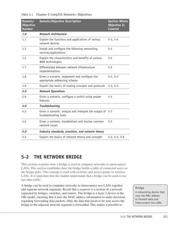
TABLE 5-1 Chapter 5 CompTIA Network+ Objectives
Domain/Objective Number
Domain/Objective Description Section Where Objective Is Covered
1.0 Network Architecture
1.1 Explain the functions and applications of various network devices
5-3, 5-4
1.3 Install and configure the following networking services/applications
5-4
1.4 Explain the characteristics and benefits of various WAN technologies
5-4
1.7 Differentiate between network infrastructure implementations
5-2
1.8 Given a scenario, implement and configure the appropriate addressing schema
5-2, 5-3
1.9 Explain the basics of routing concepts and protocols 5-3, 5-5
2.0 Network Operations
2.6 Given a scenario, configure a switch using proper features
5-4
4.0 Troubleshooting
4.2 Given a scenario, analyze and interpret the output of troubleshooting tools
5-3
4.6 Given a scenario, troubleshoot and resolve common network issues
5-5
5.0 Industry standards, practices, and network theory
5.2 Explain the basics of network theory and concepts 5-2, 5-4, 5-6
5-2 THE NETWORK BRIDGEThis section examines how a bridge is used in computer networks to interconnect
LANs. This section establishes how the bridge builds a table of connected users on
the bridge ports. This concept is used with switches and access points in wireless
LANs. It is important that the student understands that a bridge can be used to iso-
late data traffic.
A bridge can be used in computer networks to interconnect two LANs together
and separate network segments. Recall that a segment is a section of a network
separated by bridges, switches, and routers. The bridge is a layer 2 device in the
OSI model, meaning that it uses the MAC address information to make decisions
regarding forwarding data packets. Only the data that needs to be sent across the
bridge to the adjacent network segment is forwarded. This makes it possible to
BridgeA networking device that uses the MAC address to forward data and interconnect two LANs

222 CHAPTER 5: INTERCONNECTING THE LANS
isolate or segment the network data traffic. An example of using a bridge to seg-
ment two Ethernet LANs is shown in Figure 5-1. The picture shows that LAN
A connects to port 1 of the bridge and LAN B connects to port 2 on the bridge,
creating two segments, as shown. There are four computers in LAN A and three
computers in LAN B. It is important to note that bridges are now legacy network-
ing devices, but studying these will help you better understand the functionality of
switches, especially how data traffic is sent to connected LANs.
Bridges monitor all data traffic in each of the LAN segments connected to its ports.
Recall that a port is an input/output connection on a networking device. The bridges
use the MAC addresses to build a bridging table of MAC addresses and port loca-
tions for hosts connected to the bridge ports. A sample bridging table is provided in
Table 5-2. The table shows the stored MAC address and the port where the address
was obtained.
TABLE 5-2 Bridging Table
MAC Address Port
00-40-96-25-85-BB 1
00-40-96-25-8E-BC 1
00-60-97-61-78-5B 2
00-C0-4F-27-20-C7 2
The source MAC address is stored in the bridge table as soon as a host talks (trans-
mits a data packet) on the LAN. For example, if computer 1 in LAN A sends a
message to computer 2 (see Figure 5-1), the bridge will store the MAC addresses of
both computers and record that both of these computers are connected to port 1. If
computers 5 or 6 are placing data packets on the network, then the source MAC ad-
dresses for 5 and 6 are stored in the bridge table and it is recorded that these com-
puters connect to port 2 on the bridge. The MAC addresses for computers 3 and 4
will not be added to the bridging table until each transmits a data packet.
LAN A
Comp 1Comp 2Comp 3Comp 4
LAN B
Comp 5Comp 6Comp 7
Port 1 Port 2
Segment
Bridge
FIGURE 5-1 Using a bridge to interconnect two Ethernet LANs.
Bridging TableList of MAC addresses and port locations for hosts connected to the bridge ports

223 5-2: THE NETWORK BRIDGE
The bridge monitors the data on its ports to check for an association between the
destination MAC address of the Ethernet frames to any of the hosts connected to
its ports. An association indicates that the destination MAC address for a host is
connected to one of the ports on the bridge. If an association is found, the data is
forwarded to that port. For example, assume that computer 1 sends a message to
computer 5 (see Figure 5-1). The bridge detects an association between the desti-
nation MAC address for computer 5 and port 2. The bridge then forwards the data
from computer 1 to computer 5 in LAN B via port 2.
The capability of a bridge to forward data packets only when there is an association
is used to isolate data traffic in each segment. For example, assume that computer
1 and computer 2 in LAN A generate a lot of data traffic. The computers in LAN B
will not see any of the data traffic as long as there is not an association between the
destination MAC addresses of the Ethernet packets and any of the hosts in LAN B
(computers 5, 6, and 7).
A potential problem with bridges has to do with the way broadcasts are handled. A
broadcast means the message is being sent to all computers on the network; there-
fore, all broadcasts in a LAN will be forwarded to all hosts connected within the
bridged LANs. For example, the broadcast associated with an ARP will appear on
all hosts. ARP stands for Address Resolution Protocol, which is a protocol used to
map an IP address to its MAC address. In the address resolution protocol, a broad-
cast is sent to all hosts in a LAN connected to the bridge. This is graphically shown
in Figure 5-2. The bridge forwards all broadcasts; therefore, an ARP request broad-
casting the message “Who has this IP address?” is sent to all hosts on the LAN. The
data packets associated with ARP requests are small, but it requires computer time
to process each request. Excessive amounts of broadcasts being forwarded by the
bridge can lead to a broadcast storm, resulting in degraded network performance,
called a network slowdown.
The MAC address entries stored in a bridge table are temporary. Each MAC ad-
dress entry to the bridge table remains active as long as there is periodic data traffic
activity from that host on its port. However, an entry into the table is deleted if the
port becomes inactive. In other words, the entries stored into the table have a lim-
ited lifetime. An expiration timer will commence once the MAC address is entered
into the bridge table. The lifetime for the entry is renewed by new data traffic by the
computer, and the MAC address is reentered.
In a similar manner, all networking devices (for example, computers) contain an
ARP cache, a temporary storage of MAC addresses recently contacted. This is also
called the ARP table. The ARP cache holds the MAC address of a host, and this
enables the message to be sent directly to the destination MAC address without the
computer having to issue an ARP request for a MAC address. The following list
outlines typical steps of a communication process between computer 1 and com-
puter 2.
AssociationIndicates that the destination address is for a networking device connected to one of the ports on the bridge
BroadcastTransmission of the data to all connected devices
ARPAddress Resolution Protocol
Broadcast StormExcessive amounts of broadcasts
Network SlowdownDegraded network performance
ARP CacheTemporary storage of MAC addresses recently contacted
ARP TableAnother name for the ARP cache

224 CHAPTER 5: INTERCONNECTING THE LANS
PC PC PC
PC PC PC
PC
Hub
Hub
TransparentBridge
Data TrafficBroadcast Traffic
6
6
FIGURE 5-2 An example of using a bridge to isolate data traffic.
1. Computer 1 checks its ARP cache to determine if it already has the MAC ad-
dress of computer 2. If it does, it will skip to the final step; otherwise, it pro-
ceeds to the next step.
2. Computer 1 generates an ARP request message for computer 2 with its own
MAC and IP information included.
3. Computer 1 then broadcasts the ARP request message on its local network.
4. Every local network device processes the ARP request message. Those com-
puters that are not computer 2 will discard the message.
5. Only a match, which is computer 2, generates an ARP reply message and up-
dates its ARP cache with computer 1 MAC and IP information.
6. Computer 2 sends an ARP reply message directly to computer 1.
7. Computer 1 receives the ARP reply message and updates its ARP cache with
the MAC and IP of computer 2.

225 5-2: THE NETWORK BRIDGE
The ARP cache contents on a Windows computer can be viewed using the arp -a
command while in the command prompt, as shown here:
Windows Mac OS X
C:\arp –a jmac:~mymac$ arp –a
Interface: 10.10.20.2 on Interface x1000002 C1.salsa.org (192.168.12.1) at
Internet Address Physical Address Type 00-08-a3-a7-78-0c on en1
10.10.20.3 00-08-a3-a7-78-0c dynamic [ethernet]
10.10.20.4 00-03-ba-04-ba-ef dynamic C3.salsa.org (192.168.12.1) at
00-08-a3-a7-78-0c on en1
[ethernet]
The ARP cache contents on a Mac OS X computer can be viewed using the arp -a
command while in the terminal mode.
The following message is generated if all the ARP entries have expired:
c:\arp -a
No ARP Entries Found
The name for the type of bridge used to interconnect two LANs running the same
type of protocol (for example, Ethernet) is a transparent bridge. Bridges are also
used to interconnect two LANs that are operating two different networking proto-
cols. For example, LAN A could be an Ethernet LAN and LAN B could be a token
ring. This type of bridge is called a translation bridge. An example is provided in
Figure 5-3. The bridge allows data from one LAN to be transferred to another. Also
the MAC addressing information is standardized so the same address information is
used regardless of the protocol.
PC
PC
PC
Hub
PC
PC
PC
PC
Token ringEthernet
Token ringTranslationBridge6
FIGURE 5-3 Using a translation bridge to interconnect an Ethernet and token-ring LAN.
Transparent BridgeInterconnects two LANs running the same type of protocol
Translation BridgeUsed to interconnect two LANs that are operating two different networking protocols

226 CHAPTER 5: INTERCONNECTING THE LANS
A common application today using a bridge is interconnecting LANs using wireless
technology. The use of wireless bridges in LANs is a popular choice for intercon-
necting the LANs when the cost of physically connecting them is prohibitive. Wire-
less technology and its LAN applications were presented in Chapter 4, “Wireless
Networking.”
The use of a bridge is not as common as it used to be except for wireless network
applications. New networking technologies are available that provide similar capa-
bilities to the bridge but that are much more powerful. However, the bridge still is
useful and has several advantages. Table 5-3 provides a summary of the advantages
and disadvantages of a networking bridge.
TABLE 5-3 Summary of the Advantages and Disadvantages of a Bridge for Interconnecting LANs
Advantages Disadvantages
Easy to install Works best in low-traffic areas
Does an excellent job of isolating the data traffic in two segments
Forwards broadcasts and is susceptible to broadcast storms
Relatively inexpensive
Can be used to interconnect two LANs with different protocols and hardware
Reduces collision domains (remember how the CSMA/CD protocol works)
Section 5-2 Review
This section has covered the following Network+ Exam objectives.
1.7 Differentiate between network infrastructure implementations
This section presents a look at the network bridge. The advantages and dis-advantages of the network bridge are presented in Table 5-3. A key concept presented in this section is an “association” that indicates that the destination address for a networking device has been obtained.
1.8 Given a scenario, implement and configure the appropriate addressing
schema
Another important concept presented in this section is that a bridge will pass a broadcast to all devices connected to its ports. Excessive broadcast can poten-tially have a negative impact on data traffic and result in a network slowdown. The purpose of the bridging table for storing the MAC addresses of connected devices was also presented. Each MAC address entry to the bridge table remains active as long as there is periodic data traffic activity from that host on its port. However, an entry into the table is deleted if the port becomes inactive.

227 5-2: THE NETWORK BRIDGE
5.2 Explain the basics of network theory and concepts
An important concept presented in this section is that a bridge will pass a broad-cast to all devices connected to its ports. Excessive broadcast can potentially have a negative impact on data traffic and result in a network slowdown.
Test Your Knowledge 1. Which command is used on a computer to view the contents of the ARP
cache?
a. arp -c
b. arp -l
c. arp -a
d. arp -b
e. arp
2. An association indicates which of the following?
a. That the destination address for a networking device is connected to
one of its ports
b. That the source address is for a networking device connected to one
of the ports on the bridge
c. That the destination address is for a networking device connected to
one of the ports on the hub
d. That the source address is for a networking device connected to one
of the ports on the hub
3. An ARP cache is which of the following?
a. A temporary storage of IP addresses for networking devices recently
contacted
b. A temporary storage of MAC addresses for networking devices to be
contacted
c. A temporary storage of IP addresses for networking devices to be
contacted
d. A temporary storage of MAC addresses for networking devices re-
cently contacted

228 CHAPTER 5: INTERCONNECTING THE LANS
5-3 THE NETWORK SWITCHThe network switch provides a method for isolating collision domains for inter-
connected LANs. In fact, most new networks should be using a layer 2 switch
rather than a hub. Make sure the student understands why this is called a layer 2
switch (MAC address). This section contains a Hub-Switch comparison that shows
how the switch isolates data traffic. Use this comparison to show the student the
improvement with the switch using the a network analyzer such as Wireshark.
You might want to have the students try to duplicate this task in lab. The section
concludes with an overview of a managed switch. Switches vary for make and
manufacturer, but the basic concepts are the same. The use of the Cisco Network
Assistant (CNA) software for managing switches is presented. The two modes used
in a switch to forward frames (store-and-forward and cut-through) are presented.
The student should be familiar with this and any related concepts.
The bridge provides a method for isolating the collision domains for interconnected
LANs but lacks the capability to provide a direct data connection for the hosts. The
bridge forwards the data traffic to all computers connected to its port. This was
shown in Figure 5-2. The networking hub provides a technology for sharing ac-
cess to the network with all computers connected to its ports in the LAN but lacks
the capability to isolate the data traffic and provide a direct data connection from
the source to the destination computer. The increase in the number of computers
being used in LANs and the increased data traffic are making bridges and hubs of
limited use in larger LANs. Basically, there is too much data traffic to be shared
by the entire network. What is needed is a networking device that provides a direct
data connection between communicating devices. Neither the bridge nor the hub
provides a direct data connection for the hosts. A technology developed to improve
the efficiency of the data networks and address the need for direct data connections
is the layer 2 switch.
The layer 2 switch is an improved network technology that addresses the issue of
providing direct data connections, minimizing data collisions, and maximizing
the use of a LAN’s bandwidth; in other words, that improves the efficiency of the
data transfer in the network. The switch operates at layer 2 of the OSI model and
therefore uses the MAC or Ethernet address for making decisions for forwarding
data packets. The switch monitors data traffic on its ports and collects MAC address
information in the same way the bridge does to build a table of MAC addresses for
the devices connected to its ports. The switch has multiple ports similar to the hub
and can switch in a data connection from any port to any other port, similar to the
bridge. This is why the switch is sometimes called a multiport bridge. The switch
minimizes traffic congestion and isolates data traffic in the LAN. Figure 5-4 pro-
vides an example of a switch being used in a LAN.
Layer 2 SwitchAn improved network technology that provides a direct data connection for network devices in a LAN
Multiport BridgeAnother name for a layer 2 switch

229 5-3: THE NETWORK SWITCH
Figure 5-4 shows a switch being used in the LAN to interconnect the hosts. In this
figure, the hub has been replaced with a switch. The change from a hub to a switch
is relatively easy. The port connections are the same (RJ-45), and once the con-
nections are changed and the device is powered on, the switch begins to make the
direct data connections for multiple ports using layer 2 switching.
Printer
Switch
Switch
Server 1
2
1
3
LAN A
FIGURE 5-4 A switch used to interconnect hosts in a LAN.
The LAN shown in Figure 5-5 contains 14 computers and 2 printers connected to
16 ports on the switch, configured in a star topology. If the computer connected to
port 1 is printing a file on the laser printer (port 12), the switch will set up a direct
connection between ports 1 and 12. The computer at port 14 could also be commu-
nicating with the computer at port 7, and the computer at port 6 could be printing
a file on the color printer at port 16. The use of the switch enables simultaneous
direct data connections for multiple pairs of hosts connected to the network. Each
switch connection provides a link with minimal collisions and therefore maximum
use of the LAN’s bandwidth. A link with minimal collisions is possible because
only the two computers that established the link will be communicating over the
channel. Recall that in the star topology each host has a direct connection to the
switch. Therefore, when the link is established between the two hosts, their link is
isolated from any other data traffic. However, the exception to this is when broad-
cast or multicast messages are sent in the LAN. In the case of a broadcast message,
the message is sent to all devices connected to the LAN. A multicast message is
sent to a specific group of hosts on the network.
MulticastMessages are sent to a specific group of hosts on the network

230 CHAPTER 5: INTERCONNECTING THE LANS
1
Laser Printer
Color Printer
2
3
4
5
6
7
8
9
10
11
13
14
15
Switch
FIGURE 5-5 A switch used to interconnect the networking devices in a LAN.
Hub–Switch ComparisonAn experiment was set up to test the data handling characteristics of a hub and a
switch given the same input instructions. The objective of this experiment was to
show that data traffic is isolated with a switch but not with a hub. For this experi-
ment, a LAN using a hub and a LAN using a switch were assembled. The LANs are
shown in Figure 5-6(a) and (b). Each LAN contains four computers connected in
a star topology. The computers are marked 1–4 for reference. The IP addresses are
listed for each host.

231 5-3: THE NETWORK SWITCH
Hub
Computer 410.10.10.4
Computer 310.10.10.3
Computer 210.10.10.2
Computer 110.10.10.1(a)
Computer 210.10.10.2
Computer 110.10.10.1(b)
Switch
Computer 410.10.10.4
Computer 310.10.10.3
6
FIGURE 5-6 (a) The LAN experiment with a hub; (b) the LAN experiment with a switch.
The Hub Experimental ResultsIn this experiment, computer 1 pinged computer 3. Computer 2 was used to capture
the LAN data traffic using a network protocol analyzer. What are the expected re-
sults? Remember, a hub is a multiport repeater, and all data traffic input to the hub
is passed on to all hosts connected to its ports. See the Ping Command Review sec-
tion that follows for a brief review of the use of the ping command.
Ping Command ReviewThe ping command is used to verify that a network connection exists between two
computers. The command format for ping is:
ping [ip address] {for this example ping 10.10.10.3}
After a link is established between the two computers, a series of echo requests and
echo replies are issued by the networking devices to test the time it takes for data to
pass through the link. The protocol used by the ping command is the Internet Con-
nection Message Protocol (ICMP).
The ping command is issued to an IP address; however, delivery of this command
to the computer designated by the IP address requires that a MAC address be iden-
tified for final delivery. The computer issuing the ping might not know the MAC
address of the computer holding the identified IP address (no entry in the ARP
cache table); therefore, an ARP request is issued. An ARP request is broadcast to
all computers connected in the LAN. The computer that holds the IP address replies
with its MAC address, and a direct line of communications is then established.

232 CHAPTER 5: INTERCONNECTING THE LANS
The data traffic collected by computer 2 when computer 1 pinged computer 3 is pro-
vided in Figure 5-7. The first line of the captured data shows the ARP request ask-
ing who has the IP address 10.10.10.3. The second line of the captured data shows
the reply from 10.10.10.3 with the MAC address of 00-B0-D0-25-BF-48. The next
eight lines in the captured data are the series of four echo requests and replies asso-
ciated with a ping request. Even though computer 2 was not being pinged or reply-
ing to the ARP request, the data traffic was still present on computer 2’s hub port.
The echo reply is from a Dell network interface card with the last six characters of
the MAC address of 25-BF-48. The echo request is coming from a computer with
13-99-2E as the last six hex characters of its MAC address.
FIGURE 5-7 The captured data traffic by computer 2 for the LAN [Figure 5-6(a)] using a hub.
The Switch Experimental ResultsThe same experiment was repeated for the LAN shown in Figure 5-6(b), this time
using a switch to interconnect the computers instead of a hub. This network con-
sists of four computers connected in a star topology using a switch at the center of
the network. The ping command was sent from computer 1 to computer 3, ping 10.10.10.3. The ARP cache for computer 1 is empty; therefore, the MAC address
for computer 3 is not known by computer 1. An ARP request is issued by computer
1, and computer 3 replies. The series of echo requests and echo replies follow; how-
ever, the data traffic captured by computer 2 (Figure 5-8), shows the ARP request
asking who has the IP address 10.10.10.3. This is the last of the data communica-
tions between computers 1 and 3 seen by computer 2. A direct line of communica-
tion between computers 1 and 3 is established by the switch that prevents computer
2 from seeing the data traffic from computers 1 and 3. The only data traffic seen by
computer 2 in this process was the broadcast of the ARP request. This is true for
any other hosts in the LAN. The results of this experiment show that the use of the
switch substantially reduces data traffic in the LAN, particularly unnecessary data
traffic. The experiment shows that the broadcast associated with an ARP request
is seen by all computers but not the ARP replies in a LAN using a switch. This is
because a direct data connection is established between the two hosts. This experi-
ment used pings and ARPs; however, this same advantage of using a switch is true
when transferring files, image downloads, file printing, and so on. The data traffic
is isolated from other computers on the LAN. Remember, the switch uses MAC

233 5-3: THE NETWORK SWITCH
addresses to establish which computers are connected to its ports. The switch then
extracts the destination MAC address from the Ethernet data packets to determine
to which port to switch the data.
FIGURE 5-8 The data traffic captured by computer 2 for the LAN [Figure 5-6(b)] using a switch.
Managed SwitchesA managed switch is simply a network switch that allows the network administrator
to monitor, configure, and manage certain network features such as which comput-
ers are allowed to access the LAN via the switch. Access to the management features
for the switch is password protected so that only the network administrators can gain
entry. The following information describes some of the features of the managed in-
terface for a Cisco Catalyst 2900 series switch established using the Cisco Network Assistant (CNA). This software can be downloaded from Cisco and provides an easy
way to manage the features of the Cisco switches. (Note: The download requires that
you have set up a Cisco user account and password. The Cisco Network Assistant
provides for a centralized mode for completing various network administration tasks
for switches, routers, and wireless networking equipment.)
The start-up menu for a Cisco Catalyst 2960 switch obtained via the CNA is pro-
vided in Figure 5-9. The image is showing the current setup for the switch. The
assigned IP address for the switch is 192.168.1.1, and a router and a switch are in-
terconnected with the switch. The steps for setting the IP address for an interface on
the switch are presented later in this section.
FIGURE 5-9 The start-up menu of a Cisco Catalyst switch using the Cisco Network Administrator software.
Managed SwitchAllows the network administrator to monitor, configure, and manage select network features
Cisco Network Assistant (CNA)A management software tool from Cisco that simplifies switch configuration and troubleshooting

234 CHAPTER 5: INTERCONNECTING THE LANS
The current connections to the ports on the switch can be viewed by clicking the
stacked switch icon at the top of the screen as shown in Figure 5-10. The image
of the switch port connections shows ports 1, 2, and 3 are brighter, indicating that
there are networking devices connected to the ports. The MAC addresses of the de-
vices connected to the switch ports can be displayed by clicking the MAC address
button under the Configure button as shown in Figure 5-11. Four MAC addresses
are assigned to port 1, one MAC address is assigned to port 2, and one MAC ad-
dress is assigned to port 3. Multiple networking devices can be connected to a port
if the devices are first connected to another switch or hub and the output of the
switch or hub is connected to one switch port. An example showing four devices
connected through a hub to port 1 on the switch is shown in Figure 5-12. The out-
put interface information for the MAC Addresses table shows the following infor-
mation in Figure 5-11:
FastEthernet 0/1
FastEthernet 0/2
FastEthernet 0/3
Notice that the Dynamic Address tab is highlighted. This indicates that this is a
listing of the MAC addresses that have been assigned dynamically. Dynamic as-signment means that the MAC address was assigned to a port when a host was
connected. There is also a tab for Static Addresses. Static addressing indicates that
the MAC address has been manually assigned to an interface, and the port assign-
ment does not expire. The Secure tab shows what switch ports have been secured. A
secure address means that a MAC address has been assigned to a port, and the port
will automatically disable itself if a device with a different MAC address connects
to the secured port.
Stacked Switch Icon
FIGURE 5-10 The highlighted ports showing the current connections and the location of the stacked switches icon.
The FastEthernet 0/1, FastEthernet 0/2, FastEthernet 0/3 notation indicates the
[Interface Type Slot#/Interface#] on the switch, and FastEthernet indicates that this
interface supports 100Mbps and 10Mbps data rate connections.
The “Aging Time” is listed to be 300 seconds. Aging time is the length of time a
MAC address remains assigned to a port. The assignment of the MAC address will
be removed if there is no data activity within this time. If the computer with the as-
signed MAC address initiates new data activity, the aging time counter is restarted,
and the MAC address remains assigned to the port. The management window
Dynamic AssignmentMAC addresses are assigned to a port when a host is connected
Static AddressingThe MAC address has been manually assigned to a switch port
Secure AddressThe switch port will automatically disable itself if a device with a different MAC address connects to the port
Aging TimeThe length of time a MAC address remains assigned to a port

235 5-3: THE NETWORK SWITCH
shows a switch setting for enabling “Aging.” This switch is used to turn off the ag-
ing counter so that a MAC address assignment on a port never expires.
FIGURE 5-11 The menu listing the MAC addresses currently connected to the switch.
Hub
MAC address:0040 9625 85B3
0040 9625 8EBC
0060 9761 7A5B
00C0 4F27 20C7
Switch6
1
2
3
4
FIGURE 5-12 An example of a hub connected to a switch port, with four computers connected to the hub.

236 CHAPTER 5: INTERCONNECTING THE LANS
The IP address on a switch interface can be configured using the Cisco Network
Assistant software by clicking Configure > Device Properties > IP Addresses.
This opens the IP Addresses menu shown in Figure 5-13. Click the area where the
IP address should be entered. This opens a text box for entering the IP address. En-
ter the IP address and click OK to save the IP address.
FIGURE 5-13 Configuring an IP address on an interface.
The benefits of using a network switch are many in a modern computer network.
These benefits include less network congestion, faster data transfers, and excellent
manageability. It has been shown that a network switch can be used to replace the
network hub, and the advantage is that data traffic within a LAN is isolated. The
term for this is isolating the collision domains, which is breaking the network into
segments. A segment is a portion of the network where the data traffic from one
part of the network is isolated from the other networking devices. A direct benefit
of isolating collision domains is that there will be an increase in the data transfer
speed and throughput. This is due to the fact that the LAN bandwidth is not being
shared and chances of data collisions are minimized. As a result, the LAN will ex-
hibit faster data transfers and latency within the LAN will be significantly reduced.
Reduced latency means that the data packets will arrive at the destination more
quickly.
Switches learn the MAC addresses of the connected networking by extracting the
MAC address information from the headers of Ethernet data packet headers of
transmitted data packets. The switch will map the extracted MAC address to the
port where the data packet came in. This information is stored in Content Address-able Memory (CAM). CAM is a table of MAC address and port mapping used by
the switch to identify connected networking devices. The extracted MAC addresses
are then used by the switch to map a direct communication between two network
devices connected to its ports. The MAC address and port information remain in
CAM as long as the device connected to the switch port remains active. A time-
stamp establishes the time when the mapping of the MAC address to a switch port
Isolating the Collision DomainsBreaking the network into segments where a segment is a portion of the network where the data traffic from one part of the network is isolated from the other networking devices
Content Addressable Memory (CAM)A table of MAC addresses and port mapping used by the switch to identify connected networking devices

237 5-3: THE NETWORK SWITCH
is established. However, switches limit the amount of time address and port infor-
mation are stored in CAM. This is called aging time. The mapping information will
be deleted from the switch’s CAM if there is no activity during this set time. This
technique keeps the mapping information stored in CAM up-to-date.
What happens if the destination MAC address is not stored in CAM? In this case,
the packet is transmitted out all switch ports except for the port where the packet
was received. This is called flooding.
It has been shown that switches minimize the collision domain due to the fact
that a direct switch connection is made between networking devices. However, it
is important to remember that switches do not reduce the broadcast domain. In a
broadcast domain, any network broadcast sent over the network will be seen by all
networking devices in the same network. Broadcasts within a LAN will be passed
by switches. Refer to the discussion of Figure 5-7 and 5-8 for an example.
Two modes used in a switch to forward frames: store-and-forward and cut-through.
• Store-and-Forward: In this mode, the entire frame of data is received before
any decision is made regarding forwarding the data packet to its destination.
There is switch latency in this mode because the destination and source MAC
addresses must be extracted from the packet, and the entire packet must be re-
ceived before it is sent to the destination. The term switch latency is the length
of time a data packet takes from the time it enters a switch until it exits. An ad-
vantage of the store-and-forward mode is that the switch checks the data packet
for errors before it is sent on to the destination. A disadvantage is lengthy data
packets will take a longer time before they exit the switch and are sent to the
destination.
• Cut-Through: In this mode, the data packet is forwarded to the destination as
soon as the destination MAC address has been read. This minimizes the switch
latency; however, no error detection is provided by the switch. There are two
forms of cut-through switching—Fast-Forward and Fragment Free.
• Fast-Forward: This mode offers the minimum switch latency. The re-
ceived data packet is sent to the destination as soon as the destination
MAC address is extracted.
• Fragment-Free: In this mode, fragment collisions are filtered out by
the switch. Fragment-collisions are collisions that occur within the first
64 bytes of the data packet. Recall from Chapter 1, “Introduction to
Computer Networks,” Table 1-1 that the minimum Ethernet data packet
size is 64 bytes. The collisions create packets smaller than 64 bytes,
which are discarded. Latency is measured from the time the first bit is
received until it is transmitted .
• Adaptive Cut-Through: This is a combination of the store-and-forward
mode and cut-through. The cut-through mode is used until an error threshold
(errors in the data packets) has been exceeded. The switch mode changes
from cut-through to store-and-forward after the error threshold has been
exceeded.
FloodingThe term used to describe what happens when a switch doesn’t have the destination MAC address stored in CAM
Broadcast DomainAny network broadcast sent over the network will be seen by all networking devices in this domain.
Store-and-ForwardThe entire frame of data is received before any decision is made regarding forwarding the data packet to its destination.
Cut-ThroughThe data packet is forwarded to the destination as soon as the destination MAC address has been read.
Switch LatencyThe length of time a data packet takes from the time it enters a switch until it exits
Error ThresholdThe point where the number of errors in the data packets has reached a threshold and the switch changes from the cut-through to the store-and-forward mode

238 CHAPTER 5: INTERCONNECTING THE LANS
Multilayer SwitchesNewer switch technologies are available to help further improve the performance of
computer networks. The term used to describe these switches is multilayer switches (MLS). An example is a layer 3 switch. Layer 3 switches still work at layer 2 but
additionally work at the network layer (layer 3) of the OSI model and use IP ad-
dressing for making decisions to route a data packet in the best direction. The major
difference is that the packet switching in basic routers is handled by a programmed
microprocessor. The layer 3 switch uses application-specific integrated circuits
(ASICs) hardware to handle the packet switching. The advantage of using hardware
to handle the packet switching is a significant reduction in processing time (soft-
ware versus hardware). In fact, the processing time of layer 3 switches can be as
fast as the input data rate. This is called wire speed routing, where the data packets
are processed as fast as they are arriving. Multilayer switches can also work at the
upper layers of the OSI model. An example is a layer 4 switch that processes data
packets at the transport layer of the OSI model.
Multilayer Switch (MLS)Operates at layer 2 but functions at the higher layers
Wire Speed RoutingData packets are processed as quickly as they arrive.
Section 5-3 Review
This section has covered the following Network+ Exam objectives.
1.1 Explain the functions and applications of various network devices
This section introduced the use of the network switch. A discussion on a man-aged switch was presented incorporating the use of the Cisco Network Assistant. Examples of dynamic MAC address assignment and aging time were also presented.
1.8 Given a scenario, implement and configure the appropriate addressing
schema
The concept of multicast messaging where messages are sent to a specific group of hosts on the network was presented in this section.
1.9 Explain the basics of routing concepts and protocols
This section presented a look at latency. A direct benefit of isolating collision do-mains is that there will be an increase in the data transfer speed and throughput. Reduced latency means that the data packets will arrive at the destination more quickly.
4.2 Given a scenario, analyze and interpret the output of troubleshooting
tools
The use of the ping command was demonstrated in this section. This is a very important troubleshooting tool.

239 5-4: THE ROUTER
5-4 THE ROUTERThe concept of the use of a router in a computer network is introduced in this sec-
tion. Router configuration is not introduced until Chapter 6, “TCP/IP,” but this sec-
tion introduces the basic hardware and interfaces available with the router.
The router is the most powerful networking device used today to interconnect
LANs. The router is a layer 3 device in the OSI model, which means the router
uses the network address (layer 3 addressing) to make routing decisions regard-
ing forwarding data packets. Remember from Chapter 1, section 3, that the OSI
model separates network responsibilities into different layers. In the OSI model, the
layer 3 or network layer responsibilities include handling of the network address.
The network address is also called a logical address, rather than being a physical
address such as the MAC address. The physical address is the hardware or MAC
address embedded into the network interface card. The logical address describes
the IP address location of the network and the address location of the host in the
network.
Network AddressAnother name for the layer 3 address
Logical AddressDescribes the IP address location of the network and the address location of the host in the network
Test Your Knowledge 1. A layer 2 switch does which of the following? (Select all that apply.)
a. Provides a direct connection for networking devices in a LAN
b. Uses MAC addressing from the Data Link Layer
c. Uses MAC addressing from the Network Layer
d. Uses IP addressing from the Network Layer
2. The network administrator wants to verify the network connection at
10.10.20.5. Which of the following commands can be used to verify the
connection? (Select all that apply.)
a. ping all 10.10.20.5
b. ping 10.10.20.5
c. ping -t 10.10.20.5
d. ping -2 10.10.20.5
3. A managed switch allows the network administrator to do what? (Select all
that apply.)
a. Monitor network features.
b. Configure network features.
c. Manage certain network features.
d. All of these answers are correct.
e. None of these answers is correct.
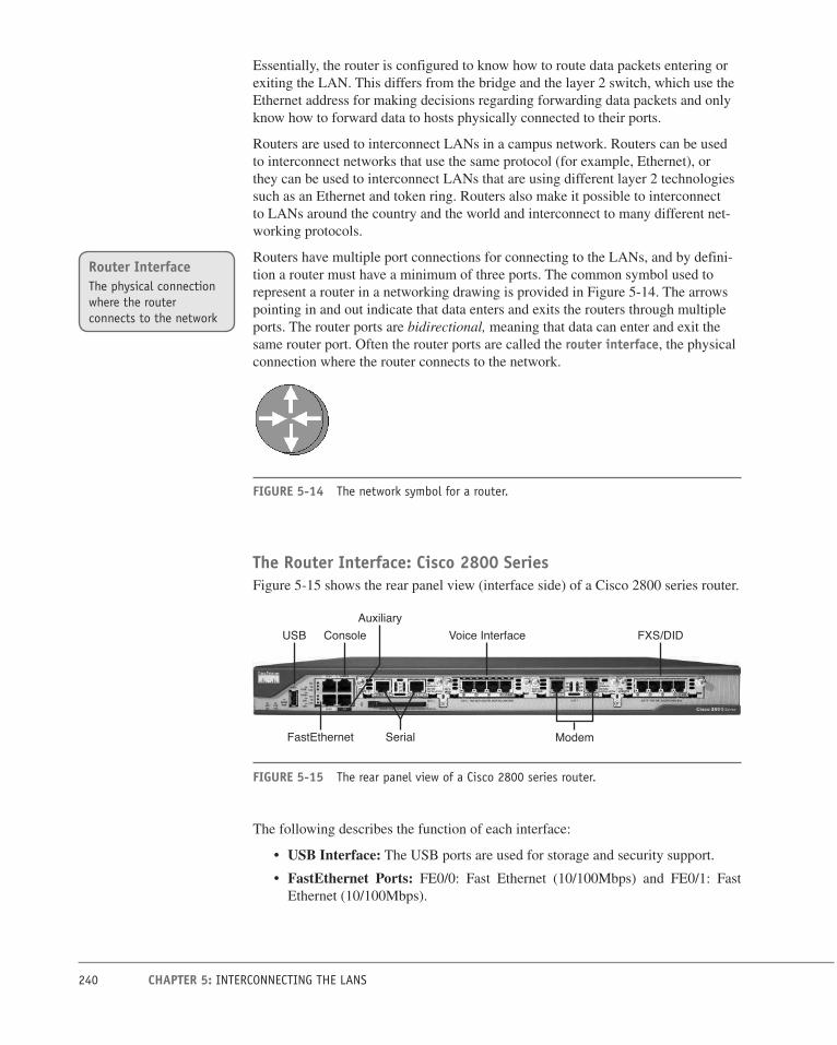
240 CHAPTER 5: INTERCONNECTING THE LANS
Essentially, the router is configured to know how to route data packets entering or
exiting the LAN. This differs from the bridge and the layer 2 switch, which use the
Ethernet address for making decisions regarding forwarding data packets and only
know how to forward data to hosts physically connected to their ports.
Routers are used to interconnect LANs in a campus network. Routers can be used
to interconnect networks that use the same protocol (for example, Ethernet), or
they can be used to interconnect LANs that are using different layer 2 technologies
such as an Ethernet and token ring. Routers also make it possible to interconnect
to LANs around the country and the world and interconnect to many different net-
working protocols.
Routers have multiple port connections for connecting to the LANs, and by defini-
tion a router must have a minimum of three ports. The common symbol used to
represent a router in a networking drawing is provided in Figure 5-14. The arrows
pointing in and out indicate that data enters and exits the routers through multiple
ports. The router ports are bidirectional, meaning that data can enter and exit the
same router port. Often the router ports are called the router interface, the physical
connection where the router connects to the network.
FIGURE 5-14 The network symbol for a router.
The Router Interface: Cisco 2800 SeriesFigure 5-15 shows the rear panel view (interface side) of a Cisco 2800 series router.
ModemFastEthernet
USB Console Voice Interface FXS/DIDAuxiliary
Serial
FIGURE 5-15 The rear panel view of a Cisco 2800 series router.
The following describes the function of each interface:
• USB Interface: The USB ports are used for storage and security support.
• FastEthernet Ports: FE0/0: Fast Ethernet (10/100Mbps) and FE0/1: Fast
Ethernet (10/100Mbps).
Router InterfaceThe physical connection where the router connects to the network

241 5-4: THE ROUTER
• Console Input: This input provides an RS-232 serial communications link
into the router for initial router configuration. A special cable, called a console cable, is used to connect the console input to the serial port on a computer.
The console cable can have RJ-45 plugs on each end and requires the use of an
RJ-45 to DB9 adapter for connecting to the computer’s COM1 or COM2 serial
port. The console cable can also have an RJ-45 connector on one end and an
integrated DB9 connector on the other end.
• Auxiliary Input: This input is used to connect a dial-in modem into the router.
The auxiliary port provides an alternative way to remotely log in to the router
if the network is down. This port also uses an RJ-45 connection.
• Serial Interface: CTRLR T1 1 and CTRLR T1 0.
This is a serial connection, and it has a built-in CSU/DSU. This interface is used
to provide a T1 connection to the communications carrier. (Note: The CSU/DSU
function is presented in Chapter 8, “Introduction to Switch Configuration.”)
This type of connection (RJ-45) replaces the older cabling using V.35 cable
(shown later in Figure 5-18). There are three LEDs on this interface:
• AL—alarm
• LP—loop
• CD—Carrier Detect
• Voice Interface Card (VIC2-4FXO): This interface shows four phone line con-
nections. This router can be programmed as a small Private Branch Exchange
(PBX) for use in a small office. The PBX function is presented in Chapter 10,
“Internet Technologies: Out to the Internet.”
• WAN Interface Card (WIC2AM): This interface has two RJ-11 jacks and two
V.90 analog internal modems. These modems can be used to handle both incom-
ing and outgoing modem calls. This interface is listed as modem in Figure 5-15.
• VIC-4FXS/DID: This interface is a four-port FXS and DID voice/fax inter-
face card. FXS is a Foreign Exchange Interface that connects directly to a
standard telephone. DID is Direct Inward Dialing and is a feature that enables
callers to directly call an extension on a PBX. This interface is listed as FXS/
DID in Figure 5-15.
The Router Interface—Cisco 2600 SeriesFigure 5-16 shows the rear panel view (interface side) of a Cisco 2600 series router.
Console
16-port Analog Modem DSU PowerSerial
Ethernet Auxiliary
FIGURE 5-16 The rear panel view of a Cisco 2600 series router.

242 CHAPTER 5: INTERCONNECTING THE LANS
The following describes the function of each interface to the network:
• Power On/Off: Turns on/off electrical power to the router.
• Auxiliary Input: Used to connect a dial-in modem into the router. The aux-
iliary port provides an alternative way to remotely log in to the router if the
network is down. This port also uses an RJ-45 connection.
• Console Input: Provides an RS-232 serial communications link into the router
for initial router configuration. A special cable, called a console cable, is used
to connect the console input to the serial port on a computer. The console cable
uses RJ-45 plugs on each end and requires the use of an RJ-45 to DB9 adapter
for connecting to the COM1 or COM2 serial port.
• Serial Ports: Provides a serial data communication link into and out of the
router, using V.35 serial interface cables.
• DSU Port: This T1 controller port connection is used to make the serial con-
nection to Telco. This module has a built-in CSU/DSU module. There are five
LEDs next to the RJ-45 jack. These LEDs are for the following:
• TD—Transmit Data
• P—Loop
• D—Receive Data
• D—Carrier Detect
• L—Alarm
• Ethernet Port: This connection provides a 10/100Mbps Ethernet data link.
• Analog Modem Ports: This router has a 16-port analog network module.
A media converter is used to convert the 15-pin AUI port to the 8-pin RJ-45 con-
nector. Figure 5-17 shows an example of an AUI to RJ-45 media converter. Media
converters are commonly used in computer networks to adapt layer 1 or physical
layer technologies from one technology to another. For example:
AUI to twisted pair (RJ-45) AUI to fiber
RJ-45 to fiber
Figure 5-18 shows a Cisco 7200 series router, which provides adaptable interfaces
for connecting to many physical layer technologies such as FastEthernet, gigabit
Ethernet, ATM, and FDDI.
Media ConverterUsed to adapt a layer 1 (physical layer) technology to another layer 1 technology

243 5-4: THE ROUTER
FIGURE 5-17 A CentreCom 210TS AUI to RJ-45 media converter.
FIGURE 5-18 A Cisco 7200 series router (courtesy of Cisco Systems).

244 CHAPTER 5: INTERCONNECTING THE LANS
Section 5-4 Review
This section has covered the following Network+ Exam objectives.
1.1 Explain the functions and applications of various network devices
The network router, a layer 3 device, was presented in this section. The network router is the most powerful networking device used today to interconnect LANs.
1.4 Explain the characteristics and benefits of various WAN technologies
The ATM interface for a network router was presented.
5.2 Explain the basics of network theory and concepts
This section has introduced the carrier detect/sense feature on a router. This fea-ture was present for both Cisco 2800 and 2600 series routers.
Test Your Knowledge 1. A router uses which of the following to make routing decisions regarding
forwarding data packets?
a. Router address
b. Network address
c. Fast link pulse
d. None of these answers is correct.
2. A logical address is which of the following?
a. MAC address
b. Router interface address
c. Network address
d. The ARP address
3. The physical connection where the router connects to the network is called
which of the following?
a. Console input
b. Auxiliary input
c. Router interface
d. USB interface
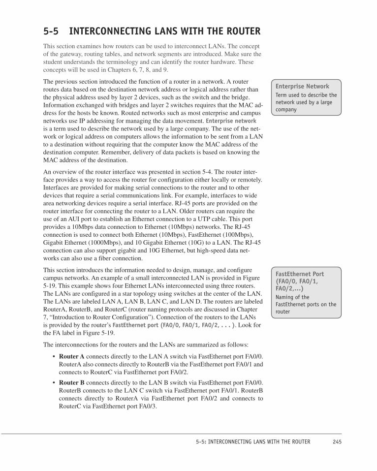
245 5-5: INTERCONNECTING LANS WITH THE ROUTER
5-5 INTERCONNECTING LANS WITH THE ROUTERThis section examines how routers can be used to interconnect LANs. The concept
of the gateway, routing tables, and network segments are introduced. Make sure the
student understands the terminology and can identify the router hardware. These
concepts will be used in Chapters 6, 7, 8, and 9.
The previous section introduced the function of a router in a network. A router
routes data based on the destination network address or logical address rather than
the physical address used by layer 2 devices, such as the switch and the bridge.
Information exchanged with bridges and layer 2 switches requires that the MAC ad-
dress for the hosts be known. Routed networks such as most enterprise and campus
networks use IP addressing for managing the data movement. Enterprise network
is a term used to describe the network used by a large company. The use of the net-
work or logical address on computers allows the information to be sent from a LAN
to a destination without requiring that the computer know the MAC address of the
destination computer. Remember, delivery of data packets is based on knowing the
MAC address of the destination.
An overview of the router interface was presented in section 5-4. The router inter-
face provides a way to access the router for configuration either locally or remotely.
Interfaces are provided for making serial connections to the router and to other
devices that require a serial communications link. For example, interfaces to wide
area networking devices require a serial interface. RJ-45 ports are provided on the
router interface for connecting the router to a LAN. Older routers can require the
use of an AUI port to establish an Ethernet connection to a UTP cable. This port
provides a 10Mbps data connection to Ethernet (10Mbps) networks. The RJ-45
connection is used to connect both Ethernet (10Mbps), FastEthernet (100Mbps),
Gigabit Ethernet (1000Mbps), and 10 Gigabit Ethernet (10G) to a LAN. The RJ-45
connection can also support gigabit and 10G Ethernet, but high-speed data net-
works can also use a fiber connection.
This section introduces the information needed to design, manage, and configure
campus networks. An example of a small interconnected LAN is provided in Figure
5-19. This example shows four Ethernet LANs interconnected using three routers.
The LANs are configured in a star topology using switches at the center of the LAN.
The LANs are labeled LAN A, LAN B, LAN C, and LAN D. The routers are labeled
RouterA, RouterB, and RouterC (router naming protocols are discussed in Chapter
7, “Introduction to Router Configuration”). Connection of the routers to the LANs
is provided by the router’s FastEthernet port (FA0/0, FA0/1, FA0/2, . . . ). Look for
the FA label in Figure 5-19.
The interconnections for the routers and the LANs are summarized as follows:
• Router A connects directly to the LAN A switch via FastEthernet port FA0/0.
RouterA also connects directly to RouterB via the FastEthernet port FA0/1 and
connects to RouterC via FastEthernet port FA0/2.
• Router B connects directly to the LAN B switch via FastEthernet port FA0/0.
RouterB connects to the LAN C switch via FastEthernet port FA0/1. RouterB
connects directly to RouterA via FastEthernet port FA0/2 and connects to
RouterC via FastEthernet port FA0/3.
Enterprise NetworkTerm used to describe the network used by a large company
FastEthernet Port (FA0/0, FA0/1, FA0/2,…)Naming of the FastEthernet ports on the router

246 CHAPTER 5: INTERCONNECTING THE LANS
• Router C connects directly to the LAN D switch via the FastEthernet port
FA0/0. Connection to RouterB is provided via Ethernet port FA0/1. RouterC
connects to RouterA via FastEthernet port FA0/2.
10.10.100.0 Net
10.10.200.0 Net 10.10.150.0 Net
segment
segment segment
Router B Router CRouter AFA0/2
FA0/2
FA0/0 FA0/0
FA0/2
FA0/1
FA0/1 FA0/0
LAN DLAN C
Switch SwitchSwitchSwitch
LAN A Server
Router A Port Addresses (LAN A)
LAN A Computers
FastEthernet 0/0 10.10.20.250 (Gateway Address)FastEthernet 0/1 10.10.200.1FastEthernet 0/2 10.10.100.1
Computer A1 10.10.20.1Computer A2 10.10.20.2
Subnet Mask 255.255.255.0
Router B Port Addresses (LAN B)
LAN B Computers
FastEthernet 0/0 10.10.10.250 (Gateway Address)FastEthernet 0/2 10.10.200.2FastEthernet 0/3 10.10.150.1
Computer A1 10.10.10.1Computer A2 10.10.10.2
Subnet Mask 255.255.255.0
Router B Port Addresses (LAN C)
LAN C Computers
FastEthernet 0/1 10.10.1.250 (Gateway Address)FastEthernet 0/2 10.10.200.2FastEthernet 0/3 10.10.150.1
Computer A1 10.10.1.1Computer A2 10.10.1.2
Subnet Mask 255.255.255.0
Router Port Addresses (LAN D)
LAN D Computers
FastEthernet 0/0 10.10.5.250 (Gateway Address)FastEthernet 0/1 10.10.150.2FastEthernet 0/2 10.10.100.2
Computer A1 10.10.5.1Computer A2 10.10.5.2
Subnet Mask 255.255.255.0
LAN C Server
10.10.1.0 Net 10.10.5.0 Net10.10.10.0 Net10.10.20.0 Net
LAN BLAN A
FA0/1FA0/3
A2 C2A1 B1 B2 C1 D1 D2
FIGURE 5-19 A small interconnected LAN.
The serial ports (S0/0, S0/1, S0/2,…) are not being used to interconnect the
routers in this sample campus network. The serial interfaces are typically used to
interconnect LANs that connect through a data communications carrier such as a
telephone company (Telco).
The network configuration provided in Figure 5-19 enables data packets to be sent
and received from any host on the network after the routers in the network have
been properly configured. For example, computer A1 in LAN A could be sending
data to computer D1 in LAN D. This requires that the IP address for computer D1
is known by the user sending the data from computer A1. The data from computer
A1 will first travel to the switch where the data is passed to RouterA via the FA0/0
FastEthernet data port. RouterA will examine the network address of the data
packet and use configured routing instructions stored in routing tables to decide
where to forward the data. RouterA determines that an available path to RouterC
is via the FA0/2 FastEthernet port connection. The data is then sent directly to
RouterC. RouterC determines that the data packet should be forwarded to the FA0/0
port to reach computer D1 in LAN D. The data is then sent to D1. Alternatively,
RouterA could have sent the data to RouterC through RouterB via Router A’s FA0/1
Serial Port (S0/0, S0/1, S0/2,…)Naming of the serial ports on the router

247 5-5: INTERCONNECTING LANS WITH THE ROUTER
FastEthernet port. Path selection for data packets is examined in Chapter 9, “Rout-
ing Protocols.”
Delivery of the information over the network was made possible by the use of an
IP address and routing tables. Routing tables keep track of the routes used for
forwarding data to its destination. RouterA used its routing table to determine a
network data path so computer A1’s data could reach computer D1 in LAN D.
RouterA determines that a path to the network where computer D1 is located can
be obtained via RouterA’s FA0/2 FastEthernet port to the FA0/2 FastEthernet port
on RouterC. RouterC determines that computer D1 is on LAN D, which connects
to RouterC’s FA0/0 FastEthernet port. An ARP request is issued by RouterC to de-
termine the MAC address of computer D1. The MAC address is then used for final
delivery of the data to computer D1.
If RouterA determines that the network path to RouterC is down, RouterA can
route the data packet to RouterC through RouterB. After RouterB receives the data
packet from RouterA, it uses its routing tables to determine where to forward the
data packet. RouterB determines that the data needs to be sent to RouterC, and it
uses the FA0/3 FastEthernet port to forward the data.
Gateway AddressThe term gateway is used to describe the address of the networking device that
enables the hosts in a LAN to connect to networks and hosts outside the LAN. For
example, for all hosts in LAN A, the gateway address will be 10.10.10.250. This
address is configured on the host computer. Any IP packets with a destination out-
side the LAN will be sent to the gateway address.
Network SegmentsThe network segment defines the networking link between two LANs. There is
a segment associated with each connection of an internetworking device (for ex-
ample, router—hub, router—switch, router—router). For example, the IP address
for the network segment connecting LAN A to the router is 10.10.20.0. All hosts
connected to this segment must contain a 10.10.20.x because a subnet mask of
255.255.255.0 is being used. Subnet masking is fully explained in Chapter 6.
Routers use the information about the network segments to determine where to
forward data packets. For example, the network segments that connect to RouterA
include
10.10.20.0
10.10.200.0
10.10.100.0
The computers in LAN A will have a 10.10.20.x address. All the computers in
this network must contain a 10.10.20.x IP address. For example, computer A1 in
LAN A will have the assigned IP address of 10.10.20.1 and a gateway address of
10.10.20.250. The computers in LAN B are located in the 10.10.10.0 network. This
means that all the computers in this network must contain a 10.10.10.x IP address.
The x part of the IP address is assigned for each host. The gateway address for the
hosts in LAN B is 10.10.10.250.
Routing TableKeeps track of the routes to use for forwarding data to its destination
GatewayDescribes the networking device that enables hosts in a LAN to connect to networks (and hosts) outside the LAN

248 CHAPTER 5: INTERCONNECTING THE LANS
5-6 CONFIGURING THE NETWORK INTERFACE—AUTO-NEGOTIATIONThis chapter has introduced how LANs are interconnected. And this section ex-
amines how interconnected networking devices negotiate an operating speed. The
steps for negotiation and the concept of full- and half-duplex are all examined. A
summary of the advantages and disadvantages of the auto-negotiation protocol are
examined. Make sure the student understands that auto-negotiation is not for every
network application.
Section 5-5 Review
This section has covered the following Network+ Exam objectives.
1.9 Explain the basics of routing concepts and protocols
The concept of routing tables was presented in this section. It is important to remember that the purpose of the routing table is to keep track of the routes used to forward data to its destination.
4.6 Given a scenario, troubleshoot and resolve common network issues
This section introduced the gateway address, which enables the host in a LAN to connect to hosts outside the LAN.
Test Your Knowledge 1. The router’s routing tables do which of the following? (Select all that apply.)
a. Keep track of the routes to forward data to its destination
b. Keep track of the IP addresses to forward data to its destination
c. Keep track of the MAC addresses to forward data to its destination
d. None of these answers is correct.
2. The term Enterprise Network is used to describe the network used by a large
company. True or False?
3. A gateway address defines which of the following?
a. The networking links between two LANs
b. The networking device that enables hosts in a LAN to connect to net-
works outside the LAN
c. The networking device that enables hosts in a LAN to connect to net-
works inside the LAN
d. All of these answers are correct

249 5-6: CONFIGURING THE NETWORK INTERFACE—AUTO-NEGOTIATION
Most modern networking internetworking technologies (for example, hubs,
switches, bridges, and routers) now incorporate the auto-negotiation protocol.
The protocol enables the Ethernet equipment to automate many of the installation
steps. This includes automatically configuring the operating speeds (for example,
10/100/1000Mbps) and the selection of full- or half-duplex operation for the data
link. The auto-negotiation protocol is defined in the IEEE Ethernet standard 802.3x
for FastEthernet.
The auto-negotiation protocol uses a fast link pulse (FLP) to carry the information
between each end of a data link. Figure 5-20 shows a data link. The data rate for
the fast link pulses is 10Mbps, the same as for 10BASE-T. The link pulses were
designed to operate over the limited bandwidth supported by CAT3 cabling. There-
fore, even if a link is negotiated, there is no guarantee that the negotiated data rate
will work over the link. Other tests on the cable link must be used to certify that the
cable can carry the negotiated data link configuration (refer to Chapter 2, “Physical
Layer Cabling: Twisted Pair”).
Switch10/100 Mbps
Computer
LinkPartner
LinkPartner
Link
10 Mbps
FIGURE 5-20 The two ends of a data link negotiating the operating parameters.
Auto-Negotiation StepsEach link partner shares or advertises its data link capabilities with the other link
partner. The two link partners then use the advertised capabilities to establish the
fastest possible data link rate for both links. In the example of the link partners
shown in Figure 5-22, computer 1 advertises that its interface supports 10Mbps.
The switch advertises that it supports both 10Mbps and 100Mbps. The network
interfaces on each link partner are set for auto-negotiation; therefore, the 10Mbps
operating mode is selected. This is the fastest data rate that can be used in this data
link. The data rate is limited by the 10Mbps capabilities of the computer’s network
interface.
NoteAuto-negotiation is established when an Ethernet link is established. The link information is only sent one time, when the link is established. The negotiated link configuration will remain until the link is broken or the interfaces are reconfigured.
Auto-negotiationProtocol used by interconnected electronic devices to negotiate a link speed
Fast Link Pulse (FLP)Carries the configuration information between each end of a data link

250 CHAPTER 5: INTERCONNECTING THE LANS
Full-Duplex/Half-DuplexModern network interfaces for computer networks have the capability of running
the data over the links in either full- or half-duplex mode. As noted previously, full-duplex means that the communications device can transmit and receive at the same
time. Half-duplex means the communications device can transmit or receive, but
not at the same time.
In full-duplex operation (10/100Mbps), the media must have separate transmit and
receive data paths. This is provided for in CAT6/5e/5 cable with pairs 1–2 (trans-
mit) and pairs 3–6 (receive). Full-duplex with gigabit and 10 gigabit data rates
require the use of all four wire pairs (1–2, 3–6, 4–5, 7–8). An important note is that
the full-duplex mode in computer network links is only for point-to-point links.
This means that there can only be two end stations on the link. The CSMA/CD pro-
tocol is turned off; therefore, there can’t be another networking device competing
for use of the link. An example of networking devices that can run full-duplex are
computers connected to a switch. The switch can be configured to run the full-
duplex mode. This also requires that each end station on the link must be configu-
rable to run full-duplex mode.
In half-duplex operation, the link uses the CSMA/CD protocol. This means only
one device talks at a time, and while the one device is talking, the other network-
ing devices “listen” to the network traffic. Figure 5-21(a) and (b) shows examples
of networks configured for full- and half-duplex mode. In full-duplex operation
[Figure 5-21(a)], CSMA/CD is turned off and computers 1, 2, and the switch are
transmitting and receiving at the same time. In half-duplex mode [Figure 5-21(b)],
CSMA/CD is turned on, computer 1 is transmitting, and computer 2 is “listening”
or receiving the data transmission.
Figure 5-22(a) and (b) provides an example of the port management features avail-
able with the Cisco switch using the Cisco Network Administrator software. The
settings for the speed are shown in Figure 5-22(a). An example of setting the switch
for auto, half-, and full-duplex are shown in Figure 5-22(b). The auto setting is for
auto-negotiate.
Table 5-4 provides a summary of the advantages and disadvantages of the auto-
negotiation protocol.
TABLE 5-4 Summary of the Auto-negotiation Protocol
Advantages Disadvantages
Useful in LANs that have multiple users with multiple connection capabilities.
Not recommended for fixed data links such as the backbone in a network.
The auto-negotiation feature can maximize the data links’ throughput.
A failed negotiation on a functioning link can cause a link failure.
Half-DuplexThe communications device can transmit or receive, but not at the same time

251 5-6: CONFIGURING THE NETWORK INTERFACE—AUTO-NEGOTIATION
Full-duplex(a)
TXRX
Half-duplex mode(b)
Hub
Switch
1 2
1 2
6
FIGURE 5-21 (a) Computer 1 transmits and receives at the same time; (b) computer 1 transmits; others listen.
(b)(a)
FIGURE 5-22 An example of the port management options available with a Cisco switch: (a) 100Mbps auto-negotiation; (b) 10Mbps half-/full-duplex option.

252 CHAPTER 5: INTERCONNECTING THE LANS
Section 5-6 Review
This section has covered the following Network+ Exam objectives.
5.2 Explain the basics of network theory and concepts
The changes in the CSMA/CD protocol when configuring switch ports for opera-tion in the half- and full-duplex mode was presented.
Test Your Knowledge 1. Which of the following is a disadvantage of the auto-negotiation protocol?
a. It is only useful in LANs that have multiple connection capabilities.
b. A failed negotiation on a functioning link can cause a link failure.
c. It should be used only in critical network data paths.
d. It works at 10Mbps.
2. The fast link pulse does which of the following? (Select all that apply.)
a. Carries the configuration information between each end of a data link
b. Is used in auto-negotiation
c. Uses a 100Mbps data rate
d. Uses a 1Mbps data rate
3. Which of the following is an advantage of auto-negotiation? (Select all that
apply.)
a. Is useful in LANs that have multiple users with multiple connection
capabilities
b. Can maximize the data link throughput
c. Simplifies the backbone configuration
d. Simplifies the LAN configuration
e. All of the answers are correct.

253 QUESTIONS AND PROBLEMS
SUMMARYThis chapter has established how LANs are interconnected. The need for careful
documentation was addressed in this chapter. The importance of this will become
more relevant as the complexity in network topics increases from chapter to chap-
ter. Internetworking hardware such as bridges, switches, and routers were discussed
and examples of using these technologies presented.
A technique for internetworking the LANs using routers has been presented. In ad-
dition, the purpose of a router and its hardware interface has been defined. The use
of switches and hubs to connect to the routers has been demonstrated. The purpose
of a gateway has been explained and demonstrated. The concept of a network seg-
ment has been examined.
The concepts the student should understand from this chapter are the following:
• How bridges are used to interconnect separate LANs
• How a switch is used in a network and why the switch improves network
performance
• Understand and be able to identify the various connections on a the router
interface
• How a router is used to interconnect LANs
• The purpose of a gateway in a computer network
• The concept of a network segment
• The concept of auto-negotiation
QUESTIONS AND PROBLEMS
Section 5-2
1. What is a bridge?
A layer 2 device used to interconnect two LANs
2. Define a segment.
Section of a network separated by bridges, switches, and routers
3. What information is stored in a bridge table?
The MAC address and port locations for hosts connected to the bridge ports
4. What is an association on a bridge, and how is it used?
Association indicates that the destination address is for one of the networking
devices connected to one of its ports. If an association is detected, the data
packet is forwarded to the port.
5. What are excessive amounts of broadcasts on a network called?
Broadcast storm

254 CHAPTER 5: INTERCONNECTING THE LANS
6. Which command is used on a computer to view the contents of the ARP cache?
arp -a
7. An empty ARP cache indicates what?
All of the ARP entries have expired.
8. Why do entries into the bridging table have a limited lifetime?
Each MAC address entry into the bridging table remains active as long as there
is periodic data traffic activity. The entries expire so that the table only lists the
MAC address for the networking devices recently active in the network.
9. Which of the following are advantages of using a bridge to interconnect LANs?
a. Works best in low traffic areas
b. Relatively inexpensive
c. Can be used to route data traffic
d. Easy to install
e. Reduces collision domains
Section 5-3
10. The network switch operates at which layer of the OSI model?
Layer 2: Data Link
11. Another name for a switch is
a. multiport repeater
b. multiport bridge
c. multiport router
d. multiport hub
12. How does a switch provide a link with minimal collisions?
Only the two computers or networking devices that established the link will be
communicating on the channel.
13. The link for a switch connection is isolated from other data traffic except for
what type of messages?
Broadcast and multicast
14. Explain what data traffic is sent across a network when a computer pings an-
other computer and a hub is used to interconnect the computers.
Line 1 ARP request
Line 2 ARP reply
Line 3 Echo request/Echo reply (repeats 4 times)
…
…
Line 10

255 QUESTIONS AND PROBLEMS
15. Explain what data traffic is seen by computer 3 when computer 1 pings com-
puter 2 in a LAN. A switch is used to interconnect the computers.
Line 1 ARP request
16. Explain the concept of dynamic assignment on a switch.
The MAC address was assigned to a port when the device was connected.
17. Define aging time on a switch.
The length of the time a MAC address remains assigned to a port
18. Explain how a switch learns MAC addresses, and where a switch stores the
address.
Switches learn the MAC addresses of the connected networking by extracting
the MAC address information from the headers of Ethernet data packet headers
of transmitted data packets. The switch will map the extracted MAC address to
the port where the data packet came in. This information is stored in Content
Addressable Memory (CAM).
19. What happens if a MAC address is not stored in CAM on a switch?
The packet is transmitted out all switch ports except for the port where the
packet was received. This is called flooding.
20. Which two modes are used by a switch to forward frames?
Store-and-forward and cut-through
21. Which switch mode offers minimum latency?
Fast-Forward: This mode offers the minimum switch latency. The received
data packet is sent to the destination as soon as the destination MAC address is
extracted.
22. What is error threshold, and which mode is it associated with?
Cut-through mode is used until an error-threshold (errors in the data packets)
has been exceeded. The switch mode changes from cut-through to store-and-
forward after the error threshold has been exceeded.
23. Explain the difference in store-and-forward and the cut-through mode on a
switch.
In store-and-forward mode, the entire frame of data is received before any
decision is made regarding forwarding the data packet to its destination. An
advantage of the store-and-forward mode is that the switch checks the data
packet for errors before it is sent on to the destination. A disadvantage is that
lengthy data packets will take a longer time before they exit the switch and are
sent to the destination.
In cut-through mode, the data packet is forwarded to the destination as soon as
the destination MAC address has been read. This minimizes the switch latency;
however, no error detection is provided by the switch.

256 CHAPTER 5: INTERCONNECTING THE LANS
24. How does a layer 3 switch differ from a layer 2 switch?
Layer 3 switches still work at layer 2 but additionally work at the network
layer (layer 3) of the OSI model and use IP addressing for making decisions to
route a data packet in the best direction. The major difference is that the packet
switching in basic routers is handled by a programmed microprocessor. The
layer 3 switch uses application-specific integrated circuits (ASICs) hardware
to handle the packet switching. The advantage of using hardware to handle the
packet switching is a significant reduction in processing time (software versus
hardware).
25. What is meant by the term wire-speed routing?
The data packets are processed as quickly as they arrive.
Section 5-4
26. A router uses the network address on a data packet for what purpose?
To make routing decisions about to which router interface to forward the data.
27. What is the logical address?
Describes the IP address location of the network and the address location of the
host in the network.
28. The physical connection where a router connects to the network is called the
a. router port
b. network port
c. network interface
d. router interface
29. The connection to the router’s console input is typically which of the following?
a. RS-232
b. RJ-45
c. DB9
d. RJ-11
30. AUI stands for
a. Auxiliary Unit Input
b. Attachment Unit Interconnect
c. Auxiliary Unit Interface
d. Attachment Unit Interface

257 QUESTIONS AND PROBLEMS
31. The AUI port on a router connects to which networking protocol?
a. 100BASE-T
b. 10BASE-T
c. Token Ring
d. Ethernet
Section 5-5
32. Define enterprise network.
A term used to describe the network used by a large company.
33. The router interface most commonly used to interconnect LANs in a campus
network is
a. serial
b. console port
c. Ethernet
d. ATM
34. Serial interfaces on a router are typically used to
a. interconnect routers
b. interconnect hubs
c. connect to communication carriers
d. connect to auxiliary ports
35. The designation E0 indicates
a. Ethernet port 0
b. Ethernet input
c. External port 0
d. Exit port 0
36. Routing tables on a router keep track of
a. port assignments
b. MAC address assignments
c. gateway addresses of LANs
d. routes to use for forwarding data to its destination

258 CHAPTER 5: INTERCONNECTING THE LANS
37. The convention used for naming of the serial port 0 on a router is
a. S0
b. System 0
c. Serial interface 0
d. Serial AUI 0
38. Define the term gateway.
Gateway is a term used to describe the networking device that enables hosts in
a LAN to connect to networks and hosts outside the LAN.
Section 5-6
39. What is the purpose of the fast link pulse?
It carries the configuration information between each end of a data link.
40. Define full-duplex.
The communications device can transmit and receive at the same time.
41. Define half-duplex.
The communication device can transmit and receive, but not at the same time.
42. Which of the following is a disadvantage of the auto-negotiation protocol?
a. Only useful in LANs that have multiple connection capabilities.
b. A failed negotiation on a functioning link can cause a link failure.
c. It’s recommended for use in critical network data paths.
d. It works at 10Mbps.
CRITICAL THINKING 43. Describe how a network administrator uses the OSI model to isolate a network
problem.
The answer should discuss how the network administrator looks for problems
at different layers using the ping command, telnet, and so on. This concept was
discussed in section 5-3.
44. Why is auto-negotiation not recommended for use in critical network data
paths?
The data speeds should be fixed for critical data paths. You don’t want to take
the chance of the networking equipment negotiating a slower speed.
45. What would happen if the local network devices do not have local ARP cache?
The broadcast will increase dramatically depending on the size of the network.
Broadcast leads to network degradation. Also, every network device will have
to process more broadcast messages and that takes up CPU process.
259 CERTIFICATION QUESTIONS
CERTIFICATION QUESTIONS 46. Which of the following best defines a bridging table?
a. A list of MAC addresses and port locations for hosts connected to the
bridge ports
b. A list of IP addresses and port locations for hosts connected to the bridge
ports
c. A list of IP addresses and port locations for hosts connected to the hub
ports
d. A list of MAC addresses and port locations for hosts connected to the hub
ports
47. Which of the following best defines aging time?
a. The length of time a MAC address remains assigned to a port
b. The length of time an IP address remains assigned to a port
c. The length of time a MAC address remains assigned to a hub
d. The length of time an IP address remains assigned to a hub
48. Dynamic assignment on a switch implies which of the following? (Select all
that apply.)
a. MAC addresses are assigned to a port when a host is connected.
b. IP addresses are assigned to a port when a host is connected.
c. MAC addresses are assigned to a switch when a host is connected.
d. IP addresses are assigned to a switch when a host is connected.
49. Which of the following terms is used to describe that a MAC address has been
manually assigned?
a. Dynamic assignment
b. ARP assignment
c. DHCP assignment
d. Static assignment
50. What is the purpose of the secure tab on a switch?
a. The switchport will use port discovery to assign a MAC address to the
port.
b. The switchport will automatically disable itself if a device with a differ-
ent MAC address connects to the port.
c. The switchport will use a different MAC address than the one connected
to the port.
d. This enables the switch to select what networking devices have a select-
able IP address.

260 CHAPTER 5: INTERCONNECTING THE LANS
51. What is the length of time an IP address is assigned to a switchport called?
a. Delay time
b. Enable time
c. Aging time
d. Access time
52. Which of the following is a table of MAC addresses and port mapping used by
the switch to identify connected network devices?
a. CAM
b. ARP
c. ARP-A
d. ipconfig /all
53. Which of the following best defines store-and-forward relative to switch
operation?
a. The frame is stored in CAM and the forward to the source for confirmation.
b. The frame is stored in CAM and the forward to the destination for
confirmation.
c. The header is received before forwarding it to the destination.
d. The entire frame is received before a decision is made regarding forward-
ing to its destination.
54. In which switch mode is the data packet forwarded to the destination as soon
as the MAC address has been read?
a. Store-and-forward
b. Adaptive fast-forward
c. Cut-through
d. Fast-forward
55. Which switch mode offers the minimum switch latency?
a. Cut-through
b. Fast-forward
c. Store-and-forward
d. Adaptive cut-through

This page intentionally left blank

INDEX
663
Numbers3DES (Triple Data Encryption Standard), 582
3G/4G, WLAN, 198
6to4 Prefix (IPv6 addresses), 302
8P8C connectors. See RJ-45 modular plugs
10GBASE-T cables, 78
10GBASE-T Ethernet over copper, 99
29 CFR 1910 (Code of Federal Regulations)
29 CFR 1910.36, exit route design/construction
requirements, 627
29 CFR 1910.37, exit route maintenance,
safeguards, operational features, 628
29 CFR 1910.38, Emergency Action Plans (EAP),
628-629
29 CFR 1910.39, Fire Prevention Plans (FPP), 629
29 CFR 1910.157, portable fire extinguishers,
629-630
29 CFR 1910.160, fixed fire extinguishing systems,
630-631
29 CFR 1910.164, fire detection systems, 631-632
29 CFR 1910.165, employee alarm systems, 632
29 CFR 1910.1200, hazard communication, 633
802.11 wireless networks. See WLAN
802.11a (Wireless-A) standard, 25
802.11ac (Wireless-AC) standard, 25
802.11b (Wireless-B) standard, 25
802.11g (Wireless-G) standard, 25
802.11n (Wireless-N) standard, 25
AA records
dynamic updates, 492
manual updates, 491
AAAA (quad-A) records, 495
absorption (attenuation), 138
access (networks)
controlling, workplace safety, 633
home access, 33
public access, 33
access points. See AP
ACK (Acknowledgement) packets, 268, 271
ACL (Access Lists), 574
ACR (Attenuation-to-Crosstalk Ratio), 97
active status (RFID tags), 195
adapter addresses. See MAC addresses
adaptive cut-through switching, 237
ad hoc networks. See BSS
administrative distance and routing protocols, 414
administratively down (routers), 531
administrators (network), isolating errors, 14
ADSL (Asymmetric DSL), 475-476
advertising networks, 418
AES (Advanced Encryption Standard), 582, 592
aging time (MAC addresses), 234, 237
AH (Authentication Headers), 582
alarms
alarm systems, 632
CSU/DSU, 470
analog modems
connections, 473
ports, Cisco 2600 series routers, 242
analysis stage (forensics examinations), 577
antennas
spatial diversity, 181
WLAN, 181-182, 204-208
antivirus software, 567
anycast IPv6 addresses, 301
AP (Access Points)
ESS, 174
home networks, 30
loss of association, 188
SSID, 181
WLAN, 173, 181-182, 188
APIPA (Automatic Private IP Addressing), 485
appearance of home networks, 33
Application layer
OSI model, 14
TCP/IP, 266-268
Area 0 (OSPF protocol), 434
664 AREAS (OSPF PROTOCOL)
areas (OSPF protocol), 429
ARIN (American Registry for Internet Numbers), 287
ARP (Address Resolution Protocol), 272, 519
caches, 223-225
replies, 519
tables, 223
ARPAnet (Advanced Research Projects Agency), TCP/IP development, 264
AS (Autonomous Systems), 498
ASN (Autonomous System Numbers), 498-499
associations, 223
asymmetric operation, V.92/V.90 analog modem standard, 473
attenuation (insertion loss), cabling, 94-95
ACR (Attenuation-to-Crosstalk Ratio), 97
attenuation (signal), optical networks, 129, 138, 144
AUP (Acceptable Use Policies), 592, 640
authentication
AH, 582
data packets, 383
CCMP, 592
CHAP, 580
EAP, 201, 580, 592
MD5 hashing algorithm, 580
open authentication, 200, 591
PAP, 580
RADIUS, 202, 592
RADIUS servers, 580
RIP, 424
SHA, 580
shared key authentication, 200, 591
SSID, 590
auto-negotiation, interconnecting LAN, 249-250
auxiliary input
Cisco 2600 series routers, 242
Cisco 2800 series routers, 241
AXT (Alien Crosstalk), 100-101
Bbackbone cabling, 69
backbones (OSPF protocol), 429
backscatter, 194
balanced data cabling, 101
balanced mode (cabling), 76
bandwidth
CBS, 483
CIR, 483
EBS, 483
EIR, 483
Ethernet connections, 483-484
optical networks, 128
rate limits, 483-484
routing metric, 414
BD (Building Distributors). See IC
beacons (WLAN), 200, 590
beamforming, WLAN, 178
BGP (Border Gateway Protocol)
AS, 498
eBGP, 499
iBGP, 499
Internet routing, 496-499
binary-to-decimal conversion, 276-278
biometric systems (workplace safety), 633
blocking state (STP), 378
Bluetooth communications, 190-193
BOOTP (Bootstrap Protocol), 485-487
bottlenecking. See networks, congestion
BPDU (Bridge Protocol Data Unit), 377-378
branching devices (optical networks), 144
bridges, 228
advantages/disadvantages of, 226
associations, 223
bridging tables, 222
broadcasts, 223
defining, 221
MAC addresses, 222-223
665CABLING
multiport bridges. See layer 2 switches
translation bridges, 225
transparent bridges, 225
WLAN, 182
broadband connections (wired/wireless), 25
broadband modems/gateways and home networks, 30
broadcasts, 10, 223. See also multicasting, messages
broadcast domains, 237, 322
broadcast storms, 223
directed broadcasts and DoS attacks, 566
brute force attacks, 557-558
BSS (Basic Service Set), WLAN, 172
buffer overflow attacks, 559-561
building entrances (cabling standards), 69
bus topologies, 9
business policies/procedures
AUP, 640
MOU, 638
MSA, 639
SLA, 639
SOW, 639
BWA (Broadband Wireless Access), WiMAX, 193
Ccable modems
DOCSIS, 474
home networks, 30
cabling
10GBASE-T cables, 78
10GBASE-T Ethernet over copper, 99
ACR, 97
attenuation, 94-95
AXT, 100-101
backbone cabling, 69
balanced data, 101
balanced mode, 76
building entrances, 69
CAT3 cables, 77-78
CAT5 cables, 77
straight-through CAT5e patch cables, 89-90
terminating, 80
CAT5e cables, 67, 76-77
certification, 94-97
computer communication, 82
straight-through CAT5e patch cables, 89-90
terminating, 80
test examples, 105, 108, 111
CAT6 cables, 67, 76-77
certification, 94-97
computer communication, 82
horizontal link cables, 85, 89
terminating, 80, 85, 89
twisted-pair cables, 42
CAT6a cables, 76-78, 94-95
CAT7 cables, 77-78, 94-95
CAT7a cables, 77-78, 94-95
certification, 94-97
coaxial cables, 67
color guidelines, 80
console cables, 241-242, 330
cross-connects, defining, 71
crossover cables, 43, 85
crosstalk
AXT, 100-101
ELFEXT, 97
FEXT, 97
NEXT, 94-95
PSAACRF, 100-101
PSANEXT, 100-101
PSELFEXT, 97
PSNEXT, 96
delay skew, 97
EF, 69
EIA/TIA 568-A standard, 69
EIA/TIA 568-B standard, 69, 80
EIA/TIA 569-B standard, 69-71
ELFEXT, 97
ELTCTL, 101
666 CABLING
EMI, 78
ER, 69
Ethernet
10GBASE-T Ethernet over copper, 99
Ethernet LAN cables, 42
F/UTP cables, 100
FastEthernet, 78
FEXT, 97
full channel, 94
full duplex cables, 78, 250
gigabit Ethernet cables, 78
half-duplex cables, 250
HC, 71
horizontal cabling, 70-73, 85, 89
IC, 70-71
installing, 103
LCL, 101
links, 94
manufacturer specifications, 104
MC, 70-71
network congestion, 78
NEXT, 94-95
NVP, 97
office LAN assembly, 42-44
patch cables, 73, 89-90
physical layer cabling, defining, 67
propagation delay, 97
PSAACRF, 100-101
PSACR, 97
PSANEXT, 100-101
PSELFEXT, 97
PSNEXT, 96
return loss, 97
RJ-45 connectors, 42-43
plugs, 76
terminating, 80
rollover cable, 330-331
signal coupling, 95
signal transmission
hybrid echo cancellation circuits, 102
multilevel encoding, 101
STP cables, 78
straight-through cables, 84, 89-90
stretching, 104
TCL, 101
TCO, 70
TCTL, 101
telecommunications closets, 69, 72
terminating
CAT5 cables, 80
CAT5e cables, 80
CAT6 cables, 80
CAT6 horizontal link cables, 85, 89
RJ-45 connectors, 80
UTP cables, 80
testing, 94-97
troubleshooting
cable stretching, 104
failures in meeting manufacturer specifications, 104
installations, 103
wireless networks, 542
twisted-pair cables, categories of, 77
uplink cables, 43
UTP cables, 67, 76-78, 83
F/UTP cables, 100
terminating, 80
testing, 98
wireless networks, 542
wire-maps, 84
work areas, 70
workstations, 71
caches (memory), 605
CAM (Content Addressable Memory), 236

667CLASSFUL ROUTING, RIP
campus networks, 69
defining, 220
DNS servers
administration example, 491
dynamically adding clients to networks, 492-495
manually adding clients to networks, 491
Hierarchical topologies, 71
OSPF protocol, 432-436
static routing, 403-405
Carrier Ethernet connections
service attributes, 483-484
service types, 481-482
CAT3 cables, 77-78
CAT5 cables, 77
straight-through CAT5 patch cables, 89-90
terminating, 80
CAT5e cables, 67, 76-77
certification, 94-97
computer communication, 82
straight-through CAT5e patch cables, 89-90
terminating, 80
test examples, 105, 108, 111
CAT6 cables, 67, 76-77
CAT6 horizontal link cables, terminating, 85, 89
certification, 94-97
computer communication, 82
terminating, 80
twisted-pair cables, 42
CAT6a cables, 76-78, 94-95
CAT7 cables, 77-78, 94-95
CAT7a cables, 77-78, 94-95
CBS (Committed Burst Size), 483
CCIE (Cisco Certified Internetwork Expert), 320
CCMP (Counter Mode with Cipher Block Chaining Message Authentication Code Protocol), 592
CCNA (Cisco Certified Network Associate), 320
CCNP (Cisco Certified Network Professional), 320
CDMA (Code Division Multiple Access), 198
Cerf, Vint, 264
certification, cabling, 94-97
CFR (Code of Federal Regulations), 29 CFR 1910
29 CFR 1910.36, exit route design/construction
requirements, 627
29 CFR 1910.37, exit route maintenance,
safeguards, operational features, 628
29 CFR 1910.38, Emergency Action Plans (EAP),
628-629
29 CFR 1910.39, Fire Prevention Plans (FPP), 629
29 CFR 1910.157, portable fire extinguishers,
629-630
29 CFR 1910.160, fixed fire extinguishing systems,
630-631
29 CFR 1910.164, fire detection systems, 631-632
29 CFR 1910.165, employee alarm systems, 632
29 CFR 1910.1200, hazard communication, 633
channels (wireless), selecting, 542
CHAP (Challenge Handshake Authentication Protocol), 580
chemicals (hazardous), 633
chromatic dispersion, 139
CIDR (Classless Interdomain Routing)
blocks, 297-299
prefix length notation, 296
CIPA (Children’s Internet Protection Act), 576
CIR (Committed Information Rate), 483
Cisco 2600 series routers, 242
Cisco 2800 series routers, 240-241
Cisco 7200 series routers, 242
Cisco IOS (Internet Operating System)
CLI, 320, 336
routers, 336
Cisco VPN Client, 585-588
cladding, 132
class networks
addresses, 418
supernetting, 297
classful addressing, distance vector protocols, 418
classful networks, defining, 296
classful routing, RIP, 424

668 CLI (COMMAND LINE INTERFACE), CISCO IOS ROUTERS
CLI (Command Line Interface), Cisco IOS routers, 320, 336
client/server networks, 477
advantages/disadvantages of, 479
example of, 478
clients
campus networks, 477
dynamically adding clients to, 492-495
manually adding clients to, 491
Cisco VPN Client, 585-588
remote client VPN connections, configuring,
582-584
cloud computing, 616-617
CNAME, 618
IaaS, 618
MX Record, 618
outsourcing, 616
PaaS, 619
SaaS, 619
SLA, 618
CNA (Cisco Network Assistant), managed switches, 233
CNAME (Canonical Names)
cloud computing, 618
records, 493-494
coaxial cables, 67
collection stage (forensics examinations), 577
collision domains, isolating, 236
color and cabling guidelines, 80
COM1 (serial communication port), 330-331
COM2 (serial communication port), 330-331
communication (computer) and cabling, 82
confidentiality (data packets), 383
Configuration BPDU (Bridge Protocol Data Unit), 378
configure terminal (conf t) command
EIGRP route configuration, 440-441
routers, 344
SNMP configuration, 381
static route configuration, 408-409
switch configuration, 368
congestion (networks), 78
connection-oriented protocol, 268-271
connectorization (fiber), optical networks, 146-147
connectors (modular), RJ-45, 42-43
console cables, 241-242, 330
console input
Cisco 2600 series routers, 242
Cisco 2800 series routers, 241
console ports (routers)
console cable, 330
DB-25 connector, 329
rollover cable, 330-331
RS-232 port, 329
contiguous networks, 419
convergence, dynamic routing protocols, 413
conversion (numeric)
binary-to-decimal conversion, 276-278
decimal-to-binary conversion, 278-280
hexadecimal number conversion, 280-282
copy run start command
RIP configuration, 424
static route configuration, 410
copy running-config startup-config (copy run start) command, troubleshooting router interfaces, 532
cores, defining, 605
corrosion and optical networks, 129
cost
home networks, 33
optical networks, 129, 148
routing metric, 414
country domains, 489
cracking passwords, 557
cross-connects, 71
crossover, defining, 43
crossover cables, 43, 85
crosstalk
ACR, 97
AXT, 100-101
ELFEXT, 97

669DECIMAL-TO-BINARY CONVERSION
FEXT, 97
NEXT, 94-95
optical networks, 129
PSAACRF, 100-101
PSANEXT, 100-101
PSELFEXT, 97
PSNEXT, 96
CSMA/CA (Carrier Sense Multiple Access/Collision Avoidance), 174
CSMA/CD (Carrier Sense Multiple Access/Collision Detection) protocol, 17
CSU/DSU (Channel Service Unit/Data Service Unit), 470
cut-through switching, 237
DDARPA (Defense Advanced Research Projects
Agency), 264
data
broadcast data, 10
channels
DS, 468
DS-0 to DS-3 data rates, 468
E1 data rates, 469
E3 data rates, 469
T1 to T3 data rates, 468
encapsulation, 471-472
flow control, STP, 377
blocking state, 378
disabled state, 379
forwarding state, 378
learning state, 378
listening state, 378
MSTP, 379
RSTP, 379
rates
DS-0 to DS-3, 468
E1, 469
E3, 469
T1 to T3, 468
xDSL connections, 475
speed (performance) in home networks, 33
traffic analysis, 525-527
frame size distribution, 503
inbound data traffic, 500
network layer host table, 502
Network Layer Matrix, 501
NOC, 500
outbound data traffic, 500
Utilization/Errors Strip chart, 501
Data Link layer (OSI model), 14
data packets
ACK packets, 268, 271
authentication, 383
confidentiality, 383
DHCP data packets, 487
filtering, 575
FTP data packets, 523-524
“Hello” packets, 429
integrity, 383
keepalive packets, 529
multiplexing, 469
packet sniffing, 558
SPI, 36
SYN ACK packets, 268-270
SYN packets, 268-270
unicast packets, 486
window size, 270
Wireshark Network Analyzer
capturing packets, 521
inspecting packets, 518-520
DB-9 connector, router console port, 329-330
DB-25 connector, router console port, 329
DC (Distribution Closets), IDC and optical networks, 153
DCE (Data Communications Equipment), 347
DDoS (Distributed Denial of Service) attacks, 566
decimal-to-binary conversion, 278-280

670 DEFAULT GATEWAYS
default gateways
addresses, 324
static routing, 401
delay (routing metric), 414
delay skew, cabling, 97
demarcation, line of, 470
DES (Data Encryption Standard), 582
destination MAC address and source, Ethernet packet frames, 17
detectors (optical networks), 144
deterministic networks, defining, 7
DFB (Distributed Feedback) lasers, optical networks, 143
DHCP (Dynamic Host Configuration Protocol)
A records, dynamic updates, 492
data packets, 487
deployments, 488
relays, 487
servers, 485-486
troubleshooting, 541
dial-up connections. See remote access
dictionary attacks, 557
Diffie-Hellman key exchange algorithm, 582
dig command, CNAME records, 493
Dijkstra, E.W., 428
directed broadcasts, DoS attacks, 566
direct line connections, 471-472
disabled state (STP), 379
dispersion (signal), optical networks
chromatic dispersion, 139
dispersion compensating fiber, 141
dispersion-shifted fiber, 140
fiber Bragg grating, 141
modal dispersion, 139-140
polarization mode dispersion, 139-140
zero-dispersion wavelength, 140
distance vector protocols
advertising networks, 418
classful addressing, 418
class network addresses, 418
defining, 415
hop counts, 416
RIP, 400
administrative distance, 414
authentication, 424
configuring, 418-427
defining, 417
hop counts, 424
limitations of, 424
metrics, 424
RIPv2, 400
administrative distance, 414
configuring, 418, 425
DL (Diode Lasers), optical networks, 142
DMT (Discrete Multitone Modulation), 475
DMZ (Demilitarized Zones), 575
DNS (Domain Name Service), 489
AAAA (quad-A) records, 495
campus networks
administration example, 491
dynamically adding clients to, 492-495
manually adding clients to, 491
CNAME (Canonical Name) records, 493-494
FDNS, 489
MX (Mail Exchange) records, 494
NS (Name Server) records, 493
PTR (Pointer Record) records, 492
RDNS, 489, 492
SRV (Service) records, 495
TXT (Text) records, 494
DOCSIS (Data Over Cable Service Interface Specification)
home networks, 30
ranging, 474
domains
country domains, 489
naming, 490
NS records, 493
TLD, 489
door access control (workplace safety), 633

671ENCAPSULATION (DATA)
DoS (Denial of Service), 564
DDoS attacks, 566
directed broadcasts, 566
Smurf attacks, 565
spoofing attacks, 566
SYN attacks, 565
dotted-decimal format (IP addressing), 285
DS (Digital Signals), data channels, 468
DS-0 to DS-3 data rates, 468
DSL (Digital Subscriber Lines)
modems and home networks, 32
xDSL connections, 474
ADSL, 475-476
data rates, 475
services, 475
DSSS (Direct Sequence Spread Spectrum), 175
DSU ports, Cisco 2600 series routers, 242
DTE (Data Terminal Equipment), 347-348
DUAL Finite State Machine, EIGRP, 439
DWDM (Dense Wavelength Divison Multiplex), optical networks, 143
dynamic assignments (managed switches), 234
dynamic (private) ports, 266
dynamic routing protocols, 400
administrative distance, 414
convergence, 413
defining, 413
features of, 413
load balancing, 413
metrics, 413
path determination, 413
dynamic VLAN (Virtual Local Area Networks), 367
EE1 data rates, 469
E3 data rates, 469
EAP (Emergency Action Plans), 628-629
EAP (Extensible Authentication Protocol), 201, 580, 592
eBGP (External BGP), 499
EBS (Excess Burst Size), 483
echo requests (ICMP protocol), 520
EDGE (Enhanced Data GSM Evolution), 198
EF (Entrance Facilities), cabling standards, 69
EIA (Electronic Industries Alliance)
defining, 68
EIA/TIA 568-A standard, 69
EIA/TIA 568-B standard, 69, 80
EIA/TIA 569-B standard, 69-71
EIGRP hybrid routing protocol, 400
administrative distance, 414
DUAL Finite State Machine, 439
Neighbor Discovery Recovery, 438
Protocol Dependent Modules, 439
route configuration, 439, 444
configure terminal (conf t) command, 440-441
router eigrp command, 440, 443
show ip int brief (sh ip int brief) command, 441
show ip protocol (sh ip protocol) command, 440-442
show ip route (sh ip route) command, 441-442
show run command, 441
RTP, 439
EIR (Excess Information Rate), 483
electrostatic interference and optical networks, 128
ELFEXT (Equal Level FEXT), 97
ELTCTL (Equal Level Transverse Conversion Loss), balanced data cabling, 101
Emergency Action Plans (EAP), 628-629
EMI (Electromagnetic Interference), 78
employee alarm systems, 632
enable command, privileged EXEC mode (Router#), 343
enable secret command
routers, 344, 350
switch configuration, 369
encapsulation (data), 471-472

672 ENCRYPTION
encryption
3DES, 582
AES, 582
DES, 582
turning on, 35
endpoint PSE (Power Source Equipment), 385-386
enterprise networks, defining, 245
ER (Equipment Room), cabling standards, 69
ER/backbone cabling, 69
error handling
home networks, 33
hubs, 231
networks, 14-15
ping command
hubs, 231
networks, 15
switches, 232
switches, 232
wired networks, 33
wireless networks, 33
error threshold, defining, 237
ESP (Encapsulating Security Protocol), 582
ESS (Extended Service Set), 174
Ethernet
10GBASE-T Ethernet over copper, 99
addresses. See MAC addresses
bandwidth, 483, 484
Carrier Ethernet connections
service attributes, 483-484
service types, 481-482
Ethernet frame associations, 223
Ethernet LAN Service (E-LAN) service type,
481-482
Ethernet Line Service (E-Line) service type,
481-482
Ethernet ports, Cisco 2600 series routers, 242
Ethernet Service Definition, 481
Ethernet Tree Service (E-Tree) service type,
481-482
EVC, 481
FastEthernet
defining, 78
ports, 240, 245
routers, 346
gigabit Ethernet cables, 78
LAN
cables, 42
CSMA/CD, 17
NIC, 18
looping, 377
MEF, 481
Metro Ethernet connections
service attributes, 483-484
service types, 481-482
optical Ethernet, 150-151
packet frames
data, 18
frame check sequences, 18
length/type, 18
MAC addresses, 17
pads, 18
preambles, 17
start frame delimiters, 17
PoE
benefits of, 385
PD, 385-387
PoE Plus, 387
PoE switches, 385
PSE, 385-387
UNI, 481
VLAN Tag Preservations, 484
evaluation stage (forensics examinations), 577
EVC (Ethernet Virtual Connections), 481
events (fiber optics), troubleshooting, 538
exit routes (workplace safety), 627-628

673FIBER-OPTIC NETWORKS
FF/UTP (Foil over Twisted-Pair) cables, 100
Fast Ethernet
defining, 78
ports
Cisco 2800 series routers, 240
router/interconnecting LAN connections, 245
routers, 346
fast-forward mode (cut-through switching), 237
FDNS (Forward Domain Name Service), 489
FERPA (Family Educational Rights and Privacy Act), 635
FEXT (Far-End Crosstalk), 97
FHSS (Frequency Hopping Spread Spectrum), hopping sequences, 175
fiber Bragg grating (optical networks), 141
fiber cross-connect, optical networks, 152
fiber-optic networks
advantages of, 128-130
attenuation, 129, 138, 144
bandwidth, 128
branching devices, 144
building distributions, 151-154
campus distributions, 154-157
cladding, 132
connectorization, 146-147
corrosion, 129
costs, 148
costs of, 129
crosstalk, 129
defining, 149-151
detectors, 144
DFB lasers, 143
dispersion
chromatic dispersion, 139
dispersion compensating fiber, 141
dispersion-shifted fiber, 140
modal dispersion, 139-140
polarization mode dispersion, 139-140
zero-dispersion wavelength, 140
DL, 142
DWDM, 143
electrostatic interference, 128
elements of, 128
fiber, 144
fiber Bragg grating, 141
fiber cross-connect, 152
fiber-optic transmission strands, 128
FTTB, 150
FTTC, 150
FTTD, 150
FTTH, 150
fusion splicing, 145
GBIC, 152
glasses, 144
graded-index fiber, 135
IC fiber branch exchange, 153
IDC, 153
index-matching gel, 146
infrared light, 132
isolators, 144
LED, 128, 142-143
light pipes, 144
logical fiber maps, 154
long haul applications, 136
mechanical splices, 146
multimode fiber, 134
numerical aperture, 133
optical connectors, 128
optical Ethernet, 150-151
optical spectrum, 132
optical-line amplifiers, 144
photosensitive detectors, 128
physical fiber maps, 154
pulse dispersion, 134
refractive index, 131
RSL, 144
safety, 159-160
safety of, 129

674 FIBER-OPTIC NETWORKS
SDH, 149
security, 129
SFP, 152
SFP+, 153
single-mode fiber, 136
solid-state lasers, 128
SONET
hierarchical data rates, 150
STS, 149
splitters, 144
tunable lasers, 143
VCSEL, 143
wavelength division multiplexers, 144
X2, 153
XENPAK, 153
XFP, 153
XPAK, 153
fiber optics, troubleshooting, 538
filtering MAC addresses, 36
Fire Prevention Plans (FPP), 629
fire prevention/safety
EAP, 628-629
fire detection systems, 631-632
fire extinguishers (portable), 629-630
fixed fire extinguishing systems, 630-631
FPP, 629
NFPA, 627
firewalls, 36
ACL, 574
deploying, 575
DMZ, 575
packet filtering, 575
personal firewalls, 568
Linux, 573-574
Mac OS X, 572-573
Windows 7, 571
Windows 10, 571
stateful firewalls, 575
FISMA (Federal Information Security Management Act), 635
fixed fire extinguishing systems, 630-631
flat networks, 322
flooding, 237
flow control (data), STP, 377
blocking state, 378
disabled state, 379
forwarding state, 378
learning state, 378
listening state, 378
MSTP, 379
RSTP, 379
FLP (Fast Link Pulse), auto-negotiation, 249
forensics examinations (security), 577
forwarding state (STP), 378
FPP (Fire Prevention Plans), 629
fragment-free mode (cut-through switching), 237
frames
check sequences, 18
Ethernet packet frames, 18
frame size distribution, 503
frequency interference (wireless networks), troubleshooting, 541
FTP (File Transfer Protocol)
data packets, 523-524
SFTP, 523, 558
FTTB (Fiber To The Business), optical networks, 150
FTTC (Fiber To The Curb), optical networks, 150
FTTD (Fiber To The Desktop), optical networks, 150
FTTH (Fiber To The Home), optical networks, 150
full channel (cabling), 94
full duplex cabling, 78, 250
fusion splicing (optical networks), 145
Ggateways, 325
default gateways
addresses, 324
static routing, 401

675HOST NUMBERS (IP ADDRESSES)
gateway addresses, 247
gateway of last resort, static routing, 408
home networks, 30
GBIC (Gigabit Interface Converters), optical networks, 152
gigabit Ethernet cables, 78
glasses (optical networks), 144
GLBA (Gramm-Leach-Bliley Act), 635
graded-index fiber (optical networks), 135
GRE (Generic Routing Encapsulation) tunneling protocol, 580
guest machines (virtualization), 605
Hhalf-duplex cables, interconnecting LAN auto-
negotiation process, 250
hand-offs, WLAN, 174
hardware addresses. See MAC addresses
harmonics, 473
hazard communication, 633
HC (Horizontal Cross-connects), 71
HDLC (High-Level Data Link Control) protocol, 470-471
“Hello” packets, 429
hexadecimal number conversion, 280-282
HF (High-Frequency) RFID tags, 197
Hierarchical topologies, campus networks, 71
HIPAA (Health Insurance Portability and Accountability Act), 635
home networks
access, 33
AP, 30
appearance, 33
broadband modems/gateways, 30
cable modems, 30
cost, 33
data speed, 33
DSL modems, 32
hubs, 26
implementing, 33
IP addresses, 36
network adapters, 26-29
PC Card adapters, 27
routers, 29-30
switches, 26-27
troubleshooting, 33
USB network adapters, 29
wired networks
advantages/disadvantages of, 24
broadband connections, 25
defining, 24
ISP, 25
LAN, 25
routers, 25
switches, 25
wireless networks
802.11x standards, 25
advantages/disadvantages of, 25
broadband connections, 25
defining, 24
hotspots, 35
IP addresses, 36
ISP, 25
LAN, 25
range extenders, 35
routers, 25
security, 35-37
switches, 25
wireless connection, 35
Wireless-N Notebook adapters, 28
hop counts, 413
distance vector protocols, 416
RIP, 424
hopping sequences, FHSS, 175
horizontal cabling, 70-73, 85, 89
host addresses. See host numbers
host machines (virtualization), 605
host numbers (IP addresses), 22

676 HOSTNAME COMMAND
hostname command
routers, 344, 350
switch configuration, 368-369
hostnames, defining, 336
hotspots, defining, 35
HSPA+ (Evolved High-Speed Packet Access), 198
HSSI (High-Speed Serial Interface), 468
HTTP (Hypertext Transfer Protocol) ports, 267
HTTPS (HTTP Secure) ports, 267
hubs, 228, 231-232
as multiport repeaters, 10
defining, 10
home networks, 26
link lights, 44, 47
switches versus, 11, 230
Token Ring hub, defining, 9
HVAC (Heating, Ventilation, Air Conditioning) systems (workplace safety), 633
hybrid echo cancellation circuits (signal transmission), 102
hybrid routing protocols, EIGRP, 400
administrative distance, 414
DUAL Finite State Machine, 439
Neighbor Discovery Recovery, 438
Protocol Dependent Modules, 439
route configuration, 439-444
RTP, 439
HyperTerminal software and routers, 331-333
Hyper-V (Windows 8/10), 607-611, 614
Hypervisors, 606
IIaaS (Infrastructure as a Service), cloud
computing, 618
IANA (Internet Assigned Numbers Authority), 21, 490
iBGP (Internal BGP), 499
IC (Interconnect) fiber branch exchange, optical networks, 153
IC (Intermediate Cross-connect), cabling standards, 70-71
ICANN (Internet Corporation for Assigned Names and Numbers) and ports, 266, 490
ICMP (Internet Control Message Protocol), 47, 274, 520
IDC (Intermediate Distribution Closets), optical networks, 153
IEEE (Institute of Electrical and Electronics Engineers), 7
IEEE 802.3an-2006 10GBASE-T standard, 99
IEEE 802.11 wireless standard. See WLAN
IETF (Internet Engineering Task Force) and OSPF protocol, 429
IGMP (Internet Group Message Protocol), 274
IKE (Internet Key Exchange), 582
inbound data traffic, 500
index-matching gel (optical networks), 146
industry regulatory compliance, 634
FERPA, 635
FISMA, 635
GLBA, 635
HIPAA, 635
PCI DSS, 636-637
infrared light, 132
inquiry procedures, Bluetooth communications, 191
insertion loss. See attenuation
integrity (data packets), 383
interconnecting LAN (Local Area Networks), 220, 322
auto-negotiation, 249-250
bridges, 221-228
hubs, 231-232
routers, 239-242, 245-247
switches, 228-238
interference (frequency), troubleshooting in wireless networks, 541

677IP ADDRESSES
Internet
connections and multihomed customers, 498
data traffic analysis
frame size distribution, 503
inbound data traffic, 500
network layer host table, 502
Network Layer Matrix, 501
NOC, 500
outbound data traffic, 500
Utilization/Errors Strip chart, 501
domain names, 490
ISP, 22
peering, 499
security, 36
wired networks, 25
wireless networks, 25
routing via BGP, 496-499
Internet layer (TCP/IP), 266
ARP, 272
ICMP, 274
IGMP, 274
IP, 272
intranets
defining, 22
private IP addresses, 286
intrusion (social engineering) attacks, 556
brute force attacks, 557-558
buffer overflow attacks, 559-561
dictionary attacks, 557
malware, 563
packet sniffing, 558
password cracking, 557
penetration testing, 561
software vulnerabilities, 559-561
viruses, 562, 567
worms, 562
inverse mask bits. See wildcard bits
IOS (International Organization for Standardization), OSI model, 13
IP (Internet Protocol), 272
CIDR, 296-299
default gateway addresses, 324
dotted-decimal format, 285
IPv4 addressing, 283-285, 300-301
address assignments, 286-287
ARIN, 287
private IP addresses, 286
RIR, 286
IPv6 addressing, 300
6to4 Prefix, 302
anycast IPv6 addresses, 301
link local IPv6 addresses, 301
multicast IPv6 addresses, 301
SLAAC, 302
unicast IPv6 addresses, 301
IP VLAN interface, 370
next hop addresses, 326-328
non-Internet routable IP addresses, 286
subnet masks, 288-294
ip address command and RIP configuration, 420
IP addresses, 23
APIPA, 485
ARP, 519
BOOTP, 485-487
defining, 21
DHCP, 485
FDNS, 489
home networks, 36
host numbers, 22
ipconfig command, 49
IPv4 networks
address ranges, 22
classes of, 21
lease time, 485
NAT, 37
network numbers, 22, 434
office LAN assembly, 41-42
PAT, 37
private addresses, 22
RDNS, 489, 492

678 IP ADDRESSES
root servers, 490
spoofing attacks, 566
wireless networks, 36
IP internetworks, defining, 23
ip route command, static routing, 405
IP tunnels, 579
ipconfig /all, MAC addresses, 19, 41
ipconfig command
defining, 49
LAN tests, 49
troubleshooting wireless printers, 541
IPng. See IP, IPv6 addressing
IPS (Intrusion Prevention Systems), 576
IPsec (IP Security)
AH, 582
defining, 585
ESP, 582
IKE, 582
packet sniffing, 558
iptables (Linux), 573
IPX (Internetworking Packet Exchange), 501
IS-IS (Intermediate System to Intermediate System) protocol, 430-431
ISAKMP (Internet Security Association and Key Management Protocol), 582
ISM (Industrial, Scientific, Medical) band and DSSS, 175
isolating collision domains, 236
isolators (optical networks), 144
ISP (Internet Service Providers), 22
peering, 499
security, 36
wired networks, 25
wireless networks, 25
J-Ljamming wireless networks, 590
Kahn, Bob, 264
keepalive packets, 529
L2F (Layer 2 Forwarding) protocol, 581
L2TP (Layer 2 Tunneling Protocol), 581
LAN (Local Area Networks), 5
bus topologies, 9
campus networks, 69
computer communication, 83
defining, 7
DHCP relays, 487
DHCP servers, 486
Ethernet LAN
cable numerics, 42
CSMA/CD, 17
Ethernet LAN Service (E-LAN) service type, 481-482
Ethernet packet frames, 17
NIC, 18
flat networks, 322
interconnecting LAN, 220
auto-negotiation, 249-250
bridges, 221-228
hubs, 231-232
routers, 239-242, 245-247, 322
switches, 228-238
layer 3 networks, 323-328
MAC addresses, 20
office LAN assembly, 40
cables, 42
configuring, 44-45
IP addresses, 42
MAC addresses, 42
ports, 44
verifying network connections, 44
OSPF protocol, 432-436
star topologies, 9, 41
static routing, 403-407
switches, 11
testing
ICMP, 47
ipconfig command, 49

679LINUX
link lights, 47
ping command, 47-48
VLAN, 364
advantages of, 366
defining, 366
dynamic VLAN, 367
IP VLAN interface, 370
port-based VLAN, 366
protocol-based VLAN, 366
static VLAN, 367, 371-375
switch configuration, 368-376
tag-based VLAN, 366
wired networks, 25
wireless networks, 25
WLAN. See individual entry
lasers (solid-state) and optical networks, 128
last mile, WiMAX, 194
latency (switches), 237
layer 2 switches, 228
layer 3 networks, 323-328
LCL (Longitudinal Conversion Loss), balanced data cabling, 101
LEAP security protocol, 592
learning state (STP), 378
lease time, 485
LED (Light-Emitting Diode), optical networks, 128, 142-143
LF (Low-Frequency) RFID tags, 196
light
infrared light, 132
optical spectrum, 132
pulse dispersion, 134
refractive index, 131
light pipes (optical networks), 144
line connections
CSU/DSU, 470
data encapsulation, 471-472
direct line connections, 471-472
DS, 468
DS-0 to DS-3 data rates, 468
E1 data rates, 469
E3 data rates, 469
HDLC protocol, 470, 471
HSSI, 468
line of demarcation, 470
multiplexing, 469
OC, 468
POP, 470
PPP, 470-472, 477
T1 to T3 data rates, 468
telco, 468-470
line console passwords
routers, 345
switch configuration, 369-371
line of demarcation, 470
link integrity tests, 44
link lights
defining, 44
testing connections, 47
link local IPv6 addresses, 301
link pulses, 44
link state protocols, 400
defining, 428
IS-IS protocol, 430-431
LSA, 429
OSPF protocol, 428
advantages/disadvantages of, 430
Area 0, 434
areas, 429
backbones, 429
configuring, 432-437
“Hello” packets, 429
VLSM, 429
wildcard bits, 434
links (cabling), 94
Linux
iptables, 573
MAC addresses, 20
nmap, 560
personal firewalls, 573-574

680 LISTENING STATE (STP)
listening state (STP), 378
Live Migration, 607
load (routing metric), 414
load balancing, dynamic routing protocols, 413
load issues (wireless networks), troubleshooting, 541
logical addresses. See networks, addresses
logical fiber maps, optical networks, 154
LOI (Letter of Intent). See MOU
long haul applications (optical networks) and single mode fiber, 136
loopbacks, 402
looping
Ethernet networks, 377
routing loops, 417
STP, 377
blocking state, 378
disabled state, 379
forwarding state, 378
learning state, 378
listening state, 378
MSTP, 379
RSTP, 379
loss of association, access points, 188
LSA (Link State Advertisements), 429
LTE/4G (Long Term Evolution/4G), 198
MMAC addresses, 239
aging time, 234, 237
ARP, 519
ARP caches, 223-225
ARP replies, 519
associations, 223
BOOTP, 485-487
bridges, 223
bridging tables, 222
CAM, 236
commands for obtaining MAC addresses for various
operating systems, 20
Ethernet packet frames, 17
filtering, 36
ipconfig /all, 19, 41
LAN and, 20
layer 3 networks, 327-328
NIC, 18
office LAN assembly, 41-42
OUI, 18, 21
sample of, 21
secure addresses, 234
static addressing, 234
switches, 236
Mac OS (9.x and older) and MAC addresses, 20
Mac OS X
LAN, office LAN assembly, 45
MAC addresses, 20
personal firewalls, 572-573
remote client VPN connections, configuring, 584
virtualization, 607
wireless connections, 34
Z-Term serial communications software, 333-334
macrobending (attenuation), 138
malware, 563
managed switches, 233
adaptive cut-through switching, 237
cut-through switching, 237
dynamic assignments, 234
flooding, 237
latency, 237
MAC addresses, 236
secure addresses, 234
static addressing, 234
store-and-forward switching, 237
manufacturer specifications (cabling), troubleshooting, 104
Mbps (Megabits per second), 42
MC (Main Cross-connect), cabling standards, 70-71
MD5 hashing algorithm, 580
mechanical splices (optical networks), 146

681NETWORKS
media converters, Cisco 2600 series routers, 242
MEF (Metro Ethernet Forum), 481
memory
caches, 605
CAM, 236
mesh topologies, defining, 11
metrics
dynamic routing protocols, 413
RIP, 424
routing metrics, 413
Metro Ethernet connections
service attributes, 483-484
service types, 481-482
MIB (Management Information Base), 380
microbending (attenuation), 138
midspan (mid-point) PSE (Power Source Equipment), 385-386
MIMO (Multiple Input Multiple Output), 177
MLS (Multilayer Switches), 238
modal dispersion, 139-140
mode field diameter (single-mode fiber), 136
modems
analog modem ports, Cisco 2600 series routers, 242
broadband modems/gateways and home networks,
30
cable modems and home networks, 30
connections
analog connections, 473
cable modems. See DOCSIS
DOCSIS, 474
RAS, 477-479
xDSL, 474-476
DSL modems and home networks, 32
modular connectors, RJ-45, 42-43
MOU (Memorandum of Understanding), 638
MSA (Master Service Agreements), 639
MSDS (Material Safety Data Sheets), 633
MSTP (Multiple Spanning-Tree Protocol), 379
MT ACK, DHCP data packets, 488
MT Discover, DHCP data packets, 487
MT Offer, DHCP data packets, 488
MT Request, DHCP data packets, 488
multicasting
addresses, 274
defining, 274
IPv6 addresses, 301
messages, 229. See also broadcasts
multihomed customers, defining, 498
multilevel encoding (signal transmission), 101
multimode fiber (optical networks), 134
multiplexing, 469
multiport bridges. See layer 2 switches
multiport repeaters, hubs as, 10
MUMIMO (Multiuser MIMO), 178
MX (Mail Exchange) records, 494, 618
NNAQC (Network Access Quarantine Control), 567
NAT (Network Address Translation), 36-37
NCP (Network Control Protocol), defining, 264
near-end testing, 95
Neighbor Discovery Recovery (EIGRP), 438
NET (Network Entity Title), IS-IS protocol, 431
netstat -a command, troubleshooting software vulnerabilities, 560
netstat -a -b command, troubleshooting software vulnerabilities, 560
netstat -b command, troubleshooting software vulnerabilities, 560
netstat -r command, static routing, 402
network command, OSPF configuration, 433
Network Interface layer (TCP/IP), 266, 274-275
Network layer (OSI model), defining, 14
network layer host table, 502
Network Layer Matrix, 501
network numbers (IP addresses), 22, 434
networking protocols, defining, 7
networks
ad hoc networks. See BSS
adapters and home networks, 26-29

682 NETWORKS
addresses, 239
administrators, isolating errors, 14
advertising, 418
analyzing
data traffic, 525-527
FTP data packets, 523-524
Wireshark Network Analyzer, 518-521
bridges, 221-228
campus networks, 69
defining, 220
DNS server administration example, 491
DNS server client additions, 491-495
Hierarchical topologies, 71
OSPF protocol, 432-436
static routing, 403-405
class networks
addresses, 418
supernetting, 297
classful networks, defining, 296
client/server networks, 477
advantages/disadvantages of, 479
example of, 478
clients
Cisco VPN Client, 585-588
defining, 477
dynamically adding to campus networks, 492-495
manually adding to campus networks, 491
remote client VPN connection configuration, 582-584
congestion, 78
connections, verifying, 44
contiguous networks, 419
deterministic networks, defining, 7
enterprise networks, defining, 245
errors
isolating, 14
ping command, 15
Ethernet LAN
CSMA/CD, 17
Ethernet packet frames, 17
NIC, 18
flat networks, 322
gateways, 325
default gateway addresses, 324
gateway of last resort, 408
home networks
AP, 30
appearance, 33
broadband modems/gateways, 30
cable modems, 30
cost, 33
data speed, 33
DSL modems, 32
home access, 33
hubs, 26
implementing, 33
IP addresses, 36
network adapters, 26-29
PC Card adapters, 27
public access, 33
routers, 29
switches, 26-27
USB network adapters, 29
wired networks, 24-25
wireless networks, 24-25, 35-37
wireless routers, 30
Wireless-N Notebook adapters, 28
hubs, 228-232
IP internetworks, defining, 23
isolating collision domains, 236
LAN, 5
bus topologies, 9
campus networks, 69
computer communication, 83
defining, 7
DHCP, 486, 487
Ethernet LAN, 17-18

683NETWORKS
Ethernet LAN Service (E-LAN) service type, 481-482
interconnecting LAN, 220-247
MAC addresses, 20
office LAN assembly, 40-45
OSPF protocol, 432-436
star topologies, 9, 41
static routing, 403-407
switches, 11
testing, 47-49
VLAN. See individual entry
wired networks, 25
wireless networks, 25
WLAN. See individual entry
layer 3 networks, 323-328
network slowdowns, 223
NOC, 500
numeric conversion
binary-to-decimal conversion, 276-278
decimal-to-binary conversion, 278-280
hexadecimal number conversion, 280-282
optical networks
advantages of, 128-130
attenuation, 129, 138
attenuators, 144
bandwidth, 128
branching devices, 144
building distributions, 151-154
campus distributions, 154-157
cladding, 132
connectorization, 146-147
corrosion, 129
costs, 148
costs of, 129
crosstalk, 129
defining, 149-151
detectors, 144
DFB lasers, 143
dispersion, 139-141
DL, 142
DWDM, 143
electrostatic interference, 128
elements of, 128
fiber, 144
fiber Bragg grating, 141
fiber cross-connect, 152
fiber-optic transmission strands, 128
FTTB, 150
FTTC, 150
FTTD, 150
FTTH, 150
fusion splicing, 145
GBIC, 152
glasses, 144
graded-index fiber, 135
IC fiber branch exchange, 153
IDC, 153
index-matching gel, 146
infrared light, 132
isolators, 144
LED, 128, 142-143
light pipes, 144
logical fiber maps, 154
long haul applications, 136
mechanical splices, 146
multimode fiber, 134
numerical aperture, 133
optical connectors, 128
optical Ethernet, 150-151
optical spectrum, 132
optical-line amplifiers, 144
photosensitive detectors, 128
physical fiber maps, 154
pulse dispersion, 134
refractive index, 131
RSL, 144
safety, 159-160
safety of, 129
SDH, 149
security, 129

684 NETWORKS
SFP, 152
SFP+, 153
single-mode fiber, 136
solid-state lasers, 128
SONET, 149-150
splitters, 144
tunable lasers, 143
VCSEL, 143
wavelength division multiplexers, 144
X2, 153
XENPAK, 153
XFP, 153
XPAK, 153
peers, defining, 477
peer-to-peer networks, 477-478
PSTN, analog modem connections, 473
routers, 239, 240-242, 245-247, 320-321
Cisco IOS, 336
conf t command, 344
console port, 329-331
DCE, 347
DTE, 347-348
enable secret command, 344, 350
Fast Ethernet, 346
gateway of last resort, 408
hostname command, 344, 350
HyperTerminal software, 331-333
interconnecting LAN, 322
layer 3 networks, 323-328
no shutdown (no shut) command, 346-350
ping command, 350
privileged EXEC mode (Router#), 343-350
Router(config-if)# prompt, 346-350
Router(config-line)# prompt, 345-346
Router(config)# prompt, 345
routine uptime, 338-339
security, 344-346
serial interfaces, 347-349
show ip interface brief (sh ip int brief) command, 346-350
user EXEC mode (Router>), 336-341
Z-Term serial communications software, 333-334
security, 554, 577
ACL, 574
AES, 592
antivirus software, 567
AUP, 592
brute force attacks, 557-558
buffer overflow attacks, 559-561
CCMP, 592
DDoS attacks, 566
deploying, 575
dictionary attacks, 557
directed broadcasts, 566
DMZ, 575
DoS, 564-566
EAP, 592
forensics examinations, 577
intrusion attacks, 556-563, 567
IPS, 576
IPsec, 558
IP tunnels, 579
LEAP security protocol, 592
malware, 563
NAQC, 567
nmap, 560
open authentication, 591
packet filtering, 575
packet sniffing, 558
password cracking, 557
penetration testing, 561
personal firewalls, 568-574
proxy servers, 575
RADIUS, 592
SFTP, 558
shared key authentication, 591
Smurf attacks, 565
social engineering attacks, 556-563, 567
software vulnerabilities, 559-561
spoofing attacks, 566

685NETWORKS
SSH, 558
SSID, 590
stateful firewalls, 575
SYN attacks, 565
TKIP, 592
viruses, 562, 567
VPN, 579-588
web filter appliances, 576
WEP, 591
wireless networks, 590-592
WLAN, 590-592
worms, 562
WPA, 592
segments, 236
defining, 221
router/interconnecting LAN connections, 247
servers
proxy servers, 575
RADIUS servers, 580
remote access VPN servers, 582
subnet masks and layer 3 networks, 324, 328
subnetting, 289
supernetting, 296
switches, 228-238
configure terminal (conf t) command, 368
configuring, 368-376
enable secret command, 369
hostname command, 368-369
line console passwords, 369-371
no shutdown command, 370
privileged EXEC mode (Switch#), 368-369
show configuration commands, 371
static VLAN configuration, 371-375
Switch(config)# prompt, 369
Switch(config-line)# prompt, 370
topologies, 7
bus topologies, 9
Hierarchical topologies, 71
mesh topologies, 11
star topologies, 9-10, 41
Token Ring topologies, 7-9
VLAN, 364
advantages of, 366
defining, 366
dynamic VLAN, 367
IP VLAN interface, 370
port-based VLAN, 366
protocol-based VLAN, 366
static VLAN, 367, 371-375
switch configuration, 368-376
tag-based VLAN, 366
VPN, 36
Cisco VPN Client, 585-588
IP tunnels, 579
remote access VPN, 580-584
site-to-site VPN, 580
tunneling protocols, 580-581
WAN
defining, 465
DHCP, 485-488
DNS, 489-495
Ethernet connections, 481-484
example of, 465
HDLC protocol, 470-471
Internet routing via BGP, 496-499
line connections, 468-472
PPP, 470-477
remote access, 473-479
static routing, 496-498
wired networks
advantages.disadvantages of, 24
broadband connections, 25
defining, 24
ISP, 25
LAN, 25
routers, 25
switches, 25
troubleshooting, 33

686 NETWORKS
wireless networks
802.11x standards, 25
advantages/disadvantages of, 25
broadband connections, 25
compatibility, 542
defining, 24
home networks, 30
hotspots, 35
IP addresses, 36
ISP, 25
LAN, 25
range extenders, 35
routers, 25
security, 35-37, 590-592
switches, 25
troubleshooting, 33, 540-542
wireless connections, 35
WLAN. See individual entry
WPS, 35
WLAN, 170, 180
3G/4G, 198
802.11a, 176-178
802.11ac, 178-179
802.11b, 177-178
802.11g, 177-178
802.11i, 178
802.11n, 177-178
802.11r, 179
access points, 181-188
advantages of, 172
antennas, 181-182, 204-208
AP, 173
backscatter, 194
beacons, 590
beamforming, 178
Bluetooth communication, 190-193
BSS, 172
CDMA, 198
CSMA/CA, 174
DSSS, 175
EDGE, 198
ESS, 174
FHSS, 175
hand-offs, 174
HSPA+, 198
ISM, 175
LTE/4G, 198
MIMO, 177
MUMIMO, 178
OFDM, 176
PHY layer, 172
point-to-multipoint WLAN configuration case study, 203-208
range extenders, 188
RFID, 194-197
roaming, 174
security, 200-202, 590-592
setup of, 181
site surveys, 184-186, 204-206
spatial diversity, 181
SSID, 181, 186
transceivers, 173
U-NII, 176
war driving, 200
WiMAX, 193-194
wireless bridges, 182
next hop addresses, 326-328
NEXT (Near-End Crosstalk), 94-95
PSANEXT, 100-101
PSNEXT, 96
NFPA (National Fire Protection Association), 627
NIC (Network Interface Cards), 18
NLOS (Non-Line-Of-Sight) characteristics of WiMAX, 193
nmap, 560
no ip directed-broadcast command, 566
no shut command, RIP configuration, 420
no shutdown command
routers, 346-350
switch configuration, 370

687OPTICAL NETWORKS
NOC (Network Operations Centers), 500
non-Internet routable IP addresses, 286
NS (Name Server) records, 490, 493
nslookup command
CNAME records, 493
NS records, 493
PTR records, 492
numerical aperture (optical networks), 133
numeric conversion
binary-to-decimal conversion, 276-278
decimal-to-binary conversion, 278-280
hexadecimal number conversion, 280-282
numerics, Ethernet LAN cabling, 42
NVP (Nominal Velocity of Propagation), 97
OOC (Optical Carriers), 468
OFDM (Orthogonal Frequency Division Multiplexing), 176
office LAN (Local Area Networks), 40
cables, 42
configuring, 44-45
IP addresses, 42
MAC addresses, 42
ports, 44
verifying network connections, 44
open authentication, 200, 591
optical Ethernet, 150-151
optical networks
advantages of, 128-130
attenuation, 129, 138, 144
bandwidth, 128
branching devices, 144
building distributions, 151-154
campus distributions, 154-157
cladding, 132
connectorization, 146-147
corrosion, 129
costs, 148
costs of, 129
crosstalk, 129
defining, 149-151
detectors, 144
DFB lasers, 143
dispersion
chromatic dispersion, 139
dispersion compensating fiber, 141
dispersion-shifted fiber, 140
modal dispersion, 139-140
polarization mode dispersion, 139-140
zero-dispersion wavelength, 140
DL, 142
DWDM, 143
electrostatic interference, 128
elements of, 128
fiber, 144
Bragg grating, 141
cross-connect, 152
fiber-optic transmission strands, 128
FTTB, 150
FTTC, 150
FTTD, 150
FTTH, 150
fusion splicing, 145
GBIC, 152
glasses, 144
graded-index fiber, 135
IC fiber branch exchange, 153
IDC, 153
index-matching gel, 146
infrared light, 132
isolators, 144
LED, 128, 142-143
light pipes, 144
logical fiber maps, 154
long haul applications, 136
mechanical splices, 146
multimode fiber, 134
numerical aperture, 133
688 OPTICAL NETWORKS
optical connectors, 128
optical Ethernet, 150-151
optical spectrum, 132
optical-line amplifiers, 144
photosensitive detectors, 128
physical fiber maps, 154
pulse dispersion, 134
refractive index, 131
RSL, 144
safety, 129, 159-160
SDH, 149
security, 129
SFP, 152
SFP+, 153
single-mode fiber, 136
solid-state lasers, 128
SONET
hierarchical data rates, 150
STS, 149
splitters, 144
tunable lasers, 143
VCSEL, 143
wavelength division multiplexers, 144
X2, 153
XENPAK, 153
XFP, 153
XPAK, 153
optical spectrum, 132
OSH Act (Occupational Safety and Health Act), 627
OSHA (Occupational Safety and Health Administration)
29 CFR 1910
29 CFR 1910.36, exit route design/construction requirements, 627
29 CFR 1910.37, exit route maintenance, safeguards, operational features, 628
29 CFR 1910.38, Emergency Action Plans (EAP), 628-629
29 CFR 1910.39, Fire Prevention Plans (FPP), 629
29 CFR 1910.157, portable fire extinguishers, 629-630
29 CFR 1910.160, fixed fire extinguishing systems, 630-631
29 CFR 1910.164, fire detection systems, 631-632
29 CFR 1910.165, employee alarm systems, 632
29 CFR 1910.1200, hazard communication, 633
NFPA, 627
OSI (Open System Interconnect) model, 14
OSPF (Open Shortest Path First) protocol, 400, 428
administrative distance, 414
advantages/disadvantages of, 430
Area 0, 434
areas, 429
backbones, 429
configuring, 437
network command, 433
router ospf command, 433-435
show ip interface brief (sh ip int brief) command, 432-435
show ip protocol (sh ip protocol) command, 436
show ip route (sh ip route) command, 436
“Hello” packets, 429
stubby areas, 497
totally stubby areas, 497
VLSM, 429
wildcard bits, 434
OTDR (Optical Time Domain Reflectometer), 516, 538
OUI (Organizationally Unique Identifiers) and MAC addresses, 18, 21
outbound data traffic, 500
outsourcing (cloud computing), 616
overloading (NAT), 37

689PICONETS
PPaaS (Platform as a Service), cloud computing, 619
packet frames (Ethernet)
data, 18
destination MAC address and source, 17
frame check sequences, 18
length/type, 18
MAC addresses, 17
pads, 18
preambles, 17
state frame delimiters, 17
packets (data)
ACK packets, 268, 271
authentication, 383
confidentiality, 383
DHCP data packets, 487
filtering, 575
FTP data packets, 523, 524
“Hello” packets, 429
integrity, 383
keepalive packets, 529
multiplexing, 469
sniffing, 200, 558
SPI, 36
SYN ACK packets, 268-270
SYN packets, 268-270
unicast packets, 486
window size, 270
Wireshark Network Analyzer
capturing packets, 521
inspecting packets, 518-520
pads, Ethernet packet frames, 18
paging procedures, Bluetooth communications, 191
pairing Bluetooth devices, 191
PAP (Password Authentication Protocol), 580
passing tokens, 7
passive status (RFID tags), 195
passkeys, Bluetooth communications, 191
passwords
changing, 35
cracking attacks, 557
dictionary attacks, 557
LEAP security protocol, 592
line console passwords
routers, 345
switch configuration, 369-371
packet sniffing, 558
PAP, 580
routers, 344-346
SFTP, 523
PAT (Port Address Translation), 37
patch cables, 73, 89-90
path determination and dynamic routing protocols, 413
PC Card adapters and home networks, 27
PCI DSS (Payment Card Industry Data Security Standard), 636-637
PD (Powered Devices), 385
peer-to-peer networks, 477-478
peering, 499
peers (networks), defining, 477
penetration testing, 561
performance
home networks and data speed, 33
network slowdowns, 223
permit ip any any command, ACL, 574
personal firewalls
Linux, 573-574
Mac OS X, 572-573
Windows 7, 571
Windows 10, 568-571
photosensitive detectors and optical networks, 128
PHY (Physical) layer (WLAN), 172
physical addresses. See MAC addresses
physical fiber maps, optical networks, 154
Physical layer (OSI model), 14
physical layer cabling, 67
piconets, 191

690 PING COMMAND
ping command, 15
data packet inspection, 519-520
defining, 47
hubs, 231
ICMP, 274
LAN tests, 47-48
personal firewalls, 568-571
routers, 350
switches, 232
plain text, 558
PoE (Power over Ethernet)
benefits of, 385
PD, 385-387
PoE Plus, 387
PSE
endpoint PSE, 385-386
midspan (mid-point) PSE, 385-386
Resistive Power Discovery, 387
switches, 385
polarization mode dispersion, 139-140
POP (Point of Presence), 470
portable fire extinguishers, 629-630
ports
analog modem ports, Cisco 2600 series routers, 242
associations, 223
auxiliary input
Cisco 2600 series router, 242
Cisco 2800 series router, 241
bridging tables, 222
CAM, 236
COM1, 330-331
COM2, 330-331
console port (routers), 329-331
defining, 11, 43
DSU ports, Cisco 2600 series routers, 242
dynamic (private) ports, 266
Ethernet ports, Cisco 2600 series routers, 242
Fast Ethernet ports
Cisco 2800 series routers, 240
router/interconnecting LAN connections, 245
HTTP ports, 267
HTTPS ports, 267
Linux ports, nmap, 560
office LAN assembly, 44
port number assignments, 267-268
port-based VLAN, 366
registered ports, 266
router ports. See routers and routing, interfaces
serial ports
Cisco 2600 series routers, 242
router/interconnecting LAN connections, 246
SSH ports, 267
straight-through ports, 44
switches and, 11
switch ports, 43, 234
TCP ports, 267-268
UDP ports, 267-268
USB ports. See USB interfaces
well-known ports, 266
PPP (Point-to-Point Protocol), 470-472, 477, 580
PPTP (Point-to-Point Tunneling Protocol), 580
preambles and Ethernet packet frames, 17
prefix length notation, 296
Presentation layer (OSI model), 14
presentation stage (forensics examinations), 577
printers (wireless), troubleshooting, 541
private addresses, 22, 286
private ports. See dynamic (private) ports
privileged EXEC mode (Router#), 343, 349-350
enable secret command, 344
Fast Ethernet interfaces, 346
hostname command, 344
Router(config-line)# prompt, 345-346
Router(config)# prompt, 345
serial interfaces, 347-349
privileged EXEC mode (Switch#), switch configuration, 368-369
propagation delay, cabling, 97
Protocol Dependent Modules, EIGRP, 439

691RFID (RADIO FREQUENCY IDENTIFICATION)
protocols
CCMP, 592
CHAP, 580
CSMA/CD, 17
defining, 7
EAP, 580, 592
ESP, 582
ISAKMP, 582
PAP, 580
protocol-based VLAN, 366
tunneling protocols (VPN)
GRE, 580
L2F protocol, 581
L2TP, 581
PPP, 580
PPTP, 580
Wireshark Network Analyzer
data packet captures, 521
data packet inspection, 518-520
proxy servers, 575
PSAACRF (Power Sum Alien Attenuation to Crosstalk Radio), 100-101
PSACR (Power Sum ACR), 97
PSANEXT (Power Sum Alien NEXT), 100-101
PSELFEXT (Power Sum ELFEXT), 97
PSE (Power Sourcing Equipment)
endpoint PSE, 385-386
midspan (mid-point) PSE, 385-386
Resistive Power Discovery, 387
pseudorandom, defining, 175
PSNEXT (Power Sum NEXT), 96
PSTN (Public Switched Telephone Networks), analog modem connections, 473
PTR (Pointer) records, 492
public access and home networks, 33
pulse dispersion (optical networks), 134
Q-RRADIUS (Remote Authentication Dial-In User Service), 202, 580, 592
range extenders, 542
defining, 35
WLAN, 188
ranging (DOCSIS), 474
RAS (Remote Access Servers), 477-479
rate limits (bandwidth), 483-484
Rayleigh scattering. See scattering
RDNS (Reverse Domain Name Service), 489, 492
readers (RFID), 195
readiness stage (forensics examinations), 577
refractive index, 131
registered ports, 266
regulations, industry regulatory compliance, 634
FERPA, 635
FISMA, 635
GLBA, 635
HIPAA, 635
PCI DSS, 636-637
relays (DHCP), 487
reliability (routing metric), 413
remote access
modem connections
analog connections, 473
DOCSIS, 474
RAS, 477-479
xDSL, 474-476
VPN, configuring, 580-584
Resistive Power Discovery, 387
return loss and cabling, 97
review stage (forensics examinations), 577
RFID (Radio Frequency Identification)
readers, 195
RFID tags, 194
active status, 195
HF tags, 197

692 RFID (RADIO FREQUENCY IDENTIFICATION)
LF tags, 196
passive status, 195
semi-active status, 195
Slotted Aloha protocol, 197
UHF tags, 197
RG-6 cables. See coaxial cables
RG-59 cables. See coaxial cables
RIP (Routing Information Protocol), 400
administrative distance, 414
authentication, 424
configuring, 418
copy run start command, 424
ip address command, 420
no shut command, 420
router rip command, 421
show ip interface brief (sh ip int brief) command, 421
show ip protocol (sh ip protocol) command, 421
show ip route (sh ip route) command, 422, 425
show running-configuration (sh run) command, 422-423
defining, 417
hop counts, 424
limitations of, 424
RIPv2 (Routing Information Protocol version 2), 400
administrative distance, 414
configuring, 418, 425-427
RIR (Regional Internet Registries), 286
RJ-45 modular connectors, 42-43, 80
RJ-45 modular plugs, 76
roaming and WLAN, 174
rollover cable, 330-331
root servers, 490
route print command, static routing, 402
routed networks. See layer 3 networks
router eigrp command, EIGRP route configuration, 440, 443
router ospf command, OSPF configuration, 433-435
router rip command
RIP configuration, 421
RIPv2 configuration, 425
routers and routing, 239, 321
administrative distance, 414
administratively down, 531
authentication via RIP, 424
bandwidth metric, 414
campus networks and static routing, 403-405
CIDR
blocks, 297-299
prefix length notation, 296
Cisco 2600 series routers, 242
Cisco 2800 series routers, 240-241
Cisco 7200 series routers, 242
Cisco IOS, 320, 336
classful routing and RIP, 424
conf t command, 344
console port
console cable, 330
DB-9 connector, 329-330
DB-25 connector, 329
rollover cable, 330-331
RS-232 port, 329
cost metric, 414
data
encapsulation, 471-472
traffic analysis, 525-527
DCE, 347
delay metric, 414
distance vector protocols
advertising networks, 418
classful addressing, 418
class network addresses, 418
defining, 415
hop counts, 416
RIP, 400, 414, 417-427
RIPv2, 400, 414, 418, 425
DTE, 347-348

693ROUTERS AND ROUTING
dynamic routing protocols, 400
administrative distance, 414
convergence, 413
defining, 413
features of, 413
load balancing, 413
metrics, 413
path determination, 413
enable secret command, 344, 350
Fast Ethernet, 346
gateway of last resort and static routing, 408
HDLC protocol, 470-471
home networks, 29
hop counts, 413
hostname command, 344, 350
hybrid routing protocols, EIGRP, 400, 414, 438-444
HyperTerminal software, 331-333
interconnecting LAN, 322
Fast Ethernet ports, 245
gateway addresses, 247
segments, 247
serial ports, 246
interfaces, 240
IS-IS protocol, 430-431
layer 3 networks, 323-328
link state protocols, 400
defining, 428
IS-IS protocol, 430-431
LSA, 429
OSPF protocol, 428-437
load metric, 414
metrics, 413-414
NAT, 37
network addresses, 239
no shutdown (no shut) command, 346-350
OSPF protocol, 400, 428
administrative distance, 414
advantages/disadvantages of, 430
Area 0, 434
areas, 429
backbones, 429
configuring, 432-437
“Hello” packets, 429
VLSM, 429
wildcard bits, 434
overloading, 37
PAT, 37
ping command, 350
PPP, 470-472, 477
privileged EXEC mode (Router#), 343, 350
enable secret command, 344
Fast Ethernet interfaces, 346
hostname command, 344
Router(config-line)# prompt, 345-346
Router(config)# prompt, 345
serial interfaces, 347-349
reliability metric, 413
route flapping, 430
Router(config)# prompt, 345
Router(config-if)# prompt, 346-347, 350
Router(config-line)# prompt, 345-346
routine uptime, 338-339
routing loops, 417
routing tables, 247, 326
security, 344-346
serial interfaces, 347-349
show ip interface brief (sh ip int brief) command,
346, 349-350
static routing protocols, 400
administrative distance, 414
default gateways, 401
defining, 401
gateway of last resort, 408
ip route command, 405
LAN, 403-407
loopbacks, 402
netstat -r command, 402
route configuration, 408-411
route print command, 402
show ip route (sh ip route) command, 405-406

694 ROUTERS AND ROUTING
three-router campus networks, 403
two-router campus networks, 404-405
variable length subnet masks, 405
stubby areas, 497
ticks metric, 414
totally stubby areas, 497
troubleshooting
router interfaces, 528-532
wireless routers, 541
user EXEC mode (Router>), 336-341
wired networks, 25
wireless networks, 25
wireless routers
defining, 25
home networks, 30
troubleshooting, 541
Z-Term serial communications software, 333-334
routine uptime (routers), 338, 339
RS-232 (serial communications) port, router console port, 329
RSL (Received Signal Level), optical networks, 144
RSTP (Rapid Spanning-Tree Protocol), 379
RTP (Reliable Transport Protocol), EIGRP, 439
RX (receive), computer communication, 82
SSaaS (Software as a Service), cloud computing, 619
safety
29 CFR 1910
29 CFR 1910.36, exit route design/construction requirements, 627
29 CFR 1910.37, exit route maintenance, safeguards, operational features, 628
29 CFR 1910.38, Emergency Action Plans (EAP), 628, 629
29 CFR 1910.39, Fire Prevention Plans (FPP), 629
29 CFR 1910.157, portable fire extinguishers, 629, 630
29 CFR 1910.160, fixed fire extinguishing systems, 630, 631
29 CFR 1910.164, fire detection systems, 631, 632
29 CFR 1910.165, employee alarm systems, 632
29 CFR 1910.1200, hazard communication, 633
biometric systems, 633
door access control, 633
EAP, 628-629
employee alarm systems, 632
exit routes, 627-628
fire detection systems, 631-632
fire extinguishers (portable), 629-630
fixed fire extinguishing systems, 630-631
FPP, 629
hazard communication, 633
HVAC systems, 633
MSDS, 633
NFPA, 627
optical networks, 129, 159-160
OSH Act, 627
OSHA
29 CFR 1910, 627
29 CFR 1910.36, 627
29 CFR 1910.37, 628
29 CFR 1910.38, 628-629
29 CFR 1910.39, 629
29 CFR 1910.157, 629-630
29 CFR 1910.160, 630-631
29 CFR 1910.164, 631-632
29 CFR 1910.165, 632
29 CFR 1910.1200, 633
NFPA, 627
SDS, 633
scattering (attenuation), 138
SDH (Synchronous Digital Hierarchy), optical networks, 149
SDS (Safety Data Sheets), 633
secure addresses (managed switches), 234

695SECURITY
security, 554, 577
3DES, 582
AES, 582, 592
antivirus software, 567
AUP, 592
buffer overflow attacks, 559-561
CCMP, 592
DDoS attacks, 566
DES, 582
Diffie-Hellman key exchange algorithm, 582
directed broadcasts, 566
DoS, 564
DDoS attacks, 566
directed broadcasts, 566
Smurf attacks, 565
spoofing attacks, 566
SYN attacks, 565
EAP, 592
encryption, 35
firewalls, 36
ACL, 574
deploying, 575
DMZ, 575
packet filtering, 575
personal firewalls, 568-574
stateful firewalls, 575
forensics examinations, 577
intrusion attacks, 556-563, 567
IP tunnels, 579
IPS, 576
IPsec
AH, 582
ESP, 582
IKE, 582
packet sniffing, 558
ISAKMP, 582
ISP, 36
jamming wireless networks, 590
LEAP security protocol, 592
line console passwords, 345
MAC addresses, filtering, 36
malware, 563
NAQC, 567
NAT, 36-37
nmap, 560
open authentication, 591
optical networks, 129
passwords, changing, 35
penetration testing, 561
proxy servers, 575
RADIUS, 592
routers, 344-346
SFTP, 523, 558
SHA-1, 582
shared key authentication, 591
Smurf attacks, 565
social engineering attacks, 556
brute force attacks, 557-558
buffer overflow attacks, 559-561
dictionary attacks, 557
malware, 563
packet sniffing, 558
password cracking, 557
penetration testing, 561
software vulnerabilities, 559-561
viruses, 562, 567
worms, 562
software, vulnerabilities in, 559-561
SPI, 36
spoofing attacks, 566
SSH, 558
SSID, 35, 590
SYN attacks, 565
TKIP, 592
viruses, 562, 567
VPN, 36
IP tunnels, 579
remote access VPN, 580-588
site-to-site VPN, 580
tunneling protocols, 580-581

696 SECURITY
web filter appliances, 576
WEP, 591
wireless networks, 35-37, 590-592
WLAN, 202, 592
beacons, 200
open authentication, 200
packet sniffing, 200
sharekey authentication, 200
SSID, 200, 590
war driving, 200
WEP, 200
WPA, 201
worms, 562
WPA, 592
segments, 327
collision domains, isolating, 236
defining, 221
router/interconnecting LAN connections, 247
semi-active status (RFID tags), 195
serial interfaces
Cisco 2800 series routers, 241
routers, 347-349
serial ports
Cisco 2600 series routers, 242
router/interconnecting LAN connections, 246
servers
DHCP servers, 485-486
DNS servers, 490
campus network administration, 491
dynamically adding clients to campus networks, 492-495
manually adding clients to campus networks, 491
NS records, 490
proxy servers, 575
RADIUS servers, 580
remote access VPN server configuration, 582
root servers, 490
Session layer (OSI model), 14
SFP (Small Form Pluggable), optical networks, 152
SFP+, optical networks, 153
SFTP (Secure File Transfer Protocol), 523, 558
SHA (Secure Hash Algorithms), 580
SHA-1 (Secure Hash Algorithm-1), 582
shared key authentication, 200, 591
shortest-path first protocols. See link state protocols
show configuration commands and switch configuration, 371
show flash command, user EXEC mode (Router>) and routers, 338
show interface (sh int) command, troubleshooting router interfaces, 531, 532
show interface status (sh int status) command, 516, 534-535
show ip interface brief (sh ip int brief) command, 516
EIGRP route configuration, 441
OSPF configuration, 432-435
RIP configuration, 421
routers, 346, 349-350
static route configuration, 409
troubleshooting
router interfaces, 528-532
switch interfaces, 533
show ip protocol (sh ip protocol) command
EIGRP route configuration, 440-442
OSPF configuration, 436
RIP configuration, 421
RIPv2 configuration, 425
show ip route (sh ip route) command
EIGRP route configuration, 441-442
OSPF configuration, 436
RIP configuration, 422, 425
static routing, 405-406
show ip route static (sh ip route static) command, static route configuration, 409
show mac address-table command, 516, 535-536
show run command, EIGRP route configuration, 441
show running-configuration (sh run) command
RIP configuration, 422-423
static route configuration, 409

697SPLICING (OPTICAL NETWORKS)
troubleshooting
router interfaces, 532
switch interfaces, 533
show startup-config (sh start) command, static route configuration, 409
show version command
routers, user EXEC mode (Router>), 338
troubleshooting switch interfaces, 537
signal attenuation, optical networks, 129, 138
signal coupling and cabling, 95
signal dispersion, optical networks
chromatic dispersion, 139
dispersion compensating fiber, 141
dispersion-shifted fiber, 140
fiber Bragg grating, 141
modal dispersion, 139-140
polarization mode dispersion, 139-140
zero-dispersion wavelength, 140
signal strength (wireless networks), troubleshooting, 541
signal transmission (cabling)
hybrid echo cancellation circuits, 102
multilevel encoding, 101
single-mode fiber (optical networks), 136
site surveys, WLAN, 184-186, 204-206
site-to-site VPN (Virtual Private Networks), 580
SLA (Service Level Agreements), 618, 639
SLAAC (Stateless Address Autoconfiguration), IPv6 addresses, 302
Slotted Aloha protocol, RFID tags, 197
slowdowns (network), 223
Smurf attacks, 565
SNMP (Simple Network Management Protocol)
configuring, 381-382
MIB, 380
routers and data traffic analysis, 525-527
snmp community commands, 381
SNMPv1, 380
SNMPv2, 383
SNMPv3, 383
social engineering attacks, 556
brute force attacks, 557-558
buffer overflow attacks, 559-561
dictionary attacks, 557
malware, 563
packet sniffing, 558
password cracking, 557
penetration testing, 561
software vulnerabilities, 559-561
viruses, 562, 567
worms, 562
software
antivirus software, 567
buffer overflow attacks, 559-561
firewalls
ACL, 574
deploying, 575
DMZ, 575
packet filtering, 575
personal firewalls, 568-574
stateful firewalls, 575
personal firewalls
Windows 7, 571
Windows 10, 568-570
vulnerabilities in, 559-561
SOHO (Small Office/Home Office) DHCP deployments, 488
solid-state lasers and optical networks, 128
SONET (Synchronous Optical Networks)
hierarchical data rates, 150
STS, 149
SOW (Statements of Work), 639
spatial diversity, WLAN, 181
spatial streams, 177
SPF (Sender Policy Framework) and TXT records, 494
SPI (Stateful Packet Inspection), 36
splicing (optical networks)
fusion splicing, 145
mechanical splices, 146

698 SPLICING (OPTICAL NETWORKS)
splitters (optical networks), 144
spoofing attacks, 566
SRV (Service) records, 495
SSH (Secure Shell), 267, 558
SSID (Service Set Identifiers), 181, 186
broadcasts, turning off, 35
changing, 35
defining, 35
troubleshooting, 541
WLAN
authentication, 590
security, 200
standardization, IOS and OSI model, 13
star topologies
defining, 9
LAN, 9, 41
switches, 10
start frame delimiters and Ethernet packet frames, 17
stateful firewalls, 575
static addressing, managed switches, 234
static routing
protocols, 400
administrative distance, 414
default gateways, 401
defining, 401
gateway of last resort, 408
ip route command, 405
LAN, 403-407
loopbacks, 402
netstat -r command, 402
route configuration, 408-411
route print command, 402
show ip route (sh ip route) command, 405-406
three-router campus networks, 403
two-router campus networks, 404-405
variable length subnet masks, 405
WAN, 496-498
static VLAN (Virtual Local Area Networks), 367, 371-375
store-and-forward switching, 237
STP (Shielded Twisted-Pair) cables, 78
STP (Spanning Tree Protocol), 377
blocking state, 378
disabled state, 379
forwarding state, 378
learning state, 378
listening state, 378
MSTP, 379
RSTP, 379
straight-through cables, 84, 89-90
straight-through ports, 44
streaming, defining, 274
stretching cable, troubleshooting, 104
STS (Synchronous Transport Signals), SONET, 149
stubby areas, 497
subnet masks, 288-294
CIDR, 296-299
converting, 296-297
layer 3 networks, 324, 328
office LAN assembly, 45
prefix length notation, 296
variable length subnet masks and static routing, 405
VLSM, 429
subnets, 289, 488. See also segments
subscriber sites. See UNI
supernetting, 296-297
Switch(config)# prompt, switch configuration, 369
Switch(config-line)# prompt, switch configuration, 370
switches, 229, 232
BPDU, 377-378
broadcast domains, 322
configure terminal (conf t) command, 368
configuring, 376
configure terminal (conf t) command, 368
enable secret command, 369
hostname command, 368-369
line console passwords, 369-371
no shutdown command, 370

699TCP/IP (TRANSMISSION CONTROL PROTOCOL/INTERNET PROTOCOL)
privileged EXEC mode (Switch#), 368-369
show configuration commands, 371
static VLAN configuration, 371-375
Switch(config)# prompt, 369
Switch(config-line)# prompt, 370
defining, 10
enable secret command, 369
home networks, 26-27
hostname command, 368-369
hubs versus switches, 11, 230
interfaces, troubleshooting, 533-537
LAN, 11
layer 2 switches, 228
line console passwords, 369-371
link lights, 44, 47
MAC addresses, 236
managed switches, 233
adaptive cut-through switching, 237
cut-through switching, 237
dynamic assignments, 234
flooding, 237
latency, 237
MAC addresses, 236
secure addresses, 234
static addressing, 234
store-and-forward switching, 237
MLS, 238
no shutdown command, 370
PoE switches, 385
ports, 11
defining, 43
straight-through ports, 44
privileged EXEC mode (Switch#), 368-369
show configuration commands, 371
star topologies, 10
static VLAN configuration, 371-376
Switch(config)# prompt, 369
Switch(config-line)# prompt, 370
TCA, 378
TCN, 378
troubleshooting
switch interfaces, 533-537
uptime, 542
wired networks, 25
wireless networks, 25
SYN (Synchronizing) packets, 268-270
SYN ACK (Synchronizing Acknowledgement) packets, 268-270
SYN attacks, 565
TT1 to T3 data rates, 468
T568A wiring color guideline (EIA/TIA 568B standard), 80
T568B wiring color guideline (EIA/TIA 568B standard), 80
tag-based VLAN, 366, 484
TCA (Topology Change Notification Acknowledgement), 378
TCL (Transverse Conversion Loss), balanced data cabling, 101
TCN (Topology Change Notification), 378
TCO (Telecommunications Outlets), cabling standards, 70
TCP (Transmission Control Protocol)
development of, 264
port assignments, 267-268
TCP/IP (Transmission Control Protocol/Internet Protocol), 264
Application layer, 266-268
CIDR, 296-299
defining, 23
Internet layer, 266
ARP, 272
ICMP, 274
IGMP, 274
IP, 272
IPv4 addressing, 283-285, 300-301
address assignments, 286-287
ARIN, 287

700 TCP/IP (TRANSMISSION CONTROL PROTOCOL/INTERNET PROTOCOL)
private IP addresses, 286
RIR, 286
IPv6 addressing, 300
6to4 Prefix, 302
anycast IPv6 addresses, 301
link local IPv6 addresses, 301
multicast IPv6 addresses, 301
SLAAC, 302
unicast IPv6 addresses, 301
Network Interface layer, 266, 274-275
subnet masks, 288-294
Transport layer, 266
connection-oriented protocol, 268-271
TCP, 268
UDP, 271
TCTL (Transverse Conversion Transfer Loss), balanced data cabling, 101
telco clouds, 469-470
telecommunications closets (cabling standards), 69, 72
terminating
CAT5 cables, 80
CAT5e cables, 80
CAT6 cables, 80
CAT6 horizontal link cables, 85, 89
RJ-45 connectors, 80
UTP cables, 80
testing
cables, 94-97
LAN
ICMP, 47
ipconfig command, 49
link lights, 47
ping command, 47-48
near-end testing, 95
UTP cables, 98
text (plain), 558
TIA (Telecommunications Industry Association)
defining, 68
EIA/TIA 568-A standard, 69
EIA/TIA 568-B standard, 69, 80
EIA/TIA 569-B standard, 69-71
ticks (routing metric), 414
TKIP (Temporal Key Integrity Protocol), 592
TLD (Top-Level Domains), 489
token passing, defining, 7
Token Ring hubs, 9
Token Ring topologies, 7-9
topologies
BSS, WLAN, 172
bus topologies, LAN, 9
defining, 7
Hierarchical topologies, campus networks, 71
mesh topologies, 11
star topologies
defining, 9
LAN, 9, 41
switches, 10
Token Ring topologies, 7-9
totally stubby areas, 497
TR (Telecommunications Rooms). See telecommunications closets
transceivers and WLAN, 173
translation bridges, 225
transmission strands (fiber-optic), 128
transmitting signals (cabling)
hybrid echo cancellation circuits, 102
multilevel encoding, 101
transparent bridges, 225
Transport layer (OSI model), 14
Transport layer (TCP/IP), 266
connection-oriented protocol, 268-271
TCP, 268
UDP, 271
troubleshooting
cabling
cable stretching, 104
failures in meeting manufacturer specifications, 104
installations, 103
wireless networks, 542

701USB INTERFACES, CISCO 2800 SERIES ROUTERS
data packets
capturing packets, 521
FTP data packets, 523-524
inspecting packets, 518-520
Wireshark Network Analyzer, 518-521
data traffic, 525-527
DHCP, 541
fiber optics, 538
home networks, 33
hubs, 231
networks
isolating errors, 14
ping command, 15
ping command
hubs, 231
switches, 232
printers (wireless), 541
routers
router interfaces, 528-532
wireless routers, 541
SSID, 541
switches
ping command, 232
switch interfaces, 533-537
uptime, 542
Wi-Fi, 541
wired networks, 33
wireless networks, 33
cabling, 542
channel selection, 542
compatibility, 542
DHCP, 541
frequency interference, 541
hardware, 540
load issues, 541
printers, 541
routers, 541
signal strength, 541
SSID, 541
switch uptime, 542
Wi-Fi, 541
wireless range, 542
Wireshark Network Analyzer
data packet captures, 521
data packet inspection, 518-520
downloading, 518
tunable lasers, optical networks, 143
tunneling protocols (VPN)
GRE, 580
L2F protocol, 581
L2TP, 581
PPP, 580
PPTP, 580
twisted-pair cables
CAT6 twisted-pair cables, 42
categories of, 77
TX (transmit), computer communication, 82
TXT (Text) records, 494
Type-1 Hypervisors, 606
Type-2 Hypervisors, 606
UU-NII (Unlicensed National Information
Infrastructure), 176
UDP (User Datagram Protocol), 271
port assignments, 267-268
SNMP, 380
UHF (Ultra-High-Frequency) RFID tags, 197
UNI (User-Network Interfaces), 481
unicast IPv6 addresses, 301
unicast packets, 486
updating A records
dynamic updates, 492
manual updates, 491
uplink cables, 43
uplink ports. See straight-through ports
uptime (routine), routers, 338-339
uptime (switches), troubleshooting, 542
USB interfaces, Cisco 2800 series routers, 240

702 USB NETWORK ADAPTERS AND HOME NETWORKS
USB network adapters and home networks, 29
user EXEC mode (Router>), 336-341
Utilization/Errors Strip chart, 501
UTP (Unshielded Twisted-Pair) cables, 67, 76-78, 83
F/UTP cables, 100
terminating, 80
testing, 98
VV.44/V.34 analog modem connection standard, 473
V.92/V.90 analog modem connection standard, 473
variable length subnet masks and static routing, 405
VCSEL (Vertical Cavity Surface Emitting Lasers), optical networks, 143
verifying network connections, office LAN assembly, 44
VFL (Visual Fault Locators), troubleshooting fiber optics, 538
VIC-4FXS/DID, Cisco 2800 series routers, 241
virtualization, 604
advantages/disadvantages of, 606
cloud computing, 617
CNAME, 618
IaaS, 618
MX Record, 618
outsourcing, 616
PaaS, 619
SaaS, 619
SLA, 618
defining, 605
guest machines, 605
host machines, 605
Hypervisors, 606
Mac OS, 607
VM, 606-607
VMM, 606
Windows 8, 607-611, 614
Windows 10, 607-611, 614
viruses, 562, 567
VLAN (Virtual Local Area Networks), 364
advantages of, 366
defining, 366
dynamic VLAN, 367
IP VLAN interface, 370
port-based VLAN, 366
protocol-based VLAN, 366
static VLAN, 367, 371-375
switches
configure terminal (conf t) command, 368
configuring, 368-376
enable secret command, 369
hostname command, 368-369
line console passwords, 369-371
no shutdown command, 370
privileged EXEC mode (Switch#), 368-369
show configuration commands, 371
static VLAN configuration, 371-375
Switch(config)# prompt, 369
Switch(config-line)# prompt, 370
tag-based VLAN, 366, 484
VLSM (Variable Length Subnet Masks) and OSPF protocol, 429
VM (Virtual Machines), 606-607
VMM (Virtual Machine Monitors), 606
vMotion, 607
voice interface cards (VIC2-4FXO) and Cisco 2800 series routers, 241
VPN (Virtual Private Networks), 36
Cisco VPN Client, 585-588
IP tunnels, 579
remote access VPN, 580
configuring remote client connections, 582-584
server configuration, 582
site-to-site VPN, 580
tunneling protocols
GRE, 580
L2F protocol, 581

703WINDOWS VISTA
L2TP, 581
PPP, 580
PPTP, 580
WWAN (Wide Area Networks)
defining, 465
DHCP
data packets, 487
deployments, 488
relays, 487
servers, 485-486
DNS
campus network administration, 491
dynamically adding clients to campus networks, 492-495
FDNS, 489
manually adding clients to campus networks, 491
RDNS, 489, 492
Ethernet connections, 481-484
example of, 465
HDLC protocol, 470-471
Internet routing via BGP, 496-499
line connections
CSU/DSU, 470
data channels, 468
data encapsulation, 471-472
direct line connections, 471-472
POP, 470
PPP, 470-472, 477
remote access
analog modem connections, 473
cable modem connections, 474
RAS, 477-479
xDSL modem connections, 474-476
static routing, 496-498
WAN interface cards (WIC2AM) and Cisco 2800 series routers, 241
war driving, 200
wavelength division mutliplexers (optical networks), 144
web filter appliances, 576
well-known ports, 266
WEP (Wired Equivalent Privacy), 200, 591
Wi-Fi. See wireless networks
Wi-Fi Alliance, 25, 178
wildcard bits, 434
WiMAX (Worldwide Interoperability for Microwave Access)
BWA, 193
last mile, 194
NLOS, 193
window size (data packets), 270
Windows 7
LAN, office LAN assembly, 45
MAC addresses, 20
personal firewalls, 571
remote client VPN connections, configuring,
582-583
wireless connections, 34
Windows 8
Hyper-V, 607-611, 614
remote client VPN connections, configuring,
582-583
virtualization, 607-611, 614
wireless connections, 34
Windows 10
HyperTerminal software, 331
Hyper-V, 607-611, 614
personal firewalls, 568-571
remote client VPN connections, configuring,
582-583
virtualization, 607-611, 614
Windows 98, MAC addresses, 20
Windows 2000, MAC addresses, 20
Windows NT, MAC addresses, 20
Windows Vista
LAN, office LAN assembly, 45
MAC addresses, 20

704 WINDOWS VISTA
remote client VPN connections, configuring,
582-583
wireless connections, 34
Windows XP
HyperTerminal software, 331
LAN, office LAN assembly, 45
MAC addresses, 20
remote client VPN connections, configuring,
583-584
wireless connections, 34
wire speed routing, 238
wire-maps, 84
wired networks
advantages/disadvantages of, 24
broadband connections, 25
defining, 24
ISP, 25
LAN, 25
routers, 25
switches, 25
troubleshooting, 33
wireless bridges, WLAN, 182
wireless networks
802.11x standards, 25
advantages/disadvantages of, 25
broadband connections, 25
compatibility, 542
defining, 24
hotspots, 35
IP addresses, 36
ISP, 25
LAN, 25
range extenders, 35
routers, 25
security, 35-37, 590-592
switches, 25
troubleshooting, 33
cabling, 542
channel selection, 542
compatibility, 542
DHCP, 541
frequency interference, 541
hardware, 540
load issues, 541
printers, 541
routers, 541
signal strength, 541
SSID, 541
switch uptime, 542
Wi-Fi, 541
wireless range, 542
Wi-Fi Alliance, 25, 178
wireless connections, 35
WLAN. See individual entry
WPA, 592
WPS, 35
wireless ranges, extending, 542
wireless routers
defining, 25
home networks, 30
Wireless-A (802.11a) standard, 25
Wireless-AC (802.11ac) standard, 25
Wireless-B (802.11b) standard, 25
Wireless-G (802.11g) standard, 25
Wireless-N (802.11n) standard, 25
Wireless-N Notebook adapters and home networks, 28
Wireshark Network Analyzer
data packets
capturing, 521
inspecting, 518-520
downloading, 518
WLAN (Wireless Local Area Networks), 170, 180
3G/4G, 198
802.11a, 176-178
802.11ac, 178-179
802.11b, 177-178
802.11g, 177-178
802.11i, 178
802.11n, 177-178

705WORKPLACES
802.11r, 179
access points, 181-182, 188
advantages of, 172
antennas, 181-182, 204-208
AP, 173
backscatter, 194
beacons, 590
beamforming, 178
Bluetooth communication, 190-193
BSS, 172
CDMA, 198
CSMA/CA, 174
DSSS, 175
EDGE, 198
ESS, 174
FHSS, 175
hand-offs, 174
HSPA+, 198
ISM, 175
LTE/4G, 198
MIMO, 177
MUMIMO, 178
OFDM, 176
PHY layer, 172
point-to-multipoint WLAN configuration case
study, 203
antennas, 204
multipoint distributions, 206
point-to-point wireless links to home networks, 205-206
remote installations, 208
range extenders, 188
RFID, 194-197
roaming, 174
security, 202, 592
beacons, 200
open authentication, 200
packet sniffing, 200
sharekey authentication, 200
SSID, 200, 590
WEP, 200
WPA, 201
setup of, 181
site surveys, 184-186, 204-206
spatial diversity, 181
SSID, 181, 186, 200, 590
transceivers, 173
U-NII, 176
war driving, 200
WiMAX
BWA, 193
last mile, 194
NLOS, 193
wireless bridges, 182
WO (Work area Outlets). See workstations
work areas, cabling standards, 70
workplaces
business policies/procedures
AUP, 640
MOU, 638
MSA, 639
SLA, 639
SOW, 639
regulations, industry regulatory compliance, 634
FERPA, 635
FISMA, 635
GLBA, 635
HIPAA, 635
PCI DSS, 636-637
safety
biometric systems, 633
door access control, 633
EAP, 628-629
employee alarm systems, 632
exit routes, 627-628
fire detection systems, 631-632
fire extinguishers (portable), 629-630
fixed fire extinguishing systems, 630-631
FPP, 629
hazard communication, 633

706 WORKPLACES
HVAC systems, 633
MSDS, 633
SDS, 633
workstations (cabling standards), 71
worms, 562
WPA (Wi-Fi Protected Access), 201, 592
WPS (Wi-Fi Protected Setups), 35
write memory (wr m) command, static route configuration, 410
XX2, optical networks, 153
xDSL (Digital Subscriber Line) connections, 474
ADSL, 475-476
data rates, 475
services, 475
XenMotion, 607
XENPAK, optical networks, 153
XFP, optical networks, 153
XPAK, optical networks, 153
Y-ZZ-Term serial communications software and
routers, 333-334
zero-dispersion wavelength, dispersion and optical networks, 140


![TheLATEXGraphics Companion - pearsoncmg.comptgmedia.pearsoncmg.com/images/9780321508928/samplepages/... · The LaTeX Graphics companion / Michel Goossens ... [et al.]. -- 2nd ed](https://img.pdfslide.us/doc/110x75/5b79f3af7f8b9a99718b47c3/thelatexgraphics-companion-the-latex-graphics-companion-michel-goossens.jpg)