Embed Size (px)
Citation preview
MN 17 of 2015 Page 1 of 67
South African Maritime Safety Authority
Ref: SM6/5/2/1
Date: 27 August 2015
Marine Notice No. 17 of 2015
Passenger Vessel Stability Criteria – Stability Criteria applicable to South
African Certificated Passenger Vessels
TO ALL PRINCIPAL OFFICERS, SURVEY STAFF, NAVAL ARCHITECTS, SHIP AND BOAT BUILDERS,
SHIP AND BOAT OWNERS, AUTHORISED AGENTS, SAFETY OFFICERS, AND OTHER INTERESTED
AND AFFECTED PARTIES
Marine Notice No 40 of 2013 is cancelled
Summary
The following marine notice details intact and damaged stability requirements and criteria to be applied to
South African certificated passenger vessels.
“Passenger vessel” a vessel that carries more than 12 passengers.
“Passenger” any person carried on a vessel, except persons employed as crew, rescued survivors and infants under one
year of age.
Note: The definition of passenger is not limited to commercial enterprise operations but includes persons
proceeding on an excursion for any purpose, who do not form part of the vessel crew.
27 August 2015
SM6/5/2/1
Issued by and obtainable from:
The South African Maritime Safety Authority
146 Lunnon Road
Hillcrest, Pretoria
PO Box 13186
Hatfield 0028
Tel: +27 12 366 2600
Fax:+27 12 366 2601
E-mail: [email protected]
Web Site : www.samsa.org.za

MN 17 of 2015 Page 2 of 67
CONTENTS PAGE
1. INTRODUCTION
2. DEFINITIONS
3. LIST OF ABBREVIATIONS
4. STABILITY CRITERIA - CLASS I, II & IIA PASSENGER VESSELS
5. STABILITY CRITERIA - CLASS V & VI PASSENGER VESSELS
5.1 Stability Criteria
5.2 Extent of Damage for Application of Damaged Stability Criteria
5.2.1 Longitudinal Extent of Damage (Bottom or Side)
5.2.2 Transverse Extent of Damage
5.2.3 Vertical Extent of Damage
5.2.4 Breadth of Damage – Multi-hulls
5.3 Permeability of Damaged Compartments
6. STABILITY CRITERIA - SMALL PASSENGER VESSELS
6.1 Small passenger vessels carrying a more than 20 passengers if proceeding to sea or more than
30 passengers if operating on sheltered waters
6.2 Small passenger vessels carrying a maximum of 20 passengers if proceeding to sea or carrying
a maximum of 30 passengers if operating on sheltered waters
6.2.1 Intact Stability Criteria
6.2.2 Damaged Stability Criteria
6.3 Built-in Buoyancy versus Watertight Sub-division
6.4 Extent of Damage for Application of Damaged Stability Criteria
6.4.1 Longitudinal Extent of Damage (Bottom or Side)
6.4.2 Transverse Extent of Damage
6.4.3 Vertical Extent of Damage
6.5 Permeability of Damaged Compartments
7. PASSENGER DISTRIBUTION
7.1 General
7.2 Passenger Weights and Centres of Gravity
7.3 Stability File Information and Special Stability Instructions
8. FORM AND APPROVAL OF STABILITY INFORMATION
8.1 Class I, II, IIA, V AND VI Passenger vessels and small passenger vessels carrying more than
20 passengers if proceeding to sea or more than 30 passengers if operating on sheltered waters
8.2 Small passenger vessels carrying a maximum of 20 passengers if proceeding to sea or a
maximum of 30 passengers if operating on sheltered waters
9. CONCLUSION

MN 17 of 2015 Page 3 of 67
List of Annexes
Annex 1 - Class V & VI Passenger vessels – Intact and Damaged Stability criteria for monohull and multihull
craft
Annex 2 - Small Passenger Vessel Stability Record Form
1. INTRODUCTION
Stability requirements and criteria applicable to South African certificated passenger vessels are contained in the
Merchant Shipping Act, Act 57 of 1951 as amended, the Safety of Navigation Regulations, 1968, the Construction
Regulations, 1968 and Merchant Shipping (National Small Vessel Safety) Regulations, 2007. The criteria are
however in some cases dated and also do not address the full spectrum of vessel types utilised as passenger vessels
in South African waters.
The following marine notice accordingly details intact and damaged stability requirements criteria to be applied to
South African certificated passenger vessels.
2. DEFINITIONS
“Authority” means the South African Maritime Safety Authority
“Bulkhead deck" means the uppermost deck up to which transverse watertight bulkheads are carried;
“Class I Passenger Vessel” A ship engaged on voyages any of which are international voyages other than short
international voyages.
Class II Passenger Vessel” A ship, other than a ship of class I, engaged on voyages any of which are short international
voyages.
Class IIA Passenger Vessel” A ship of 70 feet in length or over, other than a ship of class V or VI, engaged on
voyages of any kind other than international voyages.
“Class V Passenger Vessel” A ship of 50 feet in length or over engaged only on voyages to sea in fine weather with
not more than 40 persons on board, in the course of which voyages the ship is at no time more than 40 miles from
the point of departure nor more than 15 miles from land.
“Class VI Passenger Vessel” Ship which operates at a port or is engaged on voyages to sea with not more than 250
persons on board, in the course of which voyages the ship is at no time more than 15 miles from the point of departure
nor more than 5 miles from land.
“Downflooding Point” means any opening in the vessels enclosed volume through which progressive flooding could
take place which is not able to be closed water/weathertight. Openings which are normally kept closed to an
appropriate standard of water/weathertightness and only opened when required for access or operation of equipment
and then closed again are not considered to be downflooding points. Small diameter (ø<3mm) compartment vents,
found typically on the sealed hulls of pontoon vessels, are not considered to be downflooding points.
“Enclosed volume” is the volume of the vessel, which provides the vessel buoyancy and reserve of buoyancy, and is
used for the generation of hydrostatic and cross curve data for which forms the baseline for the evaluation of the
vessels stability characteristics against applicable criteria.
“High Speed Code (HSC)” The International Code of Safety for High Speed Craft, 2000. Resolution MSC.97(73) as
amended by resolutions MSC.175(79) and MSC.222(82).
“High Speed Craft” is a craft capable of maximum speed, in metres per second (m/s), equal to or exceeding 3.7 0.1667
where; = Volume of displacement corresponding to the design waterline [m3].
“Length” means the overall length of the underwater watertight envelope of the rigid hull, excluding appendages, at
or below the design waterline in the displacement mode with no lift or propulsion machinery active.

MN 17 of 2015 Page 4 of 67
“Margin line” means a line drawn 75mm below the upper surface of the bulkhead deck at the side of a ship and
assumed for determining the floodable length of the ship.
“Monohull craft” means any craft which is not a multihull craft.
“Multihull craft” means a craft which in any normally achievable operating trim or heel angle has a rigid hull structure
which penetrates the surface of the water over more than one discrete area. A “pontoon vessel” is a type of multihull
craft.
“Passenger vessel” a vessel that carries more than 12 passengers.
“Passenger” any person carried on a vessel, except persons employed as crew, rescued survivors and infants under
one year of age.
Note: The definition of passenger is not limited to commercial enterprise operations but includes persons
proceeding on an excursion for any purpose, who do not form part of the vessel crew.
"Permeability" of a space, means the percentage of the volume of the space that can be occupied by water;
“Pontoon vessel” (sometimes also referred to as a raft) is a multihull craft consisting of two or more flotation (hull)
units to which a deck or decks are attached which persons are able to be supported on. The essential difference
between a pontoon boat and a conventional multihull craft is that the deck(s) are not integral to the flotation units
and do not contribute significantly to the buoyancy of the boat.
"sheltered waters" means any of the following:
(a) a tidal lagoon or a tidal river.
(b) the waters within the breakwaters of any port in the Republic.
(c) inland waters; and,
“inland waters” means the waters of any dam, lagoon, lake, river or wetlands, which are not tidal waters.
“Short International Voyage” is an international voyage in the course of which a ship is not more than 200 miles
from a port or place in which the passengers and crew could be placed in safety. Neither the distance between the
last port of call in the country in which the voyage begins and the final port destination nor the return voyage shall
exceed 600 miles. The final port of destination is the last port of call in the scheduled voyage at which the ship
commences its return voyage in to the country in which the voyage began.
“Small Passenger Vessel” A passenger ship or boat which is subject to the Merchant Shipping (National Small Vessel
Safety) Regulations, 2007, which includes:
a. Passenger vessels less than 25 Gross Register Tons (GT) operating on sheltered waters or proceeding
to sea.
b. All passenger vessels operating on inland waters.
Note: Small Passenger Vessel’s are normally categorised as:
- Category R passenger vessel for vessel’s operating on sheltered waters; or,
- Category D or E passenger vessel for vessel’s proceeding to sea up to 5 miles offshore and
not more than 15 miles from a safe haven.
A pleasure vessel (vessel used for sport and recreation) may however also become a passenger vessel
if more than 12 passengers are carried at any time.

MN 17 of 2015 Page 5 of 67
3. LIST OF ABBREVIATIONS
SOLAS - Convention for Safety of Life at Sea
MSA - Merchant Shipping Act, Act 57 of 1951 (as amended).
SoN - Safety of Navigation Regulations, 1968
Con - Construction Regulations, 1969
NSVR - Merchant Shipping (National Small Vessel Safety) Regulations, 2007
HSC - “High Speed Code (HSC)” The International Code of Safety for High Speed Craft, 2000.
Resolution MSC.97(73) as amended by resolutions MSC.175(79) and MSC.222(82).
dL - Longitudinal extent of damage in metres [m].
4. STABILITY CRITERIA - CLASS I, II and IIA PASSENGER VESSELS
Intact and damaged stability criteria shall be as contained in the latest edition of the Convention for the Safety of Life
at Sea (SOLAS) and any supporting codes eg. the High Speed Code, in force at the time of keel of the vessel being
laid or the vessel being at a similar stage of construction.
5. STABILITY CRITERIA - CLASS V and CLASS VI PASSENGER VESSELS
5.1 STABILITY CRITERIA
Intact and damaged stability criteria shall be as per criteria contained in Annex 11.
5.2 EXTENT OF DAMAGE FOR APPLICATION OF DAMAGED STABILITY CRITERIA2
5.2.1 Longitudinal Extent of Damage (Bottom or Side)
5.2.1.1 Standard Damage For all vessels the longitudinal extent of damage, dL, shall be the greater of:
a. The length of one compartment; or,
b. The least length of a compartment defined by;
i. 0.75 1/3; or,
ii. 3m + 0.225 1/3; or,
iii. 11m.
Vessels shall be required to survive the flooding of any one compartment or more than one
compartment in the event that the length defined in paragraph 5.2.1.1.b spans more than one
compartment.
The damage length shall be measured from the point at which the design waterline intersects with the bow
of the bow and then aft from each watertight bulkhead from forward to aft. At the stern the damaged length
shall be measured forward from the point at which the design waterline intersects the stern. The principle is
illustrated in the sketch below with the damaged length, dL, indicated by the length of the arrow. In the
example, the damaged length crosses the watertight bulkhead forward of the stern meaning that the
longitudinal extent of damage for the vessel would include compartment 4 and compartment 5.
1 Derived from HSC 2 Derived from Con Part 1, Chapter 2 and HSC Chapter 2.6

MN 17 of 2015 Page 6 of 67
5.2.1.2 Raking Damage For high speed vessels raking damage shall additionally be considered as follows:
Any part of the surface of the hull(s) is considered vulnerable to raking damage if:
a. It is in contact with the water at 90% of maximum speed in smooth water.
b. It also lies below two planes which are perpendicular to the craft centreline plane and at heights
shown in the below figure.
For multihulls, individual hulls are considered separately.
Two different longitudinal extents shall be considered separately:
a. 55% of length, L, measured from the most forward point of the underwater buoyant volume of
each hull; and
b. a percentage of the length,L, applied anywhere along the length of the craft, equal to 35% for
craft where L = 50m and over and equal to (L/2 + 10)% for craft where L < 50m.
5.2.2 Transverse Extent of Damage
The standard transverse extent of damage shall be
a. 0.2 1/3; or,
b. 0.12 1/3 into the main buoyancy hull when the craft is fitted with inflated skirts or non-buoyant
side structure.
The extent of damage must be considered to occur at any point on the hull, from the keel to the bulkhead
deck, and to penetrate to the transverse extent defined above.
For raking damage the transverse penetration of the damage shall be 0.04 1/3 or 0.5m acting
perpendicular to the shell from the bottom plating up the side of the hull as far as the vertical extent
defined in the drawing above (paragraph 4.2.1.2).
5.2.3 Vertical Extent of Damage
For standard damage the vertical extent of damage shall be taken as the full vertical extent of the buoyant
part of the hull defined by the “enclosed volume”.
For raking damage the vertical extent of damage shall be as defined in the sketch in paragraph 4.2.1.2.
dL dL dL dL dL
MAIN DECK
DESIGN WATERLINE
1 3 4
5
2
This area is vulnerable to
raking damage
T 0.3T DESIGN WATERLINE
0.5L L
This line is parallel to
the design waterline
T = Maximum draught of the hull (Each hull considered individually in the case of multihulls) to the design waterline, excluding any non-buoyant structure, provided that structures such as single plate skegs or solid metal appendages shall be considered to be non-buoyant and thus excluded.

MN 17 of 2015 Page 7 of 67
5.2.4 Breadth of Damage – Multi-hulls
For multihull craft an obstruction at or below the design waterline of up to 7 metres width shall be
considered in determining the number of hulls damaged at any one time ie. single and multiple hull
damage must considered up to a width of 7 metres.
5.3 PERMEABILITY OF DAMAGED COMPARTMENTS
5.3.1 General For the purpose of making damaged stability calculations, the permeability of compartments
should be taken as follows:
a. Spaces occupied by cargo or stores – 60%
b. Spaces occupied by accommodation – 95%
c. Spaces occupied by machinery – 85%
d. Spaces occupied by liquids – 0% or 95%, whichever results in the more severe case.
e. Void spaces – 95%
Notwithstanding the above, compartment permeability determined by direct calculation shall be used
when a more onerous condition results and may be used where a less onerous condition results.
5.3.2 Built-in Buoyancy Where approved built-in buoyancy is used to reduce the permeability of a
compartment(s), the compartment(s) permeability shall be determined by direct calculation.
6. STABILITY CRITERIA - SMALL PASSENGER VESSELS
6.1 SMALL PASSENGER VESSELS CARRYING MORE THAN 20 PASSENGERS IF PROCEEDING
TO SEA OR MORE THAN 30 PASSENGERS IF OPERATING ON SHELTERED WATERS.
NSVR, Regulation 6, Annex 1, 16(4)
Every passenger vessel certified to carry more than 20 passengers must comply with stability criteria
applicable to ships classified as class VI passenger ships in terms of the Safety of Navigation or with sub-
item (2) in the case of category R passenger vessels, as decided by the Authority.
The intact and damaged stability criteria shall be as for class VI passenger vessels as defined in paragraph 5 and
annex 1 for passenger vessels carrying more than 20 persons and “it is decided” by the Authority that the same criteria
will apply to category R (sheltered waters) passenger vessels carrying more than 30 passengers.
In cases where Principal Officers are of the opinion that a category R passenger vessel carrying more than 30
passengers may be evaluated using methods and criteria defined in paragraph 6.2 then a specific motivation must be
submitted for approval by a SAMSA Regional Manager prior to proceeding in this manner.
6.2 SMALL PASSENGER VESSELS CARRYING A MAXIMUM OF 20 PASSENGERS IF
PROCEEDING TO SEA OR CARRYING A MAXIMUM OF 30 PASSENGERS IF OPERATING ON
SHELTERED WATERS.
6.2.1 Intact Stability Criteria3
Compliance with intact stability may be demonstrated theoretically or practically. The following criteria
applies:
a. With the vessel in the worst anticipated intact condition and, as far as is practicable, with 75 per cent
of the passengers congregated on one side of the vessel and 25 per cent on the other side,the angle of heel
may not exceed seven degrees and may not result in deck-edge immersion of the vessel.
3 NSVR Regulation 6, Annex 1, 16(2)

MN 17 of 2015 Page 8 of 67
Deck-edge immersion is defined as follows for the following small vessel types:
i. Un-decked or Open Vessel The point at which water reaches the margin line.
ii. Decked Vessel The point at which water comes on deck. Where side and or transom scuppers
are provided (required in way of solid bulwarks which will create wells for water to accumulate)
these scuppers may be provided with non-return arrangements to prevent water coming on deck.
(Non-return arrangements provided in way of scuppers are however to be regarded as open for
determination of the downflood point(s) and angle(s)).
b. With the vessel in the worst anticipated intact condition and, as far as is practicable, with all of the
passengers congregated on one side, neither may a capsizing moment be introduced nor may the resultant
angle of heel result in a down-flooding point being reached.
Note: For pontoon vessels, a capsizing moment is regarded as being introduced when, with the vessel in its worst
anticipated intact condition and, as far as is practicable, with all of the passengers congregated on one side, neither
may 50 per cent of the initially exposed hull volume (Reserve of Buoyancy) be submerged, nor may the resultant
angle of heel result in a downflood point being reached. The reserve of buoyancy may not include downflood point(s).
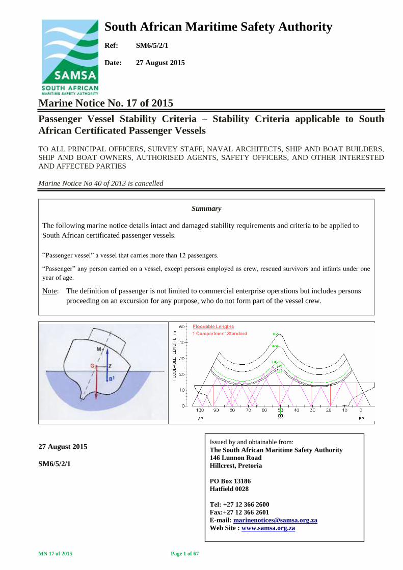
c. With the vessel in its fully loaded condition including passengers, crew and fuel, the freeboard at the
lowest point may not be less than 381 millimetres for vessels not exceeding 6,1 metres inlength and 762
millimetres for vessels of 18,3 metres in length; for vessels of intermediate length, the freeboard is to be
obtained by linear interpolation. Freeboard is measured as follows for the following vessel types:
i. Decked or Open Vessel
ii. Decked Vessel – Scuppers
iii. Pontoon Vessel
WATERLINE
MARGIN LINE
SCUPPERS
DECK DECK
WATERLINE
SCUPPERS
(2) (1) DECK
END VIEW
L2
L1
W2
W1
W1 L1 – FULL LOAD WATERLINE (SYMMETRICAL LOADING)
W2 L2 – MAXIMUM HEELING MOMENT WATERLINE (PASSENGER CROWDING)
AREA (B)
AREA (A)
WITH THE PASSENGER LOAD IN THE EXTREME OUTBOARD POSITION;
AREA (B) MUST BE EQUAL TO OR GREATER THAN AREA (A).
MN 17 of 2015 Page 9 of 67
Note: Application of the minimum freeboard criteria applies primarily to vessels provided with watertight sub-
division for compliance with applicable criteria. Some latitude may be applied by Principal Officers for vessels
provided with built-in buoyancy or a combination of watertight sub-division and built-in buoyancy to achieve
compliance provided that compliance with all other criteria is achieved.
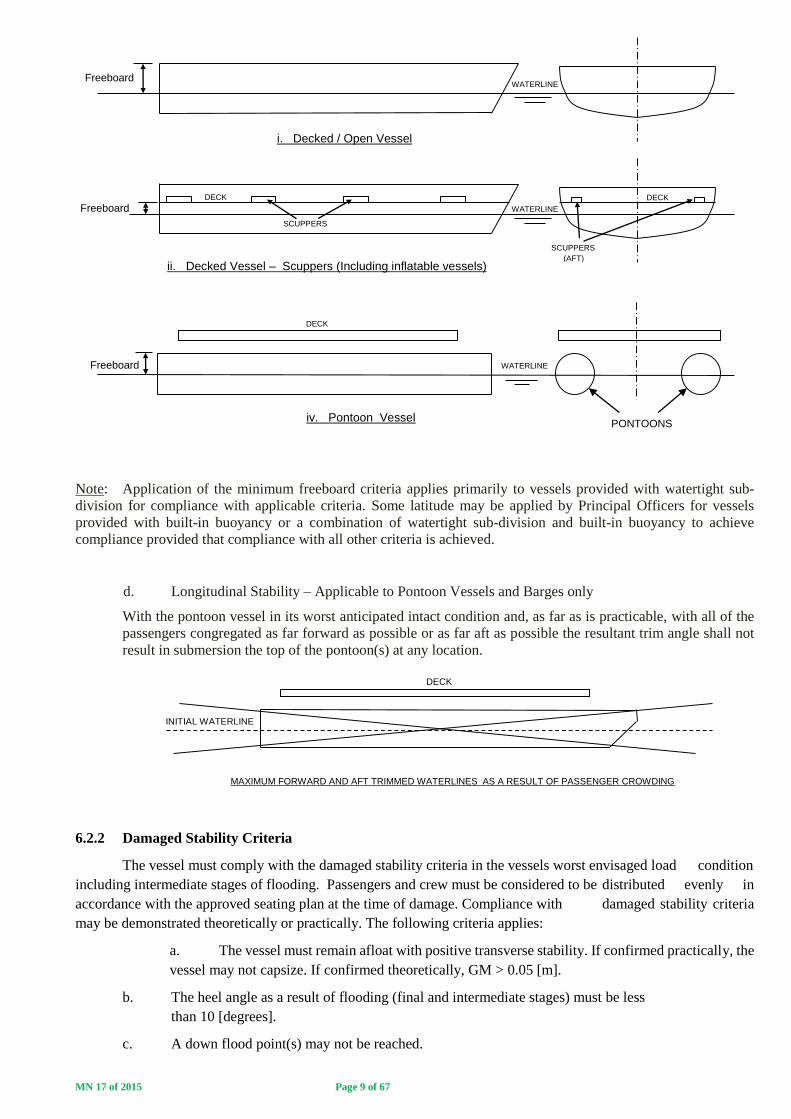
d. Longitudinal Stability – Applicable to Pontoon Vessels and Barges only
With the pontoon vessel in its worst anticipated intact condition and, as far as is practicable, with all of the
passengers congregated as far forward as possible or as far aft as possible the resultant trim angle shall not
result in submersion the top of the pontoon(s) at any location.
6.2.2 Damaged Stability Criteria
The vessel must comply with the damaged stability criteria in the vessels worst envisaged load condition
including intermediate stages of flooding. Passengers and crew must be considered to be distributed evenly in
accordance with the approved seating plan at the time of damage. Compliance with damaged stability criteria
may be demonstrated theoretically or practically. The following criteria applies:
a. The vessel must remain afloat with positive transverse stability. If confirmed practically, the
vessel may not capsize. If confirmed theoretically, GM > 0.05 [m].
b. The heel angle as a result of flooding (final and intermediate stages) must be less
than 10 [degrees].
c. A down flood point(s) may not be reached.
WATERLINE Freeboard
i. Decked / Open Vessel
SCUPPERS (AFT)
SCUPPERS
DECK DECK
WATERLINE Freeboard
ii. Decked Vessel – Scuppers (Including inflatable vessels)
DECK
WATERLINE Freeboard
PONTOONS iv. Pontoon Vessel
DECK
INITIAL WATERLINE
MAXIMUM FORWARD AND AFT TRIMMED WATERLINES AS A RESULT OF PASSENGER CROWDING

MN 17 of 2015 Page 10 of 67
d. If confirmed theoretically, the maximum righting lever must be greater than 0.05m and range of
positive righting lever must be greater than 7 degrees for intermediate stages of flooding.
e. It must be endeavoured to ensure that the vessel configuration is such that deck-edge immersion
does not take place as a result of specified damage. In the event of deck-edge immersion taking
place as a risk assessment is required to be carried out to determine the vessel risk resulting
from the water on deck with respect to down flood points and potential free surface to the
satisfaction of SAMSA.
6.3 BUILT-IN BUOYANCY VERSUS WATERTIGHT SUB-DIVISION
Compliance with damaged stability criteria may normally be achieved through the provision of built-in
buoyancy or watertight sub-division or a combination of the two. The NSVR requires however that
damaged stability compliance be achieved through the provision of built-in buoyancy only4.
Owners/Builders wishing to achieve compliance with damaged stability criteria through the provision of
watertight sub-division arrangements or a combination of watertight sub-division and built-in buoyancy
are required to apply to SAMSA for an exemption from the built-in buoyancy requirement. The
application for exemption must include information on:
a. Means of inspecting/ascertaining the condition of the sub-divided compartments.
b. Means of draining or pumping out the sub-divided compartments.
c. Number of penetrations through the watertight bulkheads, there specific location and proposed
means of making the penetrations watertight.
6.4 EXTENT OF DAMAGE FOR APPLICATION OF DAMAGED STABILITY CRITERIA
In cases where watertight sub-division is accepted by SAMSA as an alternative to the provision of built-
in buoyancy, the following longitudinal, transverse and vertical extents of damage shall apply.
6.4.1 Longitudinal Extent of Damage (Bottom or Side)5
6.4.1.1 The longitudinal extent of damage shall be the greater of:
a. The length of one compartment; or,
b. A length of 0.8 + 0.1 L [m]; where L = Length Overall of the Vessel.
Vessels shall be required to survive the flooding of any one compartment or more than one
compartment in the event that the length defined in paragraph 6.4.1.1.b spans more than one
compartment.
The damage length shall be measured from the point at which the design waterline intersects with the
bow of the bow and then aft from each watertight bulkhead from forward to aft. At the stern the damaged
length shall be measured forward from the point at which the design waterline intersects the stern. The
principle is illustrated in the sketch below with the damaged length, dL, indicated by the length of the arrow. In the
example, the damaged length crosses the watertight bulkhead forward of the stern meaning that the
longitudinal extent of damage for the vessel would include compartment 4 and compartment 5.
4 NSVR Regulation 6, Annex 1(3) 5 NSVR and SAMSA derivation

MN 17 of 2015 Page 11 of 67
6.4.1.2 In the case of inflatable boats, the longitudinal extent of damage to the inflatable chamber shall be the
greater of:
a. Two adjacent inflatable chambers; or,
b. A length of 0.8 + 0.1L [m].
In the case of rigid hulled inflatable boats the rigid hull must be considered damaged as per paragraph 6.4.1.1.
The longitudinal extent of damage of each hull element (inflatable hull section and rigid hull section) is
determined separately but considered to occur simultaneously.
6.4.1.3 Raking Damage For high speed vessels raking damage shall additionally be considered as follows:
Any part of the surface of the hull(s) is considered vulnerable to raking damage if:
a. It is in contact with the water at 90% of maximum speed in smooth water.
b. It also lies below two planes which are perpendicular to the craft centreline plane and at heights
shown in the below figure.
For multihulls, individual hulls are considered separately.
Two different longitudinal extents shall be considered separately:
a. 55% of length, L, measured from the most forward point of the underwater buoyant volume of
each hull; and
b. a percentage of L, applied anywhere along the length of the craft equal to (L/2 + 10)%.
6.4.2 Transverse Extent of Damage
The transverse extent of damage shall be a transverse penetration into the hull of at least 350mm.
In the case of multi-hull or pontoon vessels, damage to one hull only is to be considered, however, if the
transverse extent of damage described above results in damage to more than one hull then this damage must
also be evaluated.
The extent of damage must be considered to occur at any point on the hull, from the keel to the bulkhead
deck, and to penetrate to the transverse extent defined above.
dL dL dL dL dL
MAIN DECK
DESIGN WATERLINE
1 3 4
5
2
This area is vulnerable to
raking damage
T 0.3T DESIGN WATERLINE
0.5L L
This line is parallel to
the design waterline
T = Maximum draught of the hull (Each hull considered individually in the case of multihulls) to the design waterline, excluding any non-buoyant structure, provided that structures such as single
plate skegs or solid metal appendages shall be considered to be non-buoyant and thus excluded.
MN 17 of 2015 Page 12 of 67
For raking damage the transverse penetration of the damage shall be 0.04 1/3 or 0.5m acting
perpendicular to the shell from the bottom plating up the side of the hull as far as the vertical extent
defined in the drawing above (paragraph 5.4.1.4).
6.4.3 Vertical Extent of Damage
For standard damage the vertical extent of damage shall be taken as the full vertical extent of the buoyant
part of the hull defined by the “enclosed volume”.
For raking damage the vertical extent of damage shall be as defined in the sketch in paragraph 4.2.1.2.
6.4.4 Use of Class V or VI Passenger Vessel Extents of Damage
The extent of damage definitions for class V or VI passenger vessels (Para 5.2) may be used in lieu of
the above if requisite information is available.
6.5 PERMEABILITY OF DAMAGED COMPARTMENTS
6.5.1 General For the purpose of making damaged stability calculations, the permeability of compartments
should be taken as follows:
a. Spaces occupied by cargo or stores – 60%
b. Spaces occupied by accommodation – 95%
c. Spaces occupied by machinery – 85%
d. Spaces occupied by liquids – 0% or 95%, whichever results in the more severe case.
e. Void spaces – 95%
Notwithstanding the above, compartment permeability determined by direct calculation shall be used
when a more onerous condition results and may be used where a less onerous condition results.
6.5.2 Built-in Buoyancy Where approved built-in buoyancy is used to reduce the permeability of a
compartment(s), the compartment(s) permeability shall be determined by direct calculation.
7. PASSENGER DISTRIBUTION
7.1 General
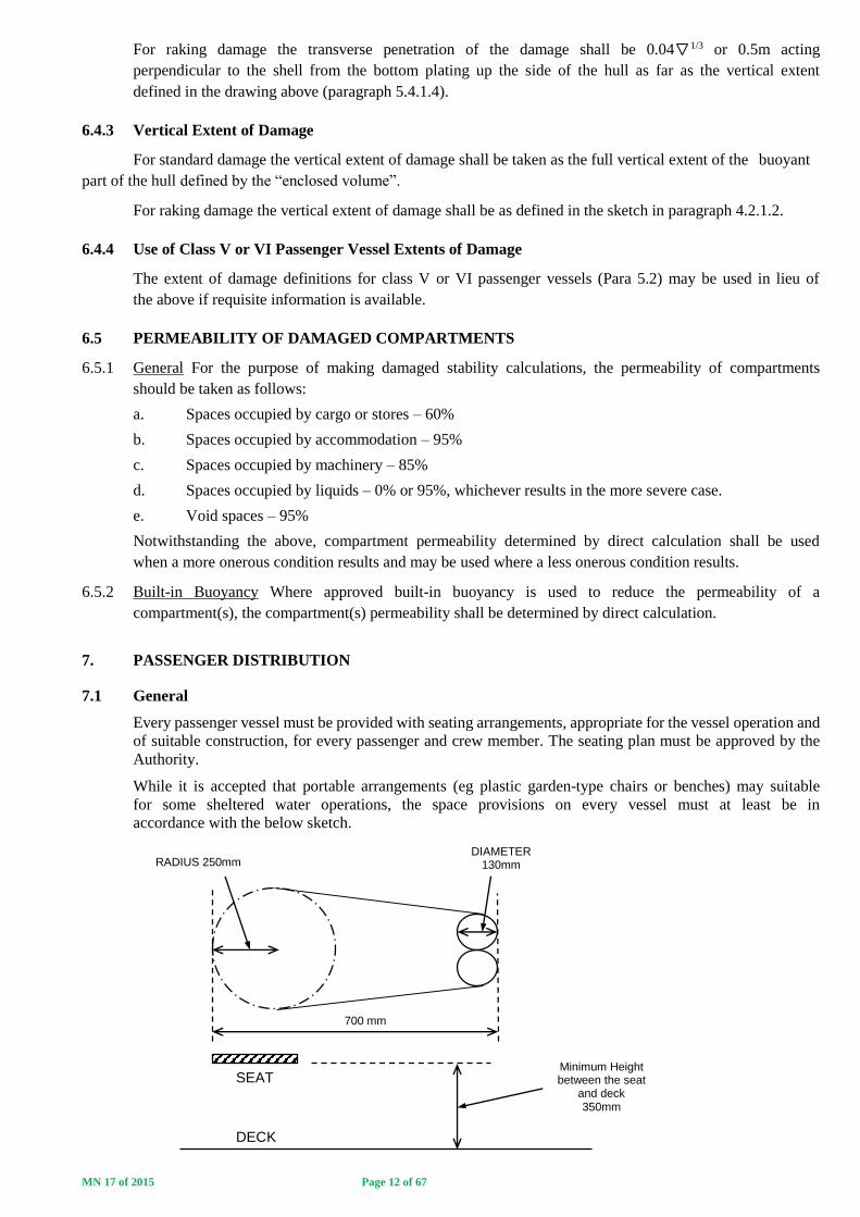
Every passenger vessel must be provided with seating arrangements, appropriate for the vessel operation and
of suitable construction, for every passenger and crew member. The seating plan must be approved by the
Authority.
While it is accepted that portable arrangements (eg plastic garden-type chairs or benches) may suitable
for some sheltered water operations, the space provisions on every vessel must at least be in
accordance with the below sketch.
700 mm
DIAMETER 130mm
SEAT
DECK
Minimum Height between the seat
and deck 350mm
RADIUS 250mm
MN 17 of 2015 Page 13 of 67
Note: For trailer-borne passenger vessels, the minimum seat width may be reduced to 450mm.
7.2 Passenger Weights and Centres of Gravity
Intact stability criteria for class V, VI, and small passenger vessels requires consideration of vessel heel
due to application of a maximum passenger heeling moment. Damaged stability criteria requires that
the passengers and crew be considered to be distributed normally in accordance with the approved
seating plan at the time of damage.
Where consideration of the effects of a passenger weight, for compliance with intact and damaged
stability criteria the following principals shall apply:
a. Each passenger has a mass of 82.5 kg6.
b. Vertical centre of seated passengers is 0.3 m above the seat.
c. Vertical centre of standing passengers is 1.0 m above the deck.
d. The “crowded” distribution of passenger is 4 persons per square metre.
e. When conducting practical heel testing is carried out, passengers must congregate to one
side, as far as is practicable (“crowded” distribution), to create a worst case heeling condition.
7.3 Stability File Information and Special Stability Instructions
Stability files for the above passenger vessels must include drawings/descriptions of the assumed
passenger distributions for application of intact and damaged stability criteria. A note must further be
included in the “Special Stability Instructions” of the stability file (for reference of the master/skipper) to
the effect that a normal passenger distribution is considered for the event of damage and advice should
be provided on the use of passengers to counter the vessel list as a result of the damage.
8. FORM AND APPROVAL OF STABILITY INFORMATION
Stability information must be submitted in a form acceptable to the Authority. As a minimum compliance
with applicable stability criteria must be shown in the Departure and Arrival load conditions and in any
other condition which represents the worst case loading condition(s).
Stability information of all passenger vessels must be approved by SAMSA7. The following approaches
may be followed:
6 The weight of passengers for existing passenger vessels is to taken as 75 kg. The weight of passengers on passenger vessels constructed or registered after the date of promulgation of this marine notice shall be taken as 82.5 kg. 7 SoN Regulation 7 and Marine Notice 6 of 2000. NSVR Regulation 6, Annex 1(16) and this marine notice.

MN 17 of 2015 Page 14 of 67
8.1 CLASS 1, II, IIA, V AND VI PASSENGER VESSELS AND SMALL PASSENGER VESSELS
CARRYING MORE THAN 20 PASSENGERS IF PROCEEDING TO SEA OR CARRYING MORE
THAN 30 PASSENGERS IF OPERATING ON SHELTERED WATERS.
For class I, II, IIA, V, VI passenger vessels it is always required that the hull (enclosed volume) of the
vessel be modelled in a hydrostatics program for determination of stability curves. The inclining
experiment is in all cases carried out by an external naval architect and the subsequently generated
stability information is submitted to SAMSA for approval as described in the below flow chart.
In some cases, the calculation of lightship particulars and load conditions is combined by the external
naval architect and then submitted to SAMSA for review.
8.2 SMALL PASSENGER VESSELS CARRYING A MAXIMUM OF 20 PASSENGERS IF
PROCEEDING TO SEA OR CARRYING A MAXIMUM OF 30 PASSENGERS IF OPERATING ON
SHELTERED WATERS.
The NSVR provides that compliance with stability criteria (intact and damaged stability) may be
confirmed theoretically or practically. Where stability compliance is confirmed practically, the testing is
witnessed and recorded by a SAMSA surveyor using a “Small Passenger Vessel Stability Record” form
(See Annex 2). The following flow chart illustrates the processes which may be followed to achieve
SAMSA approval of stability information.
SATISFACTORY ?
SATISFACTORY
?
CONDUCT OF INCLINING EXPERIMENT BY EXTERNAL NAVAL ARCHITECT
(SAMSA TO WITNESS)
LIGHTSHIP PARTICULARS CALCULATED AND
SUBMITTED FOR APPROVAL
NO
YES
LOAD CONDITIONS SUBMITTED FOR APPROVAL
REMARKS REFERRED BACK
TO EXTERNAL NAVAL ARCHITECT
YES
NO
STABILITY BOOK APPROVED BY SAMSA
REMARKS REFERRED BACK TO EXTERNAL NAVAL
ARCHITECT

MN 17 of 2015 Page 15 of 67
Remarks:
(1) OPTION A Where the small passenger vessel intact and damaged stability is confirmed practically,
the practical confirmation is carried out by the owner and witnessed by a SAMSA surveyor. The following
principles apply for practical stability testing. It is the owner/owner representatives responsibility to prepare
the vessel and conduct the heeling tests (The role of the SAMSA surveyor is to provide guidance, witness
YES YES
YES YES
YES
NO NO
NO NO
NO
TO BE CONFIRMED BY HYDROSTATIC MODELLING (OPTION C)
TO BE CONFIRMED PRACTICALLY (OPTION A)
TO BE CONFIRMED THEORETICALLY (OPTION B)
SMALL PASSENGER VESSEL PRACTICAL / THEORETICAL STABILITY EVALUATION
DAMAGE STABILITY
SURVIVABILITY CONFIRMATION
OWNER OR THEIR NAVAL ARCHITECT/YACHT DESIGNER/PROFESSIONAL ENGINEER TO PRESENT THEORETICAL CALCULATIONS TO THE SURVEYOR TO PROVE THAT THE THAT THE VESSEL WILL REMAIN AFLOAT WITH POSITIVE TRANSVERSE STABILITY IN THE EVENT OF DAMAGE (EXTENT OF DAMAGE; dL = 0.8 + 0.1L) AS A RESULT OF THE VESSELS SURVIVABILITY PROVISIONS; VIZ, - BUILT-IN BUOYANCY - WATERTIGHT SUB-DIVISION
CONDUCT PRACTICAL INTACT STABILITY EVALUATION
COMPLETE INTACT STABILITY SECTIONS OF SMALL PASSENGER VESSEL RECORD FORM (SIGNED BY SURVEYOR). COMPLETE THEORETICAL DAMAGE STABILITY SECTION OF STABILITY RECORD FORM (SUPPLEMENTED WITH OWNER CALCULATIONS, IF APPLICABLE)
COMPLETE SMALL PASSENGER VESSEL STABILITY RECORD FORM (SIGNED BY BY SURVEYOR AND APPROVED BY PRINCIPAL OFFICER
ISSUE TO OWNER (TO BE RETAINED ON BOARD WITH LOCAL GENERAL SAFETY CERTIFICATE) (SAMSA COPY TO BE RETAINED ON FILE)
CONDUCT PRACTICAL INTACT STABILITY EVALUATION
CORRECTIVE ACTION Eg.REDUCE PAX No’s
CORRECTIVE ACTION Eg.REDUCE PAX No’s
CONDUCT PRACTICAL DAMAGE STABILITY
EVALUATION
CORRECTIVE ACTION
EXTERNAL NAVAL ARCHITECT TO MODEL VESSEL AND
PROVE INTACT AND DAMAGED STABILITY COMPLIANCE. STABILITY STATEMENT
GENERATED
SUBMIT TO SAMSA NAVAL ARCHITECT
FOR APPROVAL
CORRECTIVE ACTION
STABILITY STATEMENT APPROVED BY SAMSA PRINCIPAL OFFICER
SATISFACTORY ?
SATISFACTORY
?
SATISFACTORY ?
SATISFACTORY ?
SATISFACTORY ?

MN 17 of 2015 Page 16 of 67
the practical testing and to record and evaluate the results). SAMSA will provide guidance to owners for the
conduct of the practical tests.
(2) OPTION B In some cases the vessels construction is such that theoretical damage evaluation can be
carried out without recourse to a hydrostatics program with owners/owners representatives able to
confirm compliance with statutory criteria using Archimedes principle and basic geometry calculations.
This approach has limitations, however, and;
a. is not accepted by SAMSA to evaluate a vessels intact stability characteristics.
b. will only be accepted by SAMSA to evaluate a vessels damaged stability characteristics:
i. For vessel’s provided with built-in buoyancy in the hull, evenly distributed below
deck (to avoid trim effects in the event of flooding), where it can be shown that a vessel is
provided with additional built-in buoyancy equal to at least 100% of the vessel weight in its
worst case loaded condition.
ii. For multihull or pontoon vessels, with simple hull geometry’s, provided with
watertight sub-division where it can be shown that the remaining buoyancy in a damaged
pontoon is sufficient to ensure that the vessel remains afloat with positive transverse
stability.
ie. The vessel may not capsize.
For this option the intact stability characteristics are confirmed practically with a SAMSA surveyor
witnessing the tests and the theoretical damaged stability evaluation must be submitted to a SAMSA Naval
Architect for approval.
(3) OPTION C In the majority of cases, the theoretical approval process will be as for a class I, II, IIA, V or
VI passenger vessel, however in some cases where a small passenger vessel may have a large
metacentric height eg multihull vessel, pontoon vessel or a barge, SAMSA may exempt owners from
the requirement of an inclining experiment provided that:
(a) The vessel weight is accurately determined (by calculation, weighing or draught survey) and
the centres of gravity theoretically calculated with application of a satisfactory safety margin (at least 10%
on vertical centre of gravity)
(b) A stability prognosis is submitted to SAMSA as part of the application for the exemption.
(c) A draught survey is carried out on the vessel to confirm the displacement and longitudinal and
transverse centre of gravity calculations submitted to SAMSA.
(4) In all cases passenger vessels are required to be provided with approved stability information for their
operation for the reference of the master/skipper.
9. CONCLUSION
This marine notice details intact and damaged stability criteria to be applied to South African registered
or licenced passenger vessels and may be reviewed from time to time.
SAMSA should be contacted if clarification or interpretation of criteria applicable to passenger vessels
addressed in this marine notice is required.

MN 17 of 2015 Page 17 of 67
ANNEX 1
CLASS V & VI PASSENGER VESSELS
INTACT AND DAMAGED STABILITY CRITERIA FOR MONOHULL AND MULTIHULL CRAFT
The intact and damaged stability criteria shall be applied to monohull and multihull craft as follows:
GMT
Angle of Maximum GZ
≤ 25o > 25o
≤ 3 m Monohull (A) or Multihull (B) Criteria Monohull (A) Criteria only
> 3 m Multihull(B) Criteria only Monohull (A) or Multihull (B) Criteria
STABILITY CRITERIA FOR MONOHULL CRAFT (A)
1 Stability criteria in the intact condition
1.1 General Criteria
1.1.1 The area under the righting lever curve (GZ curve) shall not be less than 0.07 m.rad up to Ө = 15o when the maximum
righting lever (GZ) occurs at Ө = 15o, and 0.055 m.rad up to Ө = 30o when the maximum righting lever occurs at Ө =
30o or above. Where the maximum righting lever occurs at angles of between Ө = 15o and Ө = 30o, the corresponding
area under the righting lever curve shall be:
A = 0.055 + 0.001 (30o - Өmax ) (m.rad)
where: Өmax is the angle of heel, in degrees, at which the righting lever curve reaches its maximum.
1.1.2 The area under the righting lever curve between Ө = 30o and Ө = 40o or between Ө = 30o and the angle of flooding ӨF,
if this angle is less than 40°, shall not be less than 0.03 m.rad.
1.1.3 The righting lever GZ shall be at least 0.2 m at an angle of heel equal to or greater than 30°.
1.1.4 The maximum righting lever shall occur at an angle of heel not less than 15°.
1.1.5 The initial metacentric height GMT shall not be less than 0.15 m.
1.2 Weather Criterion
The weather criterion contained in the Intact Stability Code shall apply. In applying the weather criterion the values of
wind pressure, P, shall be taken as per the below table8:
h (m) 1 2 3 4 5 6 and over
P (Pa) 316 386 429 460 485 504
Where h is the vertical distance of the centre of the projected vertical area of the ship above the waterline, to the
waterline.
In determining the value of the wind pressure to be applied, the calculated value of h shall be rounded up to the nearest
metre eg. If the calculated value of h = 2.15m, then use; h= 3m and P = 429 Pa.
The angle of heel due to wind shall not exceed 16o or 80% of the angle of deck-edge immersion (whichever is less).In
applying the weather criterion account shall also be taken of the roll damping characteristics of individual craft in
assessing the assumed roll angle Ө1. Hulls with features which greatly increase damping, such as immersed sidehulls,
substantial arrays of foils, or flexible skirts or seals, are likely to experience significantly smaller magnitudes of roll
angle. For such craft, therefore, the roll angle shall be derived from model or full-scale tests or in the absence of such
data shall be taken as 15°.
8 Code on Intact Stability – weather criterion for fishing vessels between 24m and 45m
MN 17 of 2015 Page 18 of 67
1.3 Maximum Passenger Heeling
With the vessel in the worst anticipated intact condition and, as far as is practicable, with all of the passengers
congregated on one side (See paragraph 7.2 of this marine notice for crowding distribution and centres of gravity), the
resultant heel angle shall not exceed 10o.
1.4 High Speed Turning
In addition for passenger ships, the angle of heel on account of turning should not exceed 10° when calculated using
the following formula:
MR = 0.196 × Vo2 × Δ × (KG - d/2)/L
where: MR = heeling moment in kNm,
Vo = service speed in m/s,
L = length of ship at waterline in m,
Δ = displacement in tonnes,
d = mean draught in m,
KG = height of centre of gravity above baseline in m
2 Criteria for residual stability after damage
2.1 The stability required in the final condition after damage, and after equalization where provided, shall be
determined as specified in 2.1.1 to 2.1.4.
2.1.1 The positive residual righting lever curve shall have a minimum range of 0.015 m.rad beyond the angle of equilibrium.
This range may be reduced to a minimum of 15°, in the case where the area under the righting lever curve is that
specified in 2.1.2, increased by the ratio:
15/range
where the range is expressed in degrees. The range shall be taken as the difference between the equilibrium heel angle
at which the residual righting lever subsequently becomes negative or the angle at which progressive flooding occurs,
whichever is less.
2.1.2 The area under the righting lever curve shall be at least 0.015 m.rad, measured from the angle of equilibrium to the
lesser of:
.1 the angle at which progressive flooding occurs; and
.2 27o measured from the upright.
2.1.3 A residual righting lever shall be obtained within the range of positive stability, taking into account the heeling moment
due to a wind pressure, P = 120 Pa, as calculated by the formula:
GZ = (Heeling mom. / disp.) + 0.04m
Where; Heeling moment = 𝑃𝐴ℎ
9800
A = the projected lateral area of the ship above the waterline corresponding to the
intact condition.
h = vertical distance of the centre of the projected vertical area of the ship above
the waterline, to the waterline.
However, in no case shall the righting lever be less than 0.1 m.
The resultant angle of heel as a result of damage and beam wind pressure shall not exceed 10o.
2.2 In intermediate stages of flooding, the maximum righting lever shall be at least 0.05m and the range of positive righting
levers shall be at least 7°. In all cases, only one breach in the hull and only one free surface need be assumed.

MN 17 of 2015 Page 19 of 67
STABILITY CRITERIA FOR MULTIHULL CRAFT (B)
1 Stability criteria in the intact condition
A multihull craft, in the intact condition, shall have sufficient stability when rolling in a seaway to successfully
withstand the effect of either passenger crowding or high-speed turning as described in paragraph1.4. The craft's
stability shall be considered to be sufficient provided compliance with this paragraph is achieved.
1.1 Area under the GZ curve
The area (A1) under the GZ curve up to an angle Ө shall be at least:
A1 = 0.055 x 30°/Ө (m.rad)
where Ө is the least of the following angles:
.1 the downflooding angle;
.2 the angle at which the maximum GZ occurs; and
.3 30o
1.2 Maximum GZ
The maximum GZ value shall occur at an angle of at least 10°.
1.3 Heeling due to wind
The wind heeling lever shall be assumed constant at all angles of inclination and shall be calculated
as follows:
Where, the value of wind pressure, Pi shall be taken as per the below table9:
h (m) 1 2 3 4 5 6 and over
P (Pa) 316 386 429 460 485 504
Where h is the vertical distance of the centre of the projected vertical area of the ship above the waterline, to the
waterline.
In determining the value of the wind pressure to be applied, the calculated value of h shall be rounded up to the nearest
metre eg. If the calculated value of h = 2.15m, then use; h= 3m and P = 429 Pa.
and: A = projected lateral area of the portion of the craft above the lightest service waterline (m2)
Z = vertical distance from the centre of A to a point one half the lightest service draught (m)
∆ = displacement (t)
1.4 Heeling due to passenger crowding or high-speed turning
Heeling due to the crowding of passengers on one side of the craft or to high-speed turning, whichever is the greater,
shall be applied in combination with the heeling lever due to wind (HL2).
1.4.1 Heeling due to passenger crowding
When calculating the magnitude of the heel due to passenger crowding, a passenger crowding lever shall be
developed using the assumptions stipulated on paragraph 6 of this marine notice.
1.4.2 Heeling due to high-speed turning
When calculating the magnitude of the heel due to the effects of high-speed turning, a high-speed turning lever shall
be developed using either the following formula or an equivalent method specifically developed for the type of craft
under consideration, or trials or model test data:
9 Code on Intact Stability – weather criterion for fishing vessels between 24m and 45m
MN 17 of 2015 Page 20 of 67
where: TL = turning lever (m) R = turning radius (m)
Vo= speed of craft in the turn (m/s) d = mean draught (m)
KG = height of vertical centre of gravity above keel (m) g = acceleration due to gravity
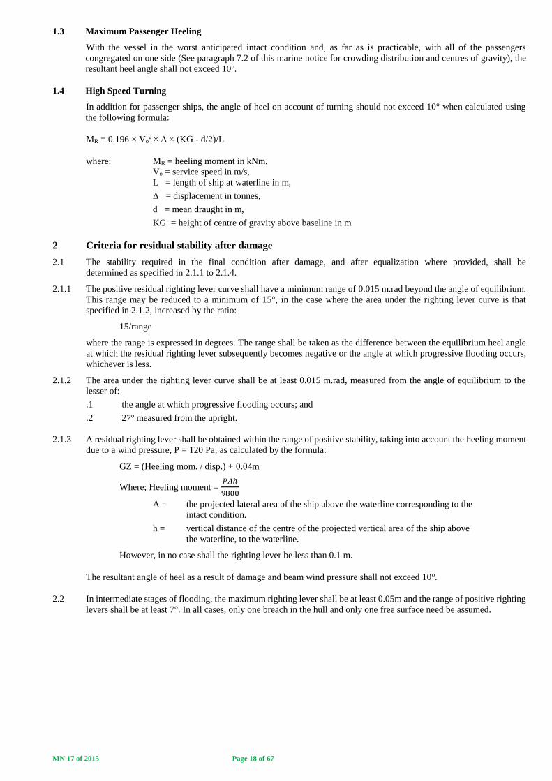
1.5 Rolling in waves (figure 1)
The effect of rolling in a seaway upon the craft's stability shall be demonstrated mathematically. In doing so, the
residual area under the GZ curve (A2), i.e. beyond the angle of heel Өh, shall be at least equal to 0.028 m.rad up to the
angle of roll Өr. In the absence of model test or other data Өr shall be taken as 15o or an angle of (Өd - Өh), whichever
is less.
In calculating the residual area, the heeling lever used shall be the heeling lever due to wind, HL3 ie. In figure 2; HL3
= HL4
Figure 1 - Intact stability
Abbreviations used in figure 1
HL2 = Heeling lever due to wind + gusting
HTL = Heeling lever due to wind + gusting + (passenger crowding or turning)
Өm = Angle of maximum GZ
Өd = Angle of downflooding
Өr = Angle of roll
Өe = Angle of equilibrium, assuming no wind, passenger crowding or turning effects
Өh = Angle of heel due to heeling lever HL2, HTL, HL3 or HL4
A1 ≥ Area required by 1.1
A2 ≥ 0.028 m.rad
2 Criteria for residual stability after damage
2.1 The method of application of criteria to the residual stability curve is similar to that for intact stability except that the
craft in the final condition after damage shall be considered to have an adequate standard of residual stability
provided:
.1 the required area A2 shall be not less than 0.028 m.rad (figure 2 refers); and
.2 there is no requirement regarding the angle at which the maximum GZ value shall occur.
2.2 The wind heeling lever for application on the residual stability curve shall be assumed constant at all angles of
inclination and shall be calculated as follows:
where:
Pd = 120 Pa
A = projected lateral area of the portion of the ship above the lightest service waterline (m2)
Z = vertical distance from the centre of A to a point one half of the lightest service draught (m)
∆ = displacement (t)

MN 17 of 2015 Page 21 of 67
2.3 The same values of roll angle shall be used as for the intact stability.
2.4 The downflooding point is important and is regarded as terminating the residual stability curve. The area A2 shall
therefore be truncated at the downflooding angle.
2.5 The stability of the craft in the final condition after damage shall be examined and shown to satisfy the criteria, when
damaged as stipulated in paragraph 4 of this Marine Notice.
2.6 In the intermediate stages of flooding, the maximum righting lever shall be at least 0.05 m and the range f positive
righting lever shall be at least 7°. In all cases, only one breach in the hull and only one free surface need to be
assumed.
3 Application of heeling levers
3.1 In applying the heeling levers to the intact and damaged curves, the following shall be considered:
3.1.1 for intact condition:
.1 wind heeling lever (including gusting effect) (HL2); and
.2 wind heeling lever (including gusting effect) plus either the passenger crowding or speed
turning levers whichever is the greater (HTL).
3.1.2 for damage condition:
.1 wind heeling lever - steady wind (HL3).
3.2 Angles of heel due to steady wind
3.2.1 The angle of heel due to a wind gust when the heeling lever HL2, obtained as in 1.3, is applied to the intact stability
curve shall not exceed 10°.
3.2.2 The angle of heel due to a steady wind when the heeling lever HL3, obtained as in 2.2, is applied to the residual
stability curve, after damage, shall not exceed 10o.
Figure 2 - Damage stability
Abbreviations used in figure 2
HL3 = Heeling lever due to wind = HL4
Өm = Angle of maximum GZ
Өd = Angle of downflooding
Өr = Angle of roll
Өe = Angle of equilibrium, assuming no wind, passenger crowding or turning effects
Өh = Angle of heel due to heeling lever HL2, HTL, HL3 or HL4
A1 ≥ Area required by 1.1
A2 ≥ 0.028 m.rad
MN 17 of 2015 Page 22 of 67
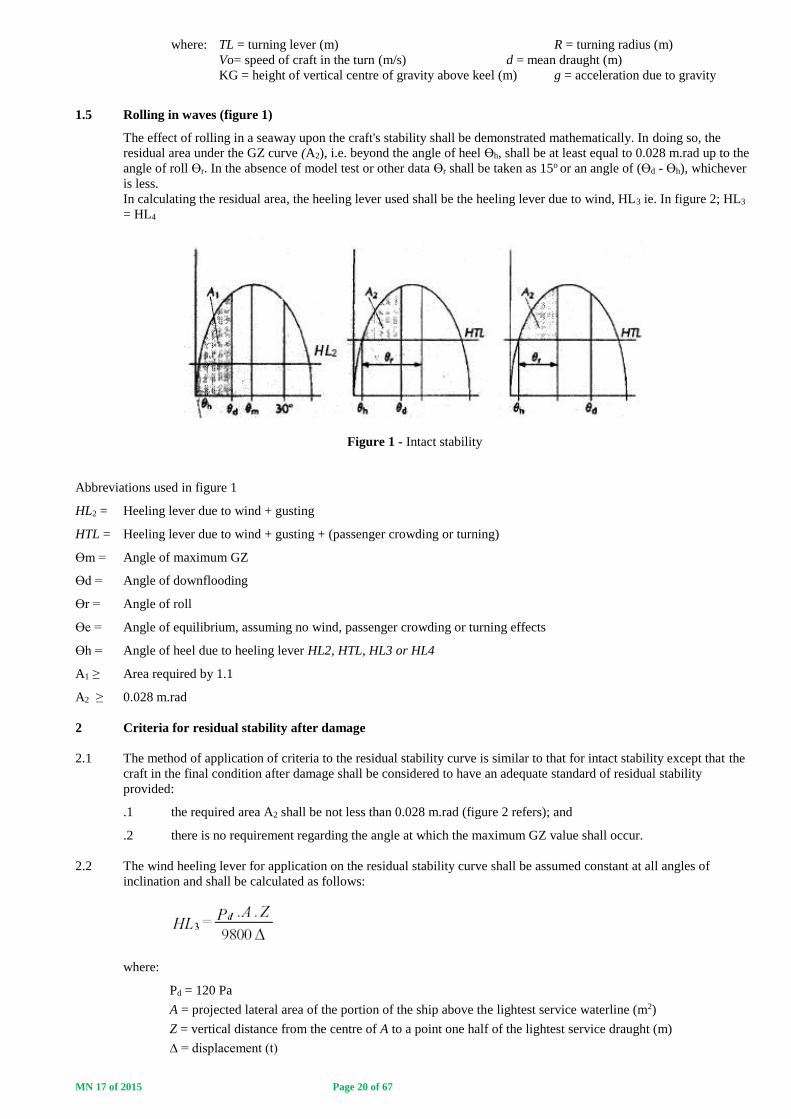
ANNEX 2
SMALL PASSENGER VESSEL STABILITY RECORD FORM
SMALL PASSENGER VESSEL
STABILITY RECORD FORM
OFFICIAL NUMBER:
AREA OF OPERATION:
MAXIMUM NUMBER OF PERSONS:
________________________________________ ____________________
PRINCIPAL OFFICER SIGNATURE DATE
MN 17 of 2015 Page 23 of 67
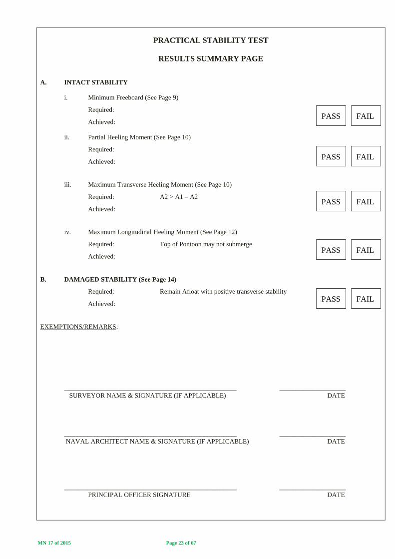
PRACTICAL STABILITY TEST
RESULTS SUMMARY PAGE
A. INTACT STABILITY
i. Minimum Freeboard (See Page 9)
Required:
Achieved:
ii. Partial Heeling Moment (See Page 10)
Required:
Achieved:
iii. Maximum Transverse Heeling Moment (See Page 10)
Required: A2 > A1 – A2
Achieved:
iv. Maximum Longitudinal Heeling Moment (See Page 12)
Required: Top of Pontoon may not submerge
Achieved:
B. DAMAGED STABILITY (See Page 14)
Required: Remain Afloat with positive transverse stability
Achieved:
EXEMPTIONS/REMARKS:
____________________________________________________ ____________________
SURVEYOR NAME & SIGNATURE (IF APPLICABLE) DATE
____________________________________________________ ____________________
NAVAL ARCHITECT NAME & SIGNATURE (IF APPLICABLE) DATE
____________________________________________________ ____________________
PRINCIPAL OFFICER SIGNATURE DATE
PASS FAIL
PASS FAIL
PASS FAIL
PASS FAIL
PASS FAIL

MN 17 of 2015 Page 24 of 67
GENERAL INFORMATION
This stability record form is used for recording the results of stability tests and calculations carried out to confirm that small
passenger vessels comply with the requirements of the Merchant Shipping (National Small Vessel Safety) Regulations, 2007
(NSVR).
Only SAMSA officers may carry out surveys of small passenger vessels for the issue of an appropriate Local General Safety
Certificate.
When correctly completed and signed by the attending SAMSA surveyor/NA and approved by the Principal Officer of a port or
Proper Officer of an inland region, this stability record form demonstrates the vessels compliance with intact and damaged
stability requirements of the NSVR. Complete and approved forms must be retained with the vessels LGSC for reference of the
owner and skipper and for presentation at the time of survey and on the vessels file in SAMSA port offices.
APPLICATION
This form may only be used for the following small passenger vessel operations:
a. Category D or E vessel carrying not more than 20 passengers.
b. Category R vessel carrying not more than 30 passengers.
Notes:
- No passenger vessel may be operated more than 5 nm from shore and 15 nm from a safe haven.
The following parts of this form must be completed:
a. Monohull - Parts A, B, C, F
b. Multihull - Parts A, B, D, F
c. Pontoon Vessel - Parts A, B, E, F
d. Barges - Parts A, B, C, E7 & F.
NB - Part F relates to the vessels ability to survive reasonable damage ie. Damaged stability characteristics. The vessels
intact stability evaluation should not be carried out unless there is a clear understanding of how the vessels damaged stability
compliance will be demonstrated (See explanatory flow chart on the next page).
OPTIONS IN THE EVENT OF NON-COMPLIANCE
1. If the vessel design/configuration does not allow for measurements and evaluation to be carried out in accordance with
the instructions contained in each part, the test must be stopped and guidance requested from a SAMSA Naval Architect before
proceeding.
2. The procedures outlined for each part must be followed with all criteria required to be complied with. In the
event that criteria are not met, the owner should consider the following options:
a. Reduce the number of passengers/other weights until compliance is achieved.
b. Stop the test and approach a naval architect or professional engineer to carry out more detailed
theoretical calculations or to model the vessel hull and conduct a full stability evaluation.
Note: Surveyors must endeavour to complete required calculations immediately after the conduct of practical testing so that
compliance or not may be confirmed and, if necessary, the owner be allowed the option of reducing passenger numbers, for
example to achieve compliance, thereby avoiding the inconvenience of having to return to the vessel for further testing at a
later date.

MN 17 of 2015 Page 25 of 67
PART A - GENERAL PARTICULARS
Name of Vessel: Off No.
Owner/Representative: Date:
Contact Tel no. email:
SAMSA Surveyor(s): Weather Conditions
Wind:
Location: Water:
Description of Vessel Operation:
Application:
This record form is for the following small passenger vessel operations (Mark the relevant box):
Category D or E vessel carrying not more than 20 passengers.
Category R vessel carrying not more than 30 passengers.
Remarks:
_________________________________________________________________________________________
_________________________________________________________________________________________
This record is or the following vessel type (Mark the relevant box):
Monohull - Parts A, B, C & F completed.
Multihull - Parts A, B, D & F completed.
Pontoon Vessel - Parts A, B, E & F completed.
Barge - Parts A, B, C, E7 & F completed.
Remarks:
PARTS OF THE STABILITY RECORD FORM WHICH ARE NOT RELEVANT TO THE VESSEL TYPE AND OR
EVALUATION CARRIED OUT ARE EXCLUDED FROM THIS RECORD.

MN 17 of 2015 Page 26 of 67
SKETCH OF ENCLOSED VOLUME AND WATERTIGHT SUB-DIVISIONS
Definitions:
a. Enclosed Volume - The enclosed volume of a vessel is the constructed volume which provides the vessel buoyancy and
reserve of buoyancy.
b. Downflood Point - An opening in the boats hull through which progressive flooding could take place which is not able
to be closed watertight (below waterline) or weathertight (Above waterline). Small openings such as small diameter (ø<3mm)
compartment vents are not considered to be downflood points.
c. Watertight Sub-divisions - Divisions within the hull structure which prevent flooding from one compartment to another in
the event of damage.
A sketch of the vessel in plan and profile view must be provided in the space below clearly identifying the enclosed volume,
downflood points and watertight sub-divisions.
NB - Owners must ensure that they do not modify the vessel so that the enclosed volume, downflood points and watertight
sub-divisions are not negatively affected in any way.
Surveyors must confirm that the enclosed volume, downflood points and watertight sub-divisions are as reflected in the above
sketch at the time of vessel inspection.

MN 17 of 2015 Page 27 of 67
PART B – VESSEL PREPARATION AND PREVAILING WEATHER CONDITIONS
The vessel must be prepared and presented for practical stability evaluation as follows:
Initial Vessel Condition:
- The vessel must be in a complete condition ie. Not still under construction.
- The vessel must upright and moored alongside with slack mooring lines.
- The vessel hull(s) must be confirmed free of water.
Vessel Loaded Condition:
The vessel must be initially loaded with all safety and operational equipment on board, excluding crew and passengers. Fuel
and water tanks must be between 75% and 100% full.
Persons or weights may be used to represent the crew and passenger load (Persons/weights must be prepared and ready for use
as required by the attending surveyor).
In the event of weights being utilised, each “passenger/crew” shall be represented by a weight of 82.5 kg.
Standing passengers shall be assumed to congregate at 0.25 m2 per person and their vertical centre of gravity shall be assumed
to be 1.0m above the deck.
Seated passengers shall be provided with a minimum seat spacing of 500mm and their vertical centre of gravity shall be
assumed to be 0.3m above the seat.
In the event of persons being used as “passengers/crew”, the principles outlined above should be applied when distributing
persons in the course of the tests.
Weather Conditions:
The prevailing weather conditions must allow for the required tests to be carried out in a safe and controlled manner and for
freeboard measurements to be accurately taken.
Surveyor Confirmation:
The vessel condition and prevailing weather conditions are considered satisfactory for the conduct of the requisite
testing.
Remarks:
MN 17 of 2015 Page 28 of 67
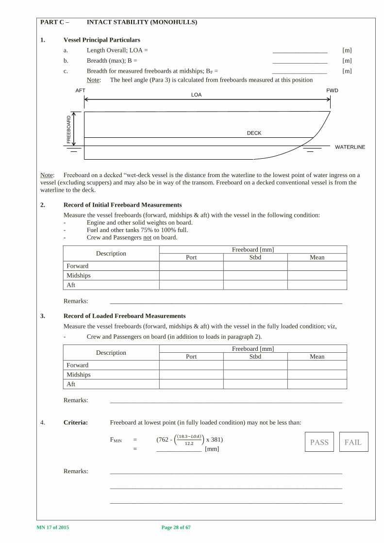
PART C – INTACT STABILITY (MONOHULLS)
1. Vessel Principal Particulars
a. Length Overall; LOA = _________________ [m]
b. Breadth (max); B = _________________ [m]
c. Breadth for measured freeboards at midships; BF = _________________ [m]
Note: The heel angle (Para 3) is calculated from freeboards measured at this position
Note: Freeboard on a decked “wet-deck vessel is the distance from the waterline to the lowest point of water ingress on a
vessel (excluding scuppers) and may also be in way of the transom. Freeboard on a decked conventional vessel is from the
waterline to the deck.
2. Record of Initial Freeboard Measurements
Measure the vessel freeboards (forward, midships & aft) with the vessel in the following condition:
- Engine and other solid weights on board.
- Fuel and other tanks 75% to 100% full.
- Crew and Passengers not on board.
Description Freeboard [mm]
Port Stbd Mean
Forward
Midships
Aft
Remarks: ________________________________________________________________________
3. Record of Loaded Freeboard Measurements
Measure the vessel freeboards (forward, midships & aft) with the vessel in the fully loaded condition; viz,
- Crew and Passengers on board (in addition to loads in paragraph 2).
Description Freeboard [mm]
Port Stbd Mean
Forward
Midships
Aft
Remarks: ________________________________________________________________________
4. Criteria: Freeboard at lowest point (in fully loaded condition) may not be less than:
FMIN = (762 - ((18.3−𝐿𝑂𝐴)
12.2) x 381)
= ______________ [mm]
Remarks: ________________________________________________________________________
________________________________________________________________________
________________________________________________________________________
DECK
FR
EE
BO
AR
D
LOA
WATERLINE
AFT FWD

MN 17 of 2015 Page 29 of 67
5. Intact Stability – Maximum Heeling Moment
Step 1 - With the vessel in an upright fully loaded condition, measure the freeboards at midships, Port and Stbd
(Transfer midship values from paragraph 2)
Step 2 - Transfer the weights or “passengers” in a controlled manner from Port to Stbd so that 75% of the passengers
are on the Stbd Side and 25% remain on the Port Side. Measure and record the freeboards at midships and calculate
the heel angle.
Criteria: Heel angle less than 7 degrees and deck edge immersion may not occur.
Heel Angle; Ө = tan-1 (Freeboard Port – Freeboard Stbd)/BF
Step 3 - Transfer the remainder of the weights/“passengers” to the Stbd Side so that the maximum practical heeling
moment to Stbd is created. Measure and record the freeboards at midships.
Criteria: Capsizing moment may not be introduced nor may a downflood point(s) be reached.
Step 4 - Restore the weights/“passenger” to the initial condition (as in Step 1).
Step 5 - Repeat Step 2 but transferring the weights/”passengers” from Stbd to Port.
Step 6 - Repeat Step 2 but transferring the weights/”passengers” from Stbd to Port.
Step 7 - Restore the weights/“passenger” to the initial condition (as in Step 1).
Step Description
Freeboard Measurement at
Midships [mm]
Heel
Angle
[degrees]
Deck Edge
Immersion?
Yes/No
Downflood Point
reached? Yes/No
Port Stbd
1 Initial Condition
2 75/25 Heeling Moment (Stbd)
3 Maximum Heeling Moment
4 Restore to Initial Condition
5 75/25 Heeling Moment (Port)
6 Maximum Heeling Moment
7 Restore to Initial Condition
Description of weights/”passenger” shifted to achieve heeling moments with remarks (if any):
____________________________________________________________________________________
____________________________________________________________________________________
Downflooding point - An opening through which progressive flooding of a hull will take place which is not able to
to be closed watertight. On decked vessels (see sketch above), downflood points are
openings in the hull which lead to below deck space(s). On undecked vessels, the down-
flood point is the lowest point on the hull which will lead to water ingress into the vessel.
Criteria: a. For 75/25 applied heeling moment; resultant heel angle
less than 7 degrees and no deck edge immersion.
b. For maximum applied heeling moment; capsizing moment
not introduced and no downflood point reached.
Remarks: ________________________________________________________________________
________________________________________________________________________
Ө
FR
EE
BO
AR
D
BF
DECK
LOADED WATERLINE
DOWNFLOOD POINT
HEELED WATERLINE

MN 17 of 2015 Page 30 of 67
PART D – INTACT STABILITY (MULTIHULLS)
1. Vessel Principal Particulars
a. Length Overall; LOA = _________________ [m]
b. Breadth (max); B = _________________ [m]
c. Breadth for measured freeboards at midships; BF = _________________ [m]
Note: The heel angle (Para 3) is calculated from freeboards measured at this position
Note: Freeboard on a decked “wet-deck vessel is the distance from the waterline to the lowest point of
water ingress on a vessel (excluding scuppers) and may also be in way of the transom. Freeboard on a decked
conventional vessel is from the waterline to the deck.
2. Record of Initial Freeboard Measurements
Measure the vessel freeboards (forward, midships & aft) with the vessel in the following condition:
- Engine and other solid weights on board.
- Fuel and other tanks 75% to 100% full.
- Crew and Passengers not on board.
Description Freeboard [mm]
Port Stbd Mean
Forward
Midships
Aft
Remarks: ________________________________________________________________________
3. Record of Loaded Freeboard Measurements
Measure the vessel freeboards (forward, midships & aft) with the vessel in the fully loaded condition; viz,
- Crew and Passengers on board (in addition to loads in paragraph 2).
Description Freeboard [mm]
Port Stbd Mean
Forward
Midships
Aft
Remarks: ________________________________________________________________________
4. Criteria: Freeboard at lowest point (in fully loaded condition) may not be less than:
FMIN = (762 - ((18.3−𝐿𝑂𝐴)
12.2) x 381)
= ______________ [mm]
Remarks: ________________________________________________________________________
________________________________________________________________________
________________________________________________________________________
DECK
FR
EE
BO
AR
D
LOA
WATERLINE
AFT FWD

MN 17 of 2015 Page 31 of 67
5. Intact Stability – Maximum Heeling Moment
Step 1 - With the vessel in an upright fully loaded condition, measure the freeboards at midships, Port and
Stbd (Transfer midship values from paragraph 2)
Step 2 - Transfer the weights or “passengers” in a controlled manner from Port to Stbd so that 75% of the passengers
are on the Stbd Side and 25% remain on the Port Side. Measure and record the freeboards at midships and calculate
the heel angle.
Criteria: Heel angle less than 7 degrees and deck edge immersion may not occur.
Heel Angle; Ө = tan-1 (Freeboard Port – Freeboard Stbd)/BF
Step 3 - Transfer the remainder of the weights/“passengers” to the Stbd Side so that the maximum practical
heeling moment to Stbd is created. Measure and record the freeboards at midships.
Criteria: Capsizing moment may not be introduced nor may a downflood point(s) be reached.
Step 4 - Restore the weights/“passenger” to the initial condition (as in Step 1).
Step 5 - Repeat Step 2 but transferring the weights/”passengers” from Stbd to Port.
Step 6 - Repeat Step 2 but transferring the weights/”passengers” from Stbd to Port.
Step 7 - Restore the weights/“passenger” to the initial condition (as in Step 1).
Step Description
Freeboard Measurement at
Midships [mm]
Heel
Angle
[degrees]
Deck Edge
Immersion?
Yes/No
Downflood Point
reached? Yes/No
Port Stbd
1 Initial Condition
2 75/25 Heeling Moment (Stbd)
3 Maximum Heeling Moment
4 Restore to Initial Condition
5 75/25 Heeling Moment (Port)
6 Maximum Heeling Moment
7 Restore to Initial Condition
Description of weights/”passenger” shifted to achieve heeling moments with remarks (if any):
____________________________________________________________________________________
____________________________________________________________________________________
Downflooding point - An opening through which progressive flooding of a hull will take place which is not able toto be
closed watertight. On decked vessels (see sketch above), downflood points are openings in the hull which lead to below deck
space(s). On undecked vessels, the down-flood point is the lowest point on the hull which will lead to water ingress into the
vessel.
Criteria: a. For 75/25 applied heeling moment; resultant heel angle
less than 7 degrees and no deck edge immersion.
b. For maximum applied heeling moment; capsizing moment
not introduced and no downflood point reached.
Remarks: ________________________________________________________________________
________________________________________________________________________
Ө
FR
EE
BO
AR
D
BF
DECK
LOADED WATERLINE
DOWNFLOOD POINT
HEELED WATERLINE

MN 17 of 2015 Page 32 of 67
PART E – INTACT STABILITY (PONTOON VESSELS)
NB – ONLY APPLICABLE TO CATEGORY R VESSELS
1. Vessel Principal Particulars
a. Length Overall; LOA = [m]
b. Breadth (max); B = [m]
c. Breadth for measured freeboards at midships; BF = [m]
Note: The vessel heel angles as a result of passenger crowding (Paragraph 3) are calculated
from freeboards measured at this position.
Note: Freeboard is the vertical distance measured from the top of the pontoon to the waterline (Not from the top of the deck).
2. Record of Initial Freeboard Measurements
Measure the vessel freeboards (forward, midships & aft) with the vessel in the following condition:
- Engine and other solid weights on board.
- Fuel and other tanks 75% to 100% full.
- Crew and Passengers not on board.
Description Freeboard [mm]
Port Stbd Mean
Forward
Midships
Aft
Remarks:
3. Record of Loaded Freeboard Measurements
Measure the vessel freeboards (forward, midships & aft) with the vessel in the fully loaded condition; viz,
- Crew and Passengers on board (in addition to loads in paragraph 2).
Description Freeboard [mm]
Port Stbd Mean
Forward
Midships
Aft
Remarks:
4. Criteria: Freeboard at lowest point (in fully loaded condition) may not be less than:
L < 6.1 m; FBMIN = 381 [mm]
6.1m ≤ L ≤ 18.3m; FBMIN = (762 - ((18.3−𝐿𝑂𝐴)
12.2) x 381)
L > 18.3m; FBMIN = 762 [mm]
Remarks:
FAIL PASS

MN 17 of 2015 Page 33 of 67
5. Intact Stability – Maximum Heeling Moment (Transverse Stability)
Step 1 - With the vessel in an upright fully loaded condition, measure the freeboards at midships, Port and
Stbd (Transfer midship values from paragraph 2)
Step 2 - Transfer the weights or “passengers” in a controlled manner from Port to Stbd so that 75% of the
passengers are on the Stbd Side and 25% remain on the Port Side. Measure and record the
freeboards at midships and calculate the heel angle.
Criteria: Heel angle must be less than 7 degrees.
Heel Angle; ɤ = tan-1 (Freeboard Port – Freeboard Stbd)/BF
Step 3 - Transfer the remainder of the weights/“passengers” to the Stbd Side so that the maximum practical
heeling moment to Stbd is created. Measure and record the freeboards at midships.
Criteria: A maximum of 50% of the reserve of buoyancy of the Stbd pontoon may become
submerged nor may a downflood point(s) be reached.
Step 4 - Restore the weights/“passenger” to the initial condition (as in Step 1).
Step 5 - Repeat Step 2 but transferring the weights/”passengers” from Stbd to Port.
Step 6 - Repeat Step 2 but transferring the weights/”passengers” from Stbd to Port.
Step 7 - Restore the weights/“passenger” to the initial condition (as in Step 1).
Step Description
Freeboard Measurement at
Midships
Heel Angle
ɤ [degrees]
Downflood
Point
reached?
Yes/No
A2 > (A1 – A2)
?
A1 = ALOADED
A2 = ALOADED & HEELED
Yes/No
Freeboard
mm]
Area’s
[m2]
Port
Stbd Port Stbd
1 Initial Condition
75/25 Heeling Moment (Stbd)
3 Maximum Heeling Moment
4 Restore to Initial Condition
5 75/25 Heeling Moment (Port)
6 Maximum Heeling Moment
7 Restore to Initial Condition
Description of weights/”passenger” shifted to achieve heeling moments with remarks (if any):
Downflooding point - An opening through which progressive flooding of a pontoon will take place which is not
able to be closed weathertight.
Criteria: a. For 75/25 applied heeling moment;
Resultant heel angle less than 7 degrees.
b. For maximum applied heeling moment;
A2 > (A1 – A2) and no downflood point reached.
Remarks:
BF
LOADED WATERLINE
ɤ
FR
EE
BO
AR
D
HEELED WATERLINE
See following page for Explanatory Notes on calculating Area’s A1 & A2
PASS FAIL
PASS FAIL
MN 17 of 2015 Page 34 of 67
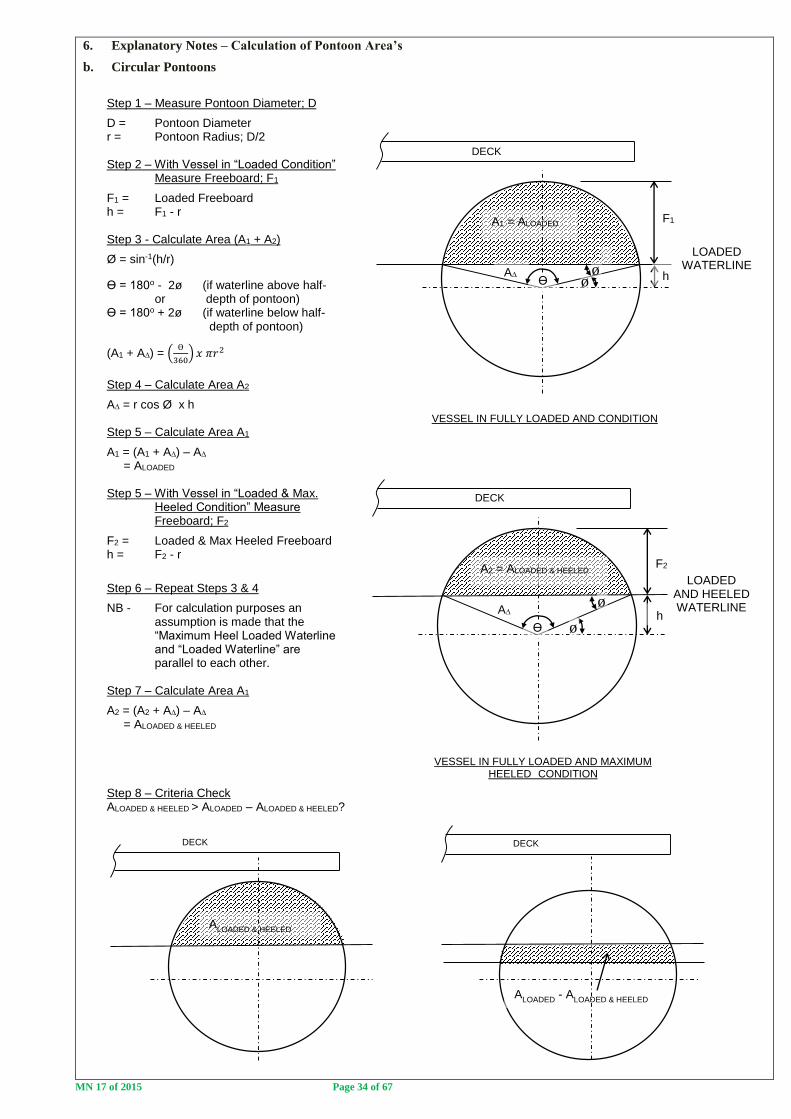
6. Explanatory Notes – Calculation of Pontoon Area’s
b. Circular Pontoons
DECK DECK
DECK
DECK
Step 1 – Measure Pontoon Diameter; D
D = Pontoon Diameter r = Pontoon Radius; D/2 Step 2 – With Vessel in “Loaded Condition” Measure Freeboard; F1
F1 = Loaded Freeboard h = F1 - r Step 3 - Calculate Area (A1 + A2)
Ø = sin-1(h/r)
Ө = 180o - 2ø (if waterline above half- or depth of pontoon) Ө = 180o + 2ø (if waterline below half- depth of pontoon)
(A1 + A∆) = (Ө
360) 𝑥 𝜋𝑟2
Step 4 – Calculate Area A2
A∆ = r cos Ø x h Step 5 – Calculate Area A1
A1 = (A1 + A∆) – A∆ = ALOADED Step 5 – With Vessel in “Loaded & Max. Heeled Condition” Measure Freeboard; F2
F2 = Loaded & Max Heeled Freeboard h = F2 - r
Step 6 – Repeat Steps 3 & 4
NB - For calculation purposes an assumption is made that the “Maximum Heel Loaded Waterline and “Loaded Waterline” are parallel to each other. Step 7 – Calculate Area A1
A2 = (A2 + A∆) – A∆ = ALOADED & HEELED Step 8 – Criteria Check ALOADED & HEELED > ALOADED – ALOADED & HEELED?
LOADED AND HEELED WATERLINE
F2
A∆
Ө ø
ø h
A2 = ALOADED & HEELED
VESSEL IN FULLY LOADED AND MAXIMUM HEELED CONDITION
LOADED WATERLINE
F1
A∆
A1 = ALOADED
Ө ø
h
VESSEL IN FULLY LOADED AND CONDITION
ø
ALOADED & HEELED
ALOADED
- ALOADED & HEELED

MN 17 of 2015 Page 35 of 67
7. Intact Stability – Maximum Heeling Moment (Longitudinal Stability)
Step 1 - With the vessel in an upright fully loaded condition, measure the freeboards at midships, Port and
Stbd (Transfer midship values from paragraph 2)
Step 2 - Transfer the weights or “passengers” forward in a controlled manner so that the weights or “passengers” are
congregated as far forward as is practicable. Measure the trimmed freeboards forward and aft (Port & Stbd)
Step 3 - Restore the weights/“passenger” to the initial condition (as in Step 1).
Step 4 - Repeat Step 2 but transferring the weights/”passengers” aft in a controlled manner so that the weights or
“passengers” are congregated as far aft as is practicable. Measure the trimmed freeboards forward and aft (Port &
Stbd)
Step 5 - Restore the weights/“passenger” to the initial condition (as in Step 1).
Step Description
Freeboard Measurements Forward or Aft section of
pontoon(s) submerged?
Yes/No
Freeboard
Aft [mm]
Freeboard
Fwd [mm]
Port Stbd Port Stbd
1 Initial Condition
2 Max. Trimming Moment - Fwd
3 Restore to Initial Condition
4 Max. Trimming Moment - Aft
5 Restore to Initial Condition
Description of weights/”passenger” shifted to achieve trimming moments with remarks (if any):
Criteria: a. With the vessel trimmed as far forward as is practicable as a
result of passenger crowding, the top of the forward pontoon
sections may not become submerged.
b. With the vessel trimmed as far aft as is practicable as a
result of passenger crowding, the top of the aft pontoon
sections may not become submerged.
DECK
INITIAL WATERLINE
MAXIMUM ALLOWABLE TRIM BY THE STERN AS A RESULT OF PASSENGER CROWDING
DECK
INITIAL WATERLINE
MAXIMUM ALLOWABLE TRIM BY BOW AS A RESULT OF PASSENGER CROWDING
PASS FAIL
PASS FAIL

MN 17 of 2015 Page 36 of 67
PART F - DAMAGED STABILITY
IMPORTANT
1. All passenger vessels are required to remain afloat, with positive transverse stability, when damaged ie. Not capsized.
All passenger vessels therefore need to demonstrate compliance with this part (practically or theoretically).
a. Vessel method of construction to survive damage (Tick Appropriate Box):
Built-in Buoyancy
Watertight Sub-division
Combination of Built-in Buoyancy & Watertight Sub-division
b. Confirmation of Compliance with Damaged Stability Criteria
Passenger vessels must be able to survive damage as follows:
i. Extent of Damage
Passenger vessels must be able to survive bottom or side damage of length; dL = 0.8 + 0.1L.
If the compartment lengths are greater than 0.8 + 0.1L then damage of the largest compartment is considered.
If the compartment lengths are less than 0.8 + 0.1L then damage of compartments as a result of damage of
length; dL = 0.8 + 0.1L must be considered.
The floodable volume (lost buoyancy) in compartments is therefore dependant on the compartment(s) size
and the amount of built-in buoyancy provided in the compartment(s).
ii. Minimum Survival Condition following damage:
Following a damage event with “Extent of Damage” being sustained, the vessel must remain upright
with positive transverse stability.
c. Owners have the option of proving compliance theoretically of practically; viz,
i. Theoretical compliance
It must be realised that the ingress of water into a compartment(s) results in changes to the vessel weight and
trim and may introduce free surface. Simplified calculations, illustrated in Part F2, may be carried out,
however, in the event of doubt and in any case if the water ingress as a result of damage will result in deck
edge immersion, is required that a theoretical calculation be carried out by a naval architect and submitted for
approval.
ii. Practical Compliance
A practical flooding test of the vessel may be carried out as follows:
Step 1 - The vessel must be initially loaded with all safety and operational equipment on board, including
crew and passengers. Fuel and water tanks must be between 75% and 100% full. Crew and passengers must
be located as for the vessels normal operation at the start of the test and may not be shifted to improve (or
worsen) the condition of the vessel during the practical test.
Step 2 - Determine the “Extent of Damage” for the vessel in accordance with paragraph 1(b)(i) and then
progressively flood the vessel, taking care not to create a capsize condition until an equilibrium point is
reached where the water level inside the compartment(s) is equal to the outside water level.
Criteria: In the damaged condition, the vessel must remain upright with positive transverse stability.
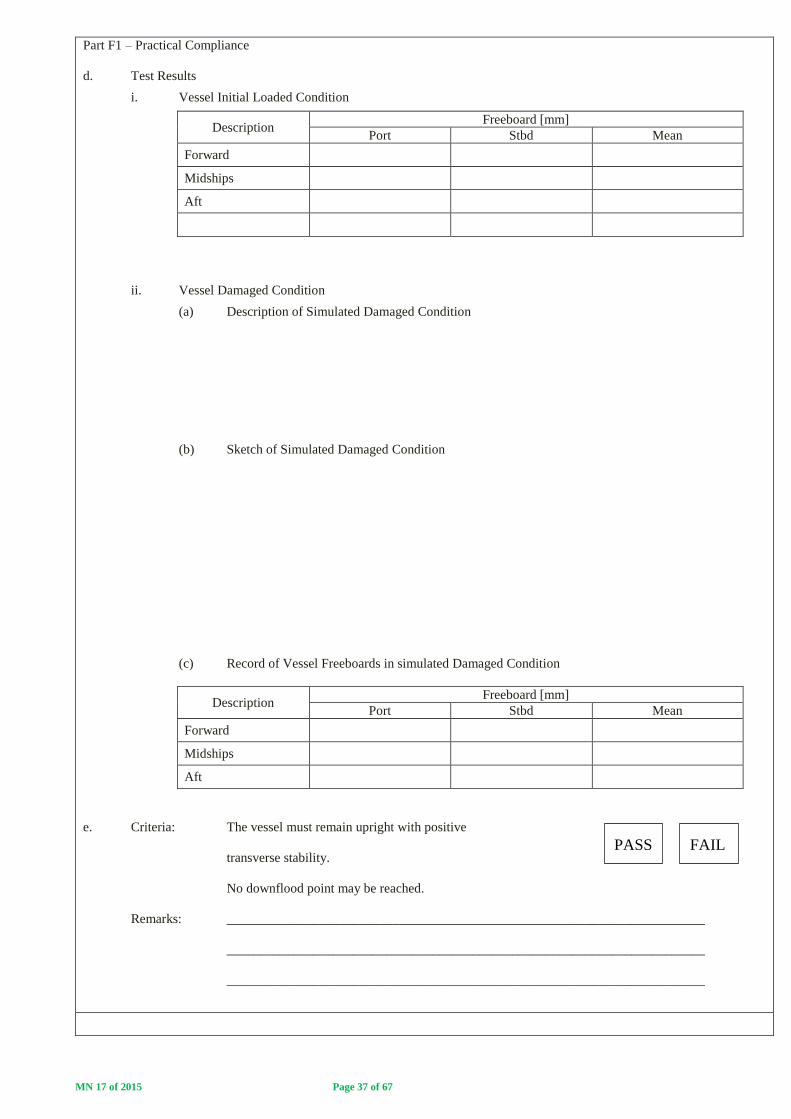
MN 17 of 2015 Page 37 of 67
Part F1 – Practical Compliance
d. Test Results
i. Vessel Initial Loaded Condition
Description Freeboard [mm]
Port Stbd Mean
Forward
Midships
Aft
ii. Vessel Damaged Condition
(a) Description of Simulated Damaged Condition
(b) Sketch of Simulated Damaged Condition
(c) Record of Vessel Freeboards in simulated Damaged Condition
Description Freeboard [mm]
Port Stbd Mean
Forward
Midships
Aft
e. Criteria: The vessel must remain upright with positive
transverse stability.
No downflood point may be reached.
Remarks: ________________________________________________________________________
________________________________________________________________________
________________________________________________________________________
PASS FAIL

MN 17 of 2015 Page 38 of 67
SMALL PASSENGER VESSEL
STABILITY RECORD FORM
OFFICIAL NUMBER:
AREA OF OPERATION:
MAXIMUM NUMBER OF PERSONS: # CREW + ## PASSENGERS
________________________________________ ____________________
PRINCIPAL OFFICER SIGNATURE DATE
INSERT PHOTO HERE

MN 17 of 2015 Page 39 of 67
SMALL PASSENGER VESSEL STABILITY RECORD FORM
GENERAL INFORMATION
This stability record form is used for recording the results of stability tests and calculations carried out to confirm that small
passenger vessels comply with the requirements of the Merchant Shipping (National Small Vessel Safety) Regulations, 2007
(NSVR).
Only SAMSA officers may carry out surveys of small passenger vessels for the issue of an appropriate Local General Safety
Certificate.
When correctly completed and signed by the attending SAMSA surveyor and approved by the Principal Officer of the region,
this stability record form demonstrates the vessels compliance with intact and damaged stability requirements of the NSVR.
Complete and approved forms must be retained with the vessels LGSC for reference of the owner and skipper and for presentation
at the time of survey and on the vessels file in SAMSA port offices.
APPLICATION
This form may only be used for the following small passenger vessel operations:
a. Category D or E vessel carrying not more than 20 passengers.
b. Category R vessel carrying not more than 30 passengers.
Notes:
- No passenger vessel may be operated more than 5 nm from shore and 15 nm from a safe haven.
The following parts of this form must be completed:
a. Monohull - Parts A, B, C, F
b. Multihull - Parts A, B, D, F
c. Pontoon Vessel - Parts A, B, E, F
NB - Part F relates to the vessels ability to survive reasonable damage ie. Damaged stability characteristics. The vessels
intact stability evaluation should not be carried out unless there is a clear understanding of how the vessels damaged stability
compliance will be demonstrated (See explanatory flow chart on the next page).
OPTIONS IN THE EVENT OF NON-COMPLIANCE
1. If the vessel design/configuration does not allow for measurements and evaluation to be carried out in accordance with
the instructions contained in each part, the test must be stopped and guidance requested from a SAMSA Naval Architect
before proceeding.
2. The procedures outlined for each part must be followed with all criteria required to be complied with. In the
event that criteria are not met, the owner should consider the following options:
a. Reduce the number of passengers/other weights until compliance is achieved.
b. Stop the test and approach a naval architect or professional engineer to carry out more detailed theoretical
calculations or to model the vessel hull and conduct a full stability evaluation.

MN 17 of 2015 Page 40 of 67
FLOW CHART FOR STABILITY EVALUATION PROCESS
YES YES
YES YES
YES
NO NO
NO NO
NO
TO BE CONFIRMED BY HYDROSTATIC MODELLING
TO BE CONFIRMED PRACTICALLY
TO BE CONFIRMED THEORETICALLY
PRACTICAL / THEORETICAL STABILITY EVALUATION FOR ISSUE OF A SMALL PASSENGER
VESSELSTABILITY RECORD FORM
DAMAGE STABILITY
SURVIVABILITY CONFIRMATION
OWNER TO PRESENT THEORETICAL CALCULATIONS OR SURVEYOR TO SATISFY HIMSELF/HERSELF THAT THE VESSEL WILL REMAIN AFLOAT WITH POSITIVE TRANSVERSE STABILITY IN THE EVENT OF DAMAGE (EXTENT OF DAMAGE; dL = 0.8 + 0.1L) AS A RESULT OF THE VESSELS SURVIVABILITY PROVISIONS; VIZ, - BUILT-IN BUOYANCY - WATERTIGHT SUB-DIVISION
CONDUCT PRACTICAL INTACT
STABILITY EVALUATION
COMPLETE INTACT STABILITY SECTIONS OF SMALL PASSENGER VESSEL RECORD FORM (SIGNED BY SURVEYOR). COMPLETE THEORETICAL DAMAGE STABILITY SECTION OF STABILITY RECORD FORM (SUPPLEMENTED WITH OWNER CALCULATIONS, IF APPLICABLE)
COMPLETE SMALL PASSENGER VESSEL STABILITY RECORD FORM (SIGNED BY BY SURVEYOR AND APPROVED BY PRINCIPAL OFFICER
ISSUE TO OWNER (TO BE RETAINED ON BOARD WITH LOCAL GENERAL SAFETY (SAMSA COPY TO BE RETAINED ON FILE)
CONDUCT PRACTICAL INTACT STABILITY EVALUATION
CORRECTIVE ACTION Eg.REDUCE PAX No’s
CORRECTIVE ACTION Eg.REDUCE PAX No’s
CONDUCT PRACTICAL DAMAGE STABILITY
EVALUATION
CORRECTIVE ACTION
NAVAL ARCHITECT TO MODEL VESSEL AND PROVE
INTACT AND DAMAGED STABILITY COMPLIANCE. STABILITY STATEMENT
GENERATED
SUBMIT TO SAMSA NAVAL ARCHITECT
FOR APPROVAL
CORRECTIVE ACTION
STABILITY STATEMENT APPROVED BY SAMSA NAVAL ARCHITECT
SATISFACTORY ?
SATISFACTORY ?
SATISFACTORY
?
SATISFACTORY ?
SATISFACTORY ?

MN 17 of 2015 Page 41 of 67
PART A - GENERAL PARTICULARS
Name of Vessel: _______________________________ Off No. ______________________________
Owner/Representative: _______________________________ Date: ______________________________
SAMSA Surveyor(s): _______________________________
_______________________________ Weather Conditions
Location: _______________________________ Wind: ________________________
Water: ________________________
Description of Vessel Operation:
________________________________________________________________________________________________
________________________________________________________________________________________________
________________________________________________________________________________________________
________________________________________________________________________________________________
Application:
This record form is for the following small passenger vessel operations (Mark the relevant box):
Category D or E vessel carrying not more than 20 passengers.
Category R vessel carrying not more than 30 passengers.
This record is or the following vessel type (Mark the relevant box):
Monohull - Parts A, B, C & F completed.
Multihull - Parts A, B, D & F completed.
Pontoon Vessel - Parts A, B, E & F completed.
Surveyor Remarks:
_________________________________________________________________________________________
_________________________________________________________________________________________
_________________________________________________________________________________________
_________________________________________________________________________________________
_________________________________________________________________________________________
_________________________________________________________________________________________

MN 17 of 2015 Page 42 of 67
PART B – VESSEL PREPARATION AND PREVAILING WEATHER CONDITIONS
The vessel must be prepared and presented for practical stability evaluation as follows:
Initial Vessel Condition:
- The vessel must be in a complete condition ie. Not still under construction.
- The vessel must upright and moored alongside with slack mooring lines.
- The vessel hull(s) must be confirmed free of water.
Vessel Loaded Condition:
The vessel must be initially loaded with all safety and operational equipment on board, excluding crew and passengers. Fuel
and water tanks must be between 75% and 100% full.
Persons or weights may be used to represent the crew and passenger load (Persons/weights must be prepared and ready for use
as required by the attending surveyor).
In the event of weights being utilised, each “passenger/crew” shall be represented by a weight of 82.5 kg.
Standing passengers shall be assumed to congregate at 0.25 m2 per person and their vertical centre of gravity shall be assumed
to be 1.0m above the deck.
Seated passengers shall be provided with a minimum seat spacing of 500mm and their vertical centre of gravity shall be
assumed to be 0.3m above the seat.
In the event of persons being used as “passengers/crew”, the principles outlined above should be applied when distributing
persons in the course of the tests.
Weather Conditions:
The prevailing weather conditions must allow for the required tests to be carried out in a safe and controlled manner and for
freeboard measurements to be accurately taken.
Surveyor Confirmation:
The vessel condition and prevailing weather conditions are considered satisfactory for the conduct of the requisite
testing.
Remarks: _______________________________________________________________________
_______________________________________________________________________
_______________________________________________________________________
_______________________________________________________________________
_______________________________________________________________________
_______________________________________________________________________
_______________________________________________________________________
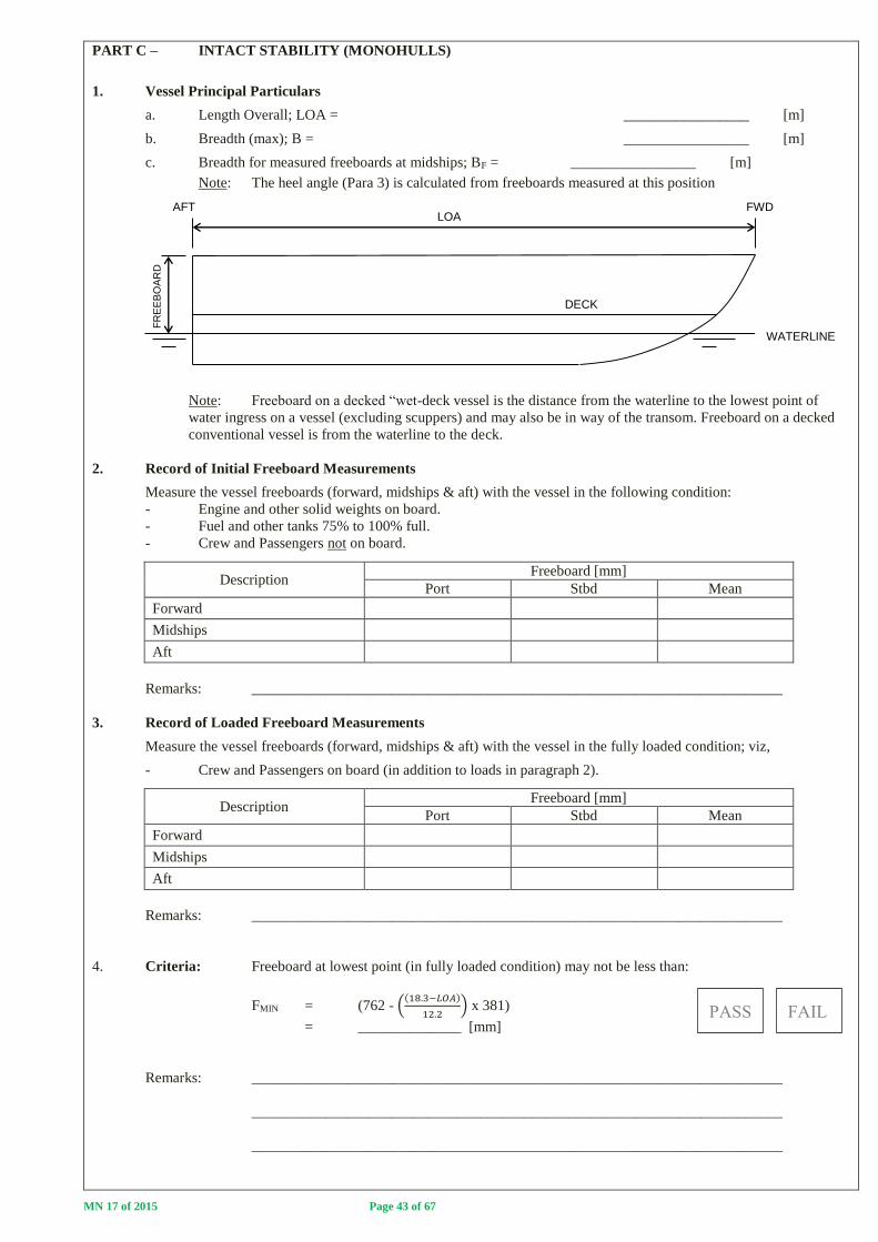
MN 17 of 2015 Page 43 of 67
PART C – INTACT STABILITY (MONOHULLS)
1. Vessel Principal Particulars
a. Length Overall; LOA = _________________ [m]
b. Breadth (max); B = _________________ [m]
c. Breadth for measured freeboards at midships; BF = _________________ [m]
Note: The heel angle (Para 3) is calculated from freeboards measured at this position
Note: Freeboard on a decked “wet-deck vessel is the distance from the waterline to the lowest point of
water ingress on a vessel (excluding scuppers) and may also be in way of the transom. Freeboard on a decked
conventional vessel is from the waterline to the deck.
2. Record of Initial Freeboard Measurements
Measure the vessel freeboards (forward, midships & aft) with the vessel in the following condition:
- Engine and other solid weights on board.
- Fuel and other tanks 75% to 100% full.
- Crew and Passengers not on board.
Description Freeboard [mm]
Port Stbd Mean
Forward
Midships
Aft
Remarks: ________________________________________________________________________
3. Record of Loaded Freeboard Measurements
Measure the vessel freeboards (forward, midships & aft) with the vessel in the fully loaded condition; viz,
- Crew and Passengers on board (in addition to loads in paragraph 2).
Description Freeboard [mm]
Port Stbd Mean
Forward
Midships
Aft
Remarks: ________________________________________________________________________
4. Criteria: Freeboard at lowest point (in fully loaded condition) may not be less than:
FMIN = (762 - ((18.3−𝐿𝑂𝐴)
12.2) x 381)
= ______________ [mm]
Remarks: ________________________________________________________________________
________________________________________________________________________
________________________________________________________________________
DECK
FR
EE
BO
AR
D
LOA
WATERLINE
AFT FWD

MN 17 of 2015 Page 44 of 67
5. Intact Stability – Maximum Heeling Moment
Step 1 - With the vessel in an upright fully loaded condition, measure the freeboards at midships, Port and
Stbd (Transfer midship values from paragraph 2)
Step 2 - Transfer the weights or “passengers” in a controlled manner from Port to Stbd so that 75% of the passengers
are on the Stbd Side and 25% remain on the Port Side. Measure and record the freeboards at midships and
calculate the heel angle.
Criteria: Heel angle less than 7 degrees and deck edge immersion may not occur.
Heel Angle; Ө = tan-1 (Freeboard Port – Freeboard Stbd)/BF
Step 3 - Transfer the remainder of the weights/“passengers” to the Stbd Side so that the maximum practical
heeling moment to Stbd is created. Measure and record the freeboards at midships.
Criteria: Capsizing moment may not be introduced nor may a downflood point(s) be reached.
Step 4 - Restore the weights/“passenger” to the initial condition (as in Step 1).
Step 5 - Repeat Step 2 but transferring the weights/”passengers” from Stbd to Port.
Step 6 - Repeat Step 2 but transferring the weights/”passengers” from Stbd to Port.
Step 7 - Restore the weights/“passenger” to the initial condition (as in Step 1).
Step Description
Freeboard Measurement at
Midships [mm]
Heel
Angle
[degrees]
Deck Edge
Immersion?
Yes/No
Downflood Point
reached? Yes/No
Port Stbd
1 Initial Condition
2 75/25 Heeling Moment (Stbd)
3 Maximum Heeling Moment
4 Restore to Initial Condition
5 75/25 Heeling Moment (Port)
6 Maximum Heeling Moment
7 Restore to Initial Condition
Description of weights/”passenger” shifted to achieve heeling moments with remarks (if any):
____________________________________________________________________________________
____________________________________________________________________________________
Downflooding point - An opening through which progressive flooding of a hull will take place which is not able to to be
closed watertight. On decked vessels (see sketch above), downflood points are openings in the hull which lead to below deck
space(s). On undecked vessels, the down-flood point is the lowest point on the hull which will lead to water ingress into the
vessel.
Criteria: a. For 75/25 applied heeling moment; resultant heel angle
less than 7 degrees and no deck edge immersion.
b. For maximum applied heeling moment; capsizing moment
not introduced and no downflood point reached.
Remarks: ________________________________________________________________________
________________________________________________________________________
Ө
FR
EE
BO
AR
D
BF
DECK
LOADED WATERLINE
DOWNFLOOD POINT
HEELED WATERLINE

MN 17 of 2015 Page 45 of 67
PART D – INTACT STABILITY (MULTIHULLS)
1. Vessel Principal Particulars
a. Length Overall; LOA = _________________ [m]
b. Breadth (max); B = _________________ [m]
c. Breadth for measured freeboards at midships; BF = _________________ [m]
Note: The heel angle (Para 3) is calculated from freeboards measured at this position
Note: Freeboard on a decked “wet-deck vessel is the distance from the waterline to the lowest point of
water ingress on a vessel (excluding scuppers) and may also be in way of the transom. Freeboard on a decked
conventional vessel is from the waterline to the deck.
2. Record of Initial Freeboard Measurements
Measure the vessel freeboards (forward, midships & aft) with the vessel in the following condition:
- Engine and other solid weights on board.
- Fuel and other tanks 75% to 100% full.
- Crew and Passengers not on board.
Description Freeboard [mm]
Port Stbd Mean
Forward
Midships
Aft
Remarks: ________________________________________________________________________
3. Record of Loaded Freeboard Measurements
Measure the vessel freeboards (forward, midships & aft) with the vessel in the fully loaded condition; viz,
- Crew and Passengers on board (in addition to loads in paragraph 2).
Description Freeboard [mm]
Port Stbd Mean
Forward
Midships
Aft
Remarks: ________________________________________________________________________
4. Criteria: Freeboard at lowest point (in fully loaded condition) may not be less than:
FMIN = (762 - ((18.3−𝐿𝑂𝐴)
12.2) x 381)
= ______________ [mm]
Remarks: ________________________________________________________________________
________________________________________________________________________
________________________________________________________________________
DECK
FR
EE
BO
AR
D
LOA
WATERLINE
AFT FWD

MN 17 of 2015 Page 46 of 67
5. Intact Stability – Maximum Heeling Moment
Step 1 - With the vessel in an upright fully loaded condition, measure the freeboards at midships, Port and
Stbd (Transfer midship values from paragraph 2)
Step 2 - Transfer the weights or “passengers” in a controlled manner from Port to Stbd so that 75% of the
passengers are on the Stbd Side and 25% remain on the Port Side. Measure and record the
freeboards at midships and calculate the heel angle.
Criteria: Heel angle less than 7 degrees and deck edge immersion may not occur.
Heel Angle; Ө = tan-1 (Freeboard Port – Freeboard Stbd)/BF
Step 3 - Transfer the remainder of the weights/“passengers” to the Stbd Side so that the maximum practical
heeling moment to Stbd is created. Measure and record the freeboards at midships.
Criteria: Capsizing moment may not be introduced nor may a downflood point(s) be reached.
Step 4 - Restore the weights/“passenger” to the initial condition (as in Step 1).
Step 5 - Repeat Step 2 but transferring the weights/”passengers” from Stbd to Port.
Step 6 - Repeat Step 2 but transferring the weights/”passengers” from Stbd to Port.
Step 7 - Restore the weights/“passenger” to the initial condition (as in Step 1).
Step Description
Freeboard Measurement at
Midships [mm]
Heel
Angle
[degrees]
Deck Edge
Immersion?
Yes/No
Downflood Point
reached? Yes/No
Port Stbd
1 Initial Condition
2 75/25 Heeling Moment (Stbd)
3 Maximum Heeling Moment
4 Restore to Initial Condition
5 75/25 Heeling Moment (Port)
6 Maximum Heeling Moment
7 Restore to Initial Condition
Description of weights/”passenger” shifted to achieve heeling moments with remarks (if any):
____________________________________________________________________________________
____________________________________________________________________________________
Downflooding point - An opening through which progressive flooding of a hull will take place which is not able to
to be closed watertight. On decked vessels (see sketch above), downflood points are
openings in the hull which lead to below deck space(s). On undecked vessels, the down-
flood point is the lowest point on the hull which will lead to water ingress into the vessel.
Criteria: a. For 75/25 applied heeling moment; resultant heel angle
less than 7 degrees and no deck edge immersion.
b. For maximum applied heeling moment; capsizing moment
not introduced and no downflood point reached.
Remarks: ________________________________________________________________________
________________________________________________________________________
Ө
FR
EE
BO
AR
D
BF
DECK
LOADED WATERLINE
DOWNFLOOD POINT
HEELED WATERLINE

MN 17 of 2015 Page 47 of 67
PART E – INTACT STABILITY (PONTOON VESSELS)
NB – ONLY APPLICABLE TO CATEGORY R VESSELS
1. Vessel Principal Particulars
a. Length Overall; LOA = _________________ [m]
b. Breadth (max); B = _________________ [m]
c. Breadth for measured freeboards at midships; BF = _________________ [m]
Note: The heel angle (Para 3) is calculated from freeboards measured at this position
Note: Freeboard is the vertical distance measured from the top of the pontoon to the waterline (Not from the top of
the deck).
2. Record of Initial Freeboard Measurements
Measure the vessel freeboards (forward, midships & aft) with the vessel in the following condition:
- Engine and other solid weights on board.
- Fuel and other tanks 75% to 100% full.
- Crew and Passengers not on board.
Description Freeboard [mm]
Port Stbd Mean
Forward
Midships
Aft
Remarks: ________________________________________________________________________
3. Record of Loaded Freeboard Measurements
Measure the vessel freeboards (forward, midships & aft) with the vessel in the fully loaded condition; viz,
- Crew and Passengers on board (in addition to loads in paragraph 2).
Description Freeboard [mm]
Port Stbd Mean
Forward
Midships
Aft
Remarks: ________________________________________________________________________
4. Criteria: Freeboard at lowest point (in fully loaded condition) may not be less than:
FMIN = (762 - ((18.3−𝐿𝑂𝐴)
12.2) x 381)
= ______________ [mm]
Remarks: ________________________________________________________________________
________________________________________________________________________
________________________________________________________________________
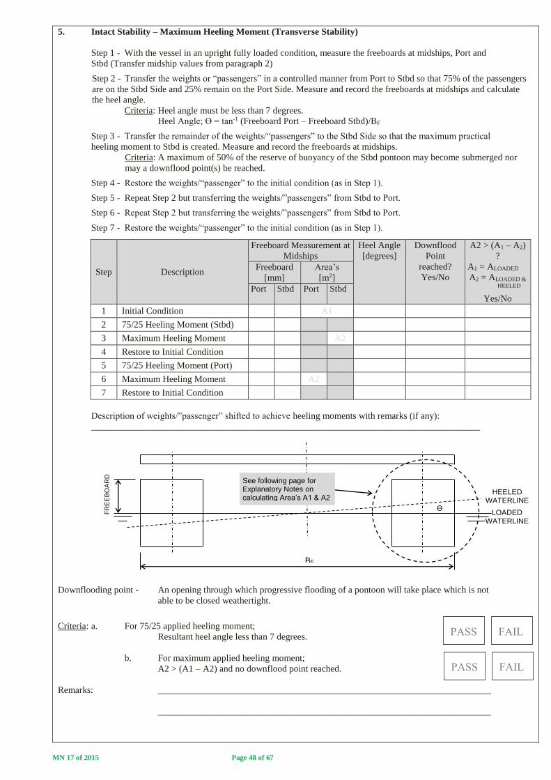
MN 17 of 2015 Page 48 of 67
5. Intact Stability – Maximum Heeling Moment (Transverse Stability)
Step 1 - With the vessel in an upright fully loaded condition, measure the freeboards at midships, Port and
Stbd (Transfer midship values from paragraph 2)
Step 2 - Transfer the weights or “passengers” in a controlled manner from Port to Stbd so that 75% of the passengers
are on the Stbd Side and 25% remain on the Port Side. Measure and record the freeboards at midships and calculate
the heel angle.
Criteria: Heel angle must be less than 7 degrees.
Heel Angle; Ө = tan-1 (Freeboard Port – Freeboard Stbd)/BF
Step 3 - Transfer the remainder of the weights/“passengers” to the Stbd Side so that the maximum practical
heeling moment to Stbd is created. Measure and record the freeboards at midships.
Criteria: A maximum of 50% of the reserve of buoyancy of the Stbd pontoon may become submerged nor
may a downflood point(s) be reached.
Step 4 - Restore the weights/“passenger” to the initial condition (as in Step 1).
Step 5 - Repeat Step 2 but transferring the weights/”passengers” from Stbd to Port.
Step 6 - Repeat Step 2 but transferring the weights/”passengers” from Stbd to Port.
Step 7 - Restore the weights/“passenger” to the initial condition (as in Step 1).
Step Description
Freeboard Measurement at
Midships
Heel Angle
[degrees]
Downflood
Point
reached?
Yes/No
A2 > (A1 – A2)
?
A1 = ALOADED
A2 = ALOADED & HEELED
Yes/No
Freeboard
[mm]
Area’s
[m2]
Port Stbd Port Stbd
1 Initial Condition A1
2 75/25 Heeling Moment (Stbd)
3 Maximum Heeling Moment A2
4 Restore to Initial Condition
5 75/25 Heeling Moment (Port)
6 Maximum Heeling Moment A2
7 Restore to Initial Condition
Description of weights/”passenger” shifted to achieve heeling moments with remarks (if any):
____________________________________________________________________________________
Downflooding point - An opening through which progressive flooding of a pontoon will take place which is not
able to be closed weathertight.
Criteria: a. For 75/25 applied heeling moment;
Resultant heel angle less than 7 degrees.
b. For maximum applied heeling moment;
A2 > (A1 – A2) and no downflood point reached.
Remarks: ________________________________________________________________________
________________________________________________________________________
BF
LOADED WATERLINE
Ө
FR
EE
BO
AR
D
HEELED WATERLINE
See following page for Explanatory Notes on calculating Area’s A1 & A2

MN 17 of 2015 Page 49 of 67
6. Explanatory Notes – Calculation of Pontoon Area’s
a. Rectangular Pontoons
DECK DECK
DECK
DECK Step 1 – Measure Pontoon Breadth; B
B = Pontoon Breadth Step 2 – With Vessel in “Loaded Condition” Measure Freeboard; F1
F1 = Loaded Freeboard Step 3 - Calculate Area A1
A1 = B x F1 Step 4 – With Vessel in “Loaded & Max Heeled Condition” Measure Freeboard; F2
F2 = Loaded & Max. Heeled Freeboard Step 5 - Calculate Area A2
A2 = B x F2 NB - For calculation purposes an assumption is made that the “Maximum Heel Loaded Waterline and “Loaded Waterline” are parallel to each other. Step 8 – Criteria Check Confirm A2 > A1 – A2
LOADED WATERLINE
LOADED WATERLINE
LOADED & HEELED
WATERLINE
VESSEL IN FULLY LOADED CONDITION
VESSEL IN FULLY LOADED AND MAXIMUM HEELED CONDITION
F1
B
A1 = A
LOADED
F1
B
F2
A2 = A
LOADED & HEELED
A2
A1 – A2

MN 17 of 2015 Page 50 of 67
b. Circular Pontoons
DECK DECK
DECK
DECK
Step 1 – Measure Pontoon Diameter; D
D = Pontoon Diameter r = Pontoon Radius; D/2 Step 2 – With Vessel in “Loaded Condition” Measure Freeboard; F1
F1 = Loaded Freeboard h = F1 - r Step 3 - Calculate Area (A1 + A2)
Ø = sin-1(h/r)
Ө = 180o - 2ø (if waterline above half- or depth of pontoon) Ө = 180o + 2ø (if waterline below half- depth of pontoon)
(A1 + A∆) = (Ө
360) 𝑥 𝜋𝑟2
Step 4 – Calculate Area A2
A∆ = r cos Ø x h Step 5 – Calculate Area A1
A1 = (A1 + A∆) – A∆ = ALOADED Step 5 – With Vessel in “Loaded & Max. Heeled Condition” Measure Freeboard; F2
F2 = Loaded & Max Heeled Freeboard h = F2 - r
Step 6 – Repeat Steps 3 & 4
NB - For calculation purposes an assumption is made that the “Maximum Heel Loaded Waterline and “Loaded Waterline” are parallel to each other. Step 7 – Calculate Area A1
A2 = (A2 + A∆) – A∆ = ALOADED & HEELED Step 8 – Criteria Check ALOADED & HEELED > ALOADED – ALOADED & HEELED?
LOADED AND HEELED WATERLINE
F2
A∆
Ө ø
ø h
A2 = ALOADED & HEELED
VESSEL IN FULLY LOADED AND MAXIMUM HEELED CONDITION
LOADED WATERLINE
F1
A∆
A1 = ALOADED
Ө ø
h
VESSEL IN FULLY LOADED AND CONDITION
ø
ALOADED & HEELED
ALOADED
- ALOADED & HEELED
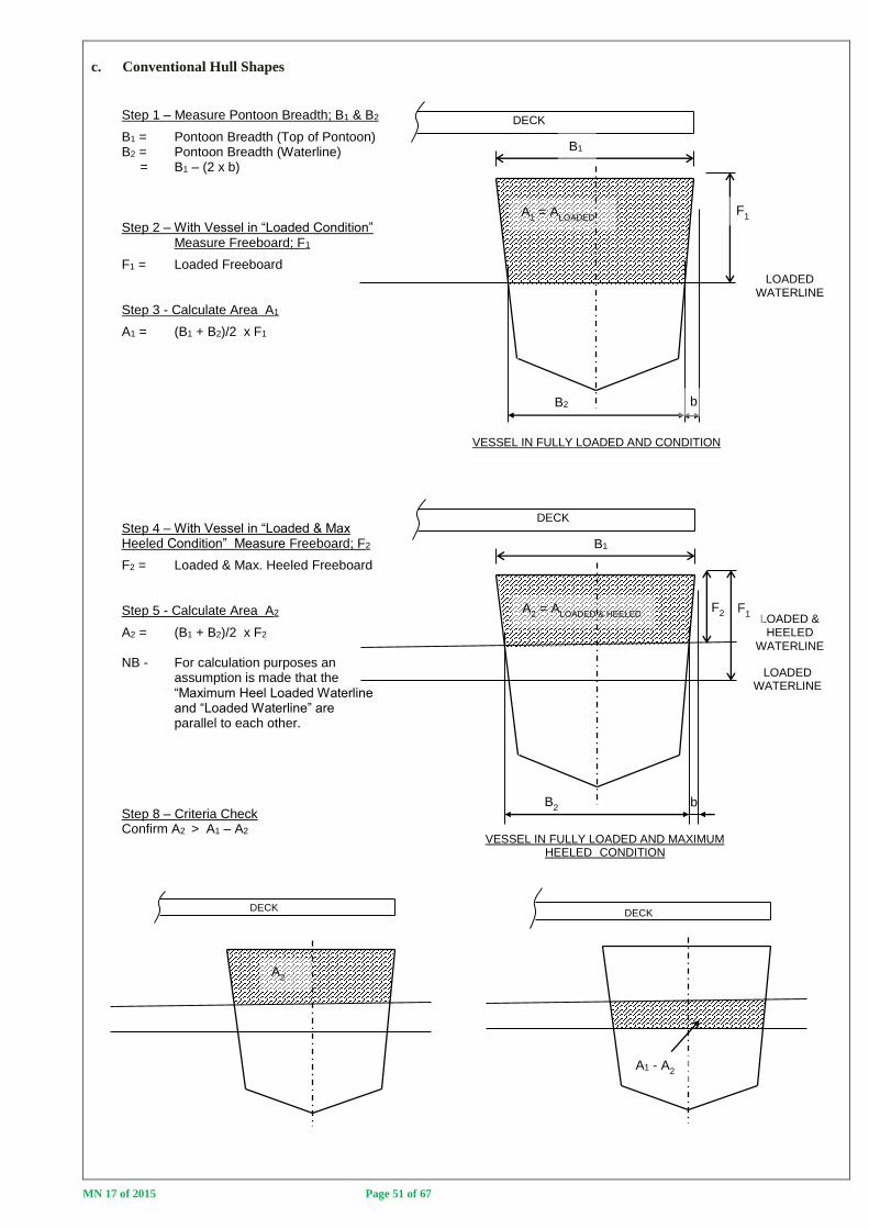
MN 17 of 2015 Page 51 of 67
c. Conventional Hull Shapes
DECK
DECK
DECK DECK
Step 1 – Measure Pontoon Breadth; B1 & B2
B1 = Pontoon Breadth (Top of Pontoon) B2 = Pontoon Breadth (Waterline) = B1 – (2 x b) Step 2 – With Vessel in “Loaded Condition” Measure Freeboard; F1
F1 = Loaded Freeboard Step 3 - Calculate Area A1
A1 = (B1 + B2)/2 x F1 Step 4 – With Vessel in “Loaded & Max Heeled Condition” Measure Freeboard; F2
F2 = Loaded & Max. Heeled Freeboard Step 5 - Calculate Area A2
A2 = (B1 + B2)/2 x F2 NB - For calculation purposes an assumption is made that the “Maximum Heel Loaded Waterline and “Loaded Waterline” are parallel to each other. Step 8 – Criteria Check Confirm A2 > A1 – A2
LOADED WATERLINE
LOADED WATERLINE
LOADED & HEELED
WATERLINE
VESSEL IN FULLY LOADED AND CONDITION
VESSEL IN FULLY LOADED AND MAXIMUM HEELED CONDITION
B2
F1
B1
A1 = A
LOADED
b
B2 b
F1
B1
F2
A2 = A
LOADED & HEELED
A2
A1 - A2

MN 17 of 2015 Page 52 of 67
7. Intact Stability – Maximum Heeling Moment (Longitudinal Stability)
Step 1 - With the vessel in an upright fully loaded condition, measure the freeboards at midships, Port and
Stbd (Transfer midship values from paragraph 2)
Step 2 - Transfer the weights or “passengers” forward in a controlled manner so that the weights or “passengers” are
congregated as far forward as is practicable. Measure the trimmed freeboards forward and aft (Port & Stbd)
Step 3 - Restore the weights/“passenger” to the initial condition (as in Step 1).
Step 4 - Repeat Step 2 but transferring the weights/”passengers” aft in a controlled manner so that the weights or
“passengers” are congregated as far aft as is practicable. Measure the trimmed freeboards forward and aft (Port &
Stbd)
Step 5 - Restore the weights/“passenger” to the initial condition (as in Step 1).
Step Description
Freeboard Measurements Forward or Aft section of
pontoon(s) submerged?
Yes/No
Freeboard
Aft [mm]
Freeboard
Fwd [mm]
Port Stbd Port Stbd
1 Initial Condition
2 Max. Trimming Moment - Fwd
3 Restore to Initial Condition
4 Max. Trimming Moment - Aft
5 Restore to Initial Condition
Description of weights/”passenger” shifted to achieve trimming moments with remarks (if any):
____________________________________________________________________________________
____________________________________________________________________________________
Criteria: a. With the vessel trimmed as far forward as is practicable as a
result of passenger crowding, the top of the forward pontoon
sections may not become submerged.
b. With the vessel trimmed as far aft as is practicable as a
result of passenger crowding, the top of the aft pontoon
sections may not become submerged.
DECK
INITIAL WATERLINE
MAXIMUM ALLOWABLE TRIM BY THE STERN AS A RESULT OF PASSENGER CROWDING
DECK
INITIAL WATERLINE
MAXIMUM ALLOWABLE TRIM BY BOW AS A RESULT OF PASSENGER CROWDING

MN 17 of 2015 Page 53 of 67
PART F - DAMAGED STABILITY
IMPORTANT
1. All passenger vessels are required to remain afloat, with positive transverse stability, when damaged ie. not capsized.
All passenger vessels therefore need to demonstrate compliance with this part (practically or theoretically).
a. Vessel method of construction to survive damage (Tick Appropriate Box):
Built-in Buoyancy
Watertight Sub-division
Combination of Built-in Buoyancy & Watertight Sub-division
b. Confirmation of Compliance with Damaged Stability Criteria
Passenger vessels must be able to survive damage as follows:
i. Extent of Damage
Passenger vessels must be able to survive bottom or side damage of length; dL = 0.8 + 0.1L.
If the compartment lengths are greater than 0.8 + 0.1L then damage of the largest compartment isconsidered.
If the compartment lengths are less than 0.8 + 0.1L then damage of compartments as a result of damage of
length; dL = 0.8 + 0.1L must be considered.
The floodable volume (lost buoyancy) in compartments is therefore dependant on the compartment(s) size
and the amount of built-in buoyancy provided in the compartment(s).
ii. Minimum Survival Condition following damage:
Following a damage event with “Extent of Damage” being sustained, the vessel must remain upright
with positive transverse stability.
c. Owners have the option of proving compliance theoretically of practically; viz,
i. Theoretical compliance
It must be realised that the ingress of water into a compartment(s) results in changes to the vessel weight and
trim and may introduce free surface. Simplified calculations, illustrated in Part F2, may be carried out,
however, in the event of doubt and in any case if the water ingress as a result of damage will result in deck
edge immersion, is required that a theoretical calculation be carried out by a naval architect and submitted for
approval.
ii. Practical Compliance
A practical flooding test of the vessel may be carried out as follows:
Step 1 - The vessel must be initially loaded with all safety and operational equipment on board, including
crew and passengers. Fuel and water tanks must be between 75% and 100% full. Crew and passengers must
be located as for the vessels normal operation at the start of the test and may not be shifted to improve (or
worsen) the condition of the vessel during the practical test.
Step 2 - Determine the “Extent of Damage” for the vessel in accordance with paragraph 1(b)(i) and then
progressively flood the vessel, taking care not to create a capsize condition until an equilibrium point is
reached where the water level inside the compartment(s) is equal to the outside water level.
Criteria: In the damaged condition, the vessel must remain upright with positive transverse stability.
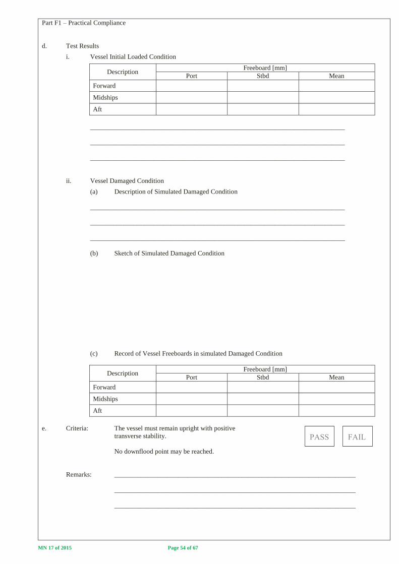
MN 17 of 2015 Page 54 of 67
Part F1 – Practical Compliance
d. Test Results
i. Vessel Initial Loaded Condition
Description Freeboard [mm]
Port Stbd Mean
Forward
Midships
Aft
____________________________________________________________________________
____________________________________________________________________________
____________________________________________________________________________
ii. Vessel Damaged Condition
(a) Description of Simulated Damaged Condition
____________________________________________________________________________
____________________________________________________________________________
____________________________________________________________________________
(b) Sketch of Simulated Damaged Condition
(c) Record of Vessel Freeboards in simulated Damaged Condition
Description Freeboard [mm]
Port Stbd Mean
Forward
Midships
Aft
e. Criteria: The vessel must remain upright with positive
transverse stability.
No downflood point may be reached.
Remarks: ________________________________________________________________________
________________________________________________________________________
________________________________________________________________________

MN 17 of 2015 Page 55 of 67
Part F2 – Theoretical Compliance (Use additional pages as required)
Part F2a - Pontoon Vessels
With reference to the above sketch; List the following vessel particulars:
a. Deck Length ___________________________ [m]
b. Breadth ___________________________ [m]
c. Depth ___________________________ [m]
STEP 1 - CALCULATION OF VESSEL WEIGHT
Vessel weight = Lightweight + Deadweight . . . . . . (1)
The vessel weight may either be obtained by weighing the boat or by Archimedes Principle
ie.Weight of Boat = Weight of Water Displaced by Boat
If the weight of the boat is obtained by weighing, complete table 1 below:
Description Weight [kg]
Weight of Boat (as weighed)
Less Engine weight(s)
Less Miscellaneous weights
Therefore; Lightweight of boat =
Table 1
D
B L
WATERLINE

MN 17 of 2015 Page 56 of 67
If the vessel lightweight is to be calculated from Archimedes Principle:
MW = VW = AUNDERWATER HULL SECTIONS x LWATERLINE . . . . . (2)
Using basic geometry equations calculate the weight of the pontoon vessel using equation (2) in the space below and
then complete Table 1.
WATERLINE
D
B LWATERLINE =
Freeboard, F
Draught, T
- UNDERWATER HULL SECTIONS
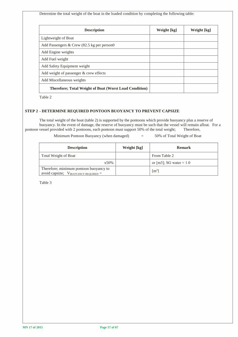
MN 17 of 2015 Page 57 of 67
Determine the total weight of the boat in the loaded condition by completing the following table:
Description Weight [kg] Weight [kg]
Lightweight of Boat
Add Passengers & Crew (82.5 kg per person0
Add Engine weights
Add Fuel weight
Add Safety Equipment weight
Add weight of passenger & crew effects
Add Miscellaneous weights
Therefore; Total Weight of Boat (Worst Load Condition)
Table 2
STEP 2 - DETERMINE REQUIRED PONTOON BUOYANCY TO PREVENT CAPSIZE
The total weight of the boat (table 2) is supported by the pontoons which provide buoyancy plus a reserve of
buoyancy. In the event of damage, the reserve of buoyancy must be such that the vessel will remain afloat. For a
pontoon vessel provided with 2 pontoons, each pontoon must support 50% of the total weight; Therefore,
Minimum Pontoon Buoyancy (when damaged) = 50% of Total Weight of Boat
Description Weight [kg] Remark
Total Weight of Boat From Table 2
x50% or [m3]; SG water ≈ 1.0
Therefore; minimum pontoon buoyancy to
avoid capsize; VBUOYANCY REQUIRED =
[m3]
Table 3

MN 17 of 2015 Page 58 of 67
STEP 3 – CALCULATE PONTOON BUOYANCY FOLLOWING DAMAGE
Extent of Damage = 0.8 + 0.1 L = _________________ [m]
Sketch the pontoon vessel configuration and resultant flooding as a result of damage = “Extent of Damage”
Calculate the Buoyancy in the Damaged Pontoon; VBUOYANCY DAMAGED
_____________________________________________________________________________________
_____________________________________________________________________________________
_____________________________________________________________________________________
_____________________________________________________________________________________
_____________________________________________________________________________________
_____________________________________________________________________________________
_____________________________________________________________________________________
Therefore: VBUOYANCY DAMAGED = _________ [m3]
STEP 4 - CONFIRM BUOYANCY IN DAMAGED PONTOON SUFFICIENT TO AVOID CAPSIZE
VBUOYANCY REQUIRED = ______________ [m3] From Table 3
VBUOYANCY DAMAGED = ______________ [m3]
If VBUOYANCY DAMAGED > VBUOYANCY REQUIRED then vessel will remain afloat and not capsize.
REMARKS:
____________________________________________________________________________________
____________________________________________________________________________________
____________________________________________________________________________________

MN 17 of 2015 Page 59 of 67
Part F2 – Theoretical Compliance (Use additional pages as required)
Part F2b - Monohulls
Notes 1. Theoretical calculations may only be carried out by surveyors if the vessel is provided with
built-in buoyancy. In the event of the vessel being provided with watertight sub-divisions, the owner must
either prove compliance practically ormake use of the services of a naval architect to prove theoretical
compliance.
2. If the below deck volume is filled with built-in buoyancy with 100% permeability eg.
closed cell polyurethane foam and the vessel deck is above the waterline in the fully loaded condition, then it
is not necessary to carry out a theoretical damaged stability calculation as no water ingress into the hull will
take place in the event of damage.
With reference to the above sketch; List the following vessel particulars:
a. Deck Length ___________________________ [m]
b. Breadth ___________________________ [m]
c. Depth ___________________________ [m]
STEP 1 - CALCULATION OF VESSEL WEIGHT
Vessel weight = Lightweight + Deadweight . . . . . . (1)
The vessel weight may either be obtained by weighing the boat or by Archimedes Principle
ie.Weight of Boat = Weight of Water Displaced by Boat
If the weight of the boat is obtained by weighing, complete table 1 below:
Description Weight [kg]
Weight of Boat (as weighed)
Less Engine weight(s)
Less Miscellaneous weights
Therefore; Lightweight of boat =
Table 1
D
B
LDECK

MN 17 of 2015 Page 60 of 67
If the vessel lightweight is to be calculated from Archimedes Principle the shape of the hull must be such that the hull
volume can easily be calculated using Basic Geometric Formula (As addressed in Marine Notice 8 of 2012). If this cannot be
done then the owner must make use of the services of a Naval Architect to determine the vessel weight.
MW = VUNDERWATER HULL SECTION . . . . . (2)
Using basic geometry equations calculate the weight of the monohull vessel using equation (2) in the space below (use
additional pages if required) and then complete Table 1.
___________________________________________________________________________________________
____________________________________________________________________________________________
____________________________________________________________________________________________
____________________________________________________________________________________________
____________________________________________________________________________________________
____________________________________________________________________________________________
____________________________________________________________________________________________
____________________________________________________________________________________________
____________________________________________________________________________________________
____________________________________________________________________________________________
____________________________________________________________________________________________
____________________________________________________________________________________________
____________________________________________________________________________________________
____________________________________________________________________________________________
____________________________________________________________________________________________
____________________________________________________________________________________________
____________________________________________________________________________________________
____________________________________________________________________________________________
____________________________________________________________________________________________
____________________________________________________________________________________________
DECK
WATERLINE
- UNDERWATER HULL SECTIONS

MN 17 of 2015 Page 61 of 67
Determine the total weight of the boat in the loaded condition by completing the following table:
Description Weight [kg] Weight [kg]
Lightweight of Boat
Add Passengers & Crew (82.5 kg per person)
Add Engine weights
Add Fuel weight
Add Safety Equipment weight
Add weight of passenger & crew effects
Add Miscellaneous weights
Therefore; Total Weight of Boat (Worst Load Condition)
Table 2
STEP 2 - DETERMINE THE AMOUNT OF INSTALLED BUILT-IN BUOYANCY
The boat is required to remain afloat when fully flooded with positive transverse stability in its worst envisaged load
condition. Built-in Buoyancy for the Total Weight of the Boat as determined in Table 2 must therefore be provided below the
deck.
Draw a sketch of the built-in buoyancy provided in the vessel below clearly indicating the location(s) and type of built-
in buoyancy installed:
Remarks:
____________________________________________________________________________________________
____________________________________________________________________________________________
____________________________________________________________________________________________
____________________________________________________________________________________________
____________________________________________________________________________________________
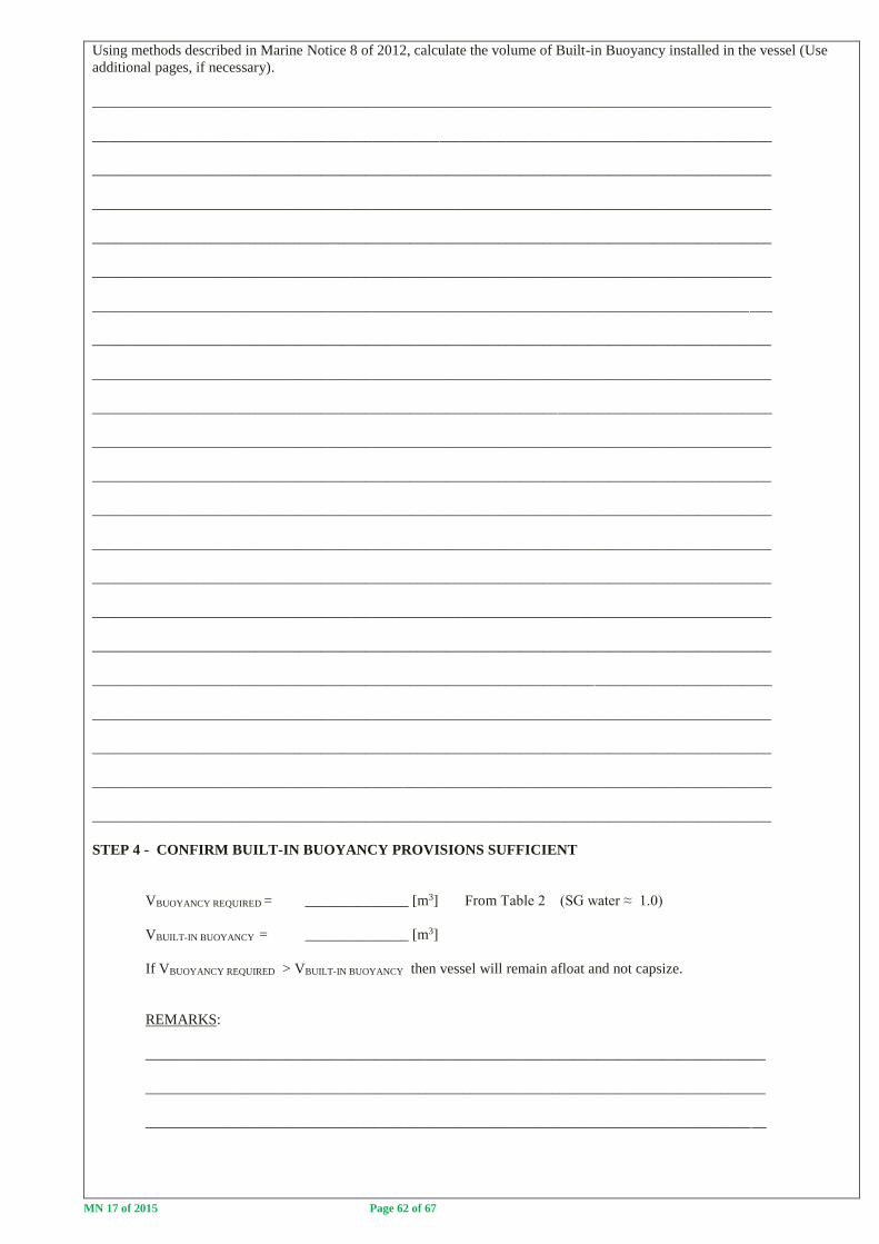
MN 17 of 2015 Page 62 of 67
Using methods described in Marine Notice 8 of 2012, calculate the volume of Built-in Buoyancy installed in the vessel (Use
additional pages, if necessary).
____________________________________________________________________________________________
____________________________________________________________________________________________
____________________________________________________________________________________________
____________________________________________________________________________________________
____________________________________________________________________________________________
____________________________________________________________________________________________
____________________________________________________________________________________________
____________________________________________________________________________________________
____________________________________________________________________________________________
____________________________________________________________________________________________
____________________________________________________________________________________________
____________________________________________________________________________________________
____________________________________________________________________________________________
____________________________________________________________________________________________
____________________________________________________________________________________________
____________________________________________________________________________________________
____________________________________________________________________________________________
____________________________________________________________________________________________
____________________________________________________________________________________________
____________________________________________________________________________________________
____________________________________________________________________________________________
____________________________________________________________________________________________
STEP 4 - CONFIRM BUILT-IN BUOYANCY PROVISIONS SUFFICIENT
VBUOYANCY REQUIRED = ______________ [m3] From Table 2 (SG water ≈ 1.0)
VBUILT-IN BUOYANCY = ______________ [m3]
If VBUOYANCY REQUIRED > VBUILT-IN BUOYANCY then vessel will remain afloat and not capsize.
REMARKS:
____________________________________________________________________________________
____________________________________________________________________________________
____________________________________________________________________________________

MN 17 of 2015 Page 63 of 67
Part F2 – Theoretical Compliance (Use additional pages as required)
Part F2c - Multihulls
Notes 1. Theoretical calculations may only be carried out by surveyors if the vessel is provided with
built-in buoyancy. In the event of the vessel being provided with watertight sub-divisions, the owner must
either prove compliance practically or make use of the services of a naval architect to prove theoretical
compliance.
2. If the below deck volume is filled with built-in buoyancy with 100% permeability eg.
closed cell polyurethane foam and the vessel deck is above the waterline in the fully loaded condition, then it
is not necessary to carry out a theoretical damaged stability calculation as no water ingress into the hull will
take place in the event of damage.
With reference to the above sketch; List the following vessel particulars:
a. Deck Length ___________________________ [m]
b. Breadth ___________________________ [m]
c. Depth ___________________________ [m]
STEP 1 - CALCULATION OF VESSEL WEIGHT
Vessel weight = Lightweight + Deadweight . . . . . . (1)
The vessel weight may either be obtained by weighing the boat or by Archimedes Principle
ie.Weight of Boat = Weight of Water Displaced by Boat
If the weight of the boat is obtained by weighing, complete table 1 below:
Description Weight [kg]
Weight of Boat (as weighed)
Less Engine weight(s)
Less Miscellaneous weights
Therefore; Lightweight of boat =
Table 1
D
B
LDECK
Vessel Deck

MN 17 of 2015 Page 64 of 67
If the vessel lightweight is to be calculated from Archimedes Principle the shape of the hull must be such that the hull volume
can easily be calculated using Basic Geometric Formula (As addressed in Marine Notice 8 of 2012). If this cannot be done then
the owner must make use of the services of a Naval Architect to determine the vessel weight.
MW = VUNDERWATER HULL SECTION . . . . . (2)
Using basic geometry equations calculate the weight of the multihull vessel using equation (2) in the space below (use
additional pages if required) and then complete Table 1.
___________________________________________________________________________________________
____________________________________________________________________________________________
____________________________________________________________________________________________
____________________________________________________________________________________________
____________________________________________________________________________________________
____________________________________________________________________________________________
____________________________________________________________________________________________
____________________________________________________________________________________________
____________________________________________________________________________________________
____________________________________________________________________________________________
____________________________________________________________________________________________
____________________________________________________________________________________________
____________________________________________________________________________________________
____________________________________________________________________________________________
____________________________________________________________________________________________
____________________________________________________________________________________________
____________________________________________________________________________________________
____________________________________________________________________________________________
____________________________________________________________________________________________
____________________________________________________________________________________________
WATERLINE
DECK
- UNDERWATER HULL SECTIONS

MN 17 of 2015 Page 65 of 67
Determine the total weight of the boat in the loaded condition by completing the following table:
Description Weight [kg] Weight [kg]
Lightweight of Boat
Add Passengers & Crew (82.5 kg per person)
Add Engine weights
Add Fuel weight
Add Safety Equipment weight
Add weight of passenger & crew effects
Add Miscellaneous weights
Therefore; Total Weight of Boat (Worst Load Condition)
Table 2
STEP 2 - DETERMINE THE AMOUNT OF INSTALLED BUILT-IN BUOYANCY
The boat is required to remain afloat when fully flooded with positive transverse stability in its worst envisaged load condition.
Built-in Buoyancy for the Total Weight of the Boat as determined in Table 2 must therefore be provided below the deck.
Draw a sketch of the built-in buoyancy provided in the vessel below clearly indicating the location(s) and type of built-in
buoyancy installed:
Remarks:
____________________________________________________________________________________________
____________________________________________________________________________________________
____________________________________________________________________________________________
____________________________________________________________________________________________
____________________________________________________________________________________________
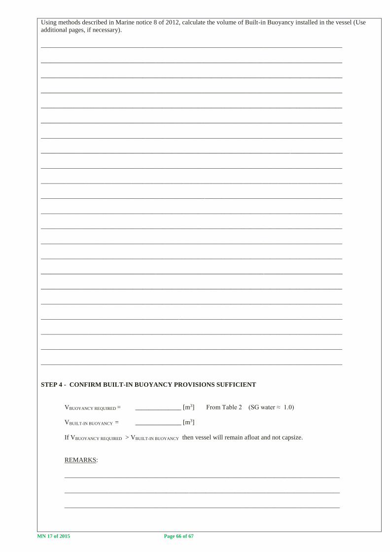
MN 17 of 2015 Page 66 of 67
Using methods described in Marine notice 8 of 2012, calculate the volume of Built-in Buoyancy installed in the vessel (Use
additional pages, if necessary).
____________________________________________________________________________________________
____________________________________________________________________________________________
____________________________________________________________________________________________
____________________________________________________________________________________________
____________________________________________________________________________________________
____________________________________________________________________________________________
____________________________________________________________________________________________
____________________________________________________________________________________________
____________________________________________________________________________________________
____________________________________________________________________________________________
____________________________________________________________________________________________
____________________________________________________________________________________________
____________________________________________________________________________________________
____________________________________________________________________________________________
____________________________________________________________________________________________
____________________________________________________________________________________________
____________________________________________________________________________________________
____________________________________________________________________________________________
____________________________________________________________________________________________
____________________________________________________________________________________________
____________________________________________________________________________________________
____________________________________________________________________________________________
STEP 4 - CONFIRM BUILT-IN BUOYANCY PROVISIONS SUFFICIENT
VBUOYANCY REQUIRED = ______________ [m3] From Table 2 (SG water ≈ 1.0)
VBUILT-IN BUOYANCY = ______________ [m3]
If VBUOYANCY REQUIRED > VBUILT-IN BUOYANCY then vessel will remain afloat and not capsize.
REMARKS:
____________________________________________________________________________________
____________________________________________________________________________________
____________________________________________________________________________________

MN 17 of 2015 Page 67 of 67
PRACTICAL STABILITY TEST
RESULTS SUMMARY PAGE
A. INTACT STABILITY
i. Minimum Freeboard
Required: ________________________________________
Achieved: ________________________________________
ii. Partial Heeling Moment
Required: ________________________________________
Achieved: ________________________________________
iii. Maximum Heeling Moment
Required: ________________________________________
Achieved: ________________________________________
B. DAMAGED STABILITY
Required: ________________________________________
Achieved: ________________________________________
EXEMPTIONS/REMARKS:
___________________________________________________________________________________________
___________________________________________________________________________________________
___________________________________________________________________________________________
___________________________________________________________________________________________
___________________________________________________________________________________________
___________________________________________________________________________________________
___________________________________________________________________________________________
________________________________________ ____________________
SURVEYOR NAME & SIGNATURE DATE
________________________________________ ____________________
PRINCIPAL OFFICER SIGNATURE DATE

![THE 19TH INTERNATIONAL MARITIME LAW A M 2018 · NATIONAL LAW UNIVERSITY, JODHPUR ... Dreyfus, [1925] ... Sea Success Maritime Inc v African Maritime Carriers Ltd, [2005]](https://img.pdfslide.us/doc/110x75/5b80c7237f8b9aeb088e06b3/the-19th-international-maritime-law-a-m-national-law-university-jodhpur-.jpg)