Embed Size (px)
Citation preview

Paper 070IC-0001 Topic: Internal Combustion and Gas Turbine Engines
8th U. S. National Combustion Meeting Organized by the Western States Section of the Combustion Institute
and hosted by the University of Utah May 19-22, 2013
Soot & Internal combustion and gas turbine engines
Chung-Hsuan Huang and Randy L. Vander Wal
John and Willie Leone Family Department of Energy and Mineral Engineering, & The EMS Energy Institute
Pennsylvania State University,
University Park , Pennsylvania 16802, USA Abstract
Particulate matter, soot, from jet engines is relevant to environmental and health concerns. In this study, JP-8, HRJ (hydro-treated renewable jet) and FT (Fischer-Tropsch) fuels were tested in a CFM56-2C1 engine on a DC-9 aircraft. Comparisons of PM physical structure at length scales spanning aggregate to primary particle to nanostructure, all by TEM, are reported. Petroleum based JP-8 derived soot shows the nanostructure progression from amorphous to graphitic-like as a function of increasing engine power. Soots from the renewable HRJ and FT fuels exhibit significant nanostructure at each power level. Results are interpreted in terms of different soot formation regions with associated variations in temperature and local equivalence ratio. The driver for such differences is the nascent fuel composition, more specifically the different classes of components and associated pyrolytic and oxidative kinetics.
1. Introduction
Jet aircraft are a unique source of carbonaceous particles, contributing to both ground pollution in and around airports but also to soot in the upper troposphere and lower stratosphere [1, 2]. The environmental impacts (e.g. radiative forcing, cloud formation, absorbing solar radiation) of soot produced by jet aircraft have raised significant attention given soot’s multiple roles [3-6]. The health effects associated with soot particles have also received increasing recognition [7]. At airports, emissions from aircraft idling, taxiing, and take-off represent a significant source of particles in the surrounding (and often urban) environment [8]. Although soot aggregates’ size is generally beyond the nanoscale, small aggregates containing one to a few primary particles (subunits) are less than 100 nm in geometric dimension and can penetrate to the deepest regions of the lung, the alveoli. Such deep penetration generally precludes their exhalation, resulting in their entrapment. Thereafter the biological response will depend upon their composition and especially surface chemistry [9].
In situ (chase) [10] or ambient (airport field) [11] emission studies are few in number, most campaigns are conducted on stationary aircraft or engine test stands. During these campaigns, gaseous and particle emissions are measured as a function of engine power level and fuel type. For example, in 2004, 2007 and 2010, Corporan and Cheng et al. [12-14] tested a series of helicopter turboshaft engines with various fuels – JP8, Fischer-Tropsch (FT) and additive-doped versions of these fuels at various engine power levels – idle, cruse and maximum. From these campaigns they concluded that the FT and additive-doped fuels could significantly reduce the PM as measured by reduction in particle number density (PND), mass concentration and by size distribution. The elemental carbon and sulfate concentrations were found to increase with increasing engine power. In 2010, Kinsey et al. reported on previous NASA-led fuel campaigns, APEX 1, 2, and 3 [15-17]. During these campaigns gas and particle emissions were systematically studied as a function of engine power level across a series of jet engines with JP-8, sulfur and aromatic doped JP-8 fuels. Engine performance, and associated emission characterizations were performed. Key advantages of such ground-based field campaigns are as follows: (1) the conditions of emission sampling can be precisely controlled, (2) the varied emissions as a function of engine power level and fuel can be intensively characterized by both real-time and extractive, analyses, and (3) testing cycles with varied fuels and over broader power levels are more readily performed than in-flight.

2
The Alternative Aviation Fuel Experiment II (AAFEX II), a NASA-led ground-based field campaign was carried out at NASA Dryden facilities in Palmdale, California. During the campaign, the experiments were conducted on PM emissions as produced by a GE CFM-56-2C engine aboard a (NASA) DC-8 aircraft, parked on the runway. Our measurement focus was on soot particle structure, across the spectrum of length scales ranging from aggregate to primary particle and internal “nano” structure. Each scale carries information regarding aerosol dynamics or pre-combustion chemistry stemming from fuel composition, for the same engine, across power levels. 2. Methods
Particulate sampling. During the AAFEX II campaign, we designed and implemented a sampling probe (shown in Fig. 1 left) that provided direct collection of soot upon a TEM grid. The key advantage to our collection during the campaign was the direct collection of the soot from the aerosol phase [18]. The sampling probe rake located at 1m and 30m of the port (L1) and starboard (R1) engines, two water-cooled sampling probe rakes directed raw exhaust emissions to various sampling stations. Our sample probe rake at the exit of the R1 engine and downstream manifold systems were connected by ¼” stainless steel tubing lines, each covered by PTFE heating cable at 120oC to avoid water condensation. One of these probes, designated as the particle probe and associated sampling line was also diluted with N2 gas. Conversely the gas probe carried only raw, undiluted exhaust gases. The soot sampling system (downstream from these lines, housed in a trailer) was designed with 7 individual lines (as shown in Fig. 1) permitting each engine power level to be sampled separately. A bypass line allowed for switching between dedicated sample lines as engine power was varied in each run. Each sampling line was connected with two ball valves for manual control of sampling time and to reduce the pressure drop when switching to the next sampling line. To permit HRTEM, Lacy carbon grids were used. The TEM grid is held within a brass clip that is mounted upon a ¼ inch diameter brass rod, approximately 2 inches in length. Insertion of the post thru a ¼ inch swagelock T-fitting provided a method for plumbing into sample lines with easy interchange of the held grid. Complimentary samples include soot collected on filters were included in the direct sampling line for quantification of soot concentration by opacity measurements.
Particulate sampling sequence and durations were dictated by a pre-planned sequence of engine power settings for varied durations given fuel consumption and engine temperature considerations. During the tests, the engines were set to 6 different power settings over the range from 4% to 100% of maximum rated thrust (with corresponding fuel flow rates of 1000-7600 lbs. per hour). This power range covers ground-idle, intermediate, cruse, and take-off levels. The tested fuels, Fischer-Tropsch and hydro-treated renewable jet fuels are essentially paraffinic in content, differing in their degree of branching (e.g. FT-Sasol is characterized by a high degree of branching) and only JP-8 has a substantial ~ 18% aromatic component.
Jet Exhaust
I.D.:0.042"
N2 dilute gas
N2 dilute gas
Jet Exhaust
I.D.:0.088"
Particle probe
Gas probe
Sample probesA
4%
7%
30%
65%
85%
100%
Exhaust
Bypass
Flow
Lacy carbon
copper gridQuartz filter
& 1000 mesh gold
Soot sampling manifold B Figure 1. Schematics of the (A) sample probes: particle and gas probes; (B) soot sampling manifold.
Nanostructure Characterization. Initial TEM images were taken using a JEOL 2010F, high resolution TEM (HRTEM), having nominal resolution of 0.14 nm with Gatan Image Filter (GIF) for digital imaging featuring live Fourier transforms having nominal resolution of 0.14 nm. The instrument was operated at 200 keV using field emission source. Gatan image software v. 3.4 was used for microscope operation. Generally 4-6 widely separated regions were examined on each grid primarily to ensure representative images and secondarily to ensure even coverage (as an indicator of flow uniformity & sampling by deposition).
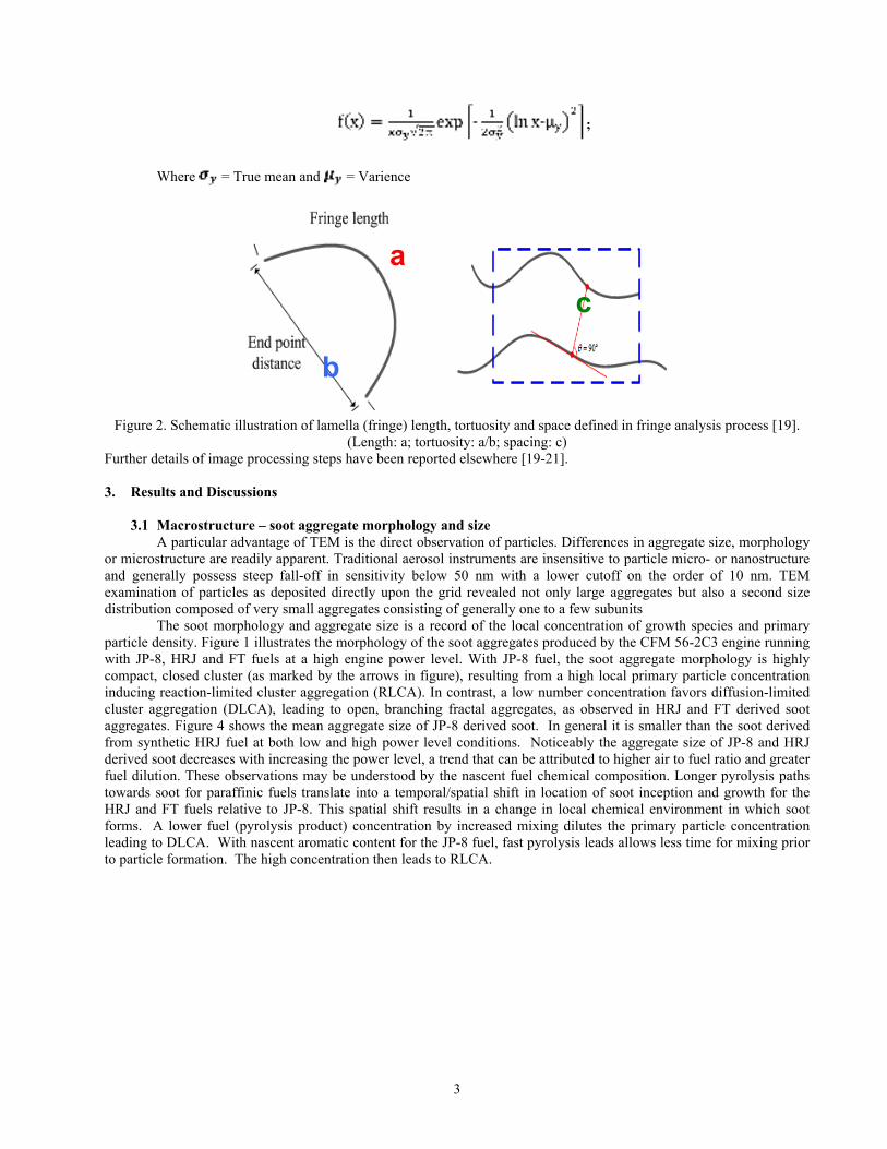
Digital images were acquired and subsequently processed using custom algorithms [19] written with Matlab software, a product of Math Works, Inc., Natick, MA. Nanostructure parameters of fringe length, separation and tortuosity based on the processed skeletonized and enhanced TEM images were processed by these algorithms Analysis results were exported to the program KaleidaGraphTM for subsequent plotting and data analyses. Figure 2 is an illustration of the quantified features, lamella (fringe) length, tortuosity and space of soot. The Histogram data plots summarizing the distribution of a nanostructural parameter were fitted by two-parameter lognormal density function, f(x).
3
;
Where = True mean and = Varience
Figure 2. Schematic illustration of lamella (fringe) length, tortuosity and space defined in fringe analysis process [19].
(Length: a; tortuosity: a/b; spacing: c) Further details of image processing steps have been reported elsewhere [19-21]. 3. Results and Discussions
3.1 Macrostructure – soot aggregate morphology and size
A particular advantage of TEM is the direct observation of particles. Differences in aggregate size, morphology or microstructure are readily apparent. Traditional aerosol instruments are insensitive to particle micro- or nanostructure and generally possess steep fall-off in sensitivity below 50 nm with a lower cutoff on the order of 10 nm. TEM examination of particles as deposited directly upon the grid revealed not only large aggregates but also a second size distribution composed of very small aggregates consisting of generally one to a few subunits
The soot morphology and aggregate size is a record of the local concentration of growth species and primary particle density. Figure 1 illustrates the morphology of the soot aggregates produced by the CFM 56-2C3 engine running with JP-8, HRJ and FT fuels at a high engine power level. With JP-8 fuel, the soot aggregate morphology is highly compact, closed cluster (as marked by the arrows in figure), resulting from a high local primary particle concentration inducing reaction-limited cluster aggregation (RLCA). In contrast, a low number concentration favors diffusion-limited cluster aggregation (DLCA), leading to open, branching fractal aggregates, as observed in HRJ and FT derived soot aggregates. Figure 4 shows the mean aggregate size of JP-8 derived soot. In general it is smaller than the soot derived from synthetic HRJ fuel at both low and high power level conditions. Noticeably the aggregate size of JP-8 and HRJ derived soot decreases with increasing the power level, a trend that can be attributed to higher air to fuel ratio and greater fuel dilution. These observations may be understood by the nascent fuel chemical composition. Longer pyrolysis paths towards soot for paraffinic fuels translate into a temporal/spatial shift in location of soot inception and growth for the HRJ and FT fuels relative to JP-8. This spatial shift results in a change in local chemical environment in which soot forms. A lower fuel (pyrolysis product) concentration by increased mixing dilutes the primary particle concentration leading to DLCA. With nascent aromatic content for the JP-8 fuel, fast pyrolysis leads allows less time for mixing prior to particle formation. The high concentration then leads to RLCA.
c a
b

4
Figure 3. TEM images illustrating the morphology of JP-8, HRJ, and FT (image sequence from left to right) derived soot at high engine power level.
0
50
100
150
200
250
300
350
0 20 40 60 80 100 120
JP-8
HRJ
Ag
gre
gate
siz
e (
nm
)
Engine power level (%) Figure 4. Aggregate sizes of JP-8 and HRJ derived soot at 7% and 100%.
3.2 Microstructure – primary particle morphology and size
Figure 5 shows the morphology of soot primary particle derived from JP-8, HRJ, and FT at low and high power levels. For JP-8 the primary particles diverge substantially in their geometric definition (distinctiveness) with engine power. At low power, for JP-8, primary particles are unrecognizable and highly fused because coalescence occurs early. Only at high power is aggregate substructure distinct and primary particles become distinguishable. This trend for JP-8 is attributed to fuel dilution at high power spreading particle growth over time and space. With the delayed chemical onset to soot inception for (paraffinic-based) synthetic fuels, the primary particles form and grow first, thereafter followed by particle coalescence, resulting in distinct aggregate substructure with recognizable primary particles. Such substructure is observed at all power levels for HRJ and FT derived soots. The variation observed for JP-8 across engine powers is thus ultimately traced to the nascent fuel composition and associated fuel pyrolysis kinetics.
Figure 6 shows the primary particle size distributions ranging from low (4%) to high (100%) engine power levels for JP-8, HRJ & FT derived soot. With higher power, fuel-air mixing becomes more extensive. Though the higher temperature may accelerate fuel pyrolysis reactions, increased fuel-air mixing lowers local equivalence ratio, Φ resulting in foreshortened time for particle growth for the FT and HRJ fuels. Primary particle size becomes smaller then with increasing power. This would yet happen for JP-8 too but there is a tradeoff. Even though final particle growth may be cut short or proceed less rapidly, temperature elevation in the upstream region of soot nucleation substantially accelerates inception. An accelerated start appears to outweigh or offset a downstream, decreased growth rate due to increased mixing and overall lowered species concentrations. This would account for the yet increasing primary particle size found for JP-8 fuel with increasing power level.

5
Moreover, for JP-8 fuel, further increases in power will activate thermally driven pyrolysis of the paraffinic and cyclo-paraffinic compounds, creating a new set of aromatics for growth, thereby extending the soot growth time for this fuel. Since the renewable fuels required such conditions for soot onset, little is gained (from the standpoint of soot production) by such temperature increases at higher power levels. For the renewable fuels earlier onset seems to foreshorten primary particle growth. In fact the greater turbulence mixing counters soot production from such a fuel with kinetically delayed onset to soot inception.
Consequently for JP-8 fuel there is a strong correlation between primary particle size and engine power whereas not so for renewable fuels. Such correlations or lack thereof trace back to the original fuel compositional differences. Larger (primary) particles arise from higher concentrations of species and/or longer times for growth. The latter is less likely with increasing engine power simply because of higher gas velocities (and presumably shorter residence times) within soot forming regions in the turbine. Temperature in this case, governing soot onset and further growth may matter more.
Figure 5. TEM images illustrating primary particle morphology of JP-8, HRJ and FT derived soot (image sequence from left to right) at low (top row) and high (bottom row) engine power levels.

6
15
20
25
30
35
0 20 40 60 80 100
JP-8
HRJ
FT
Pri
mary
part
icle
siz
e (
nm
)
Engine power level (%) Figure 6. Primary particle distribution means of JP-8, HRJ & FT derived soot across engine power levels from 4% to 100%.
3.3 Nanostructure – soot nanostructure and the quantification
Figure 7 is the summary of quantified nanostructure of soots derived from JP-8 and HRJ fuels. As shown, with increasing power the JP-8 derived soot lamella elongate while the average tortuosity becomes less (straighter). For the renewable fuel, given the premise that fuel decomposition processes are occurring in an environment that is lower in fuel concentration (lower Φ) and in which significant oxidation is also occurring leads to more varied species. Less defined nanostructure with less homogeneity across the particles then results. Nevertheless nanostructure is pronounced in these soots at all power levels, not just the highest. Figure 8 shows the nanostructure of soot derived from JP-8, HRJ and FT fuels at low and high engine power levels. The JP-8 derived (~18% aromatic and ~82% paraffin-derived) soot at low engine power level retains mainly random, amorphous type structure. In contrast, the nanostructure of soot derived from renewable fuels, HRJ & FT, at lower engine power level contains substantial curved lamella (fullerenic-like structure). At high engine power level, the soot derived from JP-8 exhibits a more graphitic-like structure. In contrast, soot from the renewable fuels, HRJ & FT, retains a highly curved, fullerenic-like appearance, (as marked with arrows in the figure) similar to that generated at low engine power levels. Soot nanostructure is proposed to reflect the species available for soot growth. That the soot from the renewable fuels retains nanostructure across all power levels while JP-8 does not reflects the combustion chemistry dependence upon the nascent fuel. This highly curved nanostructure attest to the delayed paraffinic pyrolysis, and absence of unsaturated hydrocarbons and aromatics in the nascent fuel. This composition results in a longer soot inception time, leading in turn to increased fuel-air mixing with resulting formation of oxygenated intermediates and odd numbered carbon species such as cyclopentadiene and other C5 containing species. Notably this occurs at the molecular level prior to soot formation. Conversely fullerenic structure for JP-8 derived soot is largely absent, indicating a relative absence of such species. JP-8’s aromatic content resembles an advanced pyrolysis state. Soot formation and growth occur rapidly once a temperature threshold is crossed. The comparatively low temperature value ensures prompt soot formation with consequence of reduced mixing by turbulence and comparatively less C5 and related species. At high power, a higher initial fuel concentration for both fuels could impede the oxygen-assisted pathway towards C5 formation, as suggested by the reduced fullerenic nanostructure for each fuel, but just not at equal rates. This highly curved nanostructure is interpreted as reflecting the incorporation of C5 species into the carbon lamella. MD simulations indicate that direct addition of C5 or larger PAHs containing C5 directly from the gas-phase is deemed a more likely route for the significant level of fullerenic structure observed [22]. These species are not an original component of fuel. Instead they are believed to arise by partial oxidation, as next outlined.
Delayed or extended fuel pyrolysis results in an increase in an increase in fuel and air pre-mixing. Paraffins will decompose to C1 and C3 species via oxidative degradation or partial oxidation of the mixture [23, 24]. C3 in particular can form allyl or propargyl radicals [25]. These along with C2 species (ethylene, acetylene) can form C5 via a bimolecular reaction [26]. During initial oxidation, oxygen extracts H-atoms during oxidation yielding unsaturated hydrocarbons. Oxygen will also open new pathways to aromatic formation from paraffins, such as C6 by C3+C3, a more

7
facile reaction process than C6 formation via a sequence of C2 additions [27]. Another path of C5 formation is via partial oxidation of benzene; phenoxy radical formation followed by subsequent elimination of CO to yield cyclopentadiene [28]. Thus both routes towards C5 require partial oxidation for producing the appropriate odd-carbon species in sufficient supply. In radical form, the cyclopentadienyl radical is primed for addition to either the soot particle surface at corresponding radical sites or can readily undergo radical conjugation to other species such as benzene resulting in deviation from the C6 PAH. In summary oxygen alters the concentration and identity of species contributing to aromatics and soot growth.
0.8
0.85
0.9
0.95
1
1.05
1.1
1.15
1.16
1.18
1.2
1.22
1.24
1.26
1.28
1.3
0 20 40 60 80 100 120
Length
Tortuosity
Len
gth
(n
m) T
ortu
osity
Engine power level (%)
0.95
1
1.05
1.1
1.15
1.2
1.15
1.175
1.2
1.225
1.25
0 20 40 60 80 100 120
Length
Tortuosity
Len
gth
(n
m) T
ortu
osity
Engine power level (%) Figure 7. Lamella length and tortuosity distribution means of JP-8 (left) and HRJ (right) derived soot across all power levels.
Figure 8. HRTEM images of JP-8, HRJ and FT derived soot (image sequence from left to right) at low (top row) and high (bottom row) engine power levels.

8
4. Conclusions
In this paper, comparative soot physical characterization data for a commercial class gas turbine engine CFM56-2C burning petroleum-based JP-8 fuel, and renewable FT, HRJ fuels are reported. By these comparisons the pre-combustion fuel pyrolysis and initial soot formation processes are governed by the nascent fuel molecular composition. The key findings are summarized in following section. 1. A more compact aggregate morphology of JP-8 derived soot is attributed to a higher Φ in soot forming regions
resulting in a higher initial primary particle density, feeding reaction-limited cluster aggregation. Conversely, the open, branched aggregate of soot produced by renewable fuels results from a lower Φ, more dilution in soot forming regions where results in a relatively lower primary particle concentration, feeding diffusion-limited cluster aggregation.
2. The primary particle size of soot derived from JP-8 (with ~ 18% aromatic content) increases as a function of increasing engine power with the soot formation occurring in early stage. On the contrary, for the renewable fuels with pure paraffinic content, the primary particle sizes decrease with increasing engine power reflecting less time and lower concentration of growth species.
3. For JP-8 derived soot, the change in nanostructure (from amorphous to graphitic-like) with increasing engine power level is related to the change in local chemical environment. In contrast, for the renewable fuels the distinct and varied types of nanostructure: chaotic with fullerenic lamella, graphitic-like with extended peripheral shells and amorphous, i.e. absence of recognizable lamella, were observed at all power levels. The evolution of nanostructure for a fuel with aromatic content and diversity for paraffinic fuels irrespective of engine operating condition suggests different formation paths, inception locations, and growth environments involving temperature and species for soot between these fuels.
Acknowledgements
This research was funded by the NASA Aeronautics Subsonic Fixed Wing (SSFW) Program, NASA Cooperative Agreement NNX09AD42A with The Pennsylvania State University, at University Park, PA 16802. The author gratefully acknowledges the assistance of sample collection during the weeks of AAFEX-II field campaign testing by Christopher M. Heath (NASA-Glenn) and overall project coordination and experimental assistance and support by Dr. Bruce Anderson (NASA-Langley). Vicky M. Bryg (USRA) is acknowledged for TEM contributions. References 1. Liu, F.; Smallwood, G. J. Radiative properties of numerically generated fractal soot aggregates: the importance of configuration averaging. J. Heat Transfer. 2010, 132, 023308-1; DOI 10.1115/1.4000245. 2. Li, H.; Liu, C.; Bi, L.; Yang, P.; Kattawar, G. W., Numerical accuracy of equivalent spherical approximations for computing ensemble-averaged properties of fractal soot aggregates. J. Quant. Spectrosc. Radiat. Transfer. 2010, 111 (14) 2127-2132; DOI 10.1016/j.jqsrt.2010.05.009. 3. Bond, T. C.; Streets, D. G.; Yarber, K. F.; Nelson, S. M.; Woo, J.-H.; Klimont, Z. A technology based global inventory of black and organic carbon emissions from combustion. J. Geophys. Res. 2004, 109 (43); D14203-43; DOI 10.1029/2003JD003697. 4. Wuebbles, D.; Gupta, M.; Ko, M. Evaluating the impacts of aviation on climate change. EOS, Trans. Am. Geophys. Union. 2007, 88 (14), 157-168; DOI 10.1029/2007EO140001. 5. Vander Wal, R. L.; Tomasek, A. J. Soot nanostructure: dependence upon synthesis conditions. Combust Flame. 2003, 136 (1-2) 129-140; DOI 10.1016/j.combustflame.2003.09.008. 6. Alfe, M.; Apicella, B.; Barbella, R.; Rouzaud, J. N.; Tregrossi, A.; Ciajolo, A.; Structure-property relationship in nanostructures of young and mature soot in premixed flames. P. Combust. Inst. 2009, 32 (1) 697-704; DOI 10.1016/j.proci.2008.06.193. 7. Teini, P. D.; Darshan, M. A.; Karwat, M. A.; Atreya, A. Observations of nascent soot: molecular deposition and particle morphology. Combust Flame. 2011, 158 (10) 2045-2055; DOI 10.1016/j.combustflame.2011.03.005. 8. Popovicheva, O. B.; Persiantseva, N. M.; Kuznetsov, B. V.; Rakhmanova, T. A.; Shonija, N. K.; Suzanne, J.; Ferry, D. Microstructure and water adsorbability of aircraft combustor soots and kerosene flame soots: towards an aircraft-generated soot laboratory surrogate. J. Phys. Chem. A. 2003, 107 (47), 10046-10054; DOI 10.1021/jp034402f.

9
9. Sgro, L. A.; Simonelli, A.; Pascarella, L.; Minutolo, P.; Guarnieri, D.; Sannolo, N.; Netti, P.; D’Anna, A.; Toxicological properties of nanoparticles of organic compounds (NOC) from flames and vehicle exhausts. Environ. Sci. Technol. 2009, 43 (7) 2608–2613; DOI: 10.1021/es8034768. 10. Schumann, U.; Strom, J.; Busen, R.; Baumann, R.; Glerens, K.; Krautstrunk, M.; Schroder, F. P.; Stingl, J. In situ observations of particles in jet aircraft exhausts and contrails for different sulfur-containing fuels. J. Geophys. Res-Atmos. 1996, 101 (D3) 6853-6869; DOI 10.1029/95JD03405. 11. Herndon, S. C.; Jayne, J. T.; Lobo, P.; Onasch, T. B.; Fleming, G.; Hagen, D. E.; Whitefield, P. D.; Miake-Lye, R. C. Commercial aircraft engine emissions characterization of in-use aircraft at Hartsfield-Jackson Atlanta International Airport. Environ. Sci. Technol. 2008, 42 (6) 1877-1883; DOI 10.1021/es072029. 12. Corporan, E.; DeWitt, M.; Wagner, M. Evaluation of soot particulate mitigation additives in a T63 engine. Fuel Process. Technol. 2004, 85 (6-7) 727-742; DOI 10.1016/j.fuproc.2003.11.016. 13. Corporan, E.; DeWitt, M. J.; Belovich, V.; Pawlik, R.; Lynch, A. C.; Gord, J. R.; Meyer, T. R. Emissions characteristics of a turbine engine and research combustor burning a Fischer-Tropsch jet fuel. Energ. Fuels. 2007, 21 (5) 2615-2626; DOI 10.1021/ef070015j. 14. Cheng, M.D. and E. Corporan, A study of extractive and remote-sensing sampling and measurement of emissions from military aircraft engines. Atmos. Environ. 2010, 44 (38) 4867-4878; 10.1016/j.atmosenv.2010.08.033. 15. Kinsey, J.S., et al., Chemical Characterization of the Fine Particle Emissions from Commercial Aircraft Engines during the Aircraft Particle Emissions eXperiment (APEX) 1 to 3. Environ. Sci. Technol. 2011, 45 (8) 3415-3421. 16. Kinsey, J. S.; Hays, M. D.; Dong, Y.; Williams, D. C.; Logan, R. Physical characterization of the fine particle emissions from commercial aircraft engines during the Aircraft Particle Emissions eXperiment (APEX) 1-3. Atmos. Environ. 2010, 44 (17) 2147-2156. 17. Wey, C. C.; Anderson, B. E.; Wey, C.; Miake-Lye, R. C.; Whitefield, P. D.; Howard, R. Overview on the aircraft particle emissions experiment. J. Propul. Power. 2007, 23 (5) 898-905; DOI 10.2514/1.26406. 18. Vander Wal, R. L.; Lee, K. O.; Choi, M. Y. The effects of rapid heating of soot: Implications when using laser-induced incandescence for soot diagnostics. Combust. Flame. 1995, 102 (1-2) 200-204; DOI 10.1016/0010-2180(95)00071-D. 19. Yehliu, K., Impacts of Fuel Fromulation and Engine Operating Parameters on the Nanostructure and Reactivity of Diesel Soot. Desrtation of Energy and Mineral Engineering, Pennsylvania State Univeristy 2010. 20. Vander Wal, R. L.; Tomasek, A. J.; Street, K.; Hull, D. R.; Thompson, W. K. Carbon nanostructure examined by lattice fringe analysis of high-resolution transmission electron microscopy images. Appl. Spectros. 2004, 58 (2) 230-237; DOI 10.1366/000370204322842986. 21. Yehliu, K.; Vander Wal, R. L.; Boehman, A. L. Development of an HRTEM image analysis method to quantify carbon nanostructure. Combust. Flame. 2011, 158 (9) 1837-1851; DOI 10.1016/j.combustflame.2011.01.009. 22. Frenklach, M. On surface growth mechanism of soot particles. The Twenty-Sixth Symposium (International) on Combustion, The Combustion Institute, 1996, 26:2285-2293. 23. Frenklach, M., Reaction mechanisms of soot formation in flames. Phys. Chem. Phys. Chem. 2002,4:2028-2037. 24. McEnally, C. S., Pfefferle, L. D., Atakan, B., and Kohse-Hoinghaus, K., Studies of aromatic hydrocarbon formation mechanisms in flames: Progress towards closing the fuel gap, Prog. Energ. Combust. Sci. 2006, 32:247-294. 25. McEnally, C. S., and Pfefferle, L. D., Species and soot concentration measurements in a methane/air nonpremixed flame doped with C4 hydrocarbons. Combust. Flame 1998, 115:81-92. 26. Marinov, N. M., Pitz, W. J., Westbrook, C. K., Lutz, A. E., Vincitore, A. M., Senkan, S. M., Chemical kinetic modeling of a methane opposed-flow diffusion flame and comparison to experiments. Twenty-Seventh Symposium (International) on Combustion. 1998, I:605-613. 27. Hansen, N., Miller, J. A., Kasper, T., Kohse-Hoinghaus, K., Westmoreland, P. R., Wang, J., and Cool, T., Benzene formation in premixed fuel-rich 1,3-butadiene flames. P. Combust. Inst. 2009, 32:623-630. 28. McEnally, C. S., and Pfefferle, L. D., The effects of slight premixing on fuel decomposition and hydrocarbon growth in benzene-doped methane nonpremixed flames. Combust. Flame. 2002, 129:305-323.