Embed Size (px)
Citation preview
© Lucent Technologies Page 1C. Papadias
Some Recent EU-funded MIMO Research Activities
Constantinos Papadias
Technical ManagerWireless Research Lab
Bell Laboratories, Lucent Technologies
Talk given at the 2004 Smart Antenna Workshop
Stanford University, Stanford, CAJuly 29-30, 2004
© Lucent Technologies Page 2C. Papadias
l EU-funded wireless research:– Past activities – Current program: 6th framework program (FP6)
l MIMO-related projects where we are involved:– FITNESS (FP5)– WINNER (FP6)– ACE (FP6)– OBAN (FP6)
l Wireless World Research Forum: a next-G wireless forum– Recent contributions on intelligent antennas
Outline Lucent TechnologiesBell Labs Innovations
[Integrated Project (IP)]
[Network of Excellence (NoE)]
[Specific Targeted Research Project (STREP)]
© Lucent Technologies Page 3C. Papadias
Past European activites: 4th Framework Program (FP4)
l FP4-ACTS (Advanced Communication Technology Systems)
– FRAMES (Future Radio Wideband Multiple Access Systems)Goal: to define, develop and evaluate efficient multiple access schemes for UMTS
– TSUNAMI (Technology in Smart Antennas for Universal Mobile Infrastructure)Goal: to demonstrate that it is feasible and cost effective to deploy Adaptive Antennas for UMTS
– SUNBEAM (Smart Universal Beamforming)Goal: array processing for UMTS FDD and TDD
l COST (European cooperation in scientific and technological research)
– COST 231 - Evolution of Land Mobile Radio Communications– COST 259 - Wireless Flexible Personalised Communications– COST 273 - Towards Mobile Broadband Multimedia Networks
Lucent TechnologiesBell Labs Innovations

© Lucent Technologies Page 4C. Papadias
Fifth Framework program (FP5)
l METRA(Multi-Element Transmit and Receive Antennas)MIMO techniques for UMTS
l SATURN (Smart Antenna Technology in Universal Broadband wireless Networks)Adaptive antenna techniques for UMTS TDD and WLAN
l ASILUM (Advanced Signal processing for Link capacity increase inUMTS)Beamforming and Multi-User Detection for UMTS
l I-METRA (Intelligent Multi-Element Transmit and Receive Antennas)Re-configurable MIMO for UMTS
l FITNESS: Fourth-generation Intelligent Transparent Networks Enhanced through Space-time Systems
Lucent TechnologiesBell Labs Innovations
l Logistics: – Duration: 1999-2002; budget: €3.6B for Information Society Technologies (IST)
l Smart antenna related projects:

© Lucent Technologies Page 5C. Papadias
FP6
l Sixth Framework Programme (FP6):– Information Society Technologies: €3.6B for 2003-2006
l First Call (April ’03): €1.070B
– Mobile and wireless systems beyond 3G: €90M
l Broad goal:
l Main ‘‘instruments’’:– Integrated Projects (IP’s)– Networks of Excellence (NoE’s)– Specific Targetted Projects (STREP’s)
Lucent TechnologiesBell Labs Innovations
‘‘Anywhere anytime natural and enjoyable access to IST services for ALL’’

© Lucent Technologies Page 6C. Papadias
Fourth-generation Intelligent Transparent Networks
Enhanced through Space-time Systems
IST-2000-30116
Lucent TechnologiesBell Labs Innovations
FITNESS:
© Lucent Technologies Page 7C. Papadias
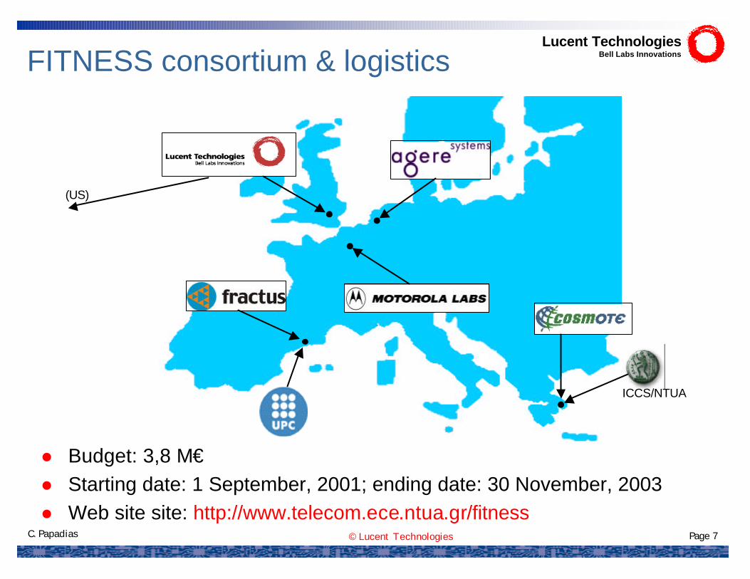
FITNESS consortium & logistics
ICCS/NTUA
(US)
Lucent TechnologiesBell Labs Innovations
l Budget: 3,8 M€l Starting date: 1 September, 2001; ending date: 30 November, 2003l Web site site: http://www.telecom.ece.ntua.gr/fitness
© Lucent Technologies Page 8C. Papadias
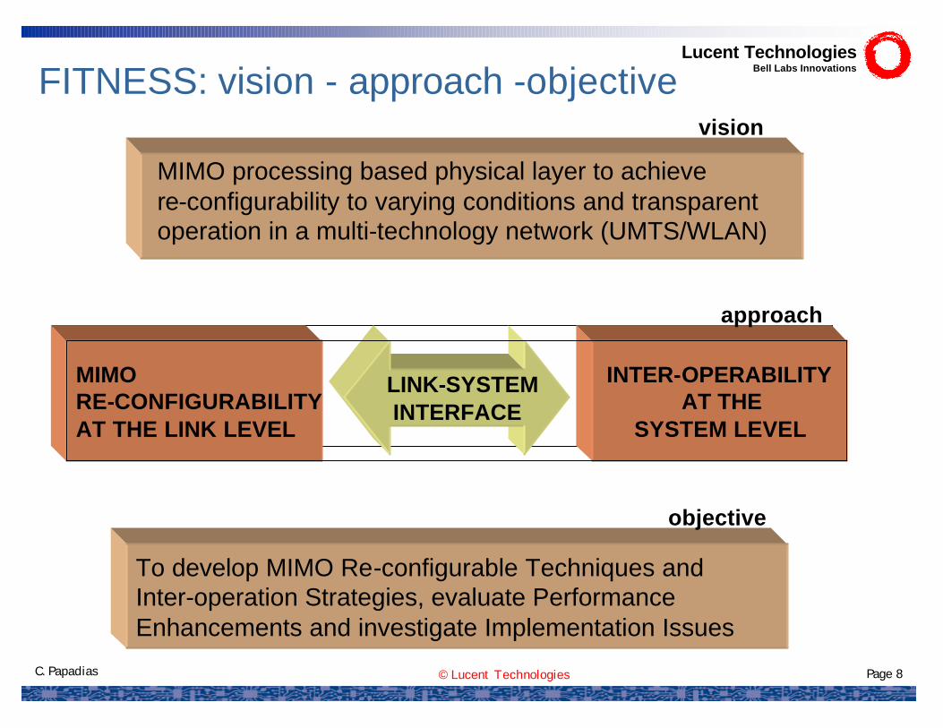
FITNESS: vision - approach -objective
MIMO processing based physical layer to achieve re-configurability to varying conditions and transparent operation in a multi-technology network (UMTS/WLAN)
MIMO RE-CONFIGURABILITY AT THE LINK LEVEL
LINK-SYSTEM INTERFACE
INTER-OPERABILITYAT THE
SYSTEM LEVEL
To develop MIMO Re-configurable Techniques and Inter-operation Strategies, evaluate Performance Enhancements and investigate Implementation Issues
vision
approach
objective
Lucent TechnologiesBell Labs Innovations

© Lucent Technologies Page 9C. Papadias
ü Reconfigurable algorithms for UMTS
ü Reconfigurable algorithms for WLAN
ü HSDPA test-bed
ü WLAN test-bed
ü Antenna studies
ü Link-to-System Interface
ü FITNESS System Level Simulations
Lucent TechnologiesBell Labs Innovations
FITNESS main technical achievements
© Lucent Technologies Page 10C. Papadias
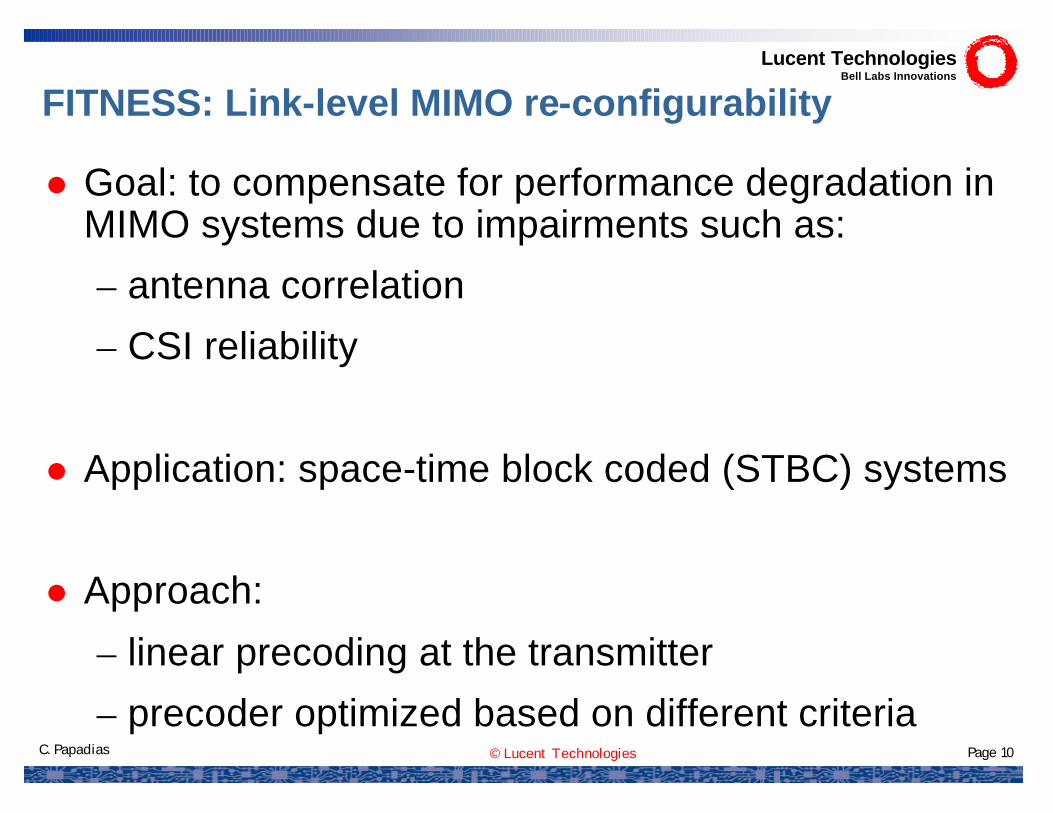
l Goal: to compensate for performance degradation in MIMO systems due to impairments such as:
– antenna correlation
– CSI reliability
l Application: space-time block coded (STBC) systems
l Approach:
– linear precoding at the transmitter
– precoder optimized based on different criteria
Lucent TechnologiesBell Labs Innovations
FITNESS: Link-level MIMO re-configurability
© Lucent Technologies Page 11C. Papadias
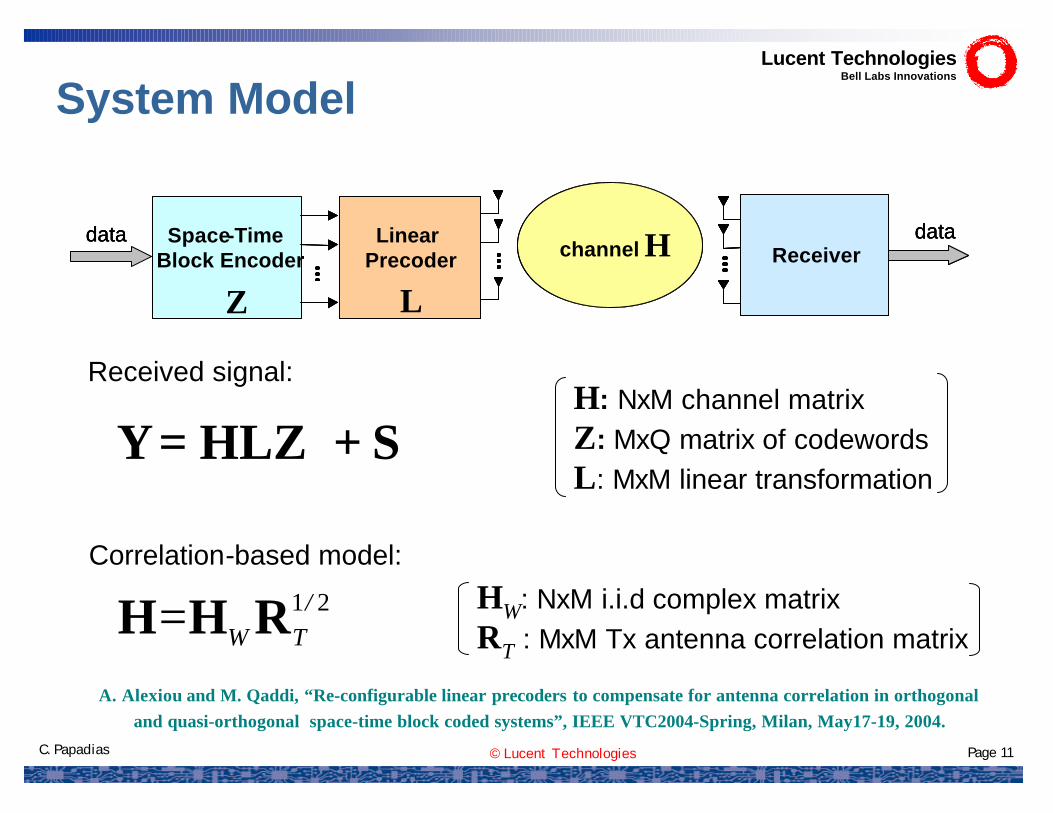
System Model
S+HLZ=Y
21/TW= RHH
Received signal:H: NxM channel matrixZ: MxQ matrix of codewordsL: MxM linear transformation
Correlation-based model:
HW: NxM i.i.d complex matrix RT : MxM Tx antenna correlation matrix
Space-Time Block Encoder
data datachannel H ReceiverLinear
Precoder
Z L
Space-Time Block Encoder
data datachannel H ReceiverLinear
PrecoderSpace-Time
Block Encoderdata data
channel H ReceiverLinear
Precoder
Z L
Lucent TechnologiesBell Labs Innovations
A. Alexiou and M. Qaddi, “Re-configurable linear precoders to compensate for antenna correlation in orthogonal and quasi-orthogonal space-time block coded systems”, IEEE VTC2004-Spring, Milan, May17-19, 2004.
© Lucent Technologies Page 12C. Papadias
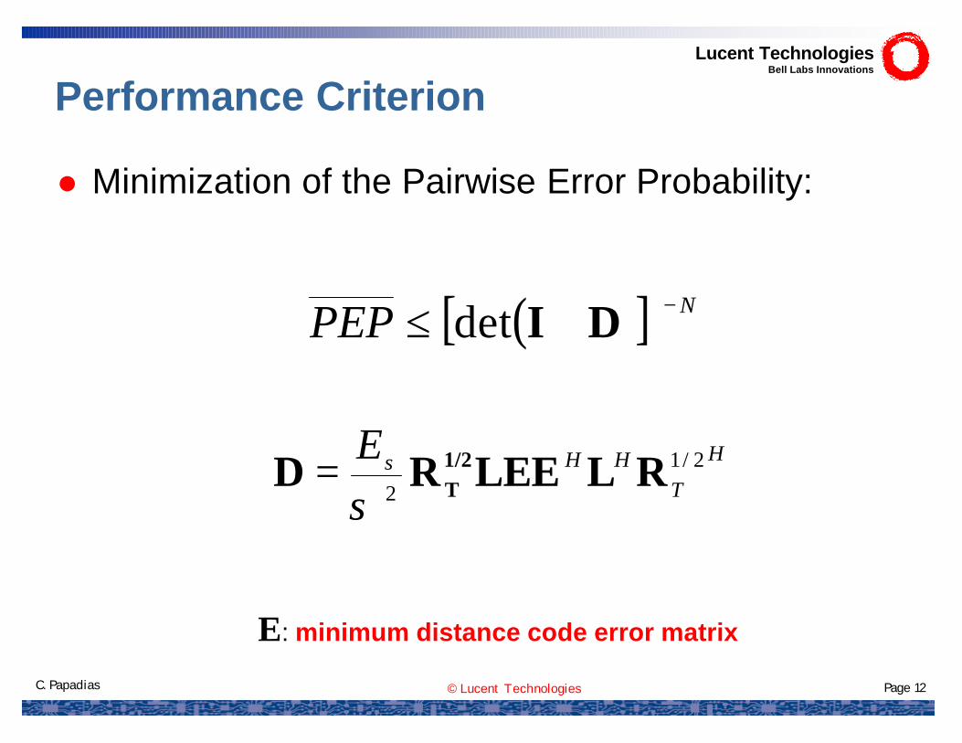
Performance Criterion
( )[ ] NPEP −+≤ DIdet
H
THHsE 2/1
2RLLEERD 1/2
Tσ=
E: minimum distance code error matrix
Lucent TechnologiesBell Labs Innovations
l Minimization of the Pairwise Error Probability:
© Lucent Technologies Page 13C. Papadias
Space-Time Block Encoder
data dataReceiverLinear
Precoder Channel H
0 0.1 0.2 0.3 0.4 0.5 0.6 0.7 0.8 0.9 12
4
6
8
10
12
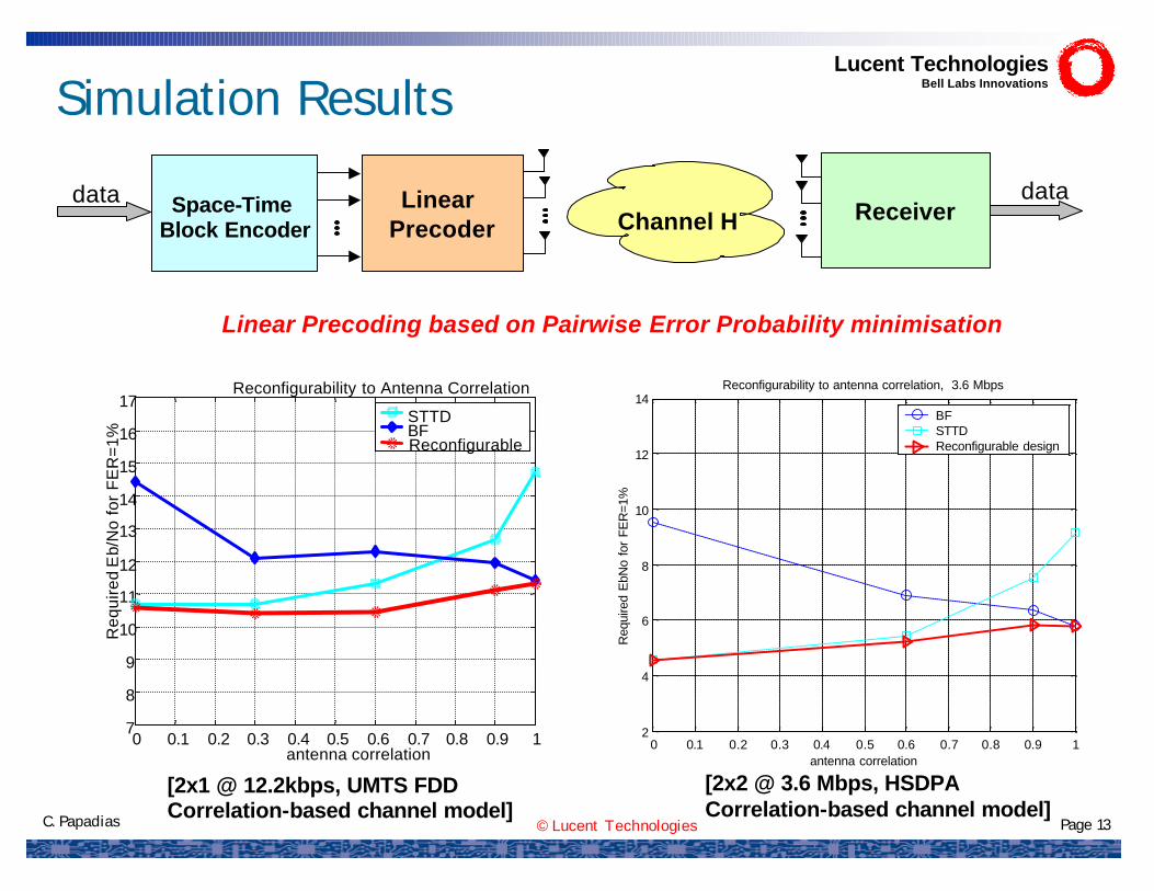
14Reconfigurability to antenna correlation, 3.6 Mbps
antenna correlation
Req
uire
d E
bNo
for
FER
=1%
BF STTD Reconfigurable design
Linear Precoding based on Pairwise Error Probability minimisation
[2x2 @ 3.6 Mbps, HSDPACorrelation-based channel model]
[2x1 @ 12.2kbps, UMTS FDDCorrelation-based channel model]
Lucent TechnologiesBell Labs Innovations
0 0.1 0.2 0.3 0.4 0.5 0.6 0.7 0.8 0.9 17
8
9
10
11
12
13
14
15
16
17
antenna correlation
Req
uire
dE
b/N
o fo
r F
ER
=1%
Reconfigurability to Antenna Correlation
STTD BF Reconfigurable
Simulation Results
© Lucent Technologies Page 14C. Papadias
0 20 40 60 80 100 1202
3
4
5
6
7
8
9
10
11
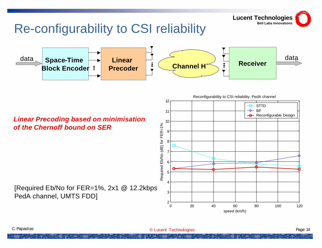
12Reconfigurability to CSI reliability, PedA channel
speed (km/h)
Req
uire
d E
b/N
o (d
B)
for
FER
=1%
STTD BF Reconfigurable Design
Space-Time Block Encoder
data dataReceiverLinear
Precoder Channel H
[Required Eb/No for FER=1%, 2x1 @ 12.2kbpsPedA channel, UMTS FDD]
Linear Precoding based on minimisation of the Chernoff bound on SER
Lucent TechnologiesBell Labs Innovations
Re-configurability to CSI reliability
© Lucent Technologies Page 15C. Papadias
-10 -5 0 5 10 1510
-5
10-4
10-3
10-2
10-1
SIR, dB
Raw
BE
RTechn. 1 Techn, 2 Re-config.
-10 -5 0 5 10 1510
-3
10-2
10-1
100
SIR, dB
PE
R
Techn. 1 Techn. 2 Re-config.
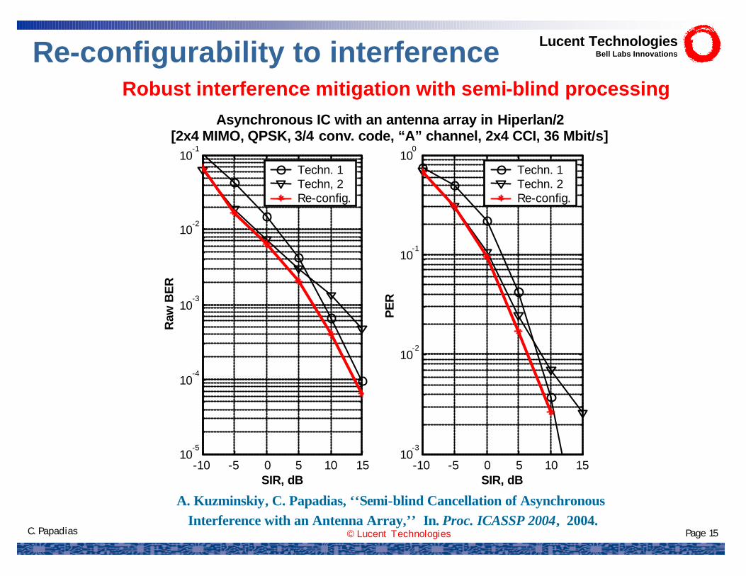
Asynchronous IC with an antenna array in Hiperlan/2[2x4 MIMO, QPSK, 3/4 conv. code, “A” channel, 2x4 CCI, 36 Mbit/s]
Robust interference mitigation with semi-blind processing
Lucent TechnologiesBell Labs InnovationsRe-configurability to interference
A. Kuzminskiy, C. Papadias, ‘‘Semi-blind Cancellation of Asynchronous Interference with an Antenna Array,’’ In. Proc. ICASSP 2004, 2004.

© Lucent Technologies Page 16C. Papadias
MIMO interference mitigation demo for HSDPA
DESIRED SIGNAL
INTERFER
ENCE
(2 transmit antennas)
(2 transmit antennas)
(4 receive antennas)
Over the air real-time interference mitigation MIMO HSDPA demo using Lucent’s BLAST chip
Lucent TechnologiesBell Labs Innovations
D. Samardzija, A. Lozano, C. Papadias, ‘‘Experimental Validation ofMIMO Multiuser Detection for UMTS High-Speed Downlink Packet Access,’’
to appear, IEEE Globecom 2004, Dallas, Texas, Nov. 29 - Dec. 3, 2004.

© Lucent Technologies Page 17C. Papadias
IST Mobile Summit, Aveiro, Portugal, June 2003
Lucent TechnologiesBell Labs Innovations
MIMO interference mitigation demo setup

© Lucent Technologies Page 18C. Papadias
Link-to-system interface
SYSTEM LEVELMultiple link (cell)
Network
Evaluation of instantaneous
MetricC=C(H)
LINK LEVELPerformance
CurvesFER(C)
H C FER
INTERFACE
§ Performance gains at the link-level do not necessarily translate into equivalent gains at the system level
§ System-level simulation, i.e. identifying the performance of the radio links between all mobiles and base stations, is of prohibitive complexity
§ A new link-to-system interface needs to be identified which represents the receiver performance as a function of specific channel realisationsover a coding-block
Lucent TechnologiesBell Labs Innovations
A. Alexiou, R. Karimi, K. Peppas, F. Lazarakis, D. Bourse, “System level simulation methodology for 4Gwireless communication systems enhanced through space-time techniques”, 7th WWRF Meeting, 3-4 December 2002, Eindhoven.
© Lucent Technologies Page 19C. Papadias
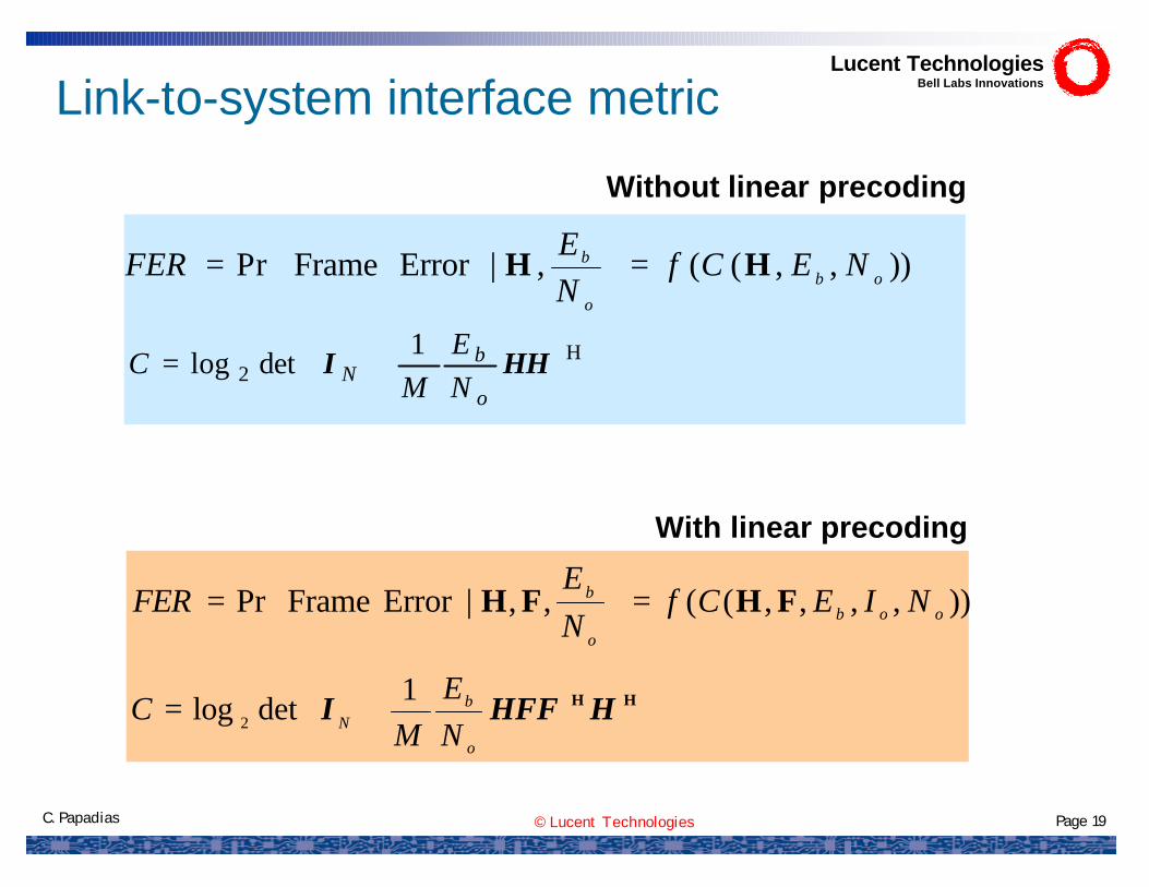
)),,((,|Error FramePr ob
o
b NECfNE
FER HH =
=
+= H
21
detlog HHIo
bN N
EM
C
Link-to-system interface metric
)),,,,((,,|Error FramePr oob
o
b NIECfNE
FER FHFH =
=
+= HH HHFFI
o
bN N
EM
C 1detlog 2
Without linear precoding
With linear precoding
Lucent TechnologiesBell Labs Innovations
© Lucent Technologies Page 20C. Papadias
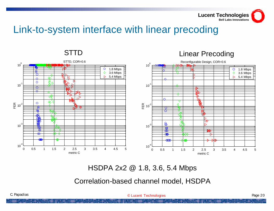
Link-to-system interface with linear precoding
0 0.5 1 1.5 2 2.5 3 3.5 4 4.5 510
-4
10-3
10-2
10-1
100
STTD, COR=0.6
metric C
FE
R
1.8 Mbps3.6 Mbps5.4 Mbps
0 0.5 1 1.5 2 2.5 3 3.5 4 4.5 510
-4
10-3
10-2
10-1
100 Reconfigurable Design, COR=0.6
metric C
FE
R
1.8 Mbps3.6 Mbps5.4 Mbps
HSDPA 2x2 @ 1.8, 3.6, 5.4 Mbps
Correlation-based channel model, HSDPA
STTD Linear Precoding
Lucent TechnologiesBell Labs Innovations

© Lucent Technologies Page 21C. Papadias
Link-to-System Interface for WLAN
( )( )( )∑=
−+=K
kkkkw
Hk
Hk C
KC
1
1detlog1
FHHFI
Capacity
( )( ) ( )( )∑ ∑=
−−−
−=
−K
kQKo
kk
kkkkkwH
kkkkM eR
1 ˆ,
ˆˆ12
11
41
2logcc
ccFHCccFH
Cut-off Rate
For the transmission schemes and scenarios considered in FITNESS
the two metrics are nearly the same.
For other transmission schemes or scenarios
the cut-off rate may provide a lower dispersion in the
mapping.
QPSK 4x454Mbps
QPSK 2x224Mbps
PE
R
QPSK 4x454Mbps
QPSK 2x224Mbps
PE
RP
ER
QPSK 4x424Mbps
QPSK 4x424Mbps
PE
R
Lucent TechnologiesBell Labs Innovations
© Lucent Technologies Page 22C. Papadias
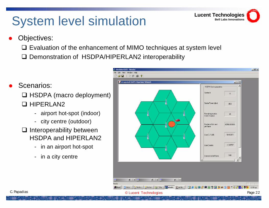
System level simulation
l Scenarios:q HSDPA (macro deployment)q HIPERLAN2
- airport hot-spot (indoor)- city centre (outdoor)
q Interoperability between HSDPA and HIPERLAN2
- in an airport hot-spot
- in a city centre
Lucent TechnologiesBell Labs Innovations
l Objectives:q Evaluation of the enhancement of MIMO techniques at system levelq Demonstration of HSDPA/HIPERLAN2 interoperability

© Lucent Technologies Page 23C. Papadias
HSDPA simulation assumptions
STTD, Reconfigurable SchemeTransmission Schemes
Low mobility + vehicular speedsMobility
Web browsing (64kbps, SAF=0.6)FTP (384kbps, SAF=0.4)
Services
3 Mbps, 6 Mbps, 9 MbpsTraffic load per sector
1.8 Mbps, 3.6 Mbps, 5.4 Mbps, 10.8 MbpsTransmission rates for SISO and MIMO 2X2
Link–system interface
Geometry Based stochastic model Fast fading MIMO channel
Antenna pattern
8 dBLog-normal shadowing
Propagation model
1400mRadius
Three sectored, hexagonal cellsShape
19Num of cells
1034.5 35log ( )PL d= +
⋅⋅+= H
21
detlog HHIo
bN N
EM
SFC
( ) 180180 where ,12min2
3
≤≤−
−= θ
θθθ m
dB
AA
Lucent TechnologiesBell Labs Innovations

© Lucent Technologies Page 24C. Papadias
Hiperlan2 simulation assumptions
SVD-based reconfigurable schemeTransmission Schemes
SISO : 6, 12, 18, 27 (Mbps)MIMO 2X2: 12, 18, 27, 36 (Mbps)MIMO 4X4: 27, 36, 54 (Mbps)
Traffic load per AP
Web browsing (64kbps, SAF=0.4)FTP (384kbps, SAF=0.6)Services
SISO : 6, 12, 18 (Mbps)MIMO 2X2: 6, 12, 24, 36 (Mbps)MIMO 4X4: 24, 36, 54 (Mbps)
Transmission rates
3 km/h (outdoor), 1.8 km/h (indoor)Mobility
Link –system –interface
correlation-based stochastic channel modelFast fading MIMO channel
Omni directional Antenna pattern
8 dB (indoor), 10dB (outdoor)Log-normal shadowing
PL = 46.7+24log10d+S (indoor)PL= 46.7+20log10d+a.d+S (outdoor)
Propagation model
16 square cells, range: 70 mDeployment
( )( )( )∑=
−+=K
kkkk
Hk
HkK
C1
1detlog1
FHRHFI
Lucent TechnologiesBell Labs Innovations

© Lucent Technologies Page 25C. Papadias
HSDPA system-level simulation results
PDF of Users (Relative) Allocated RateSISO MIMO 2X2
Traffic Load: 6 Mbps/sector- web users/sector = 56 - FTP users/sector = 6
15.2% 22.32%
Lucent TechnologiesBell Labs Innovations

© Lucent Technologies Page 26C. Papadias
MIMO 4X4MIMO 2X2
Traffic Load: 27 Mbps/AP- web users/AP = 169 - FTP users/AP = 42
PDF of Users (Relative) Allocated Rate
27.62% 78.38%
Lucent TechnologiesBell Labs Innovations
69.35%
Hiperlan2 system-level simulation results
SISO

© Lucent Technologies Page 27C. Papadias
Satisfied users in airport interoperability scenario
HSDPA 2X2Load=6Mbps/sector
Stand-aloneInteroperability 49.8% 22.32%
Lucent TechnologiesBell Labs Innovations

© Lucent Technologies Page 28C. Papadias
Wireless World Research Forum (WWRF)Major objectives:
q to develop and maintain a consistent vision of the Wireless Worldq to generate, identify, and promote research areas and technical and society
trends, including new technologies, for mobile and wireless systems towards a Wireless World
q to contribute to the definition of international and national research programs
Scope:
q concentrate on the definition of research items relevant to the future of mobileand wireless communications, including pre-regulatory impact assessments
q WWRF is not a standardization bodyq Invites world-wide participation and is open to all players
6 working groups:Ø WG1 - Business Models and End User Aspects
Ø WG2 - Service Platform Architectures
Ø WG3 - Heterogeneous networks (interworking)
Ø WG4 – New radio interfaces, relay based systems and smart antennas*
Ø WG5 – Short-range radio communication systems
Ø WG6 – Reconfigurability
Lucent TechnologiesBell Labs Innovations
Web site: http://www.wireless-world-research.org
* See, e.g. A. Alexiou and M. Haardt, ‘‘Smart Antenna Technologies for Future Wireless Systems: Trends and Challenges,’’ to appear, IEEE Communications Magazine.
© Lucent Technologies Page 29C. Papadias
l Goal:To improve the QoS (throughput and delay)
on the downlink of packet data systems (using multiple base station antennas)
l In doing so, stay as backward compatible to existing systems as possible, i.e.:
– Single antenna terminals– Standard rate feedback per terminal– Minimal changes to the terminal, simple changes at the base
l Solution is based on original idea of opportunistic beamformingl Submitted as contribution in WWRF’s Working Group 4:
Lucent TechnologiesBell Labs Innovations
Jointly Opportunistic Beamforming and Scheduling (JOBS) for downlink packet access
‘‘Duplexing, Resource Allocation and Inter-cell Coordination-Design Recommendations for Next Generation Systems,’’ WG4 White Paper.
© Lucent Technologies Page 30C. Papadias
Opportunistic Beamforming (OBF), proposed in 2002* amounts to replacing the BS antenna with multiple antennas, used as follows:
The BS generates a single beam that repetitively scans the cell/sector, progressing with a fixed angular step at the beginning of each timeslot
Main features:– Simplicity and robustness– Like OS, OBF requires the same small amount of uplink feedback.– The beam generation algorithm runs independently of the scheduler– Performance:
The standard OBF algorithm improves the system throughput, however it may still admit significant delays
Opportunistic Beamforming: background
* P. Viswanath, D. Tse, R. Laroia, “OpportunisticBeamforming using Dumb Antennas”, IEEE Trans. Inf. Theory, June 2002.
Lucent TechnologiesBell Labs Innovations

© Lucent Technologies Page 31C. Papadias
JOBS*: an improved OBF algorithm
We propose a novel OBF scheduler that combines the PF algorithm with a simple “beam generating” algorithm thatattempts to adjust priorities based on waiting times.
Ø The PF algorithm runs as is for scheduling
Ø The key idea is to point the beam toward mobiles “waiting longer,” thus improving the delay outage statistics
*D. Avidor, J. Ling, C. Papadias, ‘‘Jointly Opportunisitic Beamforming and Scheduling for Downlink Packet Access,’’ International Conference on Communications (ICC-2004),
Paris, France, June 20-24, 2004.
Lucent TechnologiesBell Labs Innovations

© Lucent Technologies Page 32C. Papadias
-10 -5 0 5 10 15 200
0.2
0.4
0.6
0.8
1
SIR (dB)
Pr(
SIR
< x
-axi
s)System-level simulation
Random mobile locations
2 rings of interfering cells
Base transmits continuously
Distance dependent pathloss exponent 3.5, lognormal shadowfade 8 dB
Thermal noise neglected
CDF of SNR over 120deg. sector
Lucent TechnologiesBell Labs Innovations

© Lucent Technologies Page 33C. Papadias
System Throughput vs. Delay Outage
.
Lucent TechnologiesBell Labs Innovations

© Lucent Technologies Page 34C. Papadias
Lucent TechnologiesBell Labs Innovations•
Wireless world INitiative NEw Radio: WINNER
The prime air interface Integrated Project of FP6
Partners:
Manufacturers: Siemens AG Co-ordinator (Germany), Alcatel SEL AG (Germany), Elektrobit Ltd (Finland), Ericsson AB (Sweden), Ericsson Eurolab Deutschland GmbH (Germany), Fujitsu Laboratories of Europe Ltd (UK), Lucent Technologies Network Systems UK Ltd (UK), Motorola S.A.S. (France), Nokia Corporation (Finland), Philips Electronics UK Limited (UK), Samsung Electronics UK Ltd (UK), Siemens Mobile Communications SPA (Italy), Siemens Aktiengesellschaft Österreich (Austria), Nokia (China) Investment Co., Ltd. (PR China)Network operators: DoCoMo Communications Laboratories Europe GmbH (Germany), European Institute for Research and Strategic Studies in Telecommunications GmbH (Germany), France Telecom S.A. (France), Portugal Telecom Inovação S.A. (Portugal), Telefónica Investigación y Desarrollo Sociedad An ónima Unipersonal (Spain), Vodafone Group Services Ltd (UK)Universities: Aalborg University (Denmark), Carleton University (Canada), Chalmers University of Technology (Sweden), Helsinki University of Technology (Finland), Kungl Tekniska Högskolan (Royal Institute of Technology) –KTH (Sweden), National Technical University of Athens (Greece), Poznan University of Technology (Poland), Rheinisch-Westfaelische Technische Hochschule Aachen (Germany), Swiss Federal Institute of Technology Zurich (Switzerland), Technische Universität Dresden (Germany), Technische Universität Ilmenau (Germany), University of Oulu-CWC(Finland),The University of Surrey (UK)Research Centers: Centre Technològic de Telecomunicacions de Catalunya (Spain), China Academy of Telecommunication Research (PR China), Deutsches Zentrum für Luft- und Raumfahrt e.V. (Germany), Technical Research Centre of Finland VTT (Finland)
Task 2.5: “Advanced (Multi) Antenna Concepts for Future Broadband Radio Interface”
•
Wireless world INitiative NEw Radio: WINNER
The prime air interface Integrated Project of FP6
Partners:
ManufacturersManufacturers: : Siemens AGSiemens AG CoCo--ordinatorordinator (Germany)(Germany), , Alcatel SEL AG (Germany),Alcatel SEL AG (Germany), ElektrobitElektrobit Ltd (Finland), Ericsson Ltd (Finland), Ericsson AB (Sweden), EricssonAB (Sweden), Ericsson EurolabEurolab Deutschland GmbH (Germany), Fujitsu Laboratories of Europe Ltd Deutschland GmbH (Germany), Fujitsu Laboratories of Europe Ltd (UK), Lucent (UK), Lucent Technologies Network Systems UK Ltd (UK), Motorola S.A.S. (FrancTechnologies Network Systems UK Ltd (UK), Motorola S.A.S. (France), Nokia Corporation (Finland), Philips e), Nokia Corporation (Finland), Philips Electronics UK Limited (UK), Samsung Electronics UK Ltd (UK), SiElectronics UK Limited (UK), Samsung Electronics UK Ltd (UK), Siemens Mobile Communications SPA (Italy), emens Mobile Communications SPA (Italy), SiemensSiemens Aktiengesellschaft Aktiengesellschaft ÖÖsterreichsterreich (Austria), (Austria), Nokia (China) Investment Co., Ltd. (PR China)Nokia (China) Investment Co., Ltd. (PR China)Network operatorsNetwork operators: : DoCoMoDoCoMo Communications Laboratories Europe GmbH (Germany), European InsCommunications Laboratories Europe GmbH (Germany), European Institute for titute for Research and Strategic Studies in Telecommunications GmbH (GermaResearch and Strategic Studies in Telecommunications GmbH (Germany), France Telecom S.A. (France), Portugal ny), France Telecom S.A. (France), Portugal Telecom Telecom InovaInovaçãçãoo S.A. (Portugal), S.A. (Portugal), TelefTelefóónica Investigacinica Investigacióónn y y Desarrollo Sociedad AnDesarrollo Sociedad An óónima Unipersonalnima Unipersonal (Spain), (Spain), Vodafone Group Services Ltd (UK)Vodafone Group Services Ltd (UK)UniversitiesUniversities:: AalborgAalborg University (Denmark), Carleton University (Canada), Chalmers UnUniversity (Denmark), Carleton University (Canada), Chalmers University of Technology iversity of Technology (Sweden), Helsinki University of Technology (Finland), (Sweden), Helsinki University of Technology (Finland), Kungl Tekniska HKungl Tekniska Höögskolangskolan (Royal Institute of Technology) (Royal Institute of Technology) ––KTH (Sweden), National Technical University of Athens (Greece), KTH (Sweden), National Technical University of Athens (Greece), PoznanPoznan University of Technology (Poland), University of Technology (Poland), RheinischRheinisch--Westfaelische Technische Hochschule AachenWestfaelische Technische Hochschule Aachen (Germany), Swiss Federal Institute of Technology Zurich (Germany), Swiss Federal Institute of Technology Zurich (Switzerland), (Switzerland), Technische UniversitTechnische Universitäätt Dresden (Germany), Dresden (Germany), Technische UniversitTechnische Universitäät Ilmenaut Ilmenau (Germany), University of (Germany), University of OuluOulu--CWC(Finland),The University of Surrey (UK)CWC(Finland),The University of Surrey (UK)Research CentersResearch Centers: : Centre Centre TechnolTechnolòògicgic de de TelecomunicacionsTelecomunicacions de de CatalunyaCatalunya (Spain), China Academy of (Spain), China Academy of Telecommunication Research (PR China), Telecommunication Research (PR China), Deutsches Zentrum fDeutsches Zentrum füür Luftr Luft-- und und RaumfahrtRaumfahrt e.V. (Germany), Technical e.V. (Germany), Technical Research Centre of Finland VTT (Finland)Research Centre of Finland VTT (Finland)
Task 2.5: “Advanced (Multi) Antenna Concepts for Future Broadband Radio Interface”
[http://www.ist-winner.org]

© Lucent Technologies Page 35C. Papadias
T2.5 Advanced Multi-Antenna Concepts
l Scenarios and Network Topology
l Duplexing Scheme
l Basic Transmission Scheme
l Mobility and Degree of Channel Knowledge
l SIMO/MISO/MIMO Signal Processing
l Single- vs. Multi-User Signal Design
l Optimization Criteria and/or Overall Goal
l Supporting Functions for Link Adaptation
l RRM and MAC/DLC Protocol Issues
l Multi-user MIMO information theory
l Link and system level simulation methodology (lead by Lucent)
Lucent TechnologiesBell Labs Innovations

© Lucent Technologies Page 36C. Papadias
l An FP6 Specific Targeted Research Project (STREP)
l Objectives:– Privately-owned WLANs and broadband access lines are made
available for public use. The owners (hosts) continue to use their WLANs as usual, while casual passing users (visitors) are also allowed access to the wireless access points
– Visitors and hosts share the capacity of wireless LANs and access lines according to a general service agreement between users andthe network operator
l Logistics: 14 partners, 3 years, started In Jan 2004
l Web site: www.ist-oban.org
Multiple Antenna Techniques for Open Broadband Access Networks (OBAN)
Lucent TechnologiesBell Labs Innovations

© Lucent Technologies Page 37C. Papadias
Typical OBAN (residential) scenario
Residential Property
IndoorAP
Host UserTerminal
Interferer
Visiting UserTerminal
Visiting UserTerminal
LOS
LOS
NLOSLOS
Regular residential WLAN system:• Indoor AP, User Terminal and Interferer are privately owned • Co-existence is a local problemOBAN system:• Private indoor AP becomes OBAN AP• Co-existence is a common problem
Lucent TechnologiesBell Labs Innovations
© Lucent Technologies Page 38C. Papadias
WP1 – Scenarios & Requirements (16 MM).
WP2 – Open Access Environment Architecture (241 MM).Mobility, QoS, Security, OAN Architecture, Terminals. (Lucent is WP Leader)
WP3 – Prototyping & Integration (262 MM).Residential gateway, Terminal, Personal QoS Profile Server, Interoperability, Service Demos.(Lucent is is contributor)
WP4 – Network Coverage (142 MM).Radio Performance & Coverage, Adaptive Coding-Modulation, Antenna Technologies. (Bell Labs Wireless Research is contributor)
WP5 – Society Aspects (46 MM).Market Impacts, Business Models, Charging Models, Techno-Economic Evaluation.
WP6 – Dissemination of Results (62 MM).
Lucent TechnologiesBell Labs InnovationsOBAN work packages
© Lucent Technologies Page 39C. Papadias
l An FP6 Network of Excellence (NoE)
l Consortium:
– 9 Industrial (IDS, Lucent, Alcatel, France Telecom, Thales, Ericsson, SAAB Ericsson, BAE Systems, Antenna Systems Consulting)
– 9 Research Centres
–27 Universities
l Effort
– 846 person-months over 2 years (JAN04-DEC05)
– 266 Researchers, 96 PhD Students
l Total budget 5.4MEuro
Lucent TechnologiesBell Labs InnovationsAntenna Centre of Excellence (ACE)
© Lucent Technologies Page 40C. Papadias
r Lead the Smart Antenna research activities by being responsible for the technical management
r Research focusing on:§ Reconfigurable Transceivers and Jointly Optimized
MIMO§ Requirements for Multi-antenna Terminals§ System Level Reconfigurability Strategies and Cross
Layer Optimisation§ Context Aware Network Optimisation§ Smart Antenna Deployment and Business Modelling
Issues
r Members of the ACE Steering Committee responsible for the network management and the technical decisions
Lucent’s role in ACELucent Technologies
Bell Labs Innovations


![Mimo [new]](https://img.pdfslide.us/doc/110x75/58712c5f1a28abe4448b7621/mimo-new.jpg)