Embed Size (px)
Citation preview
© Copyright National University of Singapore. All Rights Reserved.
Solid State Transformers: Benefits and Challenges
A/P Sanjib Kumar PandaDepartment of Electrical and Computer Engineering
National University of Singapore
© Copyright National University of Singapore. All Rights Reserved.
Background: Grid2.0 and Solid State Transformer
Reliability Issues & Proposed Solutions
SST: Module Level Fault Detection and Localization
SST: Post-fault Restoration
SST: Alternative Converter Topologies
Conclusions
CONTENTS
2
© Copyright National University of Singapore. All Rights Reserved. 3
FUTURE GRID
EV
ECC~
~
Centralized Power PlantsUnidirectional power flowHigh inertia system
Micro grids with DGsBidirectional energy flow
Low inertia system
Industrial Loads
Commercial Loads
Renewable IntegrationLow Inertia System
AC & DC subsystem
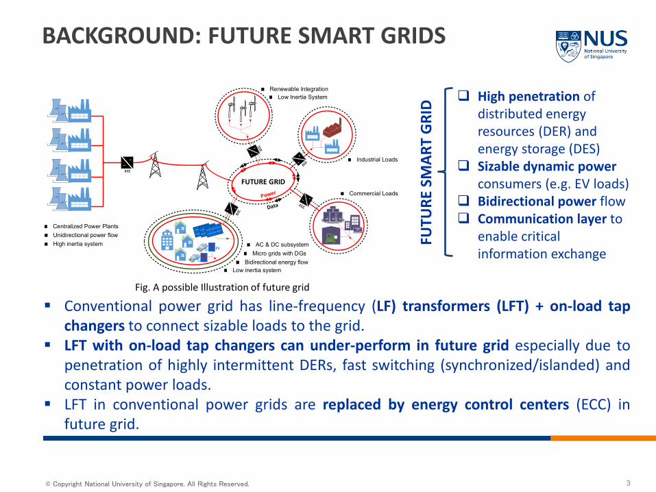
BACKGROUND: FUTURE SMART GRIDS
High penetration of distributed energy resources (DER) and energy storage (DES)
Sizable dynamic power consumers (e.g. EV loads)
Bidirectional power flow Communication layer to
enable critical information exchange
FUTU
RE S
MAR
T G
RID
Fig. A possible Illustration of future grid
Conventional power grid has line-frequency (LF) transformers (LFT) + on-load tapchangers to connect sizable loads to the grid.
LFT with on-load tap changers can under-perform in future grid especially due topenetration of highly intermittent DERs, fast switching (synchronized/islanded) andconstant power loads.
LFT in conventional power grids are replaced by energy control centers (ECC) infuture grid.
© Copyright National University of Singapore. All Rights Reserved.
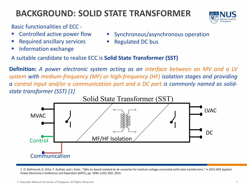
BACKGROUND: SOLID STATE TRANSFORMER
Definition: A power electronic system acting as an interface between an MV and a LVsystem with medium-frequency (MF) or high-frequency (HF) isolation stages and providinga control input and/or a communication port and a DC port is commonly named as solid-state transformer (SST) [1]
MVAC
Solid State Transformer (SST)LVAC
DCControl
Communication
MF/HF Isolation
1. D. Rothmund, G. Ortiz, T. Guillod, and J. Kolar, “10kv sic-based isolated dc-dc converter for medium voltage-connected solid-state transformers,” in 2015 IEEE AppliedPower Electronics Conference and Exposition (APEC), pp. 1096–1103, IEEE, 2015.
4
Basic functionalities of ECC - Controlled active power flow Required ancillary services Information exchange
Synchronous/asynchronous operation Regulated DC bus
A suitable candidate to realize ECC is Solid State Transformer (SST)
© Copyright National University of Singapore. All Rights Reserved.
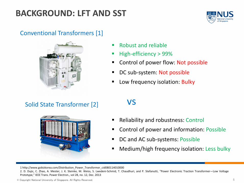
Conventional Transformers [1]
Solid State Transformer [2]
1 http://www.gobizkorea.com/Distribution_Power_Transformer_cid0801140100002. D. Dujic, C. Zhao, A. Mester, J. K. Steinke, M. Weiss, S. Lwedeni-Schmid, T. Chaudhuri, and P. Stefanutti, “Power Electronic Traction Transformer—Low VoltagePrototype,” IEEE Trans. Power Electron., vol 28, no. 12, Dec. 2013
vs
Robust and reliable
Reliability and robustness: Control
Control of power flow: Not possible
Control of power and information: Possible
DC sub-system: Not possible
DC and AC sub-systems: Possible
Low frequency isolation: Bulky
Medium/high frequency isolation: Less bulky
BACKGROUND: LFT AND SST
5
High-efficiency > 99%
© Copyright National University of Singapore. All Rights Reserved.
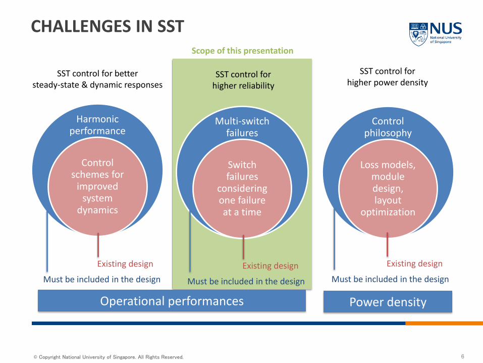
Harmonic performance
Control schemes for
improved system
dynamics
SST control for bettersteady-state & dynamic responses
Existing design
Must be included in the design
Control philosophy
Loss models, module design, layout
optimization
SST control for higher power density
Existing design
Must be included in the design
CHALLENGES IN SST
Multi-switch failures
Switch failures
considering one failure at a time
Existing design
Must be included in the design
SST control for higher reliability
Scope of this presentation
Operational performances Power density
6
© Copyright National University of Singapore. All Rights Reserved. 7
FAULT DETECTION, LOCALIZATION AND ISOLATION (FDLI) IN
SOLID STATE TRANSFORMER
© Copyright National University of Singapore. All Rights Reserved.
NEW MODEL-BASED FDLI: OVERVIEW
8
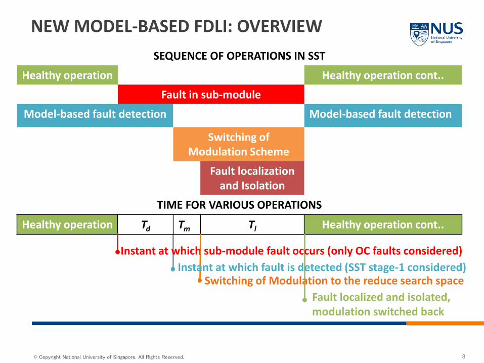
SEQUENCE OF OPERATIONS IN SST
Healthy operation Healthy operation cont..
Fault in sub-module
Model-based fault detection Model-based fault detection
Switching of Modulation Scheme
Fault localizationand Isolation
TIME FOR VARIOUS OPERATIONS
Healthy operation Td Tm Tl Healthy operation cont..
Instant at which sub-module fault occurs (only OC faults considered) Instant at which fault is detected (SST stage-1 considered)
Switching of Modulation to the reduce search spaceFault localized and isolated, modulation switched back
© Copyright National University of Singapore. All Rights Reserved. 9
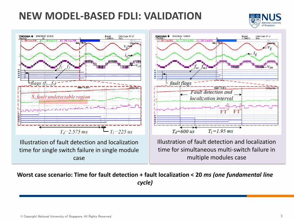
NEW MODEL-BASED FDLI: VALIDATION
Illustration of fault detection and localization time for single switch failure in single module
case
Worst case scenario: Time for fault detection + fault localization < 20 ms (one fundamental line cycle)
Illustration of fault detection and localization time for simultaneous multi-switch failure in
multiple modules case
© Copyright National University of Singapore. All Rights Reserved.
POST-FAULT RESTORATION SCHEMEFOR
SOLID STATE TRANSFORMER
10
© Copyright National University of Singapore. All Rights Reserved.
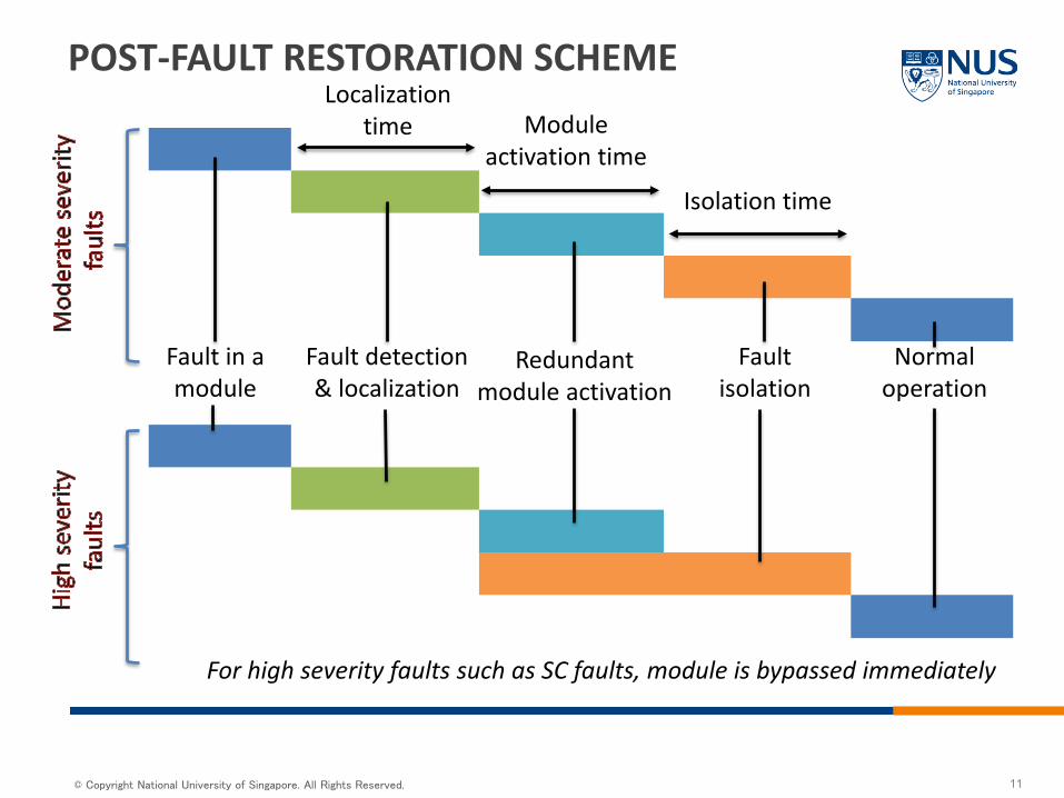
Fault in a module
For high severity faults such as SC faults, module is bypassed immediately
Fault detection & localization
Redundant module activation
Fault isolation
POST-FAULT RESTORATION SCHEME
Normaloperation
Localization time Module
activation time
Isolation time
11
© Copyright National University of Singapore. All Rights Reserved.
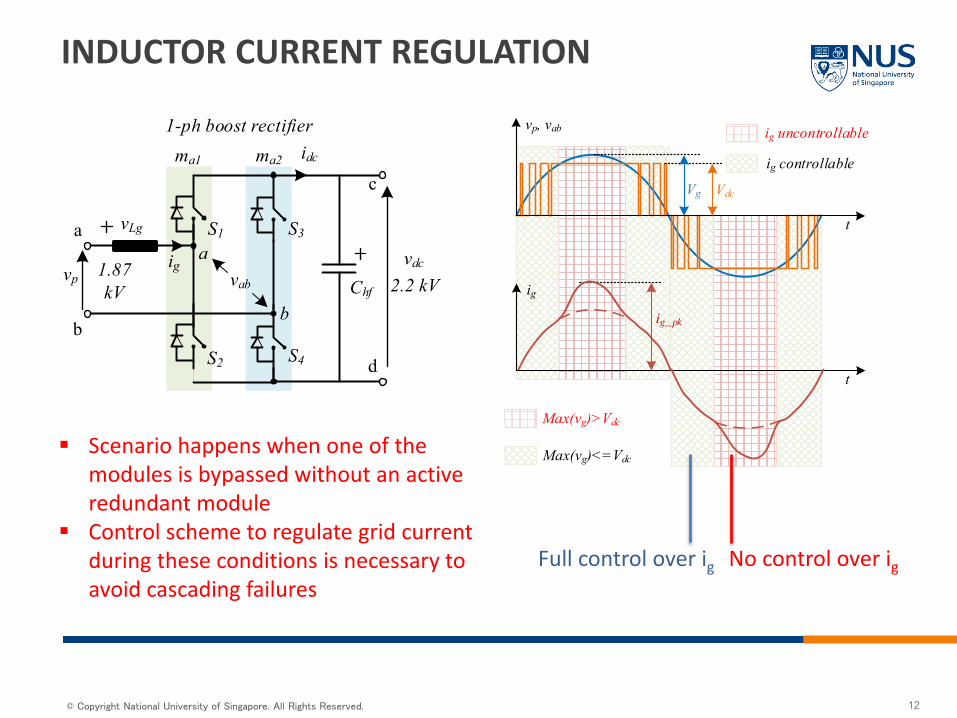
INDUCTOR CURRENT REGULATION
igvpvdc
idcma1 ma2
1-ph boost rectifier
a
b
c
d
1.87 kV 2.2 kV
S1
S2
S3
S4
vLg
Chf
a
b
vab
VdcVg
t
vp, vab
ig
ig_pk
ig uncontrollable
ig controllable
t
Max(vg)>Vdc
Max(vg)<=Vdc Scenario happens when one of the
modules is bypassed without an active redundant module
Control scheme to regulate grid current during these conditions is necessary to avoid cascading failures
Full control over ig No control over ig
12
© Copyright National University of Singapore. All Rights Reserved.
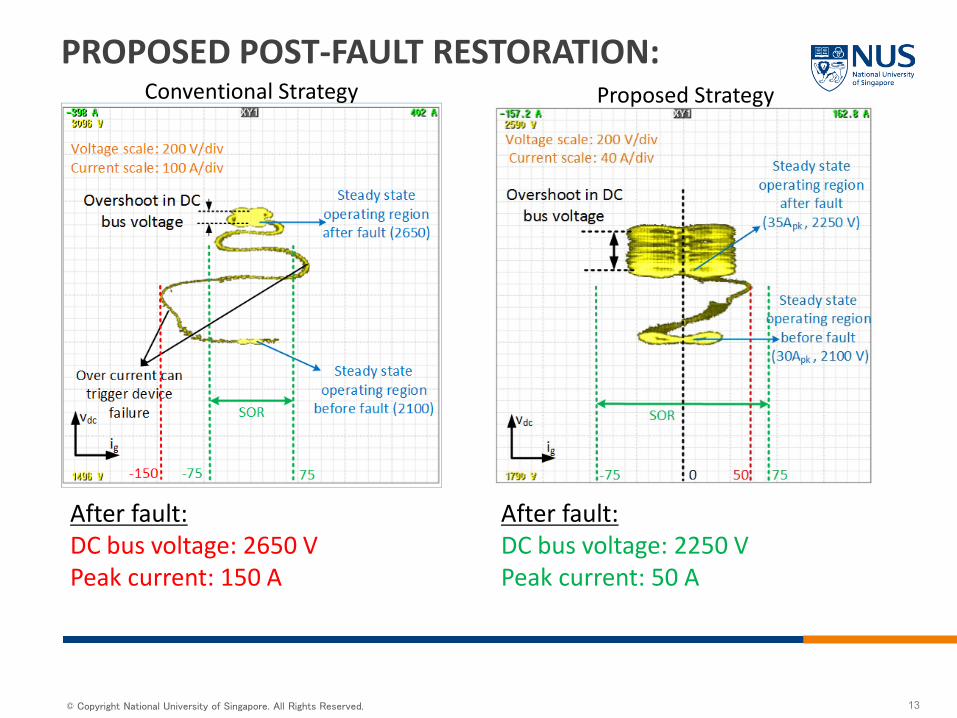
PROPOSED POST-FAULT RESTORATION:
After fault: DC bus voltage: 2650 VPeak current: 150 A
After fault: DC bus voltage: 2250 VPeak current: 50 A
13
Conventional Strategy Proposed Strategy
© Copyright National University of Singapore. All Rights Reserved.
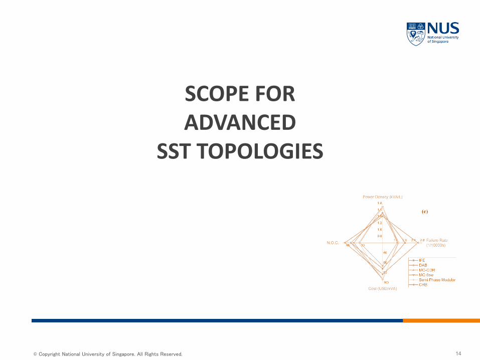
SCOPE FOR ADVANCED
SST TOPOLOGIES
14
© Copyright National University of Singapore. All Rights Reserved. 15
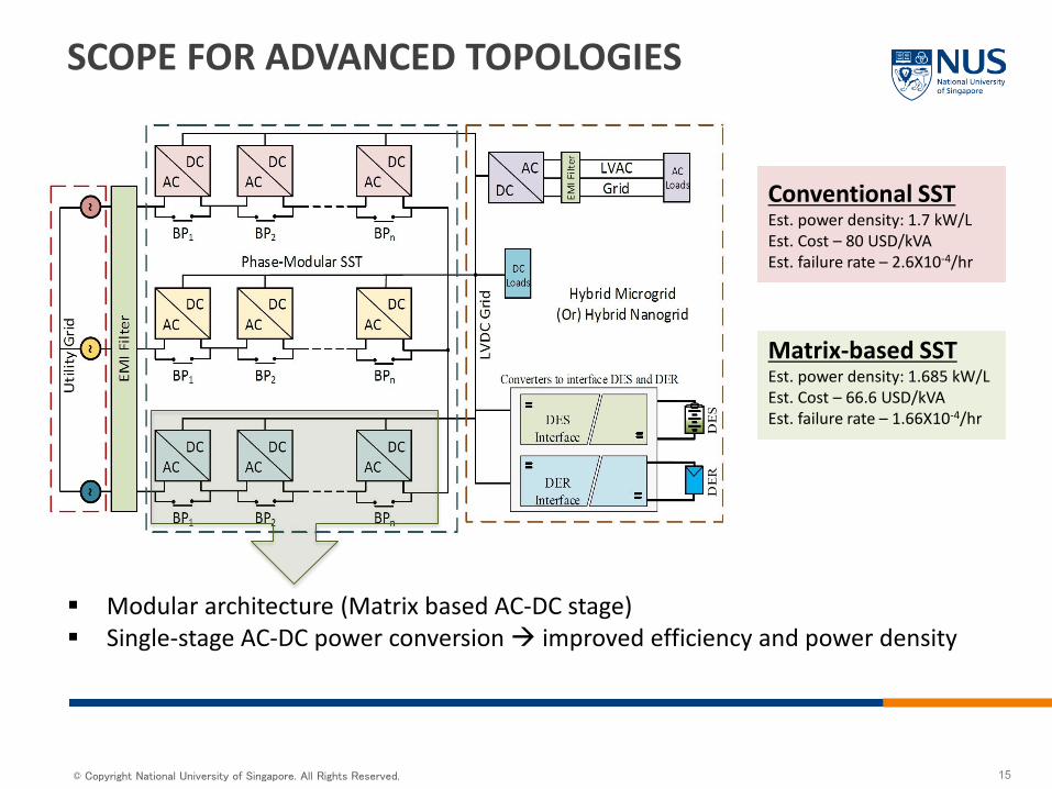
SCOPE FOR ADVANCED TOPOLOGIES
Modular architecture (Matrix based AC-DC stage) Single-stage AC-DC power conversion improved efficiency and power density
Conventional SSTEst. power density: 1.7 kW/L Est. Cost – 80 USD/kVAEst. failure rate – 2.6X10⁻⁴/hr
Matrix-based SSTEst. power density: 1.685 kW/L Est. Cost – 66.6 USD/kVAEst. failure rate – 1.66X10⁻⁴/hr
© Copyright National University of Singapore. All Rights Reserved. 16
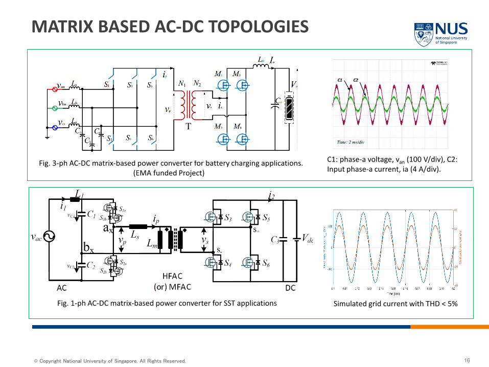
MATRIX BASED AC-DC TOPOLOGIES
Fig. 3-ph AC-DC matrix-based power converter for battery charging applications.(EMA funded Project)
Fig. 1-ph AC-DC matrix-based power converter for SST applications
C1: phase-a voltage, van (100 V/div), C2: Input phase-a current, ia (4 A/div).
Simulated grid current with THD < 5%
© Copyright National University of Singapore. All Rights Reserved. 17
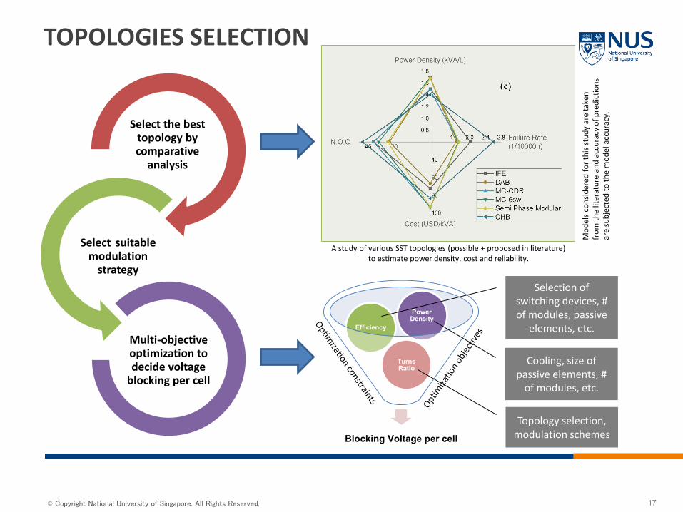
Select the best topology by comparative
analysis
Select suitable modulation
strategy
Multi-objective optimization to decide voltage
blocking per cell
Blocking Voltage per cell
Turns Ratio
Efficiency
Power Density
TOPOLOGIES SELECTION
A study of various SST topologies (possible + proposed in literature) to estimate power density, cost and reliability.
Cooling, size of passive elements, #
of modules, etc.
Selection of switching devices, # of modules, passive
elements, etc.
Topology selection, modulation schemes
Mod
els
cons
ider
ed fo
r thi
s stu
dy a
re ta
ken
from
the
liter
atur
e an
d ac
cura
cy o
f pre
dict
ions
ar
e su
bjec
ted
to th
e m
odel
acc
urac
y.
© Copyright National University of Singapore. All Rights Reserved.
SST is proposed as a possible replacement to conventional transformer in future power grid.
As an all silicon-based solution, SSTs are most prone to failures due to dynamic grid conditions.
Mechanisms to detect failures (both open-circuit and short-circuit) is a must.
Control during post-fault restoration is necessary to avoid cascading failures especially for grid applications.
Plenty of scope for further improving the power density and cost Advanced topologies
18
CONCLUSIONS
© Copyright National University of Singapore. All Rights Reserved.
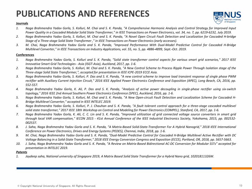
PUBLICATIONS AND REFERENCESJournals1. Naga Brahmendra Yadav Gorla, S. Kolluri, M. Chai and S. K. Panda, "A Comprehensive Harmonic Analysis and Control Strategy for Improved Input
Power Quality in a Cascaded Modular Solid State Transformer," in IEEE Transactions on Power Electronics, vol. 34, no. 7, pp. 6219-6232, July 2019.2. Naga Brahmendra Yadav Gorla, S. Kolluri, M. Chai and S. K. Panda, ”A Novel Open Circuit Fault Detection and Localization for Cascaded H-bridge
Stage of a Three-stage Solid State Transformer ," in IEEE Transactions on Power Electronics (early accesses).3. M. Chai, Naga Brahmendra Yadav Gorla and S. K. Panda, "Improved Performance With Dual-Model Predictive Control for Cascaded H-Bridge
Multilevel Converter," in IEEE Transactions on Industry Applications, vol. 55, no. 5, pp. 4886-4899, Sept.-Oct. 2019.
Conferences1. Naga Brahmendra Yadav Gorla, S. Kolluri and S. K. Panda, "Solid state transformer control aspects for various smart grid scenarios," 2017 IEEE
Innovative Smart Grid Technologies - Asia (ISGT-Asia), Auckland, 2017, pp. 1-6.2. Naga Brahmendra Yadav Gorla, S. Kolluri, M. Chai and S. K. Panda, "A New Control Scheme to Process Ripple Power Through Isolation stage of the
Three-stage Solid State Transformer,", accepted for presentation in IEEE ICPE-2019 ECCE Asia.3. Naga Brahmendra Yadav Gorla, S. Kolluri, P. Das and S. K. Panda, "A new control scheme to improve load transient response of single phase PWM
rectifier with Auxiliary Current Injection Circuit," 2016 IEEE Applied Power Electronics Conference and Exposition (APEC), Long Beach, CA, 2016, pp.552-557.
4. Naga Brahmendra Yadav Gorla, K. Ali, P. Das and S. K. Panda, "Analysis of active power decoupling in single-phase rectifier using six-switchtopology," 2016 IEEE 2nd Annual Southern Power Electronics Conference (SPEC), Auckland, 2016, pp. 1-6.
5. Naga Brahmendra Yadav Gorla, S. Kolluri, M. Chai and S. K. Panda, ”A New Open-circuit Fault Detection and Localization Scheme for Cascaded H-Bridge Multilevel Converter," accepted in IEEE INTELEC 2019.
6. Naga Brahmendra Yadav Gorla, S. Kolluri, P. J. Chauhan and S. K. Panda, "A fault tolerant control approach for a three-stage cascaded multilevelsolid state transformer," 2017 IEEE 18th Workshop on Control and Modeling for Power Electronics (COMPEL), Stanford, CA, 2017, pp. 1-6.
7. Naga Brahmendra Yadav Gorla, K. Ali, C. C. Lin and S. K. Panda, "Improved utilization of grid connected voltage source converters in smart gridthrough local VAR compensation," IECON 2015 - 41st Annual Conference of the IEEE Industrial Electronics Society, Yokohama, 2015, pp. 002532-002537.
8. J. Saha, Naga Brahmendra Yadav Gorla and S. K. Panda, "A Matrix-Based Solid-State-Transformer For A Hybrid Nanogrid," 2018 IEEE InternationalConference on Power Electronics, Drives and Energy Systems (PEDES), Chennai, India, 2018, pp. 1-6.
9. M. Chai, Naga Brahmendra Yadav Gorla and S. K. Panda, "Dual-Model Predictive Control for Cascaded H-Bridge Multilevel Active Rectifier with DCVoltage Balancing in a Solid-State Transformer," 2018 IEEE Energy Conversion Congress and Exposition (ECCE), Portland, OR, 2018, pp. 5657-5663.
10. J. Saha, Naga Brahmendra Yadav Gorla and S. K. Panda, "A Review on Matrix-Based Bidirectional AC-DC Conversion for Modular SSTs” accepted forpresentation in INTELEC 2019.
Patents1. Jaydeep saha, National university of Singapore 2019, A Matrix Based Solid State Transformer for a Hybrid Nano grid, 10201811326W.
19
© Copyright National University of Singapore. All Rights Reserved.
THANK YOU
Acknowledgements:
Dr. Naga Yadav, Dr. Amit Kumar Singh, Mr. Prathamesh Deshmukh, Mr. Hua Chong Aih and Mr. Jaydeep Saha

© Copyright National University of Singapore. All Rights Reserved. 21