Embed Size (px)
Citation preview
7/28/2019 solar salt
http://slidepdf.com/reader/full/solar-salt 1/27
DESIGN & LAYOUT OF SOLAR SALT WORKS
Dr. M J. Mehta,
Delivered lecture in Training course cum Seminar in Salt Technology
at Madras, 4 – 22 August 1981
1 DESIGN & LAYOUT:
The process of obtaining common salt and other marine chemicals which are dissolved
in sea water or natural brine is entirely by gradual evaporation and fractional separation
of solids at different densities (concentration). The method by which common salts isproduced by solar evaporation is very much practiced in our country even before the
chemistry of salt was established. This method is utilized to different degree depending
upon the prevailing climatic conditions, the geographical location of the source and the
advancement of technical knowledge and its application. In western hemisphere where
prolonged dry weather is uncommon, solar evaporation of either sea water or natural
brine is not so feasible and salt is produced by dry mining of salt deposits or by artificial
Evaporation of brine in tropical country like India, where long dry weather exists,
manufacture of salt by solar evaporation is adopted, and salt of very good quality &quantity has been produced. The design of solar salt works has remained a rule of
thumb by the persons experienced in salt manufacture as the demand for salt has
increased due to growing population & industrial consumption.
The greater purity & more yield per acre has become more important. Hence, it has
become necessary to apply more basic data of evaporation of brine, soil characteristic,
climatic conditions, etc. for the layout of salt works.
2 DESIGN AND LAYOUT OF SALT WORKS IN INDIA:
(1) Steps involved in establishment of a salt work: The main operations involved in the
manufacture of salt are evaporation and crystallization depending on the solubility
relations of the constituents of sea water. The design of a solar salt work is primarily
aimed at accomplishment of these operations in a most efficient manner, and calls for an
7/28/2019 solar salt
http://slidepdf.com/reader/full/solar-salt 2/27
experience in the various engineering aspects of salt manufacture. The different steps
involved in establishment of a salt work in order of their priority are:
1. Selection of a suitable site;
2. Designing the layout; and
3. Construction of the salt work as per design.
3 FACTORS AFFECTING DESIGN:
1 Selection of a suitable site:
The selection of a suitable site is the most important step in the establishment of a
solar salt work as the ultimate success of the project depends on the proper decision in
this respect. This selection is influenced by the technical factors which includes the
production of salt as well by the commercial factors which include the disposal of salt in
the market. Being the cheapest commodity, a site close to the market is very much
desirable, as it helps in minimizing the cost involved in its transport. It is advantageous
to locate a salt work in the proximity of a salt based industry or where shipping and rail
transport is within reach. The next step involves in finding out the nature of soil. A soil of almost impervious nature is a major requirement. This property of soil depends on its
composition. Normally the soil near the sea coast is alluvial type and contains coarse
sand: 0.2 to 2.0mm; fine sand 0.02 to 0.2mm; silt 0.002 to 0.02 mm and clay below
0.002 mm. The fraction coarser than coarse sand is gravel having a particle size from 2
to 75 mm. Soils containing gravel and coarse sand are quite unsuitable for
establishment of a salt work as they cause considerable percolation. The percentage of
fine sand, silt and clay also varies from soil to soil and depending on these percentages
they are broadly classified into three types viz. Sandy, Loamy and Clayey and each type
is further sub classified as follows:
7/28/2019 solar salt
http://slidepdf.com/reader/full/solar-salt 3/27
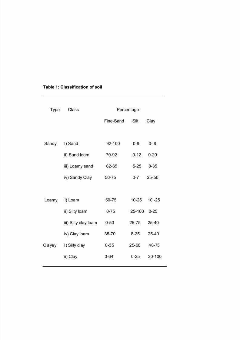
Table 1: Classification of soil
Type Class Percentage
Fine-Sand Silt Clay
Sandy I) Sand 92-100 0-8 0- 8
ii) Sand loam 70-92 0-12 0-20
iii) Loamy sand 62-65 5-25 8-35
iv) Sandy Clay 50-75 0-7 25-50
Loamy I) Loam 50-75 10-25 10 -25
ii) Silty loam 0-75 25-100 0-25
iii) Silty clay loam 0-50 25-75 25-40
iv) Clay loam 35-70 8-25 25-40
Clayey I) Silty clay 0-35 25-60 40-75
ii) Clay 0-64 0-25 30-100
7/28/2019 solar salt
http://slidepdf.com/reader/full/solar-salt 4/27
It is found that soils containing up to 60 percent of fine sand as the largest particle size
and not less than 40 percent clay and silt together afford a reasonably impervious soil.
Therefore, soils of silty clay and clay class are the most suitable for establishment of
solar salt works. The presence of fine sand in soil imparts another desirable
characteristic to it viz., increased bearing strength. The soils which can improve in
bearing strength up to 1 to 1.40 Kg per square centimeter are quite suitable. This
property of the soil makes the beds of the crystallizers sufficiently hard and do not get
damaged during salt harvesting operations either manually or by mechanical means.
In order of preference, after the clayey type of soils clay loam and silty clay loam from
among the loamy type are also useful for establishment of the salt works. The soil
should be devoid of any vegitatation as their roots in the soil cause voids through which
heavy percolation occurs.
4 AREA REQUIREMENT:
The area requirement for a solar salt work being very large, sufficient land should be
available close to the source of brine for immediate use as well as for any future
expansion. Further, the land should preferably display a gentle gradient of about 30 to
40 cm in a kilometer and be in a depression which gets inundated by the periodical
spring tidal rise to an extent of about half to one meter. This assures a continuous
adequate brine supply
5 BRINE DENSITY:
The brine density is a factor that links with the economics of salt manufacture. Since
brine requires a large area and solar energy for concentration, and which further
requires to be exposed for longer period, the lesser the concentration of the initial brine
more it is uneconomical to operate the solar salt works. The normal density of sea water
is in the vicinity of 3.5 ø Be'. But it varies depending on the location of the site. Brine
from sea coasts in the neighborhood of which rivers discharge their flood waters usually
gets diluted. Such dilution effect is observed immediately after rainy season. It then
slowly gains in density with advancement of season. It is wasteful to admit brine of the
density below 1.5 ° Be'
7/28/2019 solar salt
http://slidepdf.com/reader/full/solar-salt 5/27
.
6. EVAPORATION
Evaporation is the chief operation involved in the manufacture of salt. A number of
factors are known which affect evaporation, both meteorological and physical. These
are (1) quantity of dissolved substance or substances, (2) radiation, (3) temperature, (4)
humidity, (5) rainfall, (6) Wind, (7) depth of water mass, (8) soil colour and (9) size and
shape of water surface. Because of the complicated relationship between these various
factors, it is difficult to assess the relative importance of each individual factor and
therefore the combine effect of the influencing factors on the rate of evaporation is only
Taken in to consideration The manner in which each individual factor plays its role in
evaporation is described bellow:
7. DISSOLVED SUBSTANCE:
Since the solubility of sodium chloride is little affected with increase in temperature, it is
crystallized out from Sea Water on evaporation. The rate of evaporation and
consequently the concentration of a liquid solution depend on the quantities of
substances or substances dissolved in it. The more the quantities of dissolved
substances the lesser is the rate of evaporation. Evaporation decreases by about one
per cent for every one percent increase in salinity under identical conditions and also
simultaneously decreases with increasing evaporating area.
8. RADIATION:
The change in state of water from a liquid to a gas involves a utilization of approximately
590 calories per gram of water. Solar radiation therefore plays a considerable part and
governs the main variations in the rate of evaporation. It is now generally regarded as
the most important single factor involved.
9 TEMPERATURE:
.The air and the water temperatures are largely dependent on solar radiation. Since the
temperature of water surface governs the rate at which the water molecules leave the
surface and enter in to overlaying air, evaporation rate is increased at higher
7/28/2019 solar salt
http://slidepdf.com/reader/full/solar-salt 6/27
temperatures. The ideal range of temperature is between 20 C (min) and 45 C
(Max). Evaporation rate falls appreciably when the air temperature falls below 10 C.
10. HUMIDITY:
Humidity is an important factor. With an increase in the relative humidity the capacity of
the atmosphere to take up more water vapour from the evaporating body decreases.
The regions in which the relative humidity prevails at low value are more suitable for
establishment of salt works. The evaporation particularly ceases to take place when the
relative humidity exceeds 80%. Relationship exists between solar energy, radiation,
temperature, humidity and evaporation.
11. RAINFALL:
The progress and the net evaporation rate in a particular area depend on the total and
distribution rainfall during the year. To operate a successful solar salt works, it is
essential that the annual rainfall should be as low as possible and its distribution
restricted too few months leaving longer clear weather duration for salt manufacture. The
area receiving not exceeding 600 mm of rainfall in a total spell of 100 days are
considered most suitable for establishment of salt works. Solar salt plants can be
successfully operated in areas even where the total annual rain fall is to an extent of
1600 mm but which is restricted to a definite duration of rainy season. Occasional
showers not exceeding 15 to 20 mm in any one spell of 24 hours do not deter the salt
manufacturing operations.
12. WIND VELOCITY:
Wind helps in removal of the air saturated with water vapour from the surface of the
evaporating body and bringing in contact with it fresh unsaturated layer of the
atmosphere thus increasing evaporation. Such an increase in evaporation with wind
speed is observed up to a certain critical value and any further increase in the wind
speed does not further enhance the evaporation. A desirable range of wind speed which
aids evaporation is from 3 Km to 15 Km per hour.
7/28/2019 solar salt
http://slidepdf.com/reader/full/solar-salt 7/27
The direction of the wind is an equally important consideration as its speed. The wind
blowing from over the sea is normally saturated with water vapour and is incapable of
taking fresh water vapour, thus reducing evaporation. Wind blowing from over the land is
dry and can take up water vapour till it attains saturation and thus aids evaporation.
The direction of the wind therefore plays its own part... Usually wind blowing from NE
and NW direction in India in very much useful in enhancing the rate of evaporation. The
direction of the wind prevailing for most of the period of salt manufacture is made use of
while laying evaporating ponds and more particularly the crystallizers.
13. PERCOLATION:
Brine percolation from reservoir, condensers and crystallizers is one of the major factors
which should not be ignored in designing the solar salt works. Because it affect the
production and economic of unit The majority of the soil near the sea coast is alluvial in
nature showing strong stratification. This property makes exact measurement of
percolation. This property makes exact measurement of percolation very difficult. But a
designer with some broad guidelines should be able to design a fairly reasonable plan.
Typical Permeability Values
The classification of soil on the bases of permeability is given below which is derived
from a table by Terzaghi and Peck (1948) Classification of soil according to
permeability is given below
Table 2: Permeability of soil by Terzaghi (1948)
Degree of Permeability Range of coefficient of permeability,
‘K’ (m / s)
High Greater then 10 Exp -3
Medium 10 Exp -3 to 10 Exp -5
Low 10 Exp -5 to 10 Exp -7
Very Low 1- Exp -7 to 10 Exp -9
7/28/2019 solar salt
http://slidepdf.com/reader/full/solar-salt 8/27
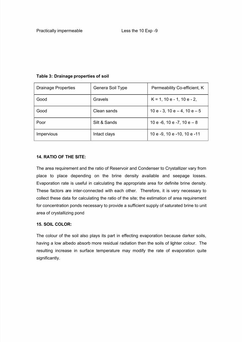
Practically impermeable Less the 10 Exp -9
Table 3: Drainage properties of soil
Drainage Properties Genera Soil Type Permeability Co-efficient, K
Good Gravels K = 1, 10 e - 1, 10 e - 2,
Good Clean sands 10 e - 3, 10 e – 4, 10 e – 5
Poor Silt & Sands 10 e -6, 10 e -7, 10 e – 8
Impervious Intact clays 10 e -9, 10 e -10, 10 e -11
14. RATIO OF THE SITE:
The area requirement and the ratio of Reservoir and Condenser to Crystallizer vary from
place to place depending on the brine density available and seepage losses.
Evaporation rate is useful in calculating the appropriate area for definite brine density.
These factors are inter-connected with each other. Therefore, it is very necessary to
collect these data for calculating the ratio of the site; the estimation of area requirement
for concentration ponds necessary to provide a sufficient supply of saturated brine to unit
area of crystallizing pond
15. SOIL COLOR:
The colour of the soil also plays its part in effecting evaporation because darker soils,
having a low albedo absorb more residual radiation then the soils of lighter colour. The
resulting increase in surface temperature may modify the rate of evaporation quite
significantly.
7/28/2019 solar salt
http://slidepdf.com/reader/full/solar-salt 9/27
16. SIZE AND SHAPE OF WATER SURFACE:
The relationship between the size of evaporating water surface and the rate of
evaporation was first study by Tomlison. It is observed that evaporation from open water
surface decreases with increasing area. The reasons for this phenomenon can be
explained with Dalton equation, who suggested that if other factors remain constant,
evaporation is proportional to the wind speed and the vapour pressure deficit, i.e.
the difference between the saturation vapour pressure at the temperature of water
surface and the actual vapour pressure of the overlying air. In practice the rate of
evaporation can be directly measured by using U.S. Weather Bureau Standard "A" pan
evaporimeter. It is a circular tank 120 cm diameter and 25 cm deep. A still well is placed
in the tank to maintain still water surface and to support the hook-gauge for accurate
measurements. The still well consists of an iron triangular base with leveling screws. A
pipe of about 9 cm diameter is fixed to the base.
The bottom of the pipe is closed leaving a small hole for the entry of water. Water is filled
in the pan to a depth of 20cm. Daily fall in water level is recorded with the help of a hook-
gauge. Evaporation rates thus obtained are higher than actual rates from the larger
bodies of water because of smaller area of the evaporation and therefore need
correction. The correction factor varies with location, climate and season and ranges
between 0.65 to 0.77
17. PLANING THE DESIGN AND LAYOUT OF SALT WORKS:
Once the site for establishment of a salt work is selected, from the best compromise of
several ideal factors. The next step rests in carefully preparing a layout which can fetch
the maximum advantage of the climatic and other parameters prevailing in the locality
which affect the yield of salt per unit area, its collection storage and transport for ultimate
disposal in the market. The basic principal to be followed in planning and designing a
salt work is to obtain economic production by keeping the manufacturing cost as low as
possible. The first step in designing of a salt work is to decide the proper selective
locations of the different components. Under the ideal conditions the total brine
7/28/2019 solar salt
http://slidepdf.com/reader/full/solar-salt 10/27
requirement is obtained through sluice gates at the time of spring tides is flown by
gravity to the process areas and crystallizers without any aid of pumping. In the absence
of such ideal conditions one has to make use of the contours of the land available and
design the layout in a way that the flow of brine is regulated by gravity as far as possible
and pumping is resorted to at minimum stages. Levels and surrounding contours of
ground vis-à-vis the sea and its tidal rise have to be perfectly known before finalizing the
site for reservoir and that of intake gates known as sluice gates. Usually the contour
levels are noted at every 60 meters distance in relation to a fixed bench mark. The
difference between the readings in relation to the bench mark and that as per tidal rise
above the mean sea level 9 M.S.K. as predicted in the tide tables is noted at some
convenient points and the readings of levels are then converted in relation to mean sea
level. This affords direct relation between the tidal rise and the contours of the land.
18. SLUICE GATES FOR SEA WATER INTAKE:
In salt works, normally, following types of sluice gates are used for taking sea brine in to
reservoir, during high tides,
(1) Automatic sluice gates (2) Lifting type
In addition to above types of gates, box type of gates with Lifting gates to be
manually, are used extensively to regulate the flow of brine to one compartment
of condenser to another. The use of such gate is simple and not expensive. As an
alternate Hume pipes of suitable size with suitable regulating arrangement for
the flow of brine , can also be used, with advantage automatic sluice gates. It is
misnomer to call these type of gates as automatic type of gates as these do not
work automatically, however, such type of gates eliminates to great extent,
human factor in admitting brine on high tide in to reservoir, as compare to lifting
type of gates, at the same time, there are certain disadvantage of such types of
gates is that the tide water can not availed of to any limited extent if tidal rise
goes above the level of brine in reservoir close down when the level of brine
in creek has gone down.
Secondly these gates are only in one way in letting in the brine and no quantity
of brine can be drained out of reservoir through these gates in case the bunds
are threatening or similar other emergency. Some improvements have been
7/28/2019 solar salt
http://slidepdf.com/reader/full/solar-salt 11/27
proposed to be carried out over conventional pattern of automatic sluice gates
which are given below :
(1) Brackets fitted with cushinonery ( rubbery ) materials have been provided for
returning gates with dual reason for checking the heavy percolation after the
gates have returned and secondly the opening of gates on receiving high tidal
water will be easy .present practice is to pact the side of sluice gates with mud
etc .and even with this arrangement, the leakage is very heavy.. The gates do not
open of their own , on high tide and on many occasions.
(2) Provision has been made to operate the gates on both sides of the support
so that after close of manufacturing season, these gates may operate as flood
gates discharging rain water accumulated in the Reservoir and not allowing tidal
brine to enter in to reservoir.
(3) Normally width of sluice gates is maintained as 1.2 Mt. There appears to be no
reason to restrict the width of gate as 1.2 Mt. or so. The cost of construction of sluice
gate can be reduced by increasing the width of the gates. It is usually accepted
as 1.9 Mt. widths of the sluice gates.
Location of sluice gates should be on main creek so that without any hindrance
maximum advantage of tidal water may be taken with the view to avail
maximum advantage of tidal rise. The overall opening for the sluice gates may
be worked out depending on height of an average tide, level of reservoir area
and pressure and period of high tides. The idea being to obtain the maximum
advantage during high tide to let in the brine in reservoir..
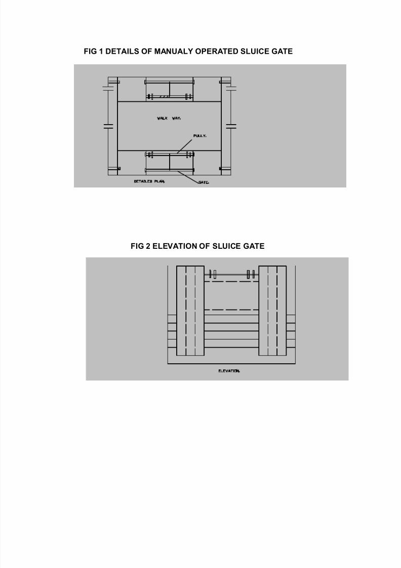
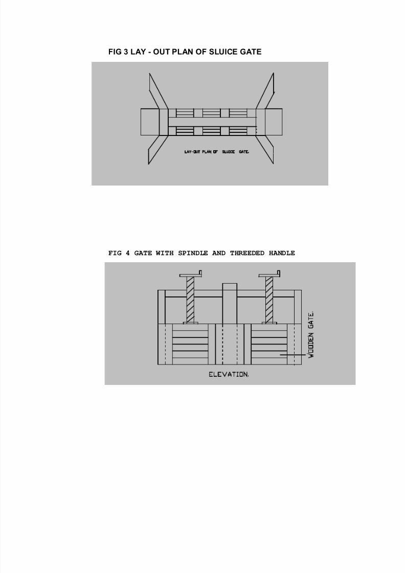
DESIGN OF SLUICE GATE
7/28/2019 solar salt
http://slidepdf.com/reader/full/solar-salt 12/27
FIG 1 DETAILS OF MANUALY OPERATED SLUICE GATE
FIG 2 ELEVATION OF SLUICE GATE
7/28/2019 solar salt
http://slidepdf.com/reader/full/solar-salt 13/27
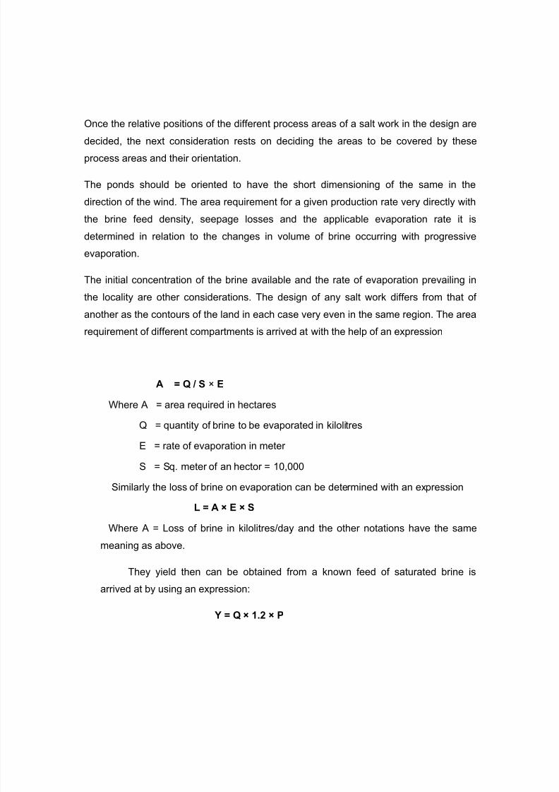
FIG 3 LAY - OUT PLAN OF SLUICE GATE
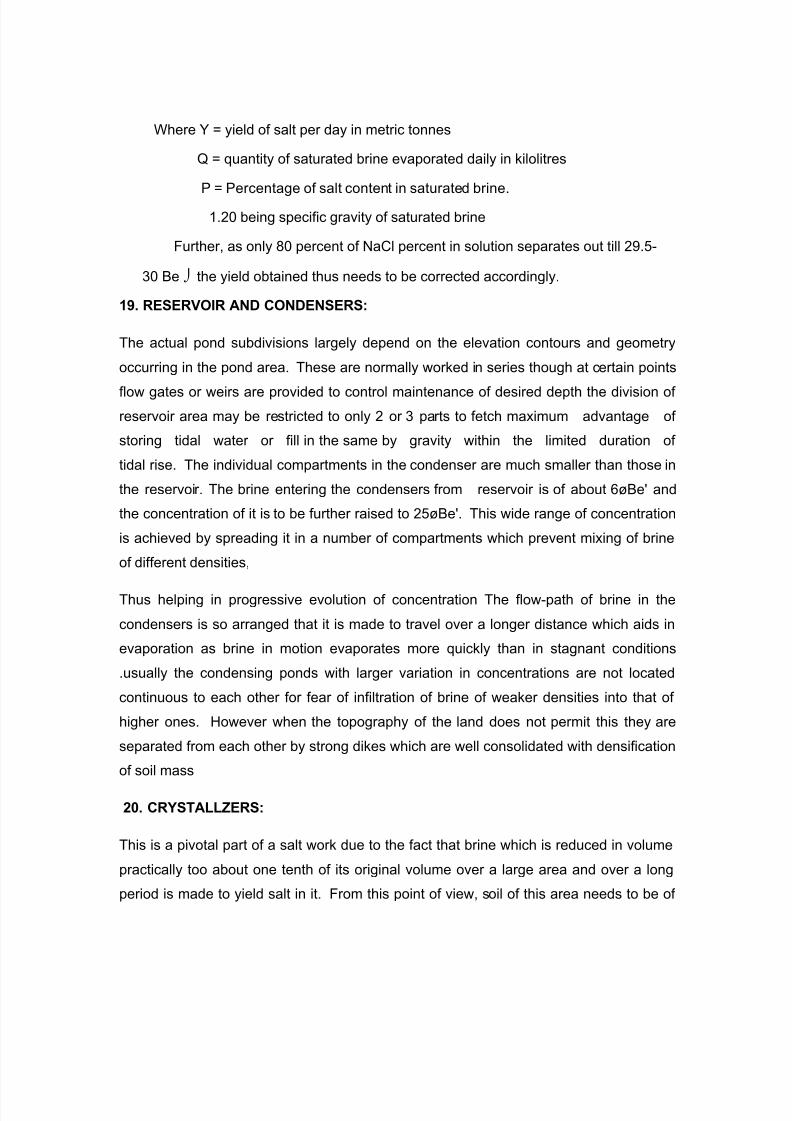
FIG 4 GATE WITH SPINDLE AND THREEDED HANDLE
7/28/2019 solar salt
http://slidepdf.com/reader/full/solar-salt 14/27
Once the relative positions of the different process areas of a salt work in the design are
decided, the next consideration rests on deciding the areas to be covered by these
process areas and their orientation.
The ponds should be oriented to have the short dimensioning of the same in the
direction of the wind. The area requirement for a given production rate very directly with
the brine feed density, seepage losses and the applicable evaporation rate it is
determined in relation to the changes in volume of brine occurring with progressive
evaporation.
The initial concentration of the brine available and the rate of evaporation prevailing in
the locality are other considerations. The design of any salt work differs from that of
another as the contours of the land in each case very even in the same region. The area
requirement of different compartments is arrived at with the help of an expression
A = Q / S × E
Where A = area required in hectares
Q = quantity of brine to be evaporated in kilolitres
E = rate of evaporation in meter
S = Sq. meter of an hector = 10,000
Similarly the loss of brine on evaporation can be determined with an expression
L = A × E × S
Where A = Loss of brine in kilolitres/day and the other notations have the same
meaning as above.
They yield then can be obtained from a known feed of saturated brine is
arrived at by using an expression:
Y = Q × 1.2 × P
7/28/2019 solar salt
http://slidepdf.com/reader/full/solar-salt 15/27
Where Y = yield of salt per day in metric tonnes
Q = quantity of saturated brine evaporated daily in kilolitres
P = Percentage of salt content in saturated brine.
1.20 being specific gravity of saturated brine
Further, as only 80 percent of NaCl percent in solution separates out till 29.5-
30 Be the yield obtained thus needs to be corrected accordingly.
19. RESERVOIR AND CONDENSERS:
The actual pond subdivisions largely depend on the elevation contours and geometry
occurring in the pond area. These are normally worked in series though at certain points
flow gates or weirs are provided to control maintenance of desired depth the division of
reservoir area may be restricted to only 2 or 3 parts to fetch maximum advantage of
storing tidal water or fill in the same by gravity within the limited duration of
tidal rise. The individual compartments in the condenser are much smaller than those in
the reservoir. The brine entering the condensers from reservoir is of about 6øBe' and
the concentration of it is to be further raised to 25øBe'. This wide range of concentration
is achieved by spreading it in a number of compartments which prevent mixing of brine
of different densities,
Thus helping in progressive evolution of concentration The flow-path of brine in the
condensers is so arranged that it is made to travel over a longer distance which aids in
evaporation as brine in motion evaporates more quickly than in stagnant conditions
.usually the condensing ponds with larger variation in concentrations are not located
continuous to each other for fear of infiltration of brine of weaker densities into that of
higher ones. However when the topography of the land does not permit this they are
separated from each other by strong dikes which are well consolidated with densification
of soil mass
20. CRYSTALLZERS:
This is a pivotal part of a salt work due to the fact that brine which is reduced in volume
practically too about one tenth of its original volume over a large area and over a long
period is made to yield salt in it. From this point of view, soil of this area needs to be of
7/28/2019 solar salt
http://slidepdf.com/reader/full/solar-salt 16/27
an almost impervious nature. The beds of crystallizers are necessarily well consolidated
and are neatly maintained. In this area sufficient good roads are provided for haulage of
salt from crystallizers to the main stacking ground. The size of an individual crystallizer
is determined with reference to the operational conditions such as use of mechanical
appliances for all or part of maintenance and harvesting operations, the method of
irrigation system followed which in turn depends on the incidence of rain during the
manufacturing period. These are constructed with due consideration to normal wind
direction. The widthwise shorter dimensional area may fall in line with the direction of
the wind to obtain benefit of increased evaporation. The optimum brine depth that is
maintained in crystallizers is between 12 to 15 cm which stands well to diurnal variations
in temperature and also to the dilution effect due to occasional incidence of rains. The
maximum numbers of crystallizers are arranged in a single row to keep the length of
roads less.
Series feeding method for quality of Common Salt
In order to improve quality and yield of common salt manufacture by solar evaporation of
brine, a system known as series feeding method which followed by western country has
been successfully tried out in our experimental salt farm, Bhavnagar. The data has
been presented which indicate the quality and quantity of salt obtained by this method
and this is compared with conventional system of manufacturing salt e.g. parallel feeding
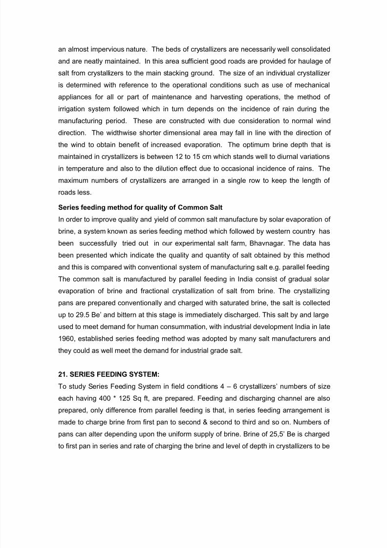
The common salt is manufactured by parallel feeding in India consist of gradual solar
evaporation of brine and fractional crystallization of salt from brine. The crystallizing
pans are prepared conventionally and charged with saturated brine, the salt is collected
up to 29.5 Be’ and bittern at this stage is immediately discharged. This salt by and large
used to meet demand for human consummation, with industrial development India in late
1960, established series feeding method was adopted by many salt manufacturers and
they could as well meet the demand for industrial grade salt.
21. SERIES FEEDING SYSTEM:
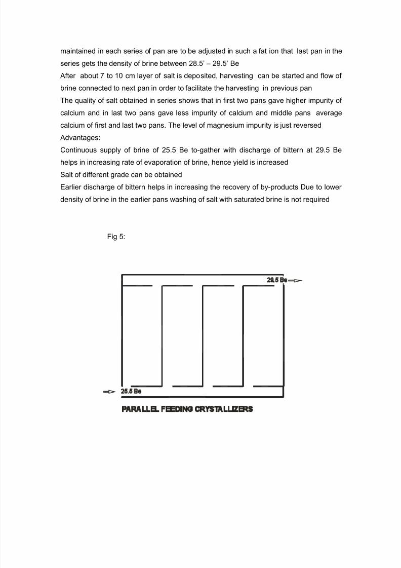
To study Series Feeding System in field conditions 4 – 6 crystallizers’ numbers of size
each having 400 * 125 Sq ft, are prepared. Feeding and discharging channel are also
prepared, only difference from parallel feeding is that, in series feeding arrangement is
made to charge brine from first pan to second & second to third and so on. Numbers of
pans can alter depending upon the uniform supply of brine. Brine of 25,5’ Be is charged
to first pan in series and rate of charging the brine and level of depth in crystallizers to be
7/28/2019 solar salt
http://slidepdf.com/reader/full/solar-salt 17/27
maintained in each series of pan are to be adjusted in such a fat ion that last pan in the
series gets the density of brine between 28.5’ – 29.5’ Be
After about 7 to 10 cm layer of salt is deposited, harvesting can be started and flow of
brine connected to next pan in order to facilitate the harvesting in previous pan
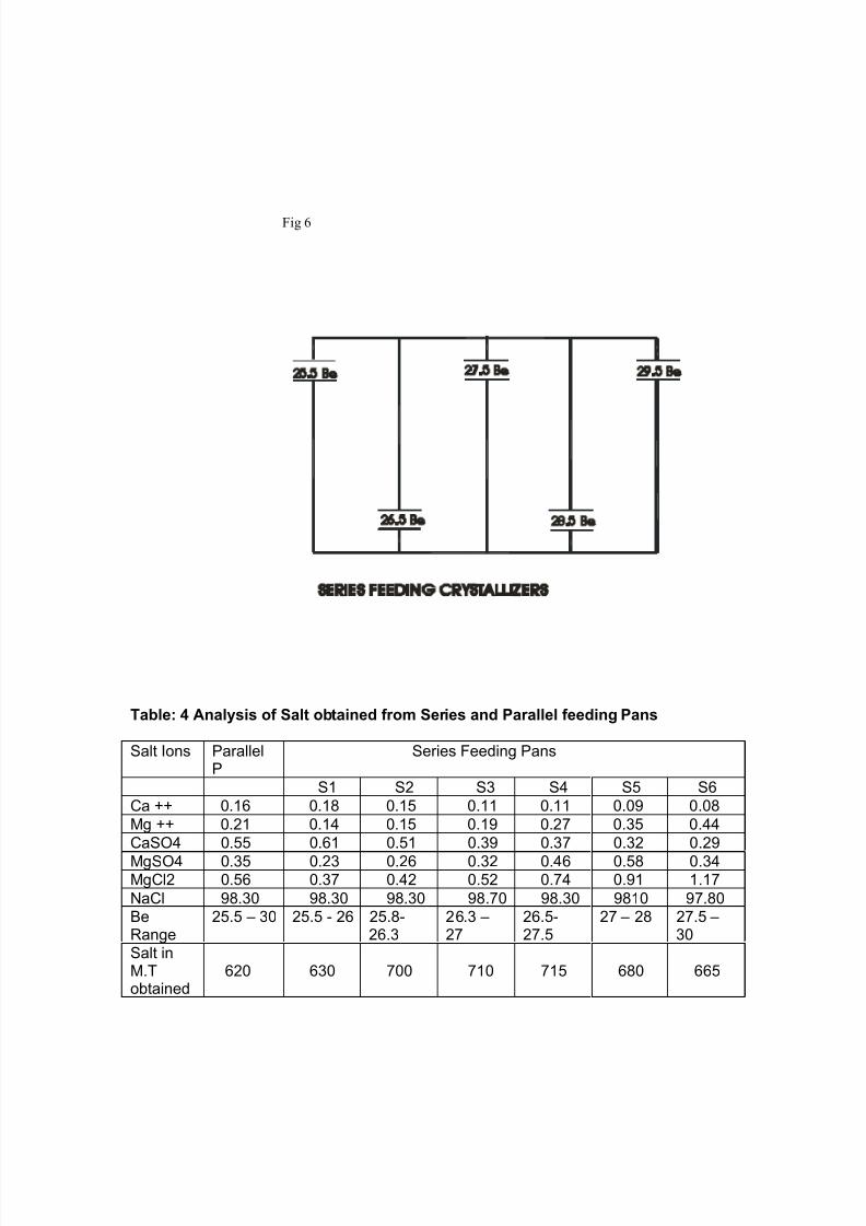
The quality of salt obtained in series shows that in first two pans gave higher impurity of
calcium and in last two pans gave less impurity of calcium and middle pans average
calcium of first and last two pans. The level of magnesium impurity is just reversed
Advantages:
Continuous supply of brine of 25.5 Be to-gather with discharge of bittern at 29.5 Be
helps in increasing rate of evaporation of brine, hence yield is increased
Salt of different grade can be obtained
Earlier discharge of bittern helps in increasing the recovery of by-products Due to lower
density of brine in the earlier pans washing of salt with saturated brine is not required
Fig 5:
7/28/2019 solar salt
http://slidepdf.com/reader/full/solar-salt 18/27
Fig 6
Table: 4 Analysis of Salt obtained from Series and Parallel feeding Pans
Salt Ions ParallelP
Series Feeding Pans
S1 S2 S3 S4 S5 S6
Ca ++ 0.16 0.18 0.15 0.11 0.11 0.09 0.08
Mg ++ 0.21 0.14 0.15 0.19 0.27 0.35 0.44
CaSO4 0.55 0.61 0.51 0.39 0.37 0.32 0.29
MgSO4 0.35 0.23 0.26 0.32 0.46 0.58 0.34MgCl2 0.56 0.37 0.42 0.52 0.74 0.91 1.17
NaCl 98.30 98.30 98.30 98.70 98.30 9810 97.80BeRange
25.5 – 30 25.5 - 26 25.8-26.3
26.3 –27
26.5-27.5
27 – 28 27.5 –30
Salt inM.Tobtained
620 630 700 710 715 680 665
7/28/2019 solar salt
http://slidepdf.com/reader/full/solar-salt 19/27
22. CHANNELS AND ROADS:
Channels are provided to flow the brine in concentrating ponds to negotiate areas which
are not accessible with straight gravity flow. Such channels are wide as large quantities
of brine move through them. These channels may be longer which afford more
circulating area and thus aid evaporation. Channels in crystallizer area meant to feed
crystallizers with saturated brine are meant to carry the mother liquor discharged from
them. The feeding channel because of the increased value of the concentrated brine
needs to be shorter. Their width at the base is not more than 50 cm. They are required
to be constructed just above the bed level of the crystallizers with a gentle gradient of 1
Cu M a length of every 35 meters. The bittern channels need to be located with their
base level 15 cm below the bed level of crystallizers and have 1.5
Times steep gradient then the feeding channels. The feeding and bittern channels are
located away from each other to avoid bitterns finding way in the crystallizers. Roads in
a salt work are of necessity constructed on the embankments. Such roads mainly serve
three purposes viz. (I) to facilitate transport of salt, (ii) to provide access to the chief
points of operation and (iii) to provide access to different areas for maintenance work.
The roads No.1 are more important and are constructed as permanent feature.
Transportation planning should be integrated with all management planning to obtain
more economy through increased sufficient turnover.
23. EMBARKMENTS:
There are two types of embankments viz., (I) outer protective embankments and (ii)
inner partition embankments. The dimensions of the various embankments in salt works
differ according to their location and water level rising against it. The outer
embankments are required to have an approximately one meter free board above the
highest tidal rise in the area. These embankments may have a top width of 4 meters to
permit vehicular traffic. The movements of vehicular traffic on it impart an advantage of
7/28/2019 solar salt
http://slidepdf.com/reader/full/solar-salt 20/27
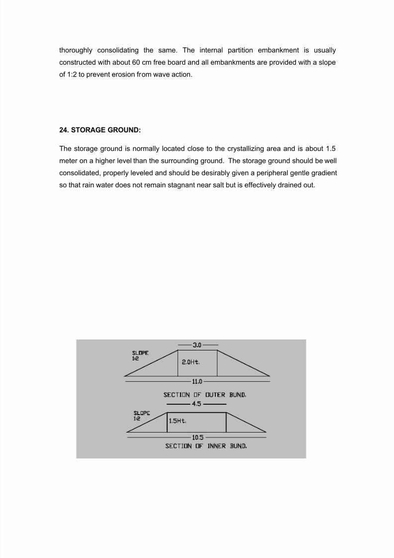
thoroughly consolidating the same. The internal partition embankment is usually
constructed with about 60 cm free board and all embankments are provided with a slope
of 1:2 to prevent erosion from wave action.
24. STORAGE GROUND:
The storage ground is normally located close to the crystallizing area and is about 1.5
meter on a higher level than the surrounding ground. The storage ground should be well
consolidated, properly leveled and should be desirably given a peripheral gentle gradient
so that rain water does not remain stagnant near salt but is effectively drained out.
7/28/2019 solar salt
http://slidepdf.com/reader/full/solar-salt 21/27
Fig 7: Section of the outer and inner bunds
25. EQUIPMENTS:
In large solar ponds, pumps are used for pumping in sea water or for pumping brine at
some stage or the other due to gradient variations. These are also used for discharging
out bitterns from the crystallizer area; numerous types of pumps are used in different salt
works. The type of pump and the material of its construction depend on the liquid to be
handled and the lift required. Generally the requirement of salt works in low head andhigh capacity and the liquid to be handled is denser than water. For this vertical,
centrifugal mixed flow and axial flow pumps are commonly found suitable. Directly
coupled pumps are more efficient due to less friction loss. The material of construction
for pumps used for pumping sea brine of specific gravity 1.03 may be usual cast iron
impeller, and 2 percent nickel cast iron causing suction flare for those used for pumping
brine of higher concentrations the impeller of bronze and stainless steel shaft are
recommended. These pumps meet with special problems like high corrosive action or
brine and bitterns and precipitation of gypsum and salt. For this reason it is necessary toprovide a hand hold to facilitate cleaning the same.
26. PUMPING:
Pumping is mostly done with centrifugal pumps. These pumps are generally low head,
high capacity type. Material of this pump is generally of cast iron. Impellers are also
made of Cast Iron. Bronze impeller with cast iron body is not recommended because of
galvanic action between the two dissimilar metals which increases corrosion of
impellers. Worthhite impellers and rings have no such drawbacks. This type of impeller and the rings have service record of 10 – 15 years. Worthhite is complex alloys
containing 46 – 47 % Fe, 20 % Cr, 24 % Ni, 3 % Mo, 3.25 % Si, Cu, Mn, and 0.70 % C.
The impellers are made of Ni – Resist and Monel metals. Nickel is suitable for hot brine
circulation pumps.
7/28/2019 solar salt
http://slidepdf.com/reader/full/solar-salt 22/27
Ejecto type pumps can be used where suction lift is more then 7 meters. Use of
submersible pumps for under ground brine pumping is mostly used. The pumps used in
salt works are driven by electric motor or by diesel or petrol engines
27. PUMP SPECIFICATION:
Vertical axil flow pumps single stage having discharge feature with elbow construction
are normally used for brine pumping depending upon capacity requirement. They are
highly efficient and large volume of water are Pumped. These pumps are ideal for
permanent installation having good sump design. Proper sump design is of almost
importance since uniform movement of water is essential for good performance of
pumps. Sumps should be so design and constructed for affecting a short and straight
flow of water to the pump with flow speed of not more then 2 ft per second, more over
pump should be mostly of square or even rectangular construction without any attempts
being made to bevel the corners. For optimum performance the distance from the
suction bell diameter the distance from centre line of the pump to the side was equal to
one suction Bell diameter and the distance from centre line of the pumps on the back
well be two third of the suction bell diameter. If two or more pumps are installed at the
same station each should have its own separate compartments
Sea water pumps are mainly of Mild Steel material of construction and can also be
manufactured in Cast iron as a material of construction to the specification requirement
of the customer
7/28/2019 solar salt
http://slidepdf.com/reader/full/solar-salt 23/27
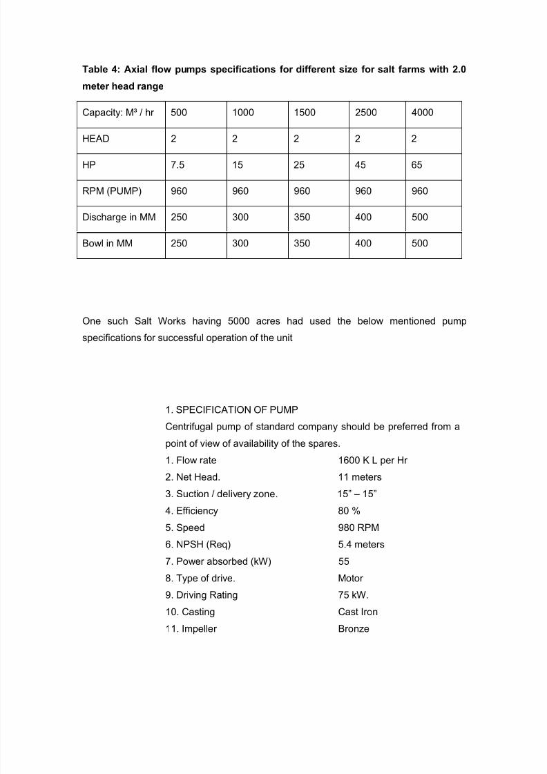
Table 4: Axial flow pumps specifications for different size for salt farms with 2.0
meter head range
Capacity: M³ / hr 500 1000 1500 2500 4000
HEAD 2 2 2 2 2
HP 7.5 15 25 45 65
RPM (PUMP) 960 960 960 960 960
Discharge in MM 250 300 350 400 500
Bowl in MM 250 300 350 400 500
One such Salt Works having 5000 acres had used the below mentioned pump
specifications for successful operation of the unit
1. SPECIFICATION OF PUMP
Centrifugal pump of standard company should be preferred from a
point of view of availability of the spares.
1. Flow rate 1600 K L per Hr
2. Net Head. 11 meters
3. Suction / delivery zone. 15” – 15”
4. Efficiency 80 %
5. Speed 980 RPM
6. NPSH (Req) 5.4 meters
7. Power absorbed (kW) 55
8. Type of drive. Motor
9. Driving Rating 75 kW.
10. Casting Cast Iron
11. Impeller Bronze
7/28/2019 solar salt
http://slidepdf.com/reader/full/solar-salt 24/27
12. Shaft. 316 SS
13. Sealing arrangement. Clad packing.
14. H.P 100
28. VEHICLES FOR TRANSPORT OF SALT:
Usually a well laid traction line may be provided centrally in the crystallizers with
bifurcations to serve all the crystallizers on either side. But where initial expenditure is
considered prohibitive, a substitute transport facility can be provided by tractor and trailer
29. BELT CONVEYORS:
It is desirable to have sufficient number of stackers to meet with all the requirement of
storage of salt during the harvesting season. They need to be light in weight so that their
movement from place to place is facilitated. They are however required to be sufficiently
strong. Normally M.S. tubular frame satisfies both the requirements.
30. CONVEYOR FOR SALT:
Galvanized radial stacker for salt application is now available which is resistance to
corrosion for considerable time The conveyor 90 CMS belt Width driven by 150 hp
electric motor where function is to elevate the salt to sufficient height to permit feeding
into the ship at the point of jetty.
31. BELT CONVEYOR SPECIFICATION:
Belt conveyors should mean for Atomization of Industrial product to convey the required
material from one place to another by means of various systems to feed, store, process
depending on the application.
32. SCREW CONVEYOR: A Screw Conveyor is also known as flexion flexible screw
conveyor, a special conveyor, a spiral conveyor, screw conveyor, helix conveyor or
center less auger conveyor. How ever simple design reduce maintenance cost and
some of the feature of screw conveyor is given below
7/28/2019 solar salt
http://slidepdf.com/reader/full/solar-salt 25/27
Diameter Range: 75MM to 1000 MM
Pitch Range: 75MM pitch to 600MM pitch
Thickness: up to 12MM
Application Area: In Inclined / Straight / Vertical lifts, feeders and flexible type
Use: To convey sand crescent or any material in powder, granular or cake form in mild
steel and stainless steel.
Depending on needs, ONE CAN use rubber, PVC, Oil grade, Polyethylene, nylon
sandioitc etc. The structure of the conveyor is made in mild steel or stainless steel. The
conveyor solutions vary from light duty to heavy duty conveying.
Application Areas: In the Food Industry, Package Handling, Sand & Gravel, Cement,
coal, packs, etc.
Pipe Thread Conveyor: It is a hydraulic operated conveyor that is used for threading of
pipe, from 4 ½" diameters to 13 3/8" diameter and of 13 meter length. These pipe thread
conveyors are used for off shore plane oil exploration with the following types of rollers:
"V" roller for to and fro motion driven by hydrometers
Guide rollers for turn motion for threading on oil country laths
Turn table "V" roller having rubber coating complete with power pack 10
Hp. Motor
(1) Reddle Conveyor: They are available in both forms, straight as well as
bend and convey the material up to 90%. They have the ability to handle a bulk
mass of up to 200 T.P.O. (2)
Roller Conveyor: Roller conveyors are used in industries in which a continuous
process is carried on. Hence, it finds its applications in packing industries,
pharmaceutical industries, steel foundries for mould filling etc. Some of the
features of roller conveyors are:
(A) They are used to convey the “poured mould” of any desired length, to stake
out table.
(B) They are available in mild steel construction, stainless construction or
aluminum construction.
7/28/2019 solar salt
http://slidepdf.com/reader/full/solar-salt 26/27
(C) They can be manually operated and motor driven.
(D) Bucket Elevator: A bucket elevator, also called a grain leg, is a mechanism
for hauling flow able bulk materials like salt, grain or fertilizers.
(E) They convey the material in vertical or inclined position.
(F) They are used to convey the “poured mould” of any desired length, to stake
out table.
(K) They can be manually operated and motor driven.
(L) They are available in mild steel construction, stainless construction or
aluminum construction.
(M)Have the capacity to handle materials from 1 tonne to 200 T.P d.
(N) The buckets available can be in-pressed buckets, fabricated buckets or PVC
buckets; as per your requirements.
(O) They can be built to the desired height and are duly mounted on chains in
mild steel, alloy steel or simply belt mounted.
(P) Slate Conveyor: These overhead conveyors are used to convey bags or for
packing. We manufacture and export slate conveyors in:
(Q) Three wheel or towhead pillar type drive or
(R) Wheel construction with cater pillar type drive
33. ROLLERS:
Cast iron drum rollers of 1.2 m diameter and 1.8 m width having an initial dead weight of
about 1200 to 1400 Kegs is suitable for rolling operations of crystallizers. This can be
provided with an arrangement to fill in with water so as to increase its weight to 3 tonnes.
Such a roller is found useful in consolidating the embankments, roads and like wise also.
Road roller is a vehicle often equipped with heavy wide smooth rollers for compacting
roads and pavements & Soil of different textures
The systems adopted easily operated mechanical steering comprising of worm shaft and
gear. They are designed to give jerk free movement to the front rolls. The adjustable and
reversible scrapers are fitted to cover the entire width of all rolls. The rolls are fabricated
out of mild steel plate and electrically welded and tested.
7/28/2019 solar salt
http://slidepdf.com/reader/full/solar-salt 27/27
The brakes provided with fully self-wrapping and external contracting type, fitted with
replaceable brake lining and adjustable. They often controlled by a foot-pedal or hand-
wheel independently. The sprinklers and the water tank provided with a fixed pump that
feed water into the water tank. They are provided with a heavy clutch and gearbox.
Some clutches work double types and often controlled by a single hand lever. They are
often provided with differential locking arrangement, which is operated from the driver's
seat.
34. VIBRATING ROLLER:
This roller has articulated frame,
the vibrating roller keeps on the ground and vibrates horizontally getting the required
compact thickness more quickly; It can protect and press those subject to vibration.Scraper and sprinkling devices on drums and Compacting force up to 13 tonnes
Roller is used for compaction of hot asphalt, soil, course aggregate and Mix materials in
Road making and for sports ground. Main feature is the driving power that would be
provided by an engine mounted on front frame. Moving transmission and vibration drives
with reliable performance. Frame and drum hydrostatic drive. The vibratory roller keeps
on the ground and vibrates horizontally, getting the required compacted thickness more
quickly. Automatic disengage system is activated when the traveling direction changed.
Roller should have double amplitude and frequencies in order to allow optimum
compaction. Scraper and sprinkling devices on Drum. Hydrostatic articulated center joint
for good mobility for hydraulic steering system.