Embed Size (px)
Citation preview
Solar Sail
Department of Aerospace Engineering and Mechanics
AEM 4332W – Spacecraft Design
Spring 2007

2
Team Members
3
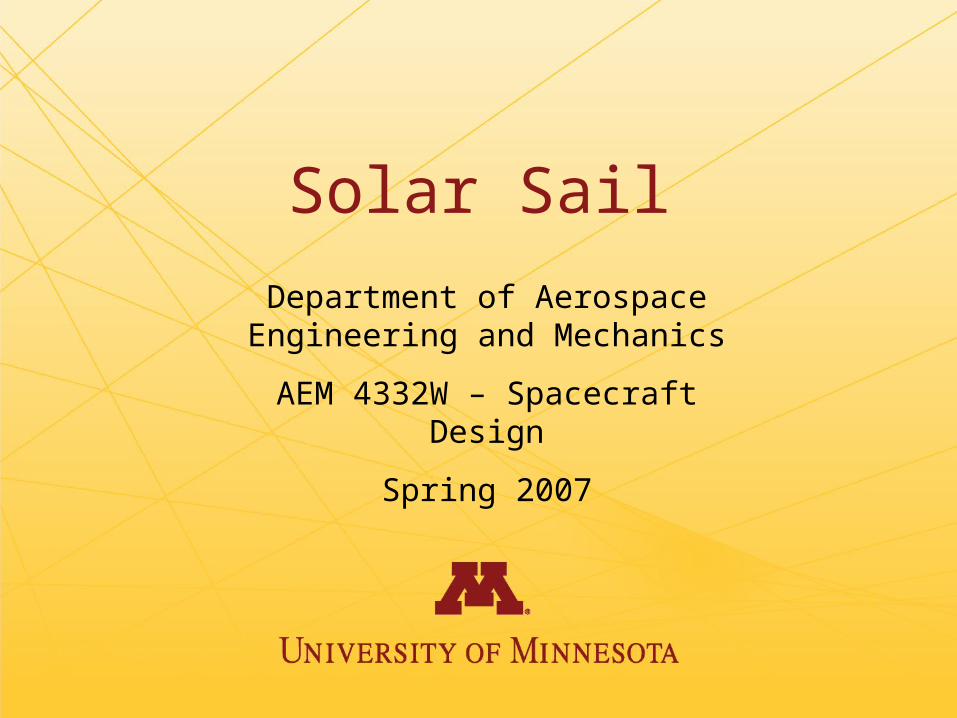
Solar Sailing:

4
Project Overview

5
Design Strategy

6
Trade Study Results
Orbit
Eric Blake
Daniel Kaseforth
Lucas Veverka

Eric Blake
Optimal Trajectory of a Solar Sail: Derivation of Feedback Control Laws

9
Recall Orbital Mechanics
• The state of a spacecraft can be described by a vector of 6 orbital elements.– Semi-major axis, a– Eccentricity, e– Inclination, i– Right ascension of the ascending node, Ω– Argument of perihelion, ω– True anomaly, f
• Equivalent to 6 Cartesian position and velocity components.

10
Orbital Elements

11
Equations of Motion
vr
nnrr
rr
v2^
2
^
2
^^^^
sinsincossincos rpprn
^
r
^
p
^^
rp
n
linesun
sail
= Sail Lightness Number = Gravitational Parameter

12
Problem: Minimize Transfer Time
1),,(2^
2
^
2
nnr
rr
rvuxH vvr
^
r
^
p
^^
rp
n
linesun
sail
^^^
353)(2))((2)(3 rnrnnnr
rrr
rr vrvr rv
^^
}max{ vv nn
By Inspection:
Transversality:
fttv
ttv npnr
rnpnr
r
2
^
22
^
2)()(
0
13
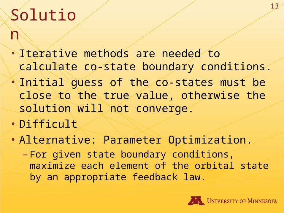
Solution
• Iterative methods are needed to calculate co-state boundary conditions.
• Initial guess of the co-states must be close to the true value, otherwise the solution will not converge.
• Difficult• Alternative: Parameter Optimization.
– For given state boundary conditions, maximize each element of the orbital state by an appropriate feedback law.

14
Orbital Equations of Motion
r
pTfSe
e
pr
df
dasin
)1(
222
2
e
p
rTf
p
rTfS
r
df
decos1sin
2
Wfp
r
df
di)cos(
3
Wfip
r
df
d)sin(
sin
3
f
p
rTfS
e
ri
df
d
df
dsin1coscos
2
12
2sin1cos1
f
p
rTfS
e
r
r
p
dt
df
)1( 2eap fe
pr
cos1
32
cosr
S sinsincos22r
T cossincos22r
W
),,( xgx
= Sail Lightness Number = Gravitational Parameter
15
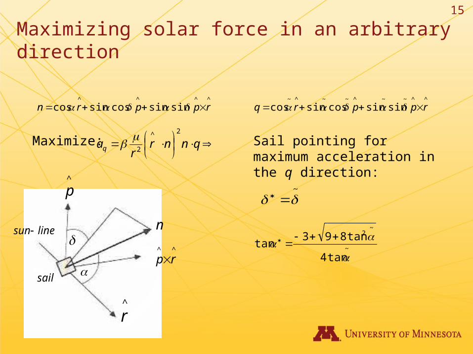
Maximizing solar force in an arbitrary direction
^^^^
sinsincossincos rpprn ^^~~^~~^~
sinsincossincos rpprq
^
r
^
p
^^
rp
n
linesun
sail
Maximize:
qnnr
raq
2^
2
~
~
~2
tan4
tan893tan
Sail pointing for maximum acceleration in the q direction:

16
Locally Optimal Trajectories• Example: Use parameter optimization method to derive
feedback controller for semi-major axis reduction.
• Equations of motion for a:
r
pTfSe
e
pr
df
dasin
)1(
222
2
3
2cos
rS
sinsincos22r
T
fe
fe
cos1
sintan
~
fe
pr
cos1 )1( 2eap
2
~
~2
tan4
tan893tan
Feedback Law:
Use this procedure for all orbital elements
17
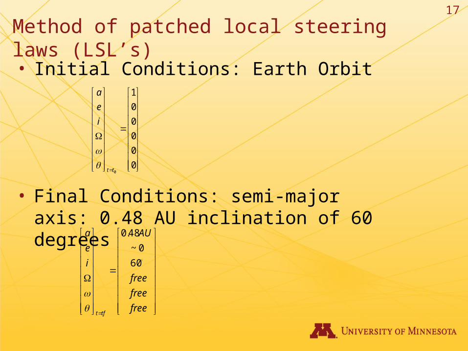
Method of patched local steering laws (LSL’s)
• Initial Conditions: Earth Orbit
• Final Conditions: semi-major axis: 0.48 AU inclination of 60 degrees
0
0
0
0
0
1
0tt
i
e
a
free
free
free
AU
i
e
a
tft
60
0~
48.0
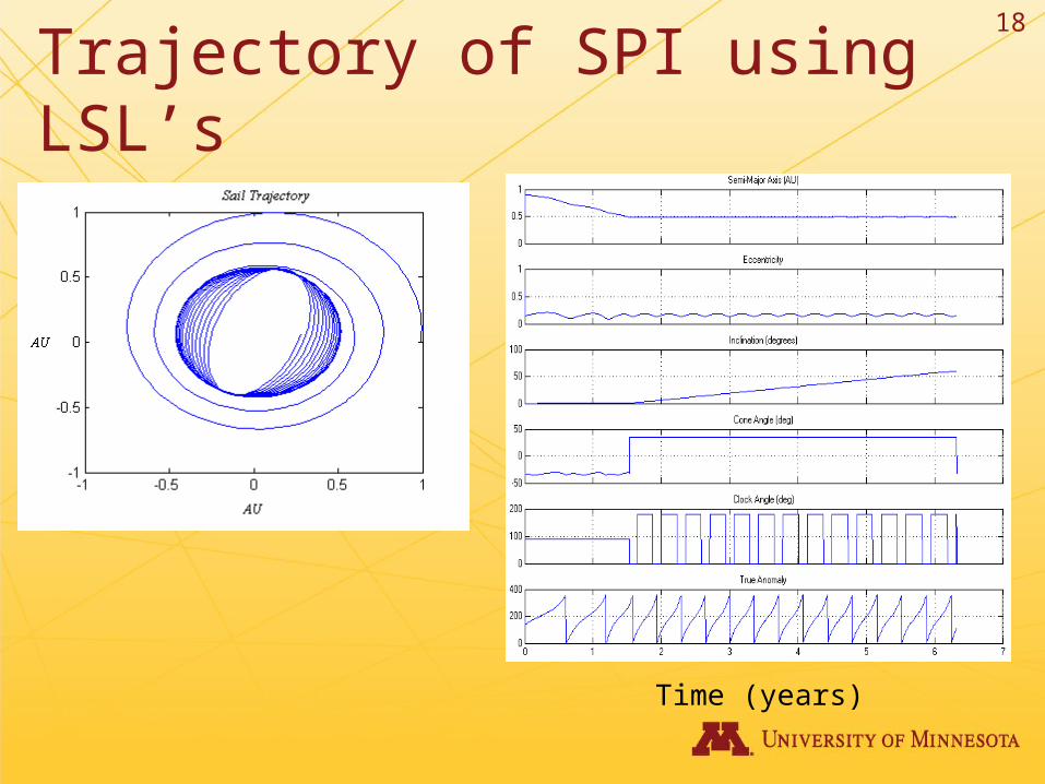
18
Trajectory of SPI using LSL’s
Time (years)

19

20
Global Optimal Solution– Although the method of patched LSL’s is not ideal, it is a solution that is
close to the optimal solution.
– Example: SPI Comparison of LSL’s and Optimal control.
21
Conclusion
• Continuous thrust problems are common in spacecraft trajectory planning.
• True global optimal solutions are difficult to calculate.
• Local steering laws can be used effectively to provide a transfer time near that of the global solution.

Lucas Veverka
•Temperature
•Orbit Implementation

23

Daniel Kaseforth
Control Law Inputs and Navigation System

25

Structure
Jon T Braam
Kory Jenkins

Jon T. BraamStructures Group:
• Primary Structural Materials
• Design Layout
•3-D Model
• Graphics

28
Primary Structural Material
Weight and Volume Constraints• Delta II : 7400 Series • Launch into GEO
– 3.0 m Ferring» Maximum payload mass: 1073 kg» Maximum payload volume: 22.65 m3
– 2.9 m Ferring» Maximum payload mass: 1110 kg» Maximum payload volume: 16.14 m3
29
Primary Structural Material
Aluminum Alloy Unistrut– 7075 T6 Aluminum
Alloy• Density
– 2700 kg/m3
– 168.55 lb/ft^3
• Melting Point– ? Kelvin
Picture of Unistrut

30
Primary Structural Material
• Density
• Mechanical Properties– Allowing unistrut design
• Decreased volume
• Thermal Properties– Capible of taking thermal loads

31
Design Layout
• Constraints– Volume– Service task– Thermal consideration– Magnetic consideration– Vibration– G loading

32
Design Layout
• Unistrut Design– Allowing all inside surfaces to be bonded to
• Titanium hardware
– Organization• Allowing all the pointing requirements to be met with
minimal attitude adjustment

33
Design Layout
• Large Picture of expanded module

34
3-D Model
• Large picture

35
3-D Model
• Blah blah blah (make something up)

36
Graphics
• Kick ass picture

37
Graphics
• Kick ass picture
38
• The blanks will be filled in soon

39
Trade Studies
• Blah blah blah

40
Why I deserve an “A”
• Not really any reason but when has that stopped anyone!
Kory Jenkins• Sail Support Structure• Anticipated Loading•Stress Analysis• Materials•Sail Deployment

42

Attitude Determination and Control
Brian Miller
Alex Ordway

Alex Ordway
•Sliding Mass vs. Tip Thrusters
•Component Selection

45

Brian Miller
•Tip Thrusters vs. Slidnig Mass
•Attitude Control Simulation

47
Attitude Control
• Conducted trade between tip thrusters and sliding mass as primary ACS
• Considerations– Power required– Torque produced– Weight– Misc. Factors

48
Attitude Control
• Tip Thrusters (spt-50)– Pros
• High Torque Produced ~ 1.83 N-m• Low weight ~ 0.8 kg/thruster
– Cons• Large Power Requirement ~ 310 Watts• Lifetime of 2000 hrs• Requires a fuel, either a solid or gas

49
Attitude Control
• Attitude Control System Characteristics– Rotational Rate– Transfer Time– Required Torque– Accuracy– Disturbance compensation

50
Attitude Control
• Requirements– Orbit
• Make rotation rate as fast as possible
• Roll spacecraft as inclination changes
– Communications– Within Maximum Torque
• Pitch and Yaw Axis
~ 0.34 N-m
• Roll Axis
~ 0.2 N-m
M
mFzU
m – sliding massF – solar forcez – distance from cgM – spacecraft mass

51
Attitude Control
• Pitch and Yaw Axis • Rotation Rate = 0.144 rad/hr
~ 8.25 deg.
• Transfer Time = 5300s ~ 1.47 hrs
• Required Torque = 0.32 N-m
~ 98.8% of maximum produced
• Converges to desired angle
Slope = 0.00004 rad/s
Torque Req.
Transfer Time

52
Attitude Control
• Roll Axis • Rotation Rate = 0.072 rad/hr
~ 4.12 deg
• Transfer Time = 7000s ~ 1.94 hrs
• Required Torque = 0.15 N-m
~ 75% of maximum produced
• Converges to desired angle
Torque Req.
Slope = 0.00002 rad/s
Transfer Time

53

Power, Thermal and Communications
Raymond Haremza
Michael HitiCasey Shockman

Raymond HaremzaThermal Analysis
•Solar Intensity and Thermal Environment•Film material•Thermal Properties of Spacecraft Parts•Analysis of Payload Module•Future Work

56

Casey ShockmanCommunications

58

Michael HitiPower

60

61
Demonstration of Success

62
Future Work

63
Acknowledgements
• Stephanie Thomas
• Professor Joseph Mueller
• Professor Jeff Hammer
• Dr. Williams Garrard
• Kit Ru….
• ?? Who else??


![ESAIL D61.1 E-sail mission document - Electric sail · 2013-12-02 · The American mission NEAR Shoemaker was the first spacecraft to land on an asteroid [13]. The Japanese Hayabusa](https://img.pdfslide.us/doc/110x75/5edaf79709ac2c67fa6898c3/esail-d611-e-sail-mission-document-electric-sail-2013-12-02-the-american-mission.jpg)